Article

Numerical Characterization of Cohesive and Non-Cohesive ‘Sediments’ under Different Consolidation States Using 3D DEM Triaxial Experiments

1
Dr. Moses Strauss Department of Marine Geosciences, Leon Charney School of Marine Sciences (CSMS), University of Haifa, Haifa 3498838, Israel
2
MARUM–Centre for Marine Environmental Sciences, University of Bremen, Leobener Str. 8, 28359 Bremen, Germany
3
Institute for Geotechnical Engineering, Leibniz University of Hannover, Welfengarten 1a, 30167 Hannover, Germany
4
U.S. Geological Survey, Woods Hole Coastal and Marine Science Centre, Woods Hole, MA 02543, USA
*
Authors to whom correspondence should be addressed.
Processes 2020, 8(10), 1252; https://doi.org/10.3390/pr8101252
Submission received: 9 September 2020 / Revised: 1 October 2020 / Accepted: 1 October 2020 / Published: 5 October 2020
(This article belongs to the Special Issue DEM Simulations and Modelling of Granular Materials)

Abstract

:
The Discrete Element Method has been widely used to simulate geo-materials due to time and scale limitations met in the field and laboratories. While cohesionless geo-materials were the focus of many previous studies, the deformation of cohesive geo-materials in 3D remained poorly characterized. Here, we aimed to generate a range of numerical ‘sediments’, assess their mechanical response to stress and compare their response with laboratory tests, focusing on differences between the micro- and macro-material properties. We simulated two endmembers—clay (cohesive) and sand (cohesionless). The materials were tested in a 3D triaxial numerical setup, under different simulated burial stresses and consolidation states. Variations in particle contact or individual bond strengths generate first order influence on the stress–strain response, i.e., a different deformation style of the numerical sand or clay. Increased burial depth generates a second order influence, elevating peak shear strength. Loose and dense consolidation states generate a third order influence of the endmember level. The results replicate a range of sediment compositions, empirical behaviors and conditions. We propose a procedure to characterize sediments numerically. The numerical ‘sediments’ can be applied to simulate processes in sediments exhibiting variations in strength due to post-seismic consolidation, bioturbation or variations in sedimentation rates.

1. Introduction

Many new and comprehensive datasets characterize the sediment-physical behavior of subaerial and submarine sediments based on laboratory experiments (e.g., [1,2,3,4]) and in-situ measurements monitoring stress conditions and deformation processes (e.g., [5]). However, despite new technological developments, our knowledge of sediment behavior cannot always sufficiently explain the deformational processes. This gap in the knowledge arises from the fact that many deformational processes cannot be directly observed, being too fast or too slow to be directly monitored (e.g., gravitational mass movements) or because they occur below the Earth’s surface (e.g., failure plane and fault mechanics at different depth levels). Under these circumstances, numerical process simulations have been applied to develop conceptual models for such processes (e.g., [6,7]).
In addition to classical continuum models, numerical granular techniques, such as the Discrete Element Method (DEM [8]), have been used to investigate the full range of deformational processes—for example, simulating the large-scale long-term evolution of fold-and-thrust belts [9], short-term mass-movements kinematics [10] or small-scale geo-processes on various time scales [7,11].
The DEM is based on a granular approach where the model domain contains an assembly of individual, discrete particles. Interactions between these particles are subjected to contact models and individual particle properties (micro-properties; see Section 2) [12]. Depending on the applied particle contact model and the particle properties, different material behaviors can be simulated. This includes elastoplastic deformation following the Mohr–Coulomb brittle criteria [6] to a viscous deformation [13].
A particularity of numerical granular media is that the macro-properties of a particle assembly differ from the defined micro-properties of individual particles [14]. For example, the particle’s friction coefficient micro-property influences the particle rolling behavior and therefore the shear strength of the bulk material [15]. Another important property is the influence of particle shape and roughness (e.g., [7,16,17,18,19,20]). Using elliptical and ellipsoidal shaped particles, Thornton [18] proposed that particle shape effects the deformation behavior of the material, whereas Guo and Morgan [19] showed that an angular particle shape results in a higher frictional strength. Focusing on the micro-fabric break down, Kock and Huhn [7] demonstrated subsequent shear zone localization. Though elliptically shaped particles capture the deformation behavior of granular materials such as sands very well, most researchers use disc and spherical particles since the calculation algorithms of elliptical particles significantly increase computation time [10,11,14,19,21,22,23,24,25].
The current study aims to test specific DEM micro-particle properties to generate a set of different sediment types and their deformation behavior in 3D. Our simulations focused on mimicking sand and clay mechanical behavior with a wide range of cohesion and strength values. Sand and clay were chosen as the two compositions are endmembers of siliciclastic sediments. The shear strength of these endmembers was chosen as the main focus, because it strongly influences the rate and style of deformation [1,13,26,27,28].
We applied the bonded numerical approach to simulate clay cohesive strength between particles (i.e., bonded materials), which is not present in cohesionless material (i.e., granular materials) [14]. Several studies used this approach in 2D but mainly focused on simulating brittle deformation in rocks (e.g., [6,29]). To the best of our knowledge, granular (cohesionless) vs. bonded materials (cohesive) have not yet been comprehensively tested in 3D and their applicability for the simulation of sand and clay sediments has not been investigated. Additionally, we tested the role of the consolidation state, which can be indicated by loose and dense particle packing for both granular and bonded materials. These endmember properties simulate a range of ‘sands’ and ‘clays’. Finally, we tested three different stress states to simulate different burial depths of the ‘sediments’ to achieve different responses to loading.
We adopted the approach and procedures used in geotechnical and numerical tests to build numerical 3D triaxial tests (e.g., [3,30]). Analyses of these numerical triaxial tests enabled the collection of detailed information regarding different particle packing states: (i) their stress–strain curve or deformation behaviors, and (ii) the resulting macro-properties, e.g., cohesion.

2. The Discrete Element Method—Granular and Bonded Approach

The Discrete Element Method is a numerical technique to simulate the interactions between solid granular particles via discrete contact points. Within a model domain, each particle is defined by a set of micro-properties such as density ( ρ p ); in the following index, ‘p’ indicates micro-properties defined for individual particles) and coefficient of friction ( μ p ). These micro-properties are included in the force calculation at each contact point using pre-defined contact models [8]. Contact models (also termed contact laws) control the overall physical behavior of particle assemblages and define the interaction between particles. The force–displacement calculations are described in detail in Appendix A.
We used the commercial software Particle Flow Code 3D (PFC3D) by ITASCATM to investigate the mechanical behavior of numerical ’sediments’. The software implements the DEM technique following principles defined by Cundall and Strack [12] and offers several contact models to generate different mechanical behaviors [31]. We selected the Hertz–Mindlin contact model to generate a cohesionless granular material (sand-like; see Section 2.1) and the linear parallel-bond contact model to generate a cohesive, elastoplastic behavior (clay-like, see Section 2.2). Both contact models were previously applied using PFC and other discrete element software to generate a range of geo-materials such as soils and rocks [17,29,32,33].
It is important to note that, although in each model parameters are assigned per particle as micro-properties, we do not assume that a single particle represents a single sediment grain. The overall assembly of particles represents an averaged macro-mechanical behavior of a bulk sediment sample. To make DEM applicable and achieve insights into the mechanical deformation behavior of a natural material, some micro-properties need to be adjusted so that the particle assemblage behaves macroscopically as an elastoplastic material. Therefore, it does not reproduce the whole range of sediment behavior (e.g., neglecting clay electro-chemical forces) but rather a first-order approximation of stress–strain behavior (e.g., [34,35]).

2.1. Granular Approach: The Hertz–Mindlin Contact Model (Cohesionless, Elastoplastic)

The contact between two spherical elements is a spherical 3D contact that becomes a circular area once load is applied [36]. The Hertz theory accounts for such a non-linear interaction contact behavior between smooth and elastic spheres. To account for the frictional behavior, the Mindlin model describes the tangential forces that develop at the contact between two spherical elements [37]. The combined Hertz–Mindlin contact model applies the Hertz approach as an elastic response in the normal direction, and the Mindlin approach in the tangential direction along with Coulomb’s friction model [37]. The Hertz–Mindlin contact model has been previously used to simulate sands, soils and fault gouge material [14,38,39] and is applied here as well to simulate sand mechanical behavior.
In PFC3D, the input parameters for the Hertz–Mindlin contact model are the elastic constants of the particles, namely the micro-shear modulus ( G p ) and the micro-Poisson’s ratio ( ν p ). These two are the required elastic constants to calculate the forces in the normal and tangential directions ( F n and F s , accordingly). The shear modulus is the elastic stiffness of a material and defines the material resistance to shearing deformation. Under small strains, the shear modulus of a bulk material depends on the confining pressure stress and the packing condition (i.e., porosity) of the particles and therefore it is an indicator of the material’s structure and strength [40]. A fixed micro- coefficient of friction ( μ p ) and density ( ρ p ) values are also assigned to each particle. The micro-shear modulus and micro-Poisson’s ratio are implemented in the normal and tangential stiffness ( k n and k s , accordingly) calculations (Figure 1a) according to the following Equations:
k n = ( 2 G p · 2 R ¯ 3 ( 1 ν p ) ) ,
k s = ( 2 ( 3 G p 2 ( 1 ν p R ¯ ) ) 1 / 3 2 ν p ) · F n 1 3 ,
where R ¯ is the average radius of the two particles that are in contact [31].

2.2. Granular Cohesive Approach: The Linear Parallel-Bond Contact Model (Cohesive, Elastoplastic)

Cohesive strength in clay-like sediments originates from the electrostatic attraction between clay particles and is a stress-independent component of the shear strength [41]. In DEM, however, the bonds implemented between the particles are used to simulate the interaction, the resulting forces and the strength that the bond can sustain. The linear parallel-bond contact model was created to simulate a cemented granular material [42]. The model introduces a rigid inter-particle bonding, thus generating cementation or cohesive strength [33,42]. Such an approach provides the mechanical behavior of a glue-like piece, which connects two particles in contact and adjusts the sliding interaction between them. In PFC3D, the linear parallel-bond is applied as a flat cylinder (Figure 1b). The bonds are able to transmit both forces and moments between the particles. The bond is modeled by a set of two springs with constant normal and shear stiffnesses (red rectangle, Figure 1b). The bond breaks once the shear or axial stress applied at the contact area exceeds the bond’s strength [31]. Once a bond is broken, it does not regenerate. We therefore refer to the cohesive strength as an initial cohesive strength. After a bond is removed, the interaction between particles is influenced only by the particle’s stiffness (normal and shear) and friction (elastic–frictional) according to the linear contact model [31].
In PFC3D, the linear parallel-bond model requires at least ten micro-parameters to define both the contact and the bond behavior [31] (Table 1). In addition to the density and friction coefficient assigned to each particle, the contact behavior requires two micro-parameters (similar to the linear contact model), the normal and tangential stiffness of the contact, as follows:
F n = k n · δ ,
Δ F s = k s · δ ,
where Δ F s is the incremental tangential force and is similar to the Hertz–Mindlin model, δ is the overlap between particles.
The bond requires six micro-parameters: the normal and shear stiffnesses of the bond ( B n , B s ), the tensile strength of the bond ( P B ten ), the cohesive strength of the bond ( P B coh ), the bond friction coefficient ( μ bond ) and a bond radius multiplier (λ). The bond radius multiplier is a parameter that determines the size of the bond by considering the radii of the particles in contact:
R ¯ = λ min ( R a ,   R b ) ,
where R a ,   R b are the radii of two particles in contact (Figure 1b). For the bond behavior, the forces ( F n PB ,   F s PB ) and the moments ( M n , M s ) are calculated as follows:
F n PB = B n · δ · A ,
F s PB = B s · δ · A ,
M n = B n · Δ θ n · J ,
M s = B n · Δ θ s · I ,
where A, J and I are the area, moment of inertia and polar moment of inertia of the bond cross section, respectively. Δ θ n and Δ θ s are the normal and shear increments of the rotation between two bonded particles, respectively. On the periphery of the bond, tensile ( σ ¯ max ) and shear ( τ ¯ max ) stresses are calculated according to:
σ ¯ max = F n PB A + | M s | I R ¯ ,
τ ¯ max = | F n PB | A + | M n | J R ¯ .
Once the stress in the shear or tensile directions exceeds the assigned tensile and cohesive strengths ( σ ¯ max P B ten   ;   τ ¯ max P B coh ), the bond breaks and the inter-particle interaction follows the linear contact model [31,42].

3. Experimental Setup

To generate a spectrum of different numerical materials mimicking a ‘sand’-like and ‘clay’-like sediment-physical behavior, we created a 3D numerical triaxial test (Figure 2). Confined triaxial testing is a method used in soil mechanics to empirically characterize the mechanical behavior of sediments [28,32,43]. In addition to the mechanical and deformation behavior of the numerical ’sediments’, we quantified the numerical material’s physical bulk properties.

3.1. Model Geometry

The model setup uses the software’s internal model meter scale units (i.e., m). To ensure that the model results are reproducible on other scales, a self-similarity test was conducted (see supplementary explanation in Appendix A and Figure S1).
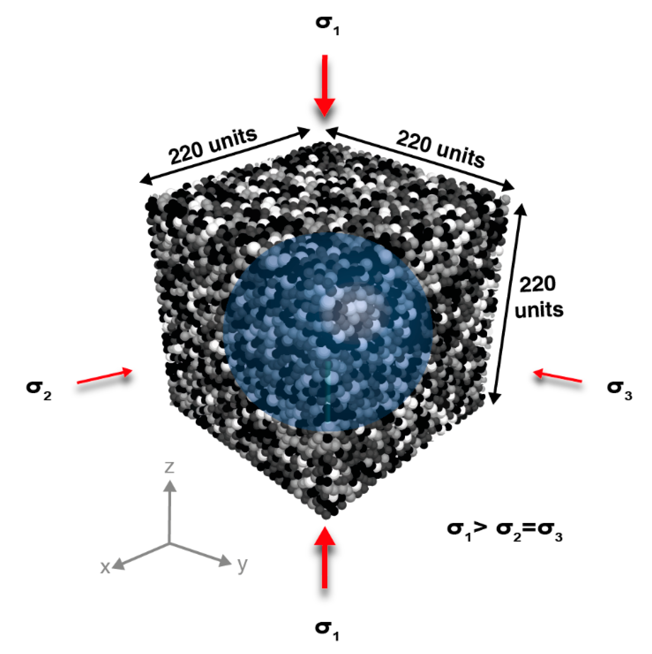
We designed the numerical triaxial cubic shear box with uniform dimensions of 220 m (Figure 2), following a simplified laboratory approach. Inside this volume, an isotropic cubic sample with equal dimensions of 220 m was generated in order to avoid sample size effects and to achieve a ratio that is at least 20× the particle size. This makes sure that the measured material macro-properties such as peak shear strength and coefficient of friction are not sensitive to particle size [42]. Each sample contained 21,172 ideal spherical particles with four different radii (R) ranging from 3.7 to 5.5 m (Table 1; Figure 2). The particles were randomly distributed within the cubic volume to produce arbitrary isotropic packing [42]. The chosen random distribution and the radius uniform spectrum prevent unrealistic deformation, such as that caused by a symmetrical particle packing [44], thus minimizing the influence of particle size and distribution on the results.
During the entire model run, solid and frictionless boundary walls confine the particles. Similar to Mair and Abe [45] and Potyondy and Cundall [42], this is done to reduce frictional boundary effects due to the interactions of particles with the walls. The walls were assigned a normal stiffness to prevent particles escaping (see k n ( wall ) and other wall properties in Table 1). Confinement effects by rigid or flexible walls were studied in 2D and 3D by Cheung and O’Sullivan [46], showing that wall rigidity is important to the post-peak behavior and particle-scale response rather than on the macro-scale. Based on these results, the current work focuses on the pre-peak and peak shear strength behavior of the material, and the effect of wall rigidity is neglected.

3.2. Particle and Bond Micro-Properties

A specific contact model was defined first to simulate either a sand-like mechanical behavior via the Hertz–Mindlin contact model or a clay-like behavior via the linear parallel-bond contact model. Independent of the specific contact model, density and coefficient of friction were defined for each particle during all triaxial tests. All particles were assigned a similar density of 2650 (kg/m³) and a constant micro- coefficient of friction of μ p = 0.5; the latter lies in the range observed for values of siliciclastic sediments [41]. Both parameters were kept constant throughout the model set-up and the entire simulation run (Table 1). The contribution of the coefficient of friction to the sediment shear strength has been extensively studied, both in laboratory tests [47,48] and DEM experiments [7,24,49]. Here, we focus on the influence of other micro-parameters—the micro shear modulus and the micro cohesive bond strength—on the cohesive and overall shear strength. In both contact models, the sliding of particles is governed by Coulomb’s friction law and is always controlled by the assigned identical constant micro coefficient of friction ( μ p ). For the Hertz–Mindlin contact model, the Poisson’s ratio was also kept constant, as it does not show a significant effect on the sediments’ mechanical behavior in the laboratory [50] or DEM tests [39]. In the linear parallel-bond contact model, we assigned the contact parameters ( k n , s ), the bond stiffness ( B n , s ), the bond friction coefficient ( μ bond ) and radius multiplier (λ) as constant values (Table 1) to minimize the amount of free micro-parameters in the model. In addition, the values of the normal and shear stiffnesses for both the contact ( k n , s ) and bond ( B n , s ) were fixed with a ratio of 1 (Table 1).

3.2.1. Hertz–Mindlin Contact Model—Granular ‘Sand-Like’ Materials

In the Hertz–Mindlin contact model, the micro-shear modulus ( G p ) was tested to investigate its influence on the numerical material’s shear strength. The values for the shear modulus (low, medium and high, Table 1) were modified from previous numerical tests to apply them to 3D simulations [7,49] and were chosen to support an elastic–plastic deformation behavior, reproducing the behavior of natural sand [51].

3.2.2. Linear Contact Bond Model—Cohesive ‘Clay-Like’ Materials

In the linear parallel-bond contact model, the two bond strength micro-parameters, the bond cohesive strength ( P B coh ) and the bond tensile strength ( P B ten ) were tested to investigate their influence on the numerical material’s cohesive and shear strength. Here, the three values tested for the bond’s strength were assigned as the ratio between the micro-cohesive bond strength ( P B coh ) and the bond micro-tensile strength ( P B ten ) was maintained around 0.5 (= P B ten / P B coh ). Cheung et al. [52] studied the effect of micro-parameters on the macro-behavior of this contact model when simulating cemented sands. Their results indicated that the overall material stiffness and peak strength are influenced by the bond-to-contact stiffnesses ratio and the size of the assigned tensile and cohesive strengths, respectively. Simulating a numerical cohesive material, Abe et al. [29] showed shallow deformational processes using a close value of tensile to cohesive strength ratio (c. 0.4). The assigned fixed values to the contact and the bond, and the tested values of the bond strength, were adjusted from previous numerical studies using the linear and parallel-bond contact models to simulate natural sedimentary rocks [7,29,53] (see Table 1).

3.3. Model Run Stages of the Numerical Triaxial Tests

The numerical confined triaxial tests were carried out in three stages: (a) sample generation, (b) isotropic compression, and (c) triaxial shear. In stage (a), particles were randomly distributed within the cubic box (an initial particle arrangement identical in all tests; Figure 2) and assigned an initial consolidation state. To simulate loose or dense initial particle consolidation states, we applied a micro- coefficient of friction ( μ ini ,   p ) to generate either a loose ( μ ini ,   p = 0.5) or a dense ( μ ini ,   p = 0.1) sample configuration. Previous studies used this approach to control the sample’s initial density [14,18,42,54]. Subsequently, the final material consolidation states were designated as L or D for loose and dense packed samples, respectively, and the material itself S or C for ‘sand’ or ‘clay’, respectively (e.g., in Table 2, densely packed ‘sand’ is DS).
In stage (b), the sample was brought to equilibrium conditions under a controlled confining stress and a controlled axial load applied by the rigid box walls. As the sample reached the assigned confining stress, the tested micro-parameters were assigned to contacts and bonds. At this point, the constant micro-friction coefficient ( μ p = 0.5) was assigned to all particles (Table 1). Each sample was tested under three magnitudes of confined stress of σ 2 = σ 3 = 100, 250 and 500 kPa. These stresses are in agreement with a wide range of laboratory tests on sandy and clayey sediments [2,28,55,56]. Triaxial tests using confining stresses higher than 1000 kPa were reported to initiate grain fracturing (e.g., [57]), which we do not attempt to simulate here.
Following the isotropic compression, the triaxial loading stage (c) was initiated. During the test, a sample was axially loaded with an increasing stress, which was symmetrically applied via the top and bottom walls ( σ 1 ; parallel to the z-axis; Figure 2). A constant velocity of 0.4 m/s was applied on the upper and lower walls and an axial strain rate of 0.00002 m/s, maintaining the quasi-static loading of the walls. This velocity is in the range of the loading velocities used in various DEM studies [58] and the relatively low axial strain rate does not influence the resulting bulk sample macro-properties e.g., [6,42,58]. The velocity of the confining walls was kept constant during the test to maintain a constant confining stress [31]. The tests were carried out until the prescribed axial strain was achieved (εz = 20%), similar to laboratory triaxial tests, e.g., [56].

3.4. Model Interpretation and Calculations

During the triaxial tests, stresses and strains were monitored continuously in the x, y, and z directions. The stress measurements were used to calculate the differential stress (i.e., the stress deviator (q)), which represents the stress under which the bulk material failed:
q = σ 1 σ 3 ,
where σ 1 and σ 3 are the maximum vertical stress and the confining stress measured and applied for each test, respectively. Combined with the associated axial strain εz, these stress–strain curves give an insight into the deformation behavior, including determination of the peak strength, strain hardening and softening effects, etc. (Figure 3a and Figure 4a).
The volumetric strain, the coordination number and the porosity (Figure 3b–d and Figure 4b–d) were monitored using a measurement sphere placed in the middle of the sample to avoid boundary effects on the measured parameters (Figure 2). The measurement sphere allowed us to measure and calculate quantities within the defined volume using the particles’ contacts and volumes [31,42]. We defined the radius of the measurement sphere as R = 90 m, which enabled us to record more than one quarter of the model volume. Such a quantity is considered representative of the entire model [59]. The quantities were then taken as averages over the volume.
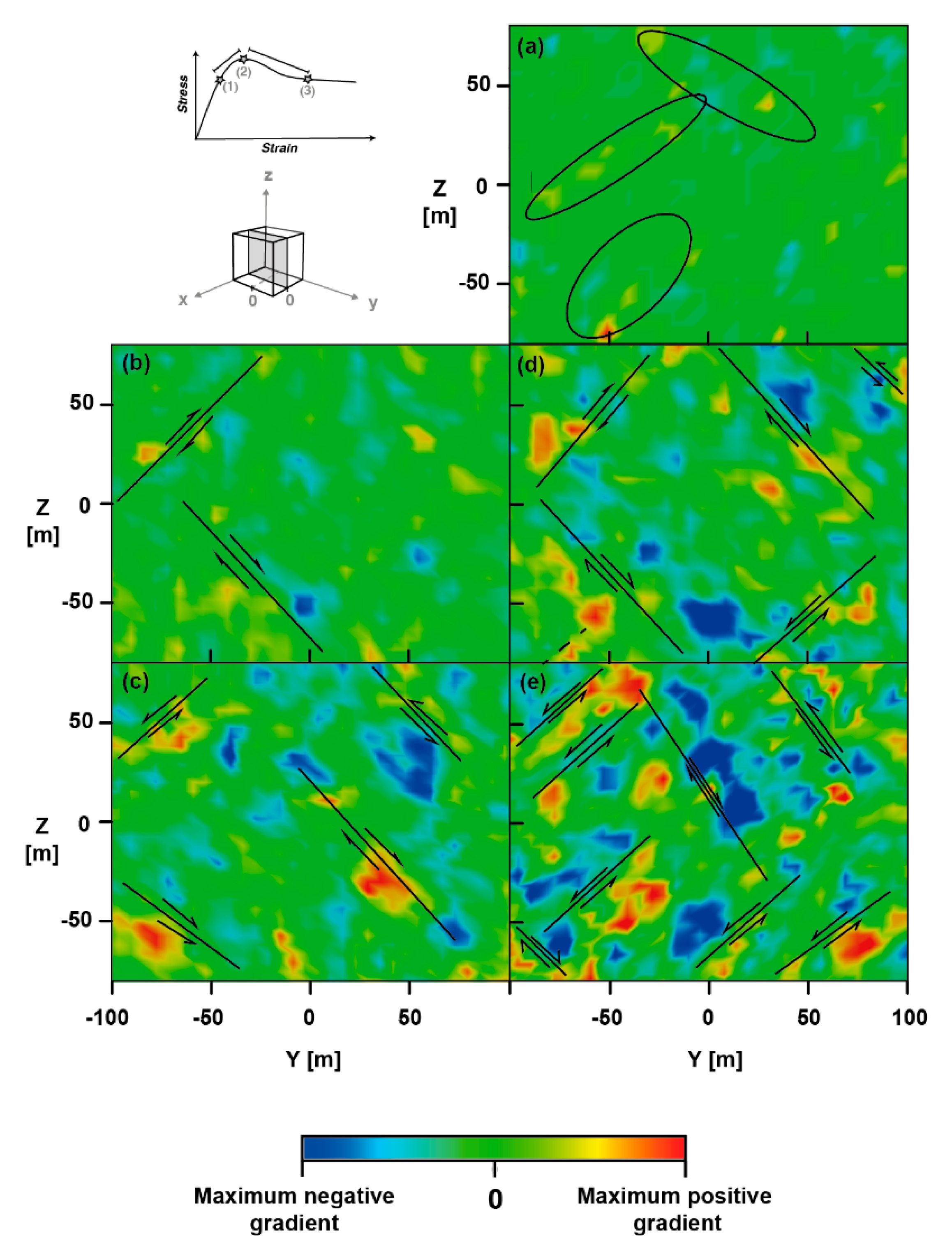
To observe significant intervals of deformation, the normalized gradient of displacement was calculated and plotted for a predefined deformation interval along a vertical cutting surface (Figure 5). This plot enables us to identify zones of high relative displacement between individual particles during a certain time interval. These zones could be interpreted as failure planes (Figure 5a–e).
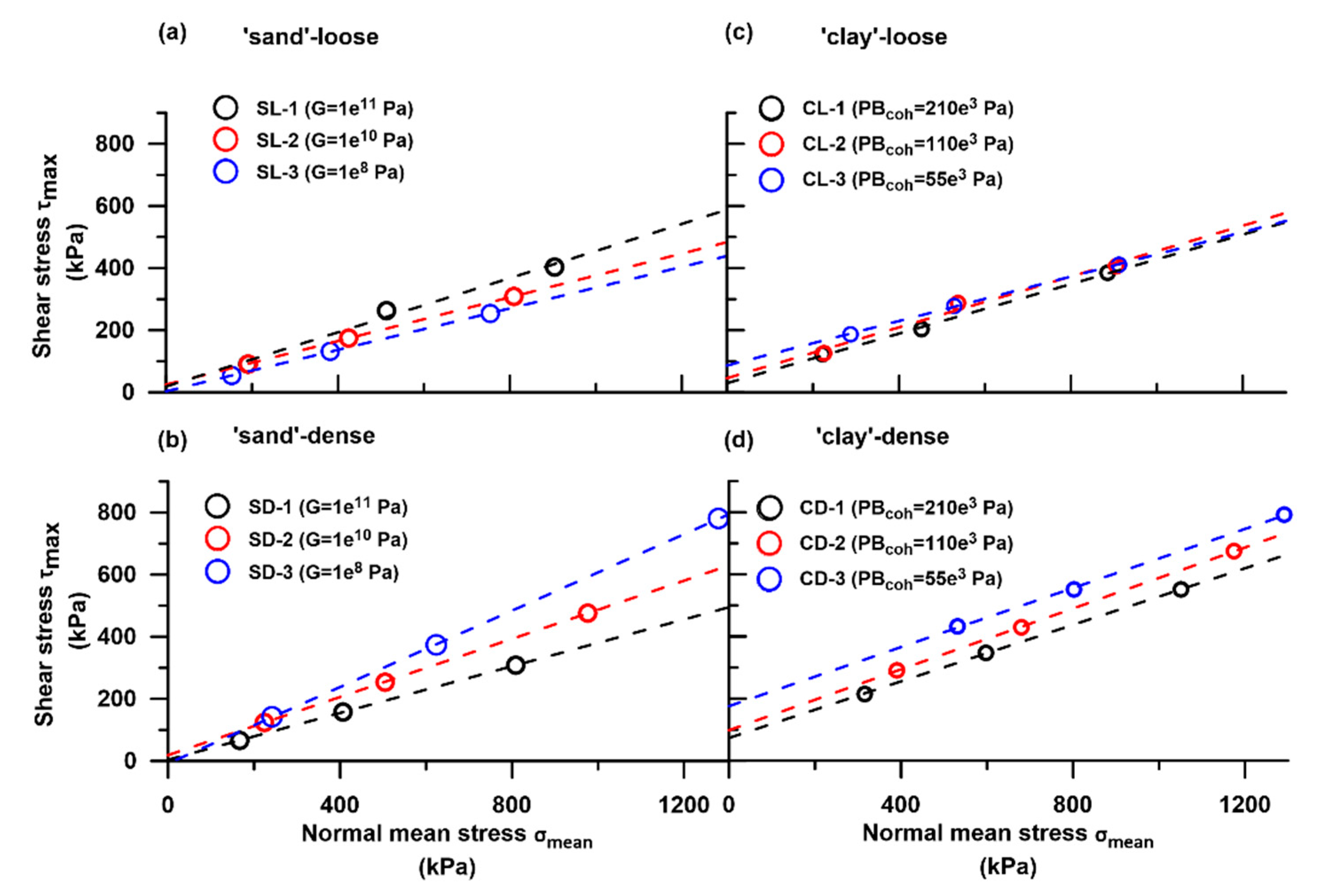
The modified failure envelope was illustrated using σ 1 and σ 3 . According to Craig [60], any state of stress can be presented by a point of stress by plotting the mean 1 2 ( σ 1 + σ 3 ) against the maximum 1 2 ( σ 1 σ 3 ) stress. The maximum shear stress and the mean normal stress were plotted in the modified failure envelope τ max σ mean space (Figure 6 and Table 2) as:
τ max = 1 2 ( σ 1 σ 3 ) ,
σ mean = 1 2 ( σ 1 + σ 3 ) ,
Note that since we performed consolidated drained tests, pore pressure was not considered and therefore the effective stress can be considered as the total stress. The peak shear strength ( τ max ), macro-friction coefficient ( μ M ) and bulk cohesion (C) for all tests are presented in Table 2 and were determined from the linear extrapolation of the modified failure envelopes. Bulk cohesion is used here in the same context as cohesion measured in laboratory experiments (over bulk material) and in Equation A4 in Appendix A.

4. Results

The 3D triaxial test results present the effect of granular contact and granular bonding ability to simulate cohesionless, sand-like and cohesive, clay-like mechanical behavior. The sensitivity of the two material endmembers was carried under different consolidation states (loose vs. dense packing) for which three different material strengths were then tested (‘sand’: G p = 1e11, 1e10, 1e8 Pa; ‘clay’: PBcoh = 55e3, 110e3, 210e3 Pa). These 12 materials were deformed under different loading conditions of 100, 250 and 500 (kPa), simulating different burial depths. In total, 36 experimental material settings were tested, 18 for each material type (Table 1).
From here onwards, the results of the Hertz–Mindlin contact model and the linear parallel-bond contact model will be referred as ‘sand’ and ‘clay’, respectively.

4.1. Stress–Strain Behavior

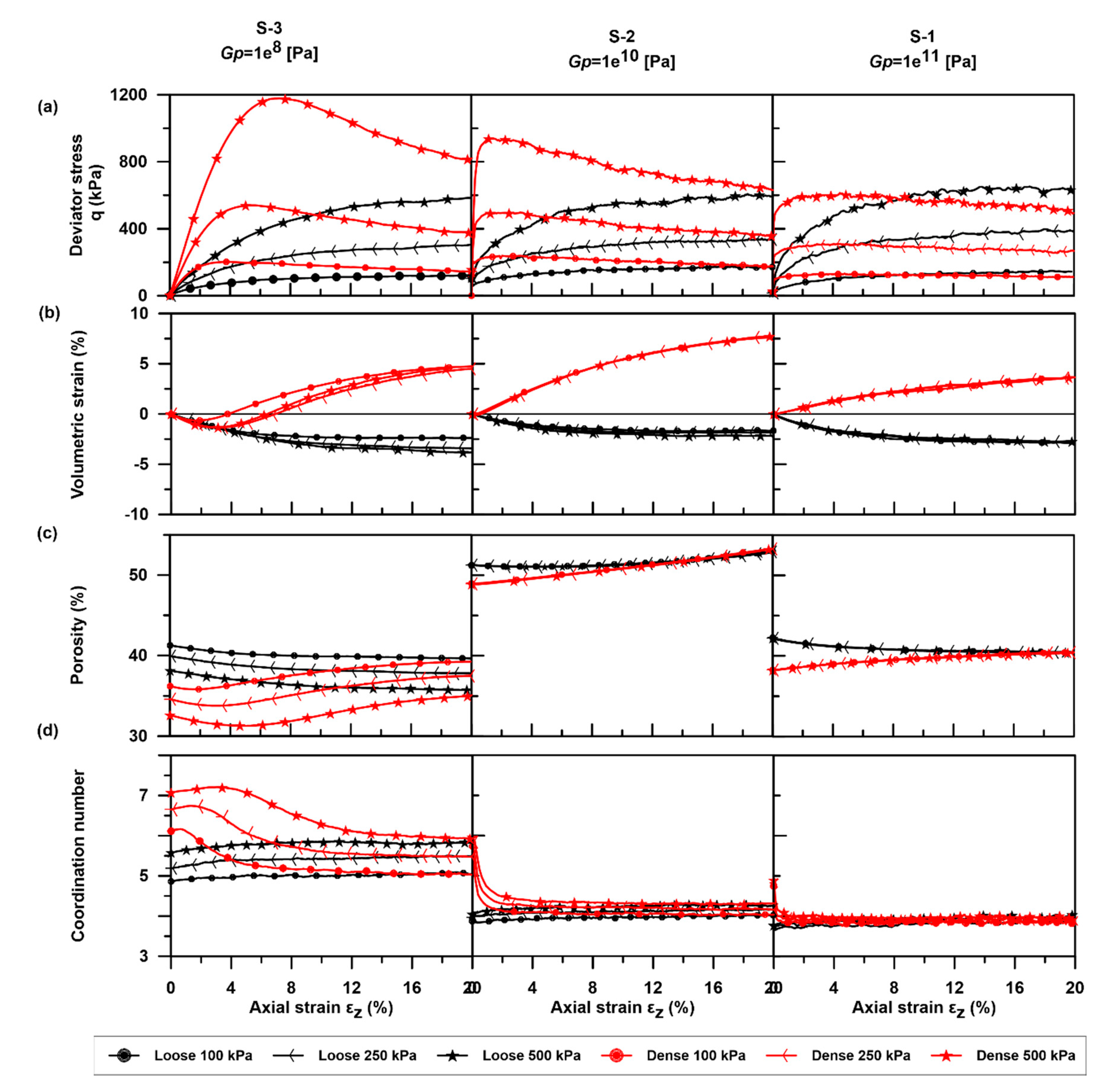
Under triaxial loading, loose ’sand’ samples showed a gradual increase in deviator stress up to 10% of axial strain (Figure 3a). The peak deviator stress, defined as the highest differential stress q (see Equation (12)), is reached between 15 to 20% of axial strain. Stress values fluctuated around this peak value. Increasing the value of the micro-shear modulus ( G p ) in the samples resulted in reaching the peak shear strength under a lower strain (in Figure 3a, G p = 1e11 Pa samples reached a peak at around 15% strain, whereas samples with G p = 1e8 Pa reached a peak only at around 17–18% strain).
The stress–strain curves of densely packed ’sand’ samples showed a rapid increase and reached the peak deviator stress at axial strains of 0.5 to 5% (Figure 3a). Following the peak, there is a rapid decrease in stress until 20% strain. These results showed that an increased micro-shear modulus ( G p ), resulted in lower peak deviator stress under lower axial strain (Figure 3a and Table 2). The opposite trend was observed in loose ’sand’ samples (an increased micro-shear modulus G p leads to an increased peak deviator stress, Table 2). A slightly different stress–strain curve of densely packed ’sand’ was observed for samples with a low micro-shear modulus ( G p = 1e8 Pa). Samples with a high micro-shear modulus show a high rate of increasing stress (Figure S2 in the Supplementary Materials), whereas samples of G p = 1e8 Pa micro-shear modulus presented a moderate rate of change in stress and reached peak deviator stress at around 2–7.5% strain.
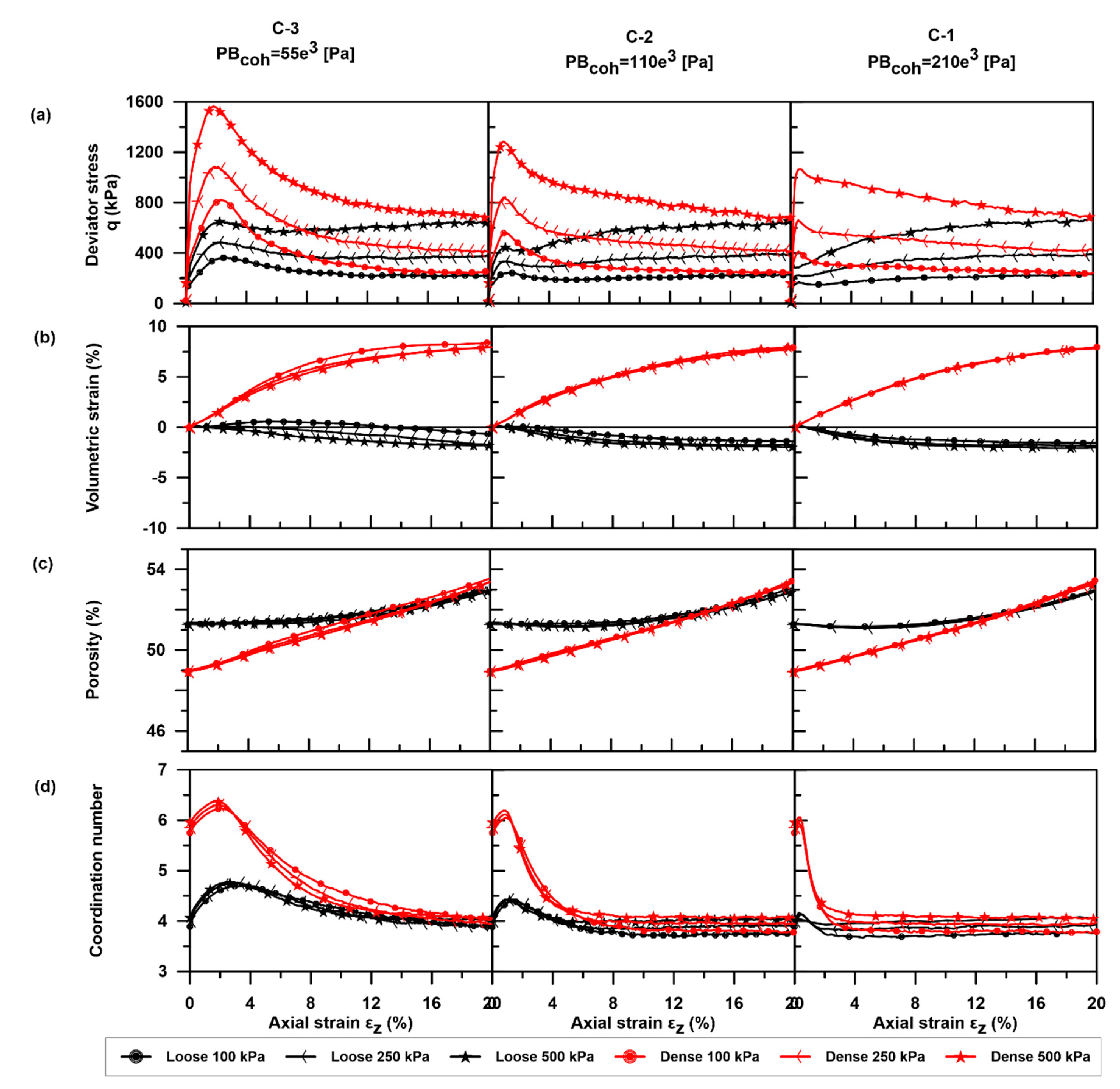
The stress–strain curves of ‘clay’ samples primarily differed from ‘sand’ due to the additional bond (Figure 4a). The results of the loose ‘clay’ samples showed a general rapid increase in the deviator stress until a peak deviator stress was reached between 0.1 and 2% of strain (Figure 4a). As the peak stress was reached, all samples presented a local variability in the rate at which the stress was changing (Figure S2 in the Supplementary Materials). Samples with low micro-cohesive bond strength ( P B coh = 55e3 Pa) showed a decrease in the residual strength (for confining stresses of 100 and 250 kPa) or a decrease followed by a slight increase up to the previous peak value (confining stress of 500 kPa). In loose ’clay’ samples, by increasing the micro-cohesive bond strength ( P B coh ), a lower peak strength was achieved under lower axial strain (rapid failure under lower stresses).
The stress–strain curves of densely packed ’clay’ samples (Figure 4a) showed a rapid increase up to peak deviator stress. The stress rate changed in a similar manner to loose ‘clay’ samples. The peak stress was reached at 0.5–2% strain, followed by a rapid decrease in stress until 20% strain was reached. Similar to loose ‘clay’ samples, a prominent peak deviator stress was observed. The stress at 20% strain is equal or slightly higher compared to the value observed for loose ’clay’ samples at 20% strain.

4.2. Volumetric Strain, Porosity and Coordination Number

Volumetric strain results for all tests are presented in Figure 3b and Figure 4b. The general trend observed for both ‘sand’ and ‘clay’ loose samples showed a nonlinear negative volumetric change—a volumetric contraction. Regardless of the value of the assigned micro-parameters in all samples, the values decreased to 2.5% of volumetric strain. An exception were the loose ’clay’ samples with low micro-cohesive bond strength ( P B coh = 55e3 Pa). The loose ’clay’ showed a slight initial increase in volumetric strain, yet after 10% of strain the trend changed and showed a decrease in volumetric strain to 1–2% (Figure 4b).
The trend of volumetric strain observed for densely packed samples was generally similar for both ‘sand’ and ‘clay’ and showed a nonlinear positive volumetric change—a volumetric dilatation. For ‘sand’ samples, the values increased up to 5% or 8% of volumetric strain (Figure 3b). For ‘clay’ samples, regardless of the value of the assigned micro-cohesive bond strength ( P B coh ), all samples showed a similar trend of volumetric increases up to 8% of volumetric strain (Figure 4b). In general, under different confining stresses, the trend observed is similar for most samples. A slightly different trend was observed for ‘sand’ samples with a low micro-shear modulus ( G p = 1e8 Pa), where a volumetric decrease was seen up to 2% of strain, followed by a volumetric strain increase.
The results observed for average porosity changes for loose ’sand’ samples showed a decrease in porosity of about 1–3% (Figure 3c) for low and high G p values, whereas, for medium G p values, little change in porosity was observed. Densely packed ’sand’ samples showed porosity changes in most samples, demonstrating an increase of 2–4%. Porosity results for samples with a low micro-shear modulus ( G p = 1e8 Pa), showed a different trend where a porosity decrease of 2% of strain was followed by a porosity increase of up to 4%. ‘Clay’ samples showed a general trend of increasing porosity. Loose ’clay’ samples showed a slight change in porosity, increasing by about 1% from the initial value. Densely packed ’clay’ samples showed a larger increase in porosity of 4% from the initial value.
Coordination numbers are presented for ‘sand’ and ‘clay’ in Figure 3d and Figure 4d, respectively, and represent the average number of contacts per particle. In general, as high strain is reached in the triaxial test (εz = 20%), most samples, regardless of their initial average coordination number, reached an average value of four contacts per particle. Loose ’sand’ samples showed a slight averaged increase in the mean coordination number of 0.2 contacts per particle. Densely packed ’sand’ samples showed a decrease in the mean coordination number of one to two contacts per particle. Exceptional behavior was observed for both loose and densely packed ‘sand’ samples with a low micro-shear modulus ( G p = 1e8 Pa), where the initial and the final mean coordination number were higher than in other samples. ‘Clay’ samples showed a similar trend for both loose and densely packed samples, which varied only in their rate of change at similar strain values. An increase in the mean coordination number (from 0.2 to 0.8 average contacts per particle) was observed under low strain (<5%). The average increase in the number of contacts per particle is inverse to the samples’ micro-cohesive bond strength ( P B coh ). The stronger the micro-cohesive bond strength ( P B coh ), the smaller the change in the mean number of contacts per particle. As strain increases (>5%), the mean coordination number decreases down to an average of four contacts per particle. The range of the decrease in the mean number of contacts per particle is of two contacts per particle for dense samples and 0.2 to 0.8 contacts per particle for loose samples. The decrease in the coordination number of both loose and densely packed ‘clays’ to a similar averaged coordination number value, is a result of bond breakage, leading to local dilation even in the loose samples, along a with similar coefficient of friction.

4.3. Strain Localization

Strain localization is observed in all samples, as indicated by the maximum positive or negative gradient of relative displacement values (Figure 5). Between the yield (1) to peak (2) stages, a low magnitude of deformation appears along the sample (Figure 5a). Elongated narrow zones of high relative displacements indicate the position of localized slip zones (Figure 5b–e; black lines).
The gradient of relative displacement in loose ’sand’ samples appears as a low magnitude of deformation of very discrete and short localized slip planes (Figure 5b). Localized deformation seems to occur at the perimeters of the sample.
In densely packed ’sand’ (Figure 5c), a higher magnitude of deformations occurs along several elongated zones. These appear as developed slip planes, with higher gradient values, which occur at the center of the sample as well.
In loose ’clay’ samples, well-defined zones of strain localization occur under smaller strain values (εz = 12%) and are limited to the perimeter of the sample (Figure 5d). As bonds break, the mode of failure alternates between slip along shear planes and focused areas of compression (Supplementary Video S3). In densely packed ’clay’ samples, strain was widely distributed within the sample with both maximum positive and negative gradient values (Figure 5e). The number of shear planes is highest in this material.
The post-peak behavior presented in all samples shows two emerging patterns that follow the pre-conditioned dense/loose packing. For loose samples, strain is localized to distinct areas in Figure 5b,d, whereas a wider area of strain localization is observed in the densely packed samples in Figure 5c,e.

5. Discussion

5.1. Parametrization of Numerical ‘Sediments’

Each tested parametrization level influenced the numerical ‘sediments’ to a different extent. The three parametrization levels—(I) endmember material strength (namely, micro-parameter G p , P B coh ), (II) burial depth and (III) initial consolidation state (loose vs. densely packed)—have first, second and third orders of influence on the material’s mechanical behavior, accordingly.
Changing an intrinsic micro-parameter affects the ability of each material to carry stress under increasing strain conditions. For loose ‘sand’ samples, higher G p contributed to an increased macroscopic coefficient of friction and a higher peak shear strength due to strain hardening (Figure 3a, Table 2). An opposite trend was observed for densely packed ‘sand’ samples. A lower peak shear strength was observed with a decrease in the macroscopic coefficient of friction due to a higher G p value. This inverse relationship could be due to a change in the micro-fabric (structure of the particles) during the confining pressure stage. Higher G p values created stiffer particles, which reduced the average contacts between particles; thus, a lower average coordination number generated fewer contact forces. This relationship between the micro-shear modulus (stiffness) and the contact forces was indicated by Lommen [61]. However, here, we additionally observed the effect of the sample packing density, which showed that, due to the initial dense consolidation state and the increase in the stiffness, the stiffer material fails under smaller strains.
Both loose and dense ‘clay’ samples presented an inverse trend to the expected impact: under higher applied micro-cohesive bond strength ( P B coh ), the resulting material failed under smaller strain levels (Figure 4a) and the shear strength and bulk cohesion decreased (Table 2). Cheung et al. [52] showed that a high bond multiplier (λ = 1, Section 3.2) resulted in an increased material stiffness and peak strength. In our experiments, we assigned a very low bond-to-contact stiffness ratio to maintain low stiffness (see Section 3.2.2); however, the results presented the opposite. We suggest that the imposed bond multiplier is the micro-parameter most likely affecting the samples’ stiffness. Overall, the ‘clay’ behavior results present an inverse relationship between the bond micro-strength and the final material strength, which results from the bond multiplier (λ). The higher assigned micro-cohesive bond strength generates a weaker material—as the bond micro-strength increases, the bulk material shows a decrease in the cohesion and peak shear stress.
The three tested confining stresses (proportional to shallow burial depth of sediments) produced, within each material setup (e.g., DS-1), an increased peak shear strength, accordingly (Table 2). Moreover, in agreement with the inverse relationship seen above for densely packed ‘sands’ and ‘clays’, higher peak shear strength values were observed in samples with lower applied micro-properties ( G p or P B coh ).
Differences between loose and dense packing are apparent from the porosity, volumetric strain and coordination number results (Figure 3b–d and Figure 4b–d). These results exhibit differences between loose and dense packing; however, no influence was observed due to changes in the confining pressure. In particular, the initial mean coordination number displays a clear difference between loose and dense ‘sediments’. In densely packed sediments, more particles are in contact than in loosely packed samples. The similar final mean coordination number (approx. 4), observed in most tests (including both dense and loose ‘sediments’), is related to (A) the uniform particle size distribution and (B) the micro coefficient of friction. The coordination number is a function of the range of particle sizes, and the ratio between the mean particle size and the smallest and biggest particle sizes. Here, this ratio was set to 30% following Saltzer and Pollard [44], i.e., the particle size distribution was uniform throughout the tests. The applied coefficient of friction was also similar in all tests, resulting in similar final mean coordination numbers and post-peak mechanical behavior (i.e., residual strength). The endmembers’ response to loose and dense packing is visible in the post-peak strain localization gradient (Figure 5) and the peak shear strength (Table 2). Loose ‘sand’ samples show deformation modes of strain hardening that are controlled mainly by compaction. The deformation appears in restricted areas of the sample, closer to the boundaries. The high stiffness and consolidation of densely packed ‘sand’, on the other hand, shows deformation controlled by dilatation. In ‘clay’ samples, both loosely and densely packed samples exhibit dilation due to bond breakage and particle movement, which are initiated under increasing stress. As stress increases, strain localization is increasingly concentrated where bonds break, and the resulting shear and deformation occurs along specific diagonal lines.

5.2. Classification of the Granular Assemblage

The ability to simulate the two endmembers’ mechanical behavior—cohesionless and cohesive—is important due to their different deformation behaviors in laboratory experiments [62]. For samples with a Hertz–Mindlin contact model, a ‘sand’-like frictional-dependent deformational behavior is observed, as the diverging failure envelopes indicate weakening due to a reduction in the friction coefficient (Table 2). For samples with a linear parallel-bond contact model, a ‘clay’-like cohesive deformational behavior is seen, as the sub-parallel failure envelopes indicate a weakening due to a reduction in cohesion (Table 2).
It should be noted that, for loose and densely packed ‘sand’ samples, bulk cohesion values were linearly extrapolated from the failure envelopes presenting low (3 kPa) to medium (33 kPa) cohesion values (see Table 2), though cohesive forces or bonds are not assigned in the Hertz–Mindlin contact model. Schellart [63] suggested that these are the result of a linear extrapolation of the Mohr–Coulomb failure envelope and that the envelope has a concave upwards shape rather than a straight line. Therefore, the extrapolated cohesion value should be neglected from the ‘sand’ samples’ macro-properties.
In some experiments, the applied micro-property is inversely proportional to the resulting macro-properties (see Table 2) and the resulting shear strength is proportional to the applied confining stress and consolidation state. Therefore, once the relationship between micro- and macro-properties is established, it is possible to use the new numerical material.
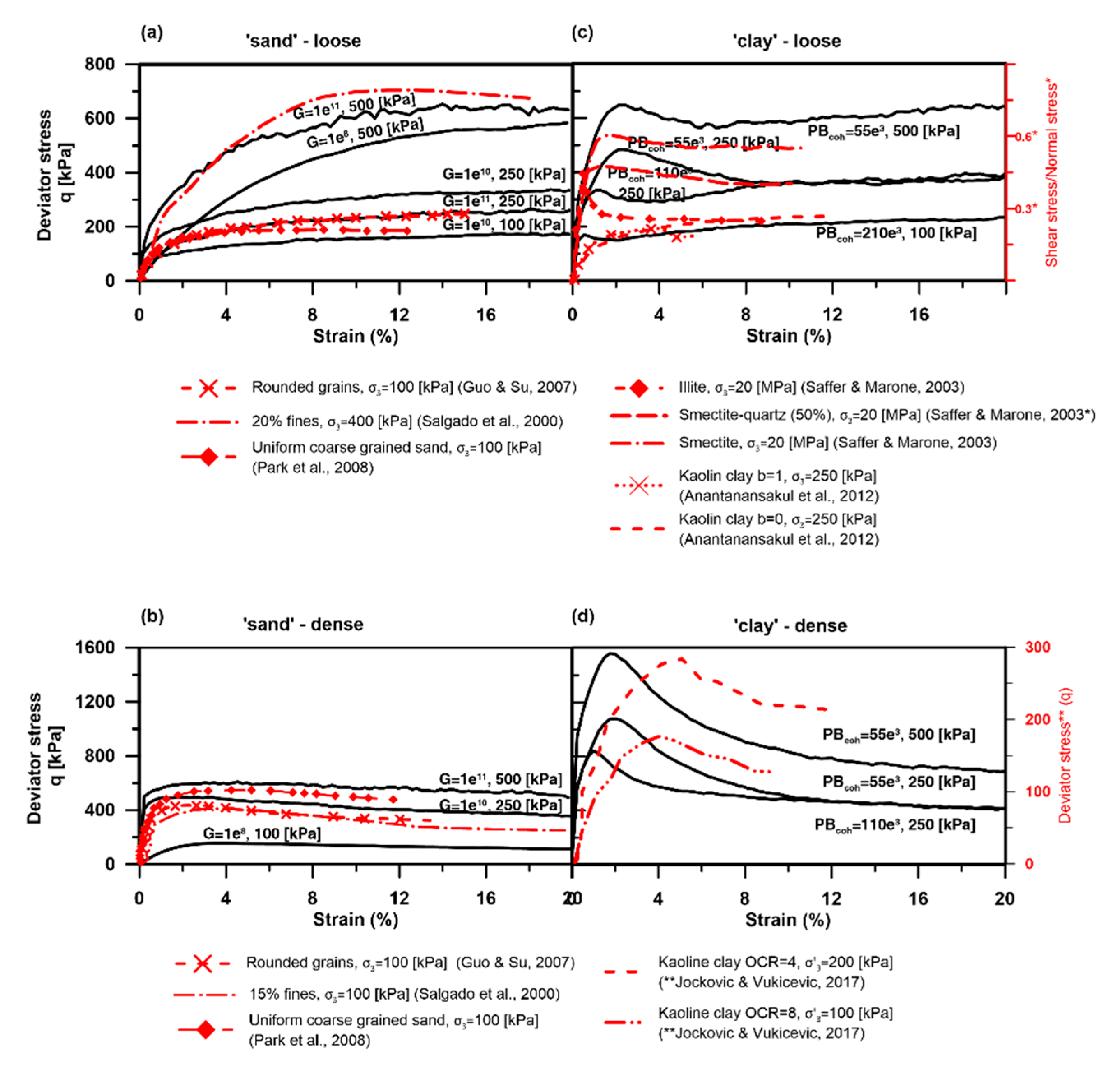
The modeled mechanical behavior is compatible with a range of results from analogue experiments, as seen in Figure 7. ‘Sand’ experiments are compared with laboratory tests (Figure 7a,b) of uniformly distributed sand (loose and densely packed) [64], rounded sand [3] and varying amounts of fines within sand [65]. This suggests that a high micro-shear modulus ( G p ) can simulate a loose, rounded and uniformly distributed sand sample under low stresses, or loose sand with up to 20% fines content under high stresses. In a densely packed state (over-consolidation), medium values of the micro-shear modulus can also be used.
The modeled loose ‘clay’ is compared with analogue tests of different normally consolidated clays [66] or normally consolidated clay particle anisotropy [30] (Figure 7c). The densely packed ‘clay’ results are compared with over-consolidated kaolinite tests exhibiting different overconsolidation ratios [67] (Over Consolidation Ratio-OCR in Figure 7d). In the ‘clay’, the applied micro-cohesive bond strength ( P B coh ) influences the timing (amount of strain) at which peak shear stress is reached. Strengthening, which appears in some of the normally consolidated ‘clay’ experiments, is analogous to the breakage of aggregates (peak) and then the reorientation of platy particles. Anantanasakul et al. [30] demonstrated that peak stress could form due to the anisotropy of kaolinite particles during deposition. As the platy clay particles are parallel or semi-parallel to the main stress ( σ 1 ), strain hardening occurs as the platy particles reorient, thus increasing shear resistance until peak shear strength is reached. The anisotropy of clayey sediments was also noted by Hicher et al. [68] as a source of increased stiffness and strength in clays.
The applied medium and low micro-cohesive bond strengths ( P B coh ) of densely packed ‘clay’ are best comparable to analogue experiments of overconsolidated clay. Empirical tests of overconsolidated (i.e., dense) clay indicate that a higher overconsolidation ratio of clay requires a lower loading stress to reach peak shear strength [67]. This is most likely due to the reorientation of the platy particles that already occurred under previous sediment loading [69], leading to a rapid and smooth transition from contractive to dilative behavior. The modeled densely packed ‘clay’ presents a comparable mechanical behavior; however, peak shear strength occurs under lower strains.
The abovementioned laboratory experiments have demonstrated the varied response of clay minerals as well as the response of intact and remolded clay to load. The primary mechanism suggested to generate failure in clay sediments is particle reorientation, forming a shear zone as the load increases [70]. However, Hattab et al. [71] proposed that the mechanism of particle reorientation also depends on the content of specific clay minerals, showing that a shear plane is more likely to develop in montmorillonite as opposed to kaolinite. The stiffer and more brittle behavior of clay also results from remolding and mottling processes [41]. Although clay particle reorientation was not simulated in our experiments, the shear strength of the modeled overconsolidated clay (i.e., dense clay) can be related to this process. Such mechanical behavior can also be used for various process simulations.

5.3. Application

The range of current simulated materials provide an opportunity to examine sediments with varying shear strengths and particle arrangements. Most commonly, in nature, post depositional processes lead to a change in shear strength. Sediments acquire their shear strength primarily from the particles’ composition (e.g., mineralogy, shape, size distribution, roughness) and the initial depositional micro-fabric [41]. Post-depositional processes affect the sediments’ shear strength due to both spatial and temporal changes in the sediments’ micro-fabric, mostly through consolidation [72]. These effects, generated in nature (due to variations in porosity, grain size distribution and friction coefficient), can be used to simulate the resulting sediments of post depositional processes and the deformation, such as discrete or distributed shear zones, as seen in Figure 5. These are applied in the form of an increased shear strength, different mechanical behavior and consolidation states.
Simulating changes in shear strength in sediments (without changes in depth or consolidation state) can be done by changing the micro-parameter G p in sand or P B coh in clay. The resulting new material can be used to simulate and compare the mechanical behaviors of sediments that experienced a change in their initial shear strength (e.g., following different levels of bioturbation in shallow sediments). A process such as bioturbation, which remolds the sediment, can modify the sediments’ shear strength [73]. During bioturbation, water is removed, and the sediment shear strength is increased [73]. Alternatively, bioturbation can break the cohesive bonds in clay sediments and lead to the decreased shear strength of the sediment [74]. Utilizing the P B coh micro-parameter also allows for the simulation of the influence of shear strength due to microbial organic [75] or calcite cement [54] following early diagenetic processes.
The numerical sediments can simulate sediments in which both shear strength and consolidation states changed post deposition (without a change in depth) by utilizing the micro-property ( G p or PBcoh) and an initial consolidation state via the initial micro- coefficient of friction ( μ p ). The new material can simulate the numerical behavior of sediments that have undergone strengthening through various actions such as waves or seismic activity, and their consolidation changes as a result of the process.
Finally, the numerical materials can simulate sediments in which shear strength is being temporally or spatially changed by utilizing all three parameters tested here, namely introducing a micro-property value ( G p or P B coh ) for a specific mechanical behavior, applying an initial consolidation state via the initial micro- coefficient of friction ( μ p ), and applying a burial depth through the initial confining pressure. Continuous or episodic depositional processes, such as changes in sedimentation rate, the loading and unloading of ice sheets due to glaciation cycles, and mass movements contribute to the increase in shear strength with time and depth. As the vertical stress grows due to increased load, sediments undergo consolidation and, consequently, the shear strength of normally consolidated sediments increases with depth almost linearly [75,76]. However, in places where a mass movement occurs, overconsolidated sediments may occur in shallow depths due to unroofing [76]. The above-presented numerical range will enable a quick setup of specific sediment behaviors for the simulation of various deformational processes in 3D.

6. Conclusions

A series of 3D triaxial numerical experiments simulated the mechanical behavior of two sediment endmembers—cohesionless and cohesive. Each endmember also presented an increased shear strength under increasing burial stress and a dense consolidation state. These results showed good agreement with laboratory tests of natural sediments under varying consolidation states and a range of compositions. It is thus suggested that the resulting shear strength in natural sediments, due to depositional and post depositional processes, can be simulated by varying the size of a micro-property (i.e., the micro-shear modulus for cohesionless sediments and micro-cohesive bond strength for cohesive sediments) without a complex particle shape or complex contact law for cohesive strength. This approach can reduce the extent of material calibration and enable studies to generate numerical sediments according to a desired process and geological history (i.e., to generate sediments that have undergone increasing or decreasing shear strength processes).
In order to apply our results in future simulations of sediments, one to three levels of parametrization should be used. The level of parametrization sets the order of influence of the sediments’ mechanical behavior under an applied stress. Prior to the parametrization, the appropriate contact model should be considered and set to produce cohesionless or cohesive numerical sediments.
In order to simulate sediments with the first order of influence (i.e., material shear strength), it is recommended to apply a high or a low micro-parameter ( G p for sands and PBcoh for clays). This will enable the simulation of shallow sediments, for which only shear strength has changed—such as inherited shear strength due to original deposited sediment micro-fabric, or shear strength altered by bioturbation or early digenesis cementation.
In order to simulate sediments with a second order of influence (i.e., consolidation), it is recommended to use both the initial micro coefficient of friction to generate loose or dense sediment packing and, additionally, to apply a high or low micro-parameter. This parametrization simulates sediments for which a change in consolidation state has also occurred—volumetric change as well as a change in shear strength, such as after a strengthening event.
In order to simulate sediments with a third order of influence—burial depth—it is recommended to use all three parameters, i.e., the abovementioned parameters and a confining stress appropriate to the burial depth. This parametrization simulates sediments for which a change in the burial depth or a cycle of burial and exposure has occurred, such as after deglaciation or a mass movement event.

Supplementary Materials

The following are available online at https://www.mdpi.com/2227-9717/8/10/1252/s1, Figure S1: Self-similarity test, Figure S2: Stress rate, Video S1: Sample LS-2 3D deformation, Video S2: Sample DS-2 3D deformation, Video S3: Sample LC-2 3D deformation, Video S4: Sample DC-2 3D deformation.

Author Contributions

Conceptualization, H.E. and K.H.; methodology, H.E. and L.S.; validation, H.E. and L.S.; formal analysis, H.E.; writing—original draft preparation, H.E.; writing—review and editing, H.E.; K.H.; R.B.; L.S.; and U.t.B.; visualization, H.E.; supervision, K.H; R.B. and U.t.B. All authors have read and agreed to the published version of the manuscript.

Funding

This research received no external funding.

Acknowledgments

HE would like to thank Jannis Kuhlmann and Ricarda Gatter for their review and valuable comments. In addition, we thank Adrian Garcia and three anonymous reviewers for their useful comments. Use of trade, product, or firm names is for descriptive purposes only and does not imply endorsement by the U.S. government.

Conflicts of Interest

The authors declare no conflict of interest.

Appendix A. DEM Force–Displacement Calculation

Particles that interact are allowed to overlap according to the soft particle approach, in which, geometrically, particles remain rigid and only small deformations occur at contact points [7,30]. The particle properties as well as the applied boundary conditions, e.g., gravity, determine the magnitude of the particles’ overlap ( δ , Figure 1), which, in turn, is used to calculate the forces that act on individual particle contacts. Each contact relates to both the normal F n and tangential F s forces.
The forces are calculated for 3D spheres in the case of an elastoplastic contact model or material behavior, respectively [8,30], via:
F n = k p   ( n ) · δ n 3 / 2 ,
F s = k p   ( s ) · δ s 3 / 2 ,
where F n and F s are the normal and tangential forces acting at each particle contact point; k n , p and k s , p are the normal and tangential stiffnesses, respectively, and δ n 3 / 2 and δ s 3 / 2 are the particle overlap in the normal and tangential directions as well (Figure 1).
To evaluate the subsequent motion of a particle, Newton’s second law is used. Therefore, all normal F n and shear F s forces are summed up for each individual particle to calculate a so-called net force F n which than reveals the acceleration and potential subsequent displacement of each individual particle. As the calculation is repeated, in order to dissipate the energy in the system, at each time step, a local damping component (Table 1, damp) is applied.
To allow particle contacts to break and subsequently let particles slip one past the other, a slip condition is introduced. The slip condition is defined as a critical shear force value F s   ( max ) , which, once exceeded, means that slip will occur:
F s   ( max ) = μ p · F n ,
where F n is the normal force at a contact point and μ p is the minimum friction coefficient of the two particles in contact. It should be noted that the shear forces at each contact point add up at each calculation step. When the added shear force is F s , p > F s   ( max ) , sliding occurs between two particles and the contact breaks. Following this, it is possible to evaluate the maximum shear stress of the bulk numerical material (the overall particles assemblage) via the Mohr–Coulomb criterion:
τ   ( max ) = C + ( μ · σ n ) ,
where τ   ( max ) is the maximum shear strength the bulk material can sustain, C is the cohesion, μ is the bulk material friction coefficient and σ n is the normal stress.
To summarize, in each calculation step, the simulation starts by detecting particles that are in contact. The forces exerted by particles are then calculated according to selected contact models based on the particles’ overlap and micro-properties via Equations (A1) and (A2). The newly calculated contact forces are combined for each particle and used to calculate subsequent particle movements based on Newton’s second law of motion:
F N = ρ p ( 4 3 ) π R p 3 a ,
where ρ p is a particle’s density, R p is a particle’s radius and a is the acceleration. Particles’ velocity and displacement, as well as the resultant new particle contacts, are updated at the end of each iteration [30].

References

  1. Ikari, M.J.; Kopf, A.J. Cohesive strength of clay-rich sediment. Geophys. Res. Lett. 2011, 38, 1–5. [Google Scholar] [CrossRef]
  2. Hattab, M.; Hammad, T.; Fleureau, J.M.; Hicher, P.Y. Behaviour of a sensitive marine sediment: Microstructural investigation. Géotechnique 2013, 63, 71–84. [Google Scholar] [CrossRef] [Green Version]
  3. Guo, P.; Su, X. Shear strength, interparticle locking, and dilatancy of granular materials. Can. Geotech. J. 2007, 44, 579–591. [Google Scholar] [CrossRef]
  4. van Gent, H.W.; Holland, M.; Urai, J.L.; Loosveld, R. Evolution of fault zones in carbonates with mechanical stratigraphy - Insights from scale models using layered cohesive powder. J. Struct. Geol. 2010, 32, 1375–1391. [Google Scholar] [CrossRef]
  5. Kinoshita, M.; Tobin, H.; Ashi, J.; Kimura, G.; Lallemant, S.; Screaton, E.J.; Curewitz, D.; Masago, H.; Moe, K.T. Data report: Permeability, compressibility, stress state, and grain size of shallow sediments from Sites C0004, C0006, C0007, and C0008 of the Nankai accretionary complex. Proc. IODP. 2011, 314, 2. [Google Scholar]
  6. LongJohn, T.; Morgan, J.K.; Dugan, B. Microstructural Evolution of Porosity and Stress During the Formation of Brittle Shear Fractures: A Discrete Element Model Study. J. Geophys. Res. Solid Earth 2018, 123, 2228–2245. [Google Scholar] [CrossRef] [Green Version]
  7. Kock, I.; Huhn, K. Influence of particle shape on the frictional strength of sediments—A numerical case study. Sediment. Geol. 2007, 196, 217–233. [Google Scholar] [CrossRef]
  8. Cundall, P.A.; Strack, O.D.L. BALL–A program to model granular media using the distinct element method. In Technical Note; Advance Technology Group, Dames and Moore: London, UK, 1978; pp. 129–163. [Google Scholar]
  9. Miyakawa, A.; Yamada, Y.; Matsuoka, T. Effect of increased shear stress along a plate boundary fault on the formation of an out-of-sequence thrust and a break in surface slope within an accretionary wedge, based on numerical simulations. Tectonophysics 2010, 484, 127–138. [Google Scholar] [CrossRef]
  10. Campbell, C.S.; Cleary, P.W.; Hopkins, M. Large-scale landslide simulations: Global deformation, velocities and basal friction. J. Geophys. Res. 1995, 100, 8267. [Google Scholar] [CrossRef]
  11. Mair, K.; Abe, S. 3D numerical simulations of fault gouge evolution during shear: Grain size reduction and strain localization. Earth Planet. Sci. Lett. 2008, 274, 72–81. [Google Scholar] [CrossRef] [Green Version]
  12. Cundall, P.A.; Strack, O.D.L. A dicrete numerical model for granular assemblies. Geotechnique 1979, 29, 47–65. [Google Scholar] [CrossRef]
  13. Wenk, L.; Huhn, K. The influence of an embedded viscoelastic–plastic layer on kinematics and mass transport pattern within accretionary wedges. Tectonophysics 2013, 608, 653–666. [Google Scholar] [CrossRef]
  14. Morgan, J.K. Numerical simulations of granular shear zones using the distinct element method: 2. Effects of particle size distribution and interparticle friction on mechanical behavior. J. Geophys. Res. Solid Earth 1999, 104, 2721–2732. [Google Scholar] [CrossRef]
  15. Santamarina, J.; Shin, H. Friction in granular media. Meso-Scale Shear Phys. Earthq. Landslide Mech. 2009, 159–190. [Google Scholar] [CrossRef]
  16. Rothenburg, L.; Bathurst, R.J. Micromechanical features of granular assemblies with planar elliptical particles. Geotechnique 1992, 42, 79–95. [Google Scholar] [CrossRef]
  17. Rothenburg, L.; Bathurst, R.J. Influence of particle eccentricity on micromechanical behavior of granular materials. Mech. Mater. 1993, 16, 141–152. [Google Scholar] [CrossRef]
  18. Thornton, C. Numerical simulations of deviatoric shear deformation of granular media. Géotechnique 2000, 50, 43. [Google Scholar] [CrossRef]
  19. Guo, Y.; Morgan, J.K. Influence of normal stress and grain shape on granular friction: Results of discrete element simulations. J. Geophys. Res. Solid Earth 2004, 109, 1–16. [Google Scholar] [CrossRef] [Green Version]
  20. Schöpfer, M.P.J.; Abe, S.; Childs, C.; Walsh, J.J. The impact of porosity and crack density on the elasticity, strength and friction of cohesive granular materials: Insights from DEM modelling. Int. J. Rock Mech. Min. Sci. 2009, 46, 250–261. [Google Scholar] [CrossRef] [Green Version]
  21. Kuhn, M.R. Smooth convex three-dimensional particle for the discrete-element method. J. Eng. Mech. 2003, 129, 539–547. [Google Scholar] [CrossRef]
  22. Iwashita, K.; Oda, M. Mechanics of Granular Materials: An Introduction; A.A. Balkema: Rotterdam, The Netherlands, 1999. [Google Scholar]
  23. Mora, P.; Place, D. Simulation of the frictional stick-slip instability. Pure Appl. Geophys. 1994, 143, 61–87. [Google Scholar] [CrossRef]
  24. Morgan, J.K.; Boettcher, M.K. Numerical simulations of granular shear zones using the distinct element method 1. Shear zone kinematics and the micromechanics of localization. J. Geophys. Res. 1999, 104, 2703–2719. [Google Scholar] [CrossRef]
  25. Antonellini, M.A.; Pollard, D.D. Distinct element modeling of deformation bands in sandstone. J. Struct. Geol. 1995, 17, 1165–1182. [Google Scholar] [CrossRef]
  26. Ask, M.V.S.; Kopf, A. Constraints on the state of in situ effective stress and the mechanical behavior of ODP Leg 186 claystones in the Japan Trench forearc. Isl. Arc 2004, 13, 242–257. [Google Scholar] [CrossRef]
  27. Mair, K.; Frye, K.M.; Marone, C. Influence of grain characteristics on the friction of granular shear zones. J. Geophys. Res. Solid Earth 2002, 107, ECV 4-1–ECV 4-9. [Google Scholar] [CrossRef]
  28. Yamamuro, J.A.; Abrantes, A.E.; Lade, P.V. Effect of Strain Rate on the Stress-Strain Behavior of Sand. J. Geotech. Geoenviron. Eng. 2011, 137, 1169–1178. [Google Scholar] [CrossRef]
  29. Abe, S.; van Gent, H.; Urai, J.L. DEM simulation of normal faults in cohesive materials. Tectonophysics 2011, 512, 12–21. [Google Scholar] [CrossRef]
  30. Anantanasakul, P.; Yamamuro, J.A.; Lade, P.V. Three-dimensional drained behavior of normally consolidated anisotropic kaolin clay. Soils Found. 2012, 52, 146–159. [Google Scholar] [CrossRef] [Green Version]
  31. Itasca Consulting Group Inc. PFC—Particle Flow Code, Ver. 5.0; Itasca Consulting Group Inc.: Minneapolis, MN, USA, 2014. [Google Scholar]
  32. Sadek, M.A.; Chen, Y.; Liu, J. Simulating shear behavior of a sandy soil under different soil conditions. J. Terramech. 2011, 48, 451–458. [Google Scholar] [CrossRef]
  33. Potyondy, D.O. The bonded-particle model as a tool for rock mechanics research and application: Current trends and future directions. Geosyst. Eng. 2015, 18, 1–28. [Google Scholar] [CrossRef]
  34. Huhn, K.; Kock, I.; Kopf, A.J. Comparative numerical and analogue shear box experiments and their implications for the mechanics along the failure plane of landslides. Nor. Geol. Tidsskr. 2006, 86, 209–220. [Google Scholar]
  35. Pichel, L.M.; Finch, E.; Gawthorpe, R.L. The Impact of Pre-Salt Rift Topography on Salt Tectonics: A Discrete-Element Modeling Approach. Tectonics 2019, 38, 1466–1488. [Google Scholar] [CrossRef] [Green Version]
  36. Wang, Q.J.; Zhu, D. Hertz Theory: Contact of Spherical Surfaces. In Encyclopedia of Tribology; Wang, Q.J., Chung, Y.-W., Eds.; Springer: Boston, MA, USA, 2013; ISBN 978-0-387-92896-8. [Google Scholar]
  37. Mindlin, R.D.; Deresiewicz, H. Elastic Spheres in Contact under Varying Oblique Forces. J. Appl. Mech. 1953, 20, 327–344. [Google Scholar]
  38. Yimsiri, S.; Soga, K. Effects of soil fabric on behaviors of granular soils: Microscopic modeling. Comput. Geotech. 2011, 38, 861–874. [Google Scholar] [CrossRef]
  39. Manchanda, R.; Olson, J.E.; Sharma, M.M. Mechanical, failure and flow properties of sands: Micro-mechanical models. 46th US Rock Mech. Geomech. Symp. 2012 2012, 3, 1555–1569. [Google Scholar]
  40. Yamamoto, T.; Nye, T.; Kuru, M. Porosity, permeability, shear strength: Crosswell tomography below an iron foundry. Geophysics 1994, 59, 1530–1541. [Google Scholar] [CrossRef]
  41. Mitchell, J.K.; Soga, K. Fundamentals of Soil Behavior, 3rd ed.; John Wiley & Sons: Hoboken, NJ, USA, 2005. [Google Scholar]
  42. Potyondy, D.O.; Cundall, P.A. A bonded-particle model for rock. Int. J. Rock Mech. Min. Sci. 2004, 41, 1329–1364. [Google Scholar] [CrossRef]
  43. Gylland, A.S.; Rueslåtten, H.; Jostad, H.P.; Nordal, S. Microstructural observations of shear zones in sensitive clay. Eng. Geol. 2013, 163, 75–88. [Google Scholar] [CrossRef]
  44. Saltzer, S.D.; Pollard, D.D. Distinct element modeling of structures formed in sedimentary overburden by extensional reactivation of basement normal faults. Tectonics 1992, 11, 165–174. [Google Scholar] [CrossRef]
  45. Mair, K.; Abe, S. Breaking Up: Comminution Mechanisms in Sheared Simulated Fault Gouge. Pure Appl. Geophys. 2011, 168, 2277–2288. [Google Scholar] [CrossRef] [Green Version]
  46. Cheung, G.; O’Sullivan, C. Effective simulation of flexible lateral boundaries in two- and three-dimensional DEM simulations. Particuology 2008, 6, 483–500. [Google Scholar] [CrossRef]
  47. Morrow, C.A.; Moore, D.E.; Lockner, D.A. Frictional strength of wet and dry montmorillonite. J. Geophys. Res. Solid Earth 2017, 122, 3392–3409. [Google Scholar] [CrossRef]
  48. Rathbun, A.P.; Marone, C. Effect of strain localization on frictional behavior of sheared granular materials. J. Geophys. Res. 2010, 115, 1–16. [Google Scholar] [CrossRef]
  49. Kock, I.; Huhn, K. Numerical investigation of localization and micromechanics in a stratified soil specimen. J. Struct. Geol. 2007, 29, 1679–1694. [Google Scholar] [CrossRef]
  50. Nandanwar, M.; Chen, Y. Modeling and measurements of triaxial tests for a sandy loam soil. Can. Biosyst. Eng. 2017, 59, 2.1–2.8. [Google Scholar] [CrossRef] [Green Version]
  51. Turcotte, D.; Schubert, G. Geodynamics; Cambridge University Press: Cambridge, UK, 2014. [Google Scholar]
  52. Cheung, L.Y.G.; O’Sullivan, C.; Coop, M.R. Discrete element method simulations of analogue reservoir sandstones. Int. J. Rock Mech. Min. Sci. 2013, 63, 93–103. [Google Scholar] [CrossRef]
  53. Huhn, K.; Strozyk, F.; Kock, I. Quantifying the key role of slope material peak strength–using discrete element simulations. In Proceedings of the Submarine Mass Movements and their Consequences; Springer: Cham, Switzerland, 2016; pp. 537–545. [Google Scholar]
  54. Feng, K.; Montoya, B.M.; Evans, T.M. Discrete element method simulations of bio-cemented sands. Comput. Geotech. 2017, 85, 139–150. [Google Scholar] [CrossRef] [Green Version]
  55. Marri, A.; Wanatowski, D.; Yu, H.S. Drained behaviour of cemented sand in high pressure triaxial compression tests. Geomech. Geoeng. 2012, 7, 159–174. [Google Scholar] [CrossRef]
  56. Wanatowski, D.; Chu, J. Drained behaviour of Changi sand in triaxial and plane-strain compression. Geomech. Geoeng. 2008, 3, 85–96. [Google Scholar] [CrossRef]
  57. De Bono, J.P.; McDowell, G.R. DEM of triaxial tests on crushable sand. Granul. Matter 2014, 16, 551–562. [Google Scholar] [CrossRef] [Green Version]
  58. Ding, X.; Zhang, L.; Zhu, H.; Zhang, Q. Effect of Model Scale and Particle Size Distribution on PFC3D Simulation Results. Rock Mech. Rock Eng. 2014, 47, 2139–2156. [Google Scholar] [CrossRef]
  59. Schöpfer, M.P.J.; Childs, C.; Manzocchi, T. Three-dimensional failure envelopes and the brittle-ductile transition. J. Geophys. Res. Solid Earth 2013, 118, 1378–1392. [Google Scholar] [CrossRef]
  60. Craig, R.F. Craig’s Soil Mechanics; CRC Press: New-York, USA, 2004. [Google Scholar]
  61. Lommen, S.; Schott, D.; Lodewijks, G. DEM speedup: Stiffness effects on behavior of bulk material. Particuology 2014, 12, 107–112. [Google Scholar] [CrossRef]
  62. Eisenstadt, G.; Sims, D. Evaluating sand and clay models: Do rheological differences matter? J. Struct. Geol. 2005, 27, 1399–1412. [Google Scholar] [CrossRef]
  63. Schellart, W.P. Shear test results for cohesion and friction coefficients for different granular materials: Scaling implications for their usage in analogue modelling. Tectonophysics 2000, 324, 1–16. [Google Scholar] [CrossRef]
  64. Park, L.K.; Suneel, M.; Chul, I.J. Shear strength of jumunjin sand according to relative density. Mar. Georesources Geotechnol. 2008, 26, 101–110. [Google Scholar] [CrossRef]
  65. Salgado, R.; Bandini, P.; Karim, A. Shear strength and stiffness of silty sand. J. Geotech. Geoenviron. Eng. 2000, 126, 451–462. [Google Scholar] [CrossRef]
  66. Saffer, D.M.; Marone, C. Comparison of smectite- and illite-rich gouge frictional properties: Application to the updip limit of the seismogenic zone along subduction megathrusts. Earth Planet. Sci. Lett. 2003, 215, 219–235. [Google Scholar] [CrossRef]
  67. Jocković, S.; Vukićević, M. Bounding surface model for overconsolidated clays with new state parameter formulation of hardening rule. Comput. Geotech. 2017, 83, 16–29. [Google Scholar] [CrossRef]
  68. Hicher, P.Y.; Wahyudi, H.; Tessier, D. Microstructural analysis of inherent and induced anisotropy in clay. Mech. Cohesive-Frict. Mater. 2000, 5, 341–371. [Google Scholar] [CrossRef]
  69. Hattab, M.; Fleureau, J.M. Experimental study of kaolin particle orientation mechanism. Geotechnique 2010, 60, 323–331. [Google Scholar] [CrossRef]
  70. Djéran-Maigre, I.; Tessier, D.; Grunberger, D.; Velde, B.; Vasseur, G. Evolution of microstructures and of macroscopic properties of some clays during experimental compaction. Mar. Pet. Geol. 1998, 15, 109–128. [Google Scholar] [CrossRef]
  71. Hattab, M.; Hammad, T.; Fleureau, J.M. Internal friction angle variation in a kaolin/montmorillonite clay mix and microstructural identification. Geotechnique 2015, 65, 1–11. [Google Scholar] [CrossRef]
  72. Bennett, R.H.; Bryant, W.R.; Keller, G.H. Clay Fabric of Selected Submarine Sediments: Fundamental Properties and Models. Sepm J. Sediment. Res. 1981, 51, 217–232. [Google Scholar]
  73. Locat, J.; Lee, H.; Kayen, R.; Israel, K.; Savoie, M.C.; Boulanger, É. Shear strength development with burial in Eel River margin slope sediments. Mar. Georesources Geotechnol. 2002, 20, 111–135. [Google Scholar] [CrossRef]
  74. Davis, W.R. The role of bioturbation in sediment resuspension and its interaction with physical shearing. J. Exp. Mar. Biol. Ecol. 1993, 171, 187–200. [Google Scholar] [CrossRef]
  75. Perret, D.; Locat, J.; Leroueil, S. Strength development with burial in fine-grained sediments from the Seguenay Fhord, Quebec. Can. Geotech. J. 1995, 32, 247–262. [Google Scholar] [CrossRef]
  76. Ikari, M.J.; Kopf, A.J. The role of cohesion and overconsolidation in submarine slope failure. Mar. Geol. 2015, 369, 153–161. [Google Scholar] [CrossRef]
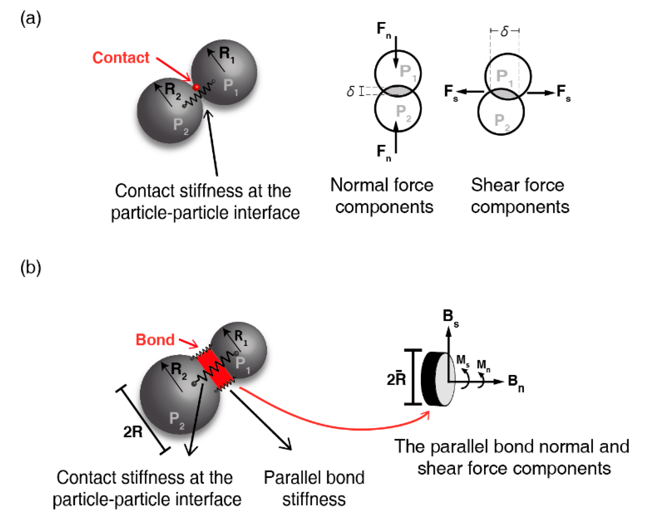
Figure 1. (a) An illustration of particles interaction according to the Hertz–Mindlin contact model. (Left) The contact point is illustrated as a red sphere and the contact stiffness as a spring. R1 and R2 represent the radii of particles P1 and P2, accordingly. (Right) A 2D cross section of the acting normal ( F n ) and shear ( F s ) forces and the particle’s overlapping δ. (b) An illustration of particles interaction according to the linear parallel-bond contact model. (Left) In addition to a contact at the interacting point of two particles (contact stiffness presented as a spring), a bond is implemented as a cylindrical disk (in red), and its interaction is illustrated by two parallel springs. R1 and R2 represent the radius of particles P1 and P2, accordingly. (Right) A 3D illustration of the bond’s normal (Bn) and shear (Bs) forces and the moments (Mn and Ms) that result from the applied force. The size of the applied bond is according to the average radius of the two interacting particles and represented as an average 2R.
Processes 08 01252 g001
Figure 2. The 3D Discrete Element Method (DEM) cubic isotropic sample. The initial particle setup for the triaxial test are under strain (εz) = 0%. The blue sphere in the center of the pre-tested cubic sample presents the location of the measurement sphere. The main stress (σ1) is acting parallel to the z-axis; σ 2 and σ 3 are equal and act parallel to axes x and y, respectively.
Processes 08 01252 g002
Figure 3. Triaxial tests results for ‘sand’ samples presented as (a) the deviator stress, (b) the volumetric strain, (c) the porosity and (d) the coordination number over the axial strain; the micro-shear modulus ( G p ) is increasing from left to right. Black lines represent loose packed samples and red lines represent dense packed samples. Each confining stress is represented by a different symbol for 100, 250 and 500 kPa.
Processes 08 01252 g003
Figure 4. Triaxial tests results for ‘clay’ samples presented as (a) the deviator stress, (b) the volumetric strain, (c) the porosity and (d) the coordination number over the axial strain; the micro-cohesive bond strength ( P B coh ) is increasing from left to right. Black lines represent loose packed samples and red lines represent dense packed samples. Each confining stress is represented by a different symbol for 100, 250 and 500 kPa.
Processes 08 01252 g004
Figure 5. Strain localization visualized for deformation stages. Deformation stages are defined between points (1) and (3) along a typical stress–strain curve, where (1) is the yield stress, (2) the peak stress and (3) the post-peak situation. Deformation is imaged along a vertical cross section of the 3D test (location indicated by the grey cross section). (a) Initiation of strain localization highlighted by oval circles (between stages 1 and 2, Experiment DC-2). Localization is presented for four samples tested under confining stress σ2,3 = 250 kPa. (b) Experiment LS-2, loose ’sand’ ( G p = 1e10 Pa) taken after 17% of strain (c) Experiment DS-2, dense ’sand’ ( G p = 1e10 Pa) taken after 17% of strain. (d) Experiment LC-2, loose ’clay’ ( P B coh = 110e3 Pa) taken after 12% of strain. (e) Experiment DC-2, dense ’clay’ ( P B coh = 110e3 Pa) taken after 12% of strain. Black lines indicate selected areas of strain localization further explained in the text.
Processes 08 01252 g005
Figure 6. Modified Mohr–Coulomb failure envelopes for (a) loose ’sand’ (b) dense ’sand’ (c) loose ’clay’ and (d) dense ’clay’ samples. Circles denote the differential peak shear strength measured in each test under the appropriate normal stress.
Processes 08 01252 g006
Figure 7. A comparison between the mechanical behavior (stress–strain) of the numerical results and laboratory experiments of sediments. Laboratory experiments of loose and dense sands and normally consolidated and overconsolidated clays are respectively compared to the numerical results. (a) loose ‘sand’ (b) dense ‘sand’ (c) loose ‘clay’ (d) dense ‘clay’. Solid black lines are results from the DEM simulations, found to resemble empirical lab results. Above each line, the micro-parameter size and confining stress are detailed. Dashed and dotted red lines are results of empirical triaxial tests on natural sediments. Data from Guo and Su [3] were recalculated to fit the deviatoric stress axis. For other data ([65,66]), the original y-axis is present on the right-hand side (red labels).
Processes 08 01252 g007
Table 1. Fixed and tested micro-parameters applied in each of the triaxial tests according to the contact model applied during the test.
ParametersUnit of MeasureSymbolValue
Fixed Properties
Sample dimensions: width; height; length (m) 220; 220; 220
Total number of particles in a sample 21,172
Radius (particles)(m)Rp3.7; 3.9; 4.6; 5.5
Particle density (kg/m3)ρp2650
Damping coefficient damp0.7
Particle friction coefficient (during triaxial test) µtest0.5
Particle friction coefficient (initial) µsetup0.1 (dense)
0.5 (loose)
Wall properties
Wall friction coefficient µ(wall)0.0
Wall normal stiffness (Pa) k n ( w a l l ) 1e12
Hertz–Mindlin micro-properties (‘sand’)
Poisson’s ratio dimensionlessν0.25
Shear modulus (small; medium; large)(Pa) G p 1e11; 1e10; 1e8
Parallel-bond micro-properties (‘clay’)
Parallel-bond contact normal and shear stiffness (Pa) k n , s 1e10
Bond radius multiplier λ1
Bond friction coefficient μ b o n d 0.54
Bond stiffness (Pa) B n , s 1e5
Bond cohesive strength (small; medium; large)(Pa) P B c o h 210e3; 110e3; 55e3
Bond tensile strength (small; medium; large)(Pa) P B t e n 110e3; 55e3; 25e3
Table 2. Calculated macro-properties of different material samples: LS: loose ‘sand’, DS: dense ‘sand’, LC-loose ‘clay’, DC-dense ‘clay’. Numbers in brackets are cohesion values, as measured from the linear regression of the failure envelope.
ExperimentMean Normal Stress (kPa)Peak Shear Strength (τmax) (kPa)Macro-Friction Coefficient (µM)Bulk Cohesion C (kPa)ExperimentMean Normal Stress σ3 (kPa)Peak Shear Strength (τmax) (kPa)Macro-Friction Coefficient (µM) Bulk Cohesion (kPa)
‘Sand’
LS-3 ( G p = 1e8 Pa)15353.30.35(3.1)DS-3 ( G p = 1e8 Pa)241141.90.64(33.3)
382132.4624374.0
754254.51280780.0
LS-2 ( G p = 1e10 Pa)19191.20.37(26.1)DS-2 ( G p = 1e10 Pa)224124.10.52(21.2)
425175.2504254.1
808308.7976475.9
LS-1 ( G p = 1e11 Pa)19090.60.47(23.3)DS-1 ( G p = 1e11 Pa)16666.60.40(4.1)
513263.4407157.2
903403.7808308.2
‘Clay’
LC-3 (PBcoh = 55e3 Pa)287187.60.3892.6DC-3 (PBcoh = 55e3 Pa)531431.70.53199
528278.4801551.8
911411.41291791.5
LC-2 (PBcoh = 110e3 Pa)226126.20.4452.8DC-2 (PBcoh = 110e3 Pa)390290.40.55112
537287.2679429.9
906406.41174674.4
LC-1 (PBcoh = 210e3 Pa)223123.00.4332DC-1 (PBcoh = 210e3 Pa)315215.50.5081
452202.8597347.5
884384.81050550.7