Abstract
Air seeding equipment consists of various machine components that rely on pneumatic conveying of seeds (granular material) for its operation. However, studying air seeder dynamic features in detail is difficult through experimental measurements. A simulation was performed to study seed motion in a horizontal tube section of an air seeder distributor system. The simulation incorporated two-way coupling between discrete element modeling (DEM) and computational fluid dynamics (CFD). Simulated particles were assigned material properties corresponding to field peas. Air velocity was assigned values of 10, 15, 20, and 25 m/s. The solid loading ratio (SLR) in this study included values between 0.5 and 3 to describe typical seed metering rates used in air seeding. The different pneumatic conveying conditions were studied to determine their overall effect on the average seed velocity and seed contact force. The simulation was validated through the comparison of average seed velocity data from the literature and current pneumatic conveying theory. The effect of SLR on the average seed velocity was found to be not significant for the simulated SLR values. The CFD-DEM simulation was able to capture seed collisions between seeds and the surrounding boundaries. The seed contact force increased with the air velocity, and the number of seed collisions increased with the SLR.
1. Introduction
Air seeding equipment operation relies on pneumatic conveying principles to transport seeds across a complex combination of features. An initial stage in the operation of air seeders involves the pneumatic conveyance of metered seeds (granular material) from a storage unit (air cart tank) through a distributor system, which usually consists of an array of horizontal tubes. This initial stage is critical in determining the performance of the seed delivery, which has not been well-documented. This study aimed to fill this gap.
The current literature based on fluid mechanics theory helps to address common pneumatic conveying applications [1,2], but the level of detail in theoretical predictions offers little guidance to the design of seed distribution systems used in air seeders. Many of the relationships between design parameters and conveyance requirements are still unknown due to the lack of understanding of the complex physics involved in the gas–solids flow [3]. Of particular interest is the interaction between individual seeds, air flow, and surrounding boundaries. Seed flowing through an air seeder distribution system will result in frequent impacts against the pipeline, as well as a significant amount of particle-to-particle interactions [2]. Inefficient processes can result in the mechanical damage of seeds due to the impacts between seeds and equipment surfaces made of metal and plastic [4]. Understanding the flow of conveyed seeds through the air seeder distributor system has the potential to minimize damage to seeds.
The research community has made considerable efforts to document pneumatic conveying through experimental measurements and imaging techniques [5,6,7]. However, valuable information about seed velocity, seed distribution, and other qualities of interest are more readily available through numerical simulation approaches, such as computational fluid dynamics (CFD) [8]. Continuum models based on CFD are selected depending on the desired level of detail and available computation power. Two common computer simulation approaches are the Eulerian-Eulerian and the Eulerian-Lagrangian models.
The Eulerian-Eulerian model, also known as the two-fluid model (TFM), treats particle–fluid dynamic behavior as a continuum on a macro level through the averaging of the physics across many particles [9]. Interparticle interactions are derived from empirical correlations based on the Kinematic Theory of Granular Flow (KTGF). The TFM is computationally inexpensive, which makes it a viable option for solving flow problems in large-scale engineering applications [10]. Although the TFM model is preferred in large-scale process modeling, it is not applicable to detailed investigations in which information about particle interactions is required [3,11].
The Eulerian-Lagrangian approach traces each particle trajectory and represents the solid phase as discrete points of the domain, while the air is simulated as a continuous phase [12]. Different particle sizes and shapes can be analyzed under the Eulerian-Lagrangian approach, but the simulation domain and number of particles are limited by available computational resources. The coupling of the CFD and discrete element method (CFD-DEM) approach to solving gas-solid systems is a refined form of the Eulerian-Lagrangian framework able to incorporate transient solutions to systems with arbitrarily shaped particles [13]. The CFD-DEM simulation approach is applicable to situations where particle–particle collisions are important, because it deterministically tracks individual particles and their collisions through the application of Newton’s laws of motion. The use of CFD-DEM includes two-way coupling between the solid and the fluid phase, which makes it an ideal approach to gain knowledge about seed dynamics in air seeding systems.
The use of CFD-DEM as a simulation approach has gained popularity in the study of particle trajectories, transient forces on individual particles, and fluid–particle interactions. Applications include particle attrition [14], fluidization behavior validation [15,16,17], horizontal flow regimes [18], and large-scale simulations [19]. However, CFD-DEM studies specific to air seeder systems remain limited to a small number [20,21,22]. This study aimed to increase our knowledge about seed flow in the initial stage of an air seeder distributor system through the application of a CFD-DEM simulation. More specifically, the objectives were (1) to develop a CFD-DEM model that was representative of a seed distributor system, (2) to validate the developed model through the literature data and current pneumatic conveying theory, and (3) to use the developed model to examine the effects of various conveying conditions on the average seed velocity and seed contact forces.
2. Methodology
2.1. Simulation Geometry and Seeds
Typical seed distributor configurations consist of multiple horizontal tubes that run parallel relative to each other. Seed flow was simulated inside a single tube for computational efficiency. The simulated geometry (Figure 1) included three main features necessary to capture the working principles of the seed distributor. First, an air inlet representing the location in which a constant air flow is produced by a blower fan. Second, a seed inlet where metered seeds combine with the air flow, causing the seeds to be transported in the horizontal pipe. Finally, a 10-m length of pipe that represents the approximate length of a commercial distributor system. The simulation recreated the air–seed–wall interactions as the air and seeds from each inlet combined in the horizontal tube. The wall geometries were approximated from an existing commercially available system and were given properties equivalent to acrylic tubing for simplicity. The simulated seeds used in this study were assigned properties of green field peas (Pisum sativum). The DEM software, Particle Flow Code in Three Dimensions (PFC3D) (Itasca Group, Minneapolis, MN, USA) was used to simulate the solid phase, and the CFD solver, OpenFOAM (ESI Group, Paris, France) was used to simulate the fluid phase. Details regarding input parameters and the coupling of the solid phase (seed and walls) and fluid phase (air) are described in the following sections.

Figure 1.
Air seeder distribution tube reference simulation geometry.
2.2. DEM Contact Model Parameters
Contact model implemented as part of the DEM simulation defines the behavior of the seed interactions with the surrounding air seeder components. Elastic–plastic contact models are suitable to simulate dry seeds [23,24,25]. The Hertz contact model was selected to describe seed and wall interactions, because it has been successfully implemented in other CFD-DEM coupling simulations [22,26]. The details of the Hertz contact model implementation in PFC3D are explained in detail in the software user guide [27]. The Hertz contact model in PFC3D allows the explicit assignment of contact properties for peas (particles) and acrylic tubing (walls). Contact property modeling for particle–particle and particle–wall interactions were derived implicitly through surface property inheritance. Shear modulus and Poisson’s ratio were calculated by the average of the contacting piece values, as follows:
where νcontact is the Poisson’s ratio at the interaction between two bodies, Gcontact is the shear modulus (Pa) at the interaction between two bodies, G* is the effective shear modulus (Pa), E* is the effective modulus of elasticity (Pa), and the superscripts (1) and (2) denote contacting bodies 1 and 2, respectively. The particle–wall friction coefficient, µp-w, was explicitly assigned from the literature [28]. Input parameters corresponding to peas and clear acrylic tubing were derived from the literature and are summarized in Table 1.

Table 1.
Discrete element method (DEM) simulation contact model and particle property input parameters.
Additionally, a relationship between the coefficient of restitution and the damping coefficient was required. Damping serves as an energy dissipation mechanism during particle contacts. The value for the damping coefficient was approximated from a relationship proposed by Johannes [29] and is summarized by the following equation:
where β is the damping coefficient, and c is the coefficient of restitution.
2.3. Computational Fluids Dynamics Solver
The Navier–Stokes equations were solved using the Reynolds-averaged Navier–Stokes (RANS) method with the standard k-ε turbulence model. The simpleFoam solver was used to solve for steady-state airflow conditions to obtain the internal velocity and pressure fields. The steady-state conditions were used as the initial velocity and pressure fields of the coupled simulation. Simulated air inlet velocities included 10, 15, 20, and 25 m/s. This range of air velocities included normal operating conditions of the seed distributor system and slower air velocities for model validation purposes. The airflow calculations for two-way coupling were solved as a transient-state simulation using a modified pisoFOAM solver. Details of the formulation are available in the CFD-DEM coupling section.
2.4. Mesh and Wall Geometry
The simulation geometry was first created in CAD software and exported to the appropriate formats for both DEM and CFD software. PFC3D walls corresponding to the fluid boundaries were created within PFC3D to account for particle interactions with the fluid boundaries. The fluid mesh was created to meet the requirements of the coarse grid approach described by Tsuji et al. [33] and Shimizu et al. [34]. A continuum flow calculation can be made on a grid with elements larger than the particles. The coarse grid approach describes the average coupling forces occurring within one fluid element. Since the flow around the particles was not explicitly represented, the local porosity was assumed to be evenly distributed within one element. As a rule of thumb, it is recommended that the fluid element size meets the following relationship:
where is the fluid element width (m), and r is the particle radius (m).
This relationship results in a recommended element length of approximately 2 × 10⁻² m. Tetrahedral elements with approximately equal sizes were selected to represent the fluid volume in the simulation. The boundary regions were defined as: the air inlet where air is first introduced, seed inlet where seeds are first introduced into the conveying line, the outlet where the seeds and air exit the system, and the walls representing the solid boundaries of the simulated geometry. The near-wall behavior of the k-ε turbulence model was approximated through wall functions to accommodate the element size requirements of the coarse-grid approach. Wall functions use a set of empirical equations to satisfy the physics of the air flow near the wall in situations where reducing the mesh size is not an option. Details of the wall function formulation implemented in OpenFOAM are described by Kalitzin et al. [35]. The required mesh size could result in a potential loss of accuracy for the CFD solver. However, these simulation conditions resulted in the best compromise between the computational efficiency and the ability to capture seed–airflow–wall interactions using the coarse-grid approach. Figure 2 shows the relative location of these boundary regions. The boundary regions were assigned values, as summarized in Table 2. Air density and kinematic viscosity were assigned values of 1.225 kg/m3 and 1.470 × 10⁻⁵ m2/s, respectively. The values of k and ε for the inlet shown in Table 2 were calculated using the following relationships:
where k is turbulent kinetic energy (m2/s2), Uref is air velocity (m/s), Ti is turbulence intensity (0.05), Cµ is the constant (0.09), ɛ is rate of dissipation of the turbulent kinetic energy (m2/s3), l is length scale (m), and L is characteristic length (0.06 m).
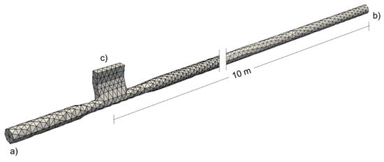
Figure 2.
Overall fluid mesh and the boundary regions: (a) air inlet, (b) outlet, and (c) seed inlet.

Table 2.
Computational fluid dynamic (CFD) solver boundary conditions for air velocity (ug), pressure (P), turbulent kinetic energy (k), and rate of dissipation of the turbulent kinetic energy (ε).
2.5. CFD-DEM Coupling
2.5.1. Navier–Stokes Equations
Under the CFD-DEM coupling approach, the Navier-Stokes equations for incompressible viscous flow are modified to include the effect of a particulate solid phase mixed into the fluid. The conservation of momentum is expressed as:
The conservation of mass is given by:
The particle fluid force accounting for surrounding particles is given by:
The drag coefficient is given by:
The particle Reynolds number is given by:
The voidage function exponent is given by:
where is the fluid density (kg/m3), α is the porosity, is the fluid velocity (m/s), t is time (s), p is the fluid pressure (Pa), µ is the fluid dynamic viscosity (kg/m.s), is the volume of the averaged body force (N/m3), Cd is the dimensionless drag coefficient, is the particle velocity (m/s), Rep is the particle Reynolds number, is the voidage function exponent, and is the acceleration due to gravity (m/s2).
Equations (10) and (11) show the modified Navier–Stokes equations for momentum and mass conservation, respectively. The formulation of the drag force (first term in Equation (12)) is accurate and smoothly varying for a wide range of porosities and Reynolds numbers. The second term in Equation (12) represents the particle buoyancy when the fluid pressure field contains a hydrostatic component. Equation (14) is applicable for higher Rep values typical of pneumatic conveyance. The voidage function exponent (Equation (15)) was empirically derived by Di Felice [36] for Rep values larger than 80. Porosity is calculated through a centroid method, which considers a particle to be entirely within a fluid element if its centroid is contained within that element. This method is fast, and it is conservative of the particle volume. However, this method can result in jumps in porosity as the particles move, which can reduce the smoothness of the solution. As the particle size decreases relative to the size of the fluid elements, this effect decreases. Hence, the requirement shown in Equation (6) is important to maintain the smoothness of the solution.
2.5.2. Timestep Considerations
Two-way coupling requires a series of data exchanges between OpenFOAM and PFC3D. Coupling interval, tc, is determined by the element size and air velocity. The following relationship is recommended to capture the coupling behavior [27]:
Seed velocity was not known at this point but was approximated to be less than the maximum air velocity based on the pneumatic conveying theory. Given the approximate element length of 2 × 10⁻² m and a maximum air inlet velocity of 25 m/s, the CFD-DEM coupling interval of 1 × 10⁻⁴ s was considered appropriate. Seed location information was transferred to the CFD solver during each CFD-DEM coupling interval to determine the porosity. The porosity was used by the CFD solver to calculate the updated air flow characteristics, and the air flow information was then sent back to the DEM solver to calculate the force applied to the seeds. The fluid solver timestep was assigned the same value as the coupling interval, and the DEM timestep was assigned a value of 1 × 10⁻⁶ s. This arrangement resulted in 100 DEM timesteps for each CFD timestep.
2.6. Simulation Parameters and Model Validation
Different combinations of the solid loading ratio (SLR) and air velocity were selected to understand the behaviors of the proposed CFD-DEM simulation. The selected seed rates and air velocities represent a wide range of agronomic practices for the practical use of air seeders. Slower air velocities are also included for validation purposes and to determine the effect of air velocity on the seed contact forces. The first set of simulations had a fixed SLR of 0.5 and air velocities of 10, 15, 20, and 25 m/s. The second set of simulations had varying SLR values: 0.5, 1.0, 1.5, 2.0, 2.5, and 3.0 and two different air velocities of 15 and 25 m/s. The simulation results for the average particle velocity were compared to a set of empirical equations developed by Santo et al. [37,38]. The equations are related to horizontal pneumatic conveying and describe the acceleration length and particle velocities as follows:
where La is the acceleration length (m), D is the pipe diameter (m), Ar is the Archimedes number, D50 is the internal pipe diameter with 50 mm (m), Reg is the gas Reynolds number, Up-ss is the particle steady-state velocity (m/s), Ug is the superficial air velocity (m/s), up is the particle velocity (m/s), and x is the distance from the seed feeding point (m). The correlations described in Equations (17)–(19) were originally developed for the following property ranges: 6 × 10⁻⁵ m < dp < 4 × 10⁻³ m, 940 kg/m3 < ρp < 5800 kg/m3, 14 m/s < ug < 28 m/s, 2.4 × 10⁴ < Reg < 1.41 × 10⁵, 2.6 × 10⁻² m < D < 7.6 × 10⁻² m, and 0.3 < SLR < 3.
In addition to particle velocities, the flow characteristics were compared to the current empirical models. Geldhart’s classification of fluidizing properties of granular materials is often used to determine the type of pneumatic conveying flow. The field peas used in the simulation are part of group D, which refers to free-flowing particles of large sizes and densities. The CFD-DEM simulation recorded the overall seed position through 10 m of horizontal conveying. This type of detailed data recording is one of the advantages of computer simulation techniques. Referring to the work of Kalman et al. [39] provides a means of comparison for the particle flow characteristics between the proposed simulation and current empirical models. Kalman et al. [39] described a three-zone model that correlates the Reynolds number and Archimedes number to the type of granular material flow regime. Granular materials that are part of group D, such as field peas, fall within Zone 1. The particle Reynold’s number that describes the boundary between the pickup and non-pickup regimes is defined for Zone 1 as:
where is the threshold particle Reynolds number for particle pickup.
Given that particle velocity data was readily available from our simulation, particle Reynolds numbers were calculated from Equation (10) and compared to the boundary region between pickup and non-pickup regimes for granular flow.
2.7. Data Analysis
A paired-samples t-test was conducted to evaluate the average seed velocity differences between the simulation and the empirical equations. The overall effect of other pneumatic-conveying conditions, such as SLR and air inlet velocity, on the seed average velocity and seed contact force were evaluated through a type III ANOVA. The software RStudio (RStudio, Inc., Boston, MA, USA) was used to analyze the data. Seed average velocity was calculated by recording the magnitude of individual seed velocities at 0.01-s intervals and taking the average as a function of seed location in the distributor tube. Contact force at each seed was recorded every 0.01 s and was extracted from the computation of contact force in the Hertz model. The contact force was computed as the sum of the Hertz force and the dashpot force at particle–particle and particle–wall interactions.
3. Results and Discussion
3.1. Seed Flow Characteristics and Model Validation
Average seed velocities at the end of the horizontal tube were recorded as 4.6, 6.8, 8.6, and 11.2 m/s at air velocities of 10, 15, 20, and 25 m/s, respectively. The simulation data shows that the seeds were still accelerating at the end of the horizontal tube. The rate of acceleration was higher closer to the seed feeding point as the seeds entered the conveying line. This was likely related to the geometry of the area around the feeding point and the overall difference between the air and seed velocity in this area. After the initial spike in seed acceleration, there was a steady acceleration decrease for the remaining length of the tubing. This coincided with the expectation that the seeds should accelerate at a slower rate as the differences in velocity between the air and the seed decreased. The proposed simulation method allowed the monitoring of all individual seed velocities and positions. Although the overall trend was that of seeds steadily accelerating, upon detailed inspection, it can be shown that the simulation method was able to capture changes in seed velocities due to collisions with the tubing, as well as other seeds. An example is presented in Figure 3, where the velocity profile of an individual seed is shown at different scales to highlight the changes in particle velocity.
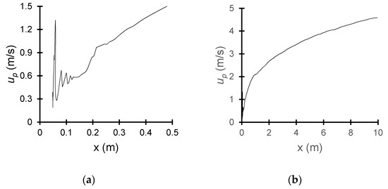
Figure 3.
Individual seed velocity (up) along the length of the distributor tube (x) at an air inlet velocity of 10 m/s and solids loading ratio of 0.5: (a) up shown at the first 0.5 m and (b) up shown at full simulated tube length.
A visual comparison of the average seed velocities as a function of the pipe length is shown in Figure 4. The figure compares the simulation results and the model proposed by Santo et al. [37,38]. The CFD-DEM simulation was able to capture the average behavior of the seeds well. However, there was a discrepancy in the initial average particle velocity, which was likely influenced by the change in tube diameter just below the seed inlet and its effect on the air velocity. The geometry had a slight diameter reduction in this area, which caused the seeds to accelerate faster during the first 0.5 m of tubing. This diameter reduction could not be included as part of the empirical model, which provided the most likely explanation for the source of the observed discrepancy. Figure 5 shows a sample air velocity profile across the area near the seed feeding point. After the first 0.5 m, there was a decrease in seed acceleration for the remaining length of the tubing. This was most noticeable at air velocities of 20 and 25 m/s. The average seed velocities were compared through a paired-samples t-test (α = 0.05), and the results were found to be not significantly different after the first 3 m of tubing. The seed flow behavior and average seed velocities were comparable to those observed in a CFD-DEM study by Kuang et al. [19].
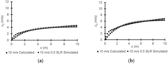
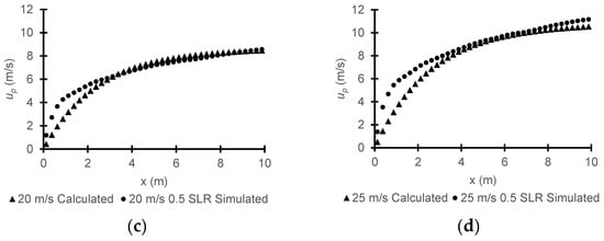
Figure 4.
Model validation results: calculated and simulated particle velocity (up) along the length of the distributor tube (x) for the air inlet velocities of (a) 10 m/s, (b) 15 m/s, (c) 20 m/s, and (d) 25 m/s. SLR: solid loading ratio.
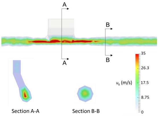
Figure 5.
Sample air velocity (ug) profile at the air inlet velocity of 25 m/s.
The simulation was qualitatively evaluated by examining the seed flow characteristics. Figure 6 shows an example of different SLR as the seeds flow between the seed inlet and the tube outlet. The air velocity value of 25 m/s is shown, because it represents the largest particle Reynold’s number and velocity combination observed during the simulations. Overall, seeds descended into the airflow and collided with each other, as well as adjacent walls. Seeds concentrated at the bottom of the tube wall within the first 0.5 m of flow and continued flowing mostly as a stratified smooth flow for the remaining tube length. The previously described seed flow was observed for all simulated air velocities. The largest average particle velocity and Reynold’s number were recorded at the end of the horizontal tube as 11.4 m/s and 6420, respectively. The simulation resulted in average particle velocities and Reynold’s numbers that were inside the boundaries of the non-pickup regime ( 6912). This confirmed the observed stratified smooth flow to be in agreement with the model proposed by Kalman et al. [39].
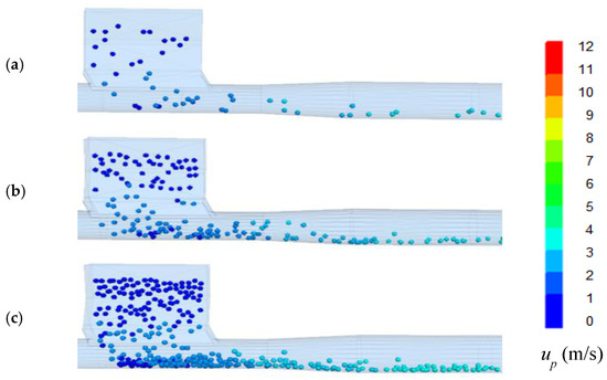
Figure 6.
Seed velocity (up) profile at the inlet air velocity of 25 m/s for solid loading ratios (SLRs) of (a) 0.5, (b) 1.5, and (c) 3.0.
3.2. Effect of the Solids Loading Ratio on the Average Particle Velocity
Comparison of the average particle velocity at different SLR showed that there was no significant difference (α = 0.05) between the average particle velocities at any given location of the tube. Figure 7 shows just how close the average particle velocities were between each SLR and air velocity combination. This type of comparison demonstrates an important feature of CFD-DEM simulations applied to air seeding systems that would not be available through other CFD methods for fluid–particle flow. Knowing that the average seed velocity will not be affected by the practical range of seeding rates of a given crop can assist equipment manufacturers during early design stages. Designers using CFD-DEM simulations would be able to perform modifications to air seeder distributor tube features (pipe transitions, tube diameter, and operating angle) to optimize the performance through virtual prototyping. Additionally, the simulation results provide an estimation that the model proposed by Santos et al. [37,38] is likely appropriate for the SLR commonly used in seeding and larger diameter particles like our simulated field pea seeds (d = 6.94 mm).
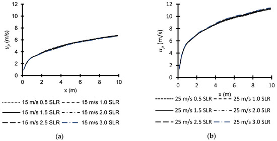
Figure 7.
Comparison of the simulated seed velocity (up) along the length of distributor tube (x) at multiple solids loading ratios (SLR) for air velocities of (a) 15 m/s and (b) 25 m/s.
3.3. Effect of Solids Loading Ratio on Seed Contact Force
Comparison of the average seed contact force showed that there was no significant difference (α = 0.05) between SLR ranging between 0.5 and 3.0 (Figure 8). However, there was a tube location effect, with seeds closest to the feeding point experiencing larger contact forces. This correlates well with the information extracted from the individual seed velocities (Figure 3), where small changes to the initial seed velocity patterns also indicated seed collisions close to the feeding point. Sudden changes in the seed flow direction from the combined effect of system geometry and air flow are likely responsible for the larger contact forces. The average contact force values remained relatively stable through the horizontal tube, with a few small peaks visible. Additional seed interaction details become noticeable if we consider all individual seed collisions at different SLR. This is demonstrated through Figure 9, which displays individual seed collisions at two different SLR (0.5 and 3.0) and a fixed air velocity (25 m/s). Seed contact forces that were above average represented 13% and 32% of all recorded contact forces for SLR of 0.5 and 3.0, respectively. Contact forces recorded within the first 2 m of tubing represented 90% of above-average contact forces for both SLR. This type of information can assist equipment designers in determining which percentage of the seeds are subjected to larger contact forces, as well as the specific location in the system. Larger contact forces are undesirable because of its correlation to the mechanical damage and its effect on the seed vigor and germination ability. A study by Guner [40] identified air velocity as a critical factor in seed mechanical damage during the pneumatic conveying of agricultural seeds. The use of a CFD-DEM simulation allowed us to incorporate the contact force as a performance indicator through the detailed examination of areas with a larger number of collisions. Although no contact model calibration was available to confirm the value of the contact force, we could still use the simulated average contact force as a tool to assess the seed feeding device or other high collision areas through benchmark simulations at various operating conditions.
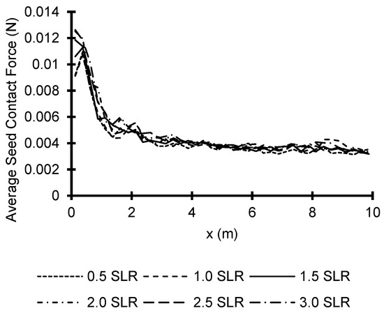
Figure 8.
Effects of the solids loading ratio (SLR) on the average seed contact force along the length of the distributor tube (x) at an air inlet velocity (ug) of 25 m/s.
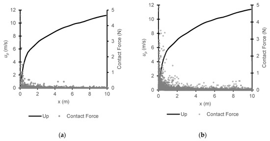
Figure 9.
Individual seed contact force along the length of the distributor tube (x) at an inlet air velocity (ug) of 25 m/s for solids loading ratios (SLR) of (a) 0.5 and (b) 3.0.
3.4. Effect of Air Velocity on Contact Force
The air velocity has been shown to have a significant effect on the average seed contact force (α = 0.05). The difference between each average contact force becomes more noticeable as the air velocity increases. The small peaks in the average contact force that were described in the previous section are also visible in Figure 10. The frequency and magnitude of these average contact force peaks increase as air velocity increases. The simulation results from Lei et al. [21] also suggested that the force applied to each seed is significantly affected by the air velocity. Additionally, the tube location effect that resulted from the feeding point geometry is extended at larger air velocities.
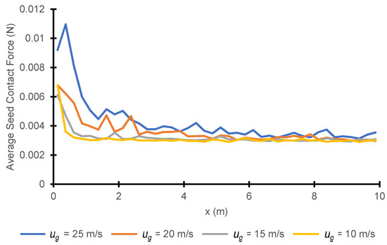
Figure 10.
Effect of air velocity (ug) on the average seed contact force.
4. Conclusions
This study focused on the CFD-DEM simulation on seed pneumatic conveying in an air seeder distributor tube. The CFD-DEM simulation was able to capture the average seed velocity, based on the validation results, and provide details about seed contact forces under various operating conditions. The different combinations of air velocities and SLR resulted in a stratified smooth seed flow at the bottom of the horizontal tube. The simulated seed velocity corresponded well with the empirical models for particle velocity and was not affected by the SLR values associated with practical seeding rates. Contact force monitoring was identified as a potential tool to minimize seed mechanical damage in the air seeding equipment, as well as other seed-handling applications. The average contact force values increased at larger air velocities, but this effect was mostly contained to the feeding point, where there was a larger number of seed collisions. The air velocity effect on the average contact force was still present through the 10 m of horizontal tubing but to a lesser extent.
These results will help us gain new insight and provide reliable methods for improving existing air seeding configurations. Future simulations with different operation conditions such as seed type, air velocities, and field conditions (i.e., seeding on a sloped vs. flat fields) could help farming operations make informed decisions that could improve their farming practices.
Author Contributions
Conceptualization, L.G. and Y.C.; methodology, L.G. and Y.C.; software, L.G.; formal analysis, L.G.; investigation, L.G.; writing—original draft preparation, L.G.; writing—review and editing, Y.C. and H.L.; and funding acquisition, Y.C. All authors have read and agreed to the published version of the manuscript.
Funding
This research was funded by The Natural Sciences and Engineering Research Council of Canada (NSERC), Grant No. RGPIN-2019-05861.
Conflicts of Interest
The authors declare no conflict of interest.
References
- Bucklin, R.; Thompson, S.; Abdel-Hadi, A.; Montross, M. Handbook of Farm Dairy and Food Machinery; Elsevier: San Diego, CA, USA, 2007; pp. 113–165. [Google Scholar]
- Mills, D. Pneumatic Conveying Design Guide, 2nd ed.; Elsevier: Amsterdam, The Netherlands; Butterworth-Heinemann: London, UK, 2004. [Google Scholar]
- Manjula, E.V.P.J.; Ariyaratne, W.K.H.; Ratnayake, C.; Melaaen, M.C. A review of CFD modelling studies on pneumatic conveying and challenges in modelling offshore drill cuttings transport. Powder Technol. 2017, 305, 782–793. [Google Scholar] [CrossRef]
- Baryeh, E.A. A simple grain impact damage assessment device for developing countries. J. Food Eng. 2003, 56, 37–42. [Google Scholar] [CrossRef]
- Ebrahimi, M.; Crapper, M.; Ooi, J.Y. Numerical and experimental study of horizontal pneumatic transportation of spherical and low-aspect-ratio cylindrical particles. Powder Technol. 2016, 293, 48–59. [Google Scholar] [CrossRef]
- Westerweel, J. Fundamentals of digital particle image velocimetry. Meas. Sci. Technol. 1997, 8, 1379–1392. [Google Scholar] [CrossRef]
- Yan, F.; Rinoshika, A. Application of high-speed PIV and image processing to measuring particle velocity and concentration in a horizontal pneumatic conveying with dune model. Powder Technol. 2011, 208, 158–165. [Google Scholar] [CrossRef]
- Ratnayake, C. A Comprehensive Scaling up Technique for Pneumatic Transport Systems. Ph.D. Thesis, Telemark University College, Porsgrunn, Norway, 2005. [Google Scholar]
- Chen, F. Coupled Flow Discrete Element Method Application in Granular Porous Media Using Open Source Codes. Ph.D. Thesis, University of Tennessee, Knoxville, TN, USA, 2009. [Google Scholar]
- Curtis, J.S.; van Wachem, B. Modeling particle-laden flows: A research outlook. AlChE J. 2004, 50, 2638–2645. [Google Scholar] [CrossRef]
- Gupta, P. Verification and Validation of a DEM-CFD Model and Multiscale Modelling of Cohesive Fluidization Regimes. Ph.D. Thesis, University of Edinburgh, Edinburgh, Scotland, 2014. [Google Scholar]
- Mezhericher, M.; Brosh, T.; Levy, A. Modeling of particle pneumatic conveying using DEM and DPM methods. Part. Sci. Technol. 2011, 29, 197–208. [Google Scholar] [CrossRef]
- Kruggel-Emden, H.; Oschmann, T. Numerical study of rope formation and dispersion of non-spherical particles during pneumatic conveying in a pipe bend. Powder Technol. 2014, 268, 219–236. [Google Scholar] [CrossRef]
- Brosh, T.; Kalman, H.; Levy, A.; Peyron, I.; Ricard, F. DEM–CFD simulation of particle comminution in jet-mill. Powder Technol. 2014, 257, 104–112. [Google Scholar] [CrossRef]
- Iqbal, N.; Rauh, C. Coupling of discrete element model (DEM) with computational fluid mechanics (CFD): A validation study. Appl. Math. Comput. 2016, 277, 154–163. [Google Scholar] [CrossRef]
- Liu, M.; Wen, Y.; Liu, R.; Liu, B.; Shao, Y. Investigation of fluidization behavior of high density particle in spouted bed using CFD-DEM coupling method. Powder Technol. 2015, 280, 72–82. [Google Scholar] [CrossRef]
- Yang, S.; Luo, K.; Zhang, K.; Qiu, K.; Fan, J. Numerical study of a lab-scale double slot-rectangular spouted bed with the parallel CFD-DEM coupling approach. Powder Technol. 2015, 272, 85–99. [Google Scholar] [CrossRef]
- Kuang, S.B.; Yu, A.B. Micromechanic modeling and analysis of the flow regimes in horizontal pneumatic conveying. AlChE J. 2011, 57, 2708–2725. [Google Scholar] [CrossRef]
- Kuang, S.; Li, K.; Yu, A. CFD-DEM Simulation of Large-Scale Dilute-Phase Pneumatic Conveying System. Ind. Eng. Chem. Res. 2020, 59, 4150–4160. [Google Scholar] [CrossRef]
- Bayati, M.; Johnston, C. CFD-DEM Investigation of Seed Clustering in an Air Seeder with the Immersed Boundary Method; Radix Innovation Corporation: Calgary, AB, Canada, 2017. [Google Scholar]
- Lei, X.; Liao, Y.; Liao, Q. Simulation of seed motion in seed feeding device with DEM-CFD coupling approach for rapeseed and wheat. Comput. Electron. Agric. 2016, 131, 29–39. [Google Scholar] [CrossRef]
- Lei, X.; Liao, Y.; Zhang, Q.; Wang, L.; Liao, Q. Numerical simulation of seed motion characteristics of distribution head for rapeseed and wheat. Comput. Electron. Agric. 2018, 150, 98–109. [Google Scholar] [CrossRef]
- Wojtkowski, M.; Pecen, J.; Horabik, J.; Molenda, M. Rapeseed impact against a flat surface: Physical testing and DEM simulation with two contact models. Powder Technol. 2010, 198, 61–68. [Google Scholar] [CrossRef]
- Woo, M.W.; Daud, W.R.W.; Mujumdar, A.S.; Tasirin, S.M.; Talib, M.Z.M. Role of rheological characteristics in amorphous food particle-wall collisions in spray drying. Powder Technol. 2010, 198, 251–257. [Google Scholar] [CrossRef]
- He, Y.; Bayly, A.E.; Hassanpour, A. Coupling CFD-DEM with dynamic meshing: A new approach for fluid-structure interaction in particle-fluid flows. Powder Technol. 2018, 325, 620–631. [Google Scholar] [CrossRef]
- Zhan, Z.; Yaoming, L.; Zhenwei, L.; Zhiqiang, G. DEM simulation and physical testing of rice seed impact against a grain loss sensor. Biosyst. Eng. 2013, 116, 410–419. [Google Scholar] [CrossRef]
- Itasca. PFC3D Particle Flow Code in 3 Dimensions, Verification Problems and Example Applications; Itasca Consulting Group, Inc.: Minneapolis, MN, USA, 2017. [Google Scholar]
- Wiacek, J.; Molenda, M.; Horabik, J.; Ooi, J.Y. Influence of grain shape and intergranular friction on material behavior in uniaxial compression: Experimental and DEM modeling. Powder Technol. 2012, 217, 435–442. [Google Scholar] [CrossRef]
- Johaness, D.N. The Effectiveness of Particle Dampers Under Centrifugal Loads. Ph.D. Thesis, University of Stellenbosch, Stellenbosch, South Africa, 2009. [Google Scholar]
- Guzman, L.J.; Chen, Y.; Landry, H. Discrete element modeling of seed metering as affected by roller speed and damping coefficient. Trans. ASABE 2020, 63, 189–198. [Google Scholar] [CrossRef]
- Balevičius, R.; Sielamowicz, I.; Mróz, Z.; Kačianauskas, R. Investigation of wall stress and outflow rate in a flat-bottomed bin: A comparison of the DEM model results with the experimental measurements. Powder Technol. 2011, 214, 322–336. [Google Scholar] [CrossRef]
- Horabik, J.; Molenda, M. Parameters and contact models for DEM simulations of agricultural granular materials: A review. Biosyst. Eng. 2016, 147, 206–225. [Google Scholar] [CrossRef]
- Tsuji, Y.; Kawaguchi, T.; Tanata, T. Discrete Particle Simulation of Two-Dimensional Fluidized Bed. Powder Technol. 1993, 77, 79–87. [Google Scholar] [CrossRef]
- Shimizu, H.; Murata, S.; Ishida, T. The distinct element analysis for hydraulic fracturing in hard rock considering fluid viscosity and particle size distribution. Int. J. Rock Mech. Min. Sci. 2011, 48, 712–727. [Google Scholar] [CrossRef]
- Kalitzin, G.; Medic, G.; Iaccarino, G.; Durbin, P. Near-wall behavior of RANS turbulence models and implications for wall functions. J. Comput. Phys. 2005, 204, 265–291. [Google Scholar] [CrossRef]
- Di Felice, R. The voidage function for fluid-particle interaction systems. Int. J. Multiph. Flow 1994, 20, 153–159. [Google Scholar] [CrossRef]
- Santo, N.; Portnikov, D.; Tripathi, N.M.; Kalman, H. Experimental study on the particle velocity development profile and acceleration length in horizontal dilute phase pneumatic conveying systems. Powder Technol. 2018, 339, 368–376. [Google Scholar] [CrossRef]
- Santo, N.; Portnikov, D.; Eshel, I.; Taranto, R.; Kalman, H. Experimental study on particle steady state velocity distribution in horizontal dilute phase pneumatic conveying. Chem. Eng. Sci. 2018, 187, 354–366. [Google Scholar] [CrossRef]
- Kalman, H.; Satran, A.; Meir, D.; Rabinovich, E. Pickup (critical) velocity of particles. Powder Technol. 2005, 160, 103–113. [Google Scholar] [CrossRef]
- Güner, M. Pneumatic conveying characteristics of some agricultural seeds. J. Food Eng. 2007, 80, 904–913. [Google Scholar] [CrossRef]
Publisher’s Note: MDPI stays neutral with regard to jurisdictional claims in published maps and institutional affiliations. |
© 2020 by the authors. Licensee MDPI, Basel, Switzerland. This article is an open access article distributed under the terms and conditions of the Creative Commons Attribution (CC BY) license (http://creativecommons.org/licenses/by/4.0/).