Article

Study on Two Types of Stall Patterns in a Centrifugal Compressor with a Wide Vaneless Diffuser

School of Energy, Power & Mechanical Engineering, North China Electric Power University, Baoding 071028, China
*
Author to whom correspondence should be addressed.
Processes 2020, 8(10), 1251; https://doi.org/10.3390/pr8101251
Submission received: 8 September 2020 / Revised: 27 September 2020 / Accepted: 29 September 2020 / Published: 4 October 2020
(This article belongs to the Section Advanced Digital and Other Processes)

Abstract

:
Two types of stall patterns in the centrifugal compressor with a wide vaneless diffuser were numerically studied in this paper. We carried out kinds of three-dimensional numerical simulations of the instability process in wide vaneless diffusers with different radius ratios. The results show that there are two kinds of stall patterns in wide vaneless diffusers with different radius ratios. For a short diffuser with a radius ratio of 1.5, the speed of the propagation of stalled cells is relatively high, and the propagation speed and frequency of stall cells do not change with the decrease in the flow rate. For a long diffuser with a radius ratio of 1.8, the propagation velocity of stall cells is smaller to the one in the short diffuser, and increases with the decrease in flow rate. For wide vaneless diffusers with different radius ratios, the main factor causing stall is the outlet reflux. Reducing the radius ratio of the wide vaneless diffuser has an important influence on the stability of the centrifugal compressor.

1. Introduction

Centrifugal compressors are widely used in the national economy because of their simple structure and high single-stage pressure ratio. However, instability has plagued the safe and stable operation of small flow compressors, such as rotating stalls and surges. When a rotating stall occurs, the performance of a centrifugal compressor will drop sharply, and the blades will be damaged due to the alternating stress [1,2,3]. Rotating stall can occur in the diffuser and impeller [4]. When rotating stall occurs in a diffuser, the compressor will be more damaged due to the larger reverse pressure gradient in the diffuser [5]. Therefore, studying the rotating stall law and mechanism of the diffuser is of great significance to the design and stable operation of the centrifugal compressor.
The hydrodynamic mechanism of rotating stall in a diffuser has always been a hot research topic in the past. Jansen [6] predicted the instability of the vaneless diffuser by establishing a theoretical model, and the prediction results show that the instability of the centrifugal compressor is mainly related to the radial reflux of the boundary layer. Senoo and Kinoshita et al. [7,8] studied the rotating stall of different diffusers through experiments, and found that rotating stall only occurs when the reflux area is generated and developed to a certain extent. They also found that the smaller the critical flow angle, the greater the stability margin of the diffuser. Abdelhamid and Tsujimoto et al. [9,10] used two-dimensional inviscid and incompressible flow theory to analyze the rotating stall of a vaneless diffuser under the premise of ignoring the boundary layer. The results showed that the unsteady two-dimensional core flow was related to the rotating stall. However, in the vaneless diffuser there is a complex three-dimensional unsteady flow, and the three-dimensional factors that cause the rotating stall cannot be detected using a two-dimensional model. Dou et al. [11] studied the rotating stall of a vaneless diffuser using three-dimensional boundary layer theory. The results showed that the three-dimensional distorted boundary layer has an important influence on causing rotating stall. Ljevar and Shin et al. [12,13] unified the above-mentioned points. They considered that the mechanisms of rotating stall between wide and narrow diffusers might be different. The rotating stall induction of a narrow diffuser is related to the instability of the three-dimensional boundary layer, while that of a wide diffuser is related to the instability of the two-dimensional core flow.
Based on the above studies, we can find that the geometric parameters of diffuser have an important influence on the inducement of rotating stall. Abdelhamid et al. [14] studied various vaneless diffusers with different aspect ratios and radius ratios through experiments. It was found that there were two different disturbance frequencies for vaneless diffusers with the same width–diameter ratio and radius ratio, and with the decrease in flow rate the circumferential propagation speed was different. Then, Abdelhamid and Dazin et al. [15,16] studied the rotating stall of wide-bladed diffusers with different radius ratios. The results showed that there were three rotating stall zones in the large radius ratio vaneless diffuser at different flow rates—i.e., a low-speed propagation zone, transition zone, and high-speed propagation zone. The propagation speed of a rotating stall cell was relatively small in the inducement stage, the stall cell number and the propagation speed change with time in the transition zone, and the propagation speed of the stall cell increases when the flow rate is smaller. However, there is no evolutionary process of the propagation velocity from low to high in smaller radii than the vaneless diffuser. Based on this, Abdelhamid believed that there were two different stall patterns in vaneless diffusers. Chu et al. [17] also found a similar phenomenon in their experiment. There were two kinds of rotating stall phenomena with different frequencies, and the number of stall cells was also changed. Shen et al. [18] studied that influence of diffuser geometric parameters on rotating stall, and also indicated that there might be different stall-inducing mechanisms in long and short vaneless diffusers. They believed that the critical stall flow of long diffusers was greatly affected by the inlet mach number, while that of short diffusers was greatly affected by the inlet axial flow velocity. Halawa et al. [19,20] calculated the rotating stall phenomenon of the vaned diffuser of the centrifugal compressor. It was found that the vaneless area between the impeller and the diffuser near the shroud side resulted in an insufficient radial velocity of the impeller, which led to the formation of stall cells. Zhu et al. [21] researched the internal flow field of different-width vaneless diffusers under stall conditions. The results show that the wave generation area is mainly located on the center line of the intersection of the narrow-diffuser boundary layer. The stall wave was mainly generated near the center line of the boundary layer intersection of the diffuser with a medium width.
Research on the rotating stall of vaneless diffusers has made a lot of advancements. Ötügen et al. [22] studied the unsteady flow and rotating stall of a vaneless diffuser. The result revealed that the stall onset will be delayed with the reduction in width of the vaneless diffuser, and the number of stall cells was also changed with the width of the vaneless diffuser and the mass flow rate; Filip et al. [23] has also proved this point. Ötügen believed that rotating stall was associated with the reverse flow region on the hub side. Zhang et al. [24] wrote a review of rotating stall in the vaneless diffuser with a centrifugal compressor. They summarized the research on rotating stall in recent decades. Hu et al. [25] established a mathematical model to predict the rotating stall and, though this model, he found that the active application of initial conditions in the upstream of the boundary layer on the diffuser walls can effectively control the downstream flow. However, it is a pity that there have not been any studies on the similarities and differences between the two types of stall patterns and the mechanisms of stall inducement in wide vaneless diffusers since Abdelhamid made this point.
In this paper, a numerical simulation of the rotating stall in a wide vaneless diffuser is carried out. The relationship between the number of stall holes, the propagation velocity, and the stall frequency in wide-leaf vaneless diffusers with different radius ratios is analyzed. Two kinds of stall patterns are explored in the wide vaneless diffuser. The differences in the stall inducement mechanism of wide vaneless diffusers with different radius ratios are revealed.

2. Computing Method

2.1. Geometry Model

The geometry model of the centrifugal impeller was designed by the Vista CCD of the ANSYS software package platform. The number of main blades and splitter blades was 6. The designed impeller model was inputted into Bladegen and further optimized. The geometric models of the impeller and diffuser are shown in Figure 1. Table 1 shows the main geometric parameters of the centrifugal compressor. Diffuser 1 and 2 represent wide vaneless diffusers with radius ratios of 1.8 and 1.5, respectively; the chosen radius ratio covers two kinds of diffusers—i.e., long and short. The elative outlet width of the impeller b2/r2 = 0.1633. b2 and r2 represent the outlet width and outlet radius of the impeller, respectively. r3 and r4 represent the inlet radius and outlet radius of the diffuser, respectively.

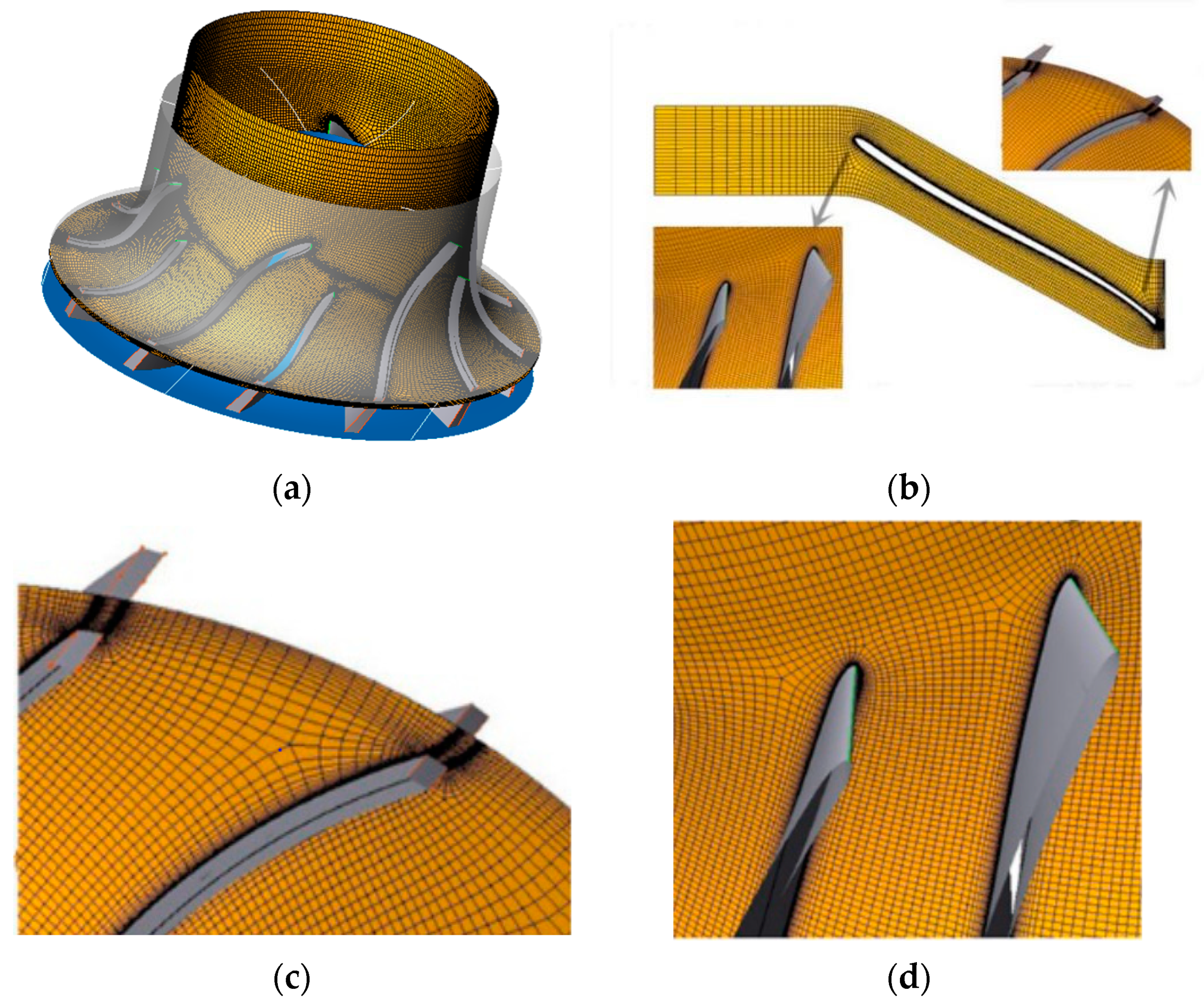
2.2. Mesh Generation

In this paper, the centrifugal impeller was meshed on Turbogrid of the Ansys 18.0 platform (The ANSYS company, Pittsburgh, PA, USA.) by automatic grid generation technology. The standard hexahedral structured mesh was generated by Gambit 6.2.3. to mesh the vaneless diffuser walls. The topology set was used to generate H-type mesh for impeller channels and O-type mesh for the area near the blade walls. The grids of a single channel are shown in Figure 2. Considering the influence of the boundary layer, the wall function was set on the shroud and hub of the vaneless diffuser. The number of cells in the boundary layer is 15, and the growth rate is 1.2. The y + of the wall is about 1.
In order to eliminate the influence of the grid number on the accuracy and calculation time, the grid independence verification of a vaneless diffuser with a radius ratio of 1.8 was conducted. As shown in Figure 3, five grid numbers were chosen to conduct calculations; the grid numbers were 4.02 million, 4.65 million, 5.23 million, 5.89 million, and 6.48 million, respectively. Isentropic efficiency is the ratio of the isentropic power of the compressor to the actual power required by the compressor. According to the isentropic efficiency under the design conditions, when the grid number reached 5.23 million, the isentropic efficiency hardly changed. Therefore, the total grid number of 5.23 million was selected to conduct future calculations, including 3.51 million grids for the centrifugal impeller and 1.72 million grids for the vaneless diffuser.

2.3. Governing Equations and Boundary Conditions

This paper focuses on the unsteady flow in the vaneless diffuser; the SST k-ω [26,27] turbulence model was selected to solve the three-dimensional Reynolds time-averaged N-S equation. This turbulence model considered the propagation of turbulent shear force; had a high-precision calculation ability for the boundary layer region; and had a good performance for the boundary layer flow of the inverse pressure gradient, the flow separation, and the secondary flow. The convection term adopted the high-precision discrete scheme of CFX software. The turbulent term adopted the adaptive central-bounded numerical scheme, which made the discrete scheme as close to the second order as possible.
In this paper, the fluid was dry air at 20 °C and full passage simulation was conducted. The centrifugal impeller was set as the rotor and the vaneless diffuser was set as the stator. The interface was the frozen rotor type, the shroud and hub of the compressor were insulated, and there were no slip walls. In the steady calculation, the impeller inlet adopted the uniform inflow condition. The total pressure at the inlet was 101,325 Pa, the total temperature was 293.15 K, the air flow direction angle was axial, and the outlet of the vaneless diffuser was set as the flow outlet. In the unsteady calculation, we take the steady calculation results as the initial unsteady field under critical stall condition to obtain the unsteady convergence solutions. We set the inlet boundary as the flow inlet and the outlet to be the opening boundary condition with a given static pressure. Under this condition, the reflux was allowed at the outlet. Taking the unsteady convergent results as the initial field, we adjusted the outlet back pressure of the vaneless diffuser gradually until the compressor entered the stall condition.
In steady calculations, when the maximum residual decreased three orders of magnitude or above, the inlet and outlet flow rate remained stable and the difference was less than 1%, and the compressor efficiency remained stable, the steady calculation was considered convergence. The convergence flow rate condition was defined as the critical stall condition. In unsteady calculations, the impeller was set with 240 time steps per cycle. The maximum internal iteration steps was 30, and the time step was 0.000056 s.
In order to verify the accuracy of the computing method adopted in this paper, the data of Krain’s impeller [28] published by ANSYS were selected for numerical calculation. As shown in Figure 4, comparing the simulation results with those of other researchers and the experimental results published in the literature, it was found that the overall error between the simulation and the experimental results was less than 5%, which verified the accuracy of the calculation model used in this paper.

3. Analysis and Results

3.1. Stall Pattern of Vaneless Diffuser with Large Radius Ratio in Centrifugal Compressor

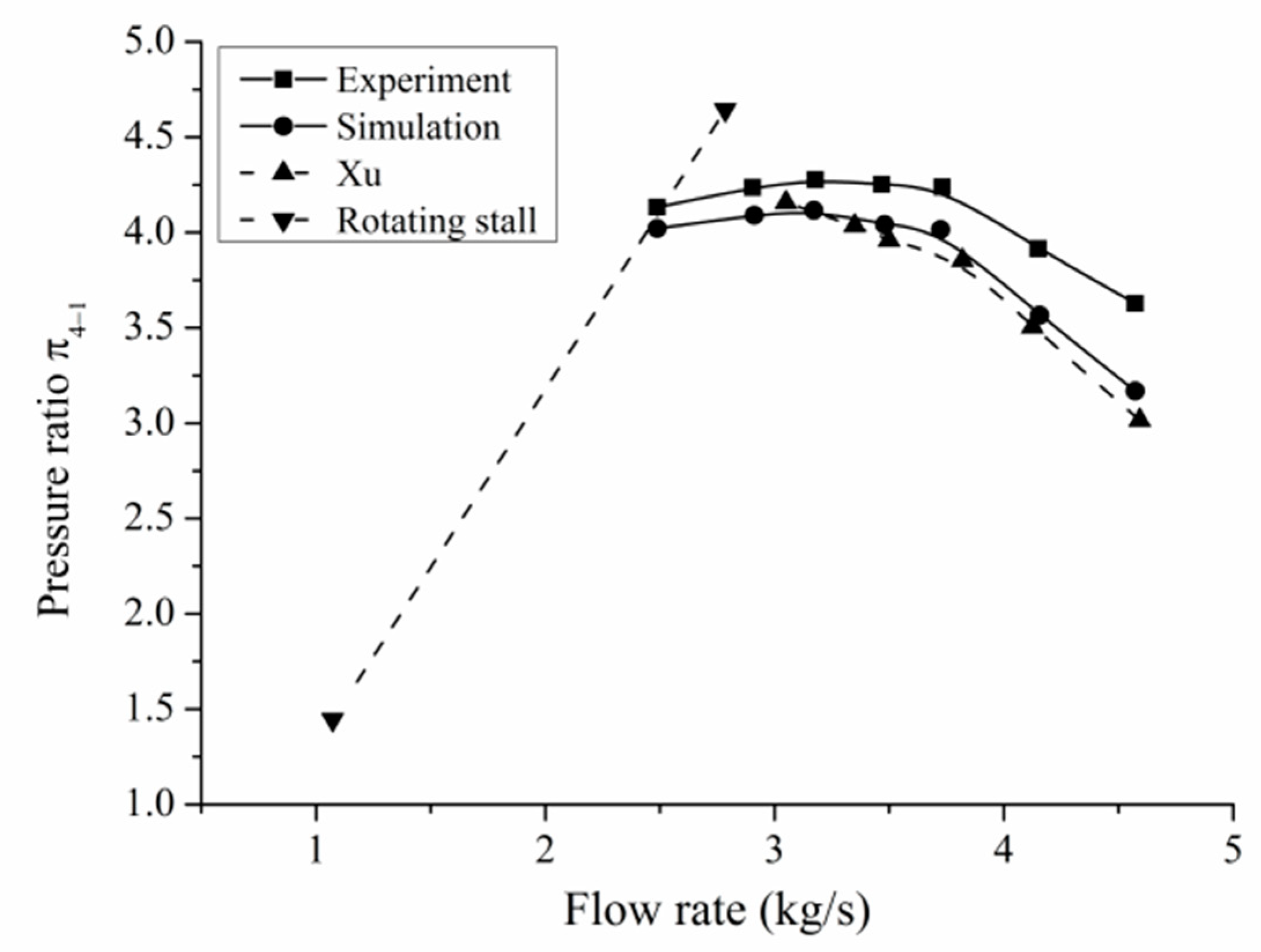
3.1.1. Analysis of Compressor Performance

The compressor performance curve of the flow rate and pressure ratio is shown in Figure 5. As shown in Figure 5, the total pressure ratio increases with the decrease in the flow rate. When the flow rate decreases to 1.15 kg/s, the total pressure ratio of the compressor reaches the maximum value. When the flow rate decreases to 1.1 kg/s, unsteady flow occurs in the compressor, with increased flow losses and a declined pressure ratio. When the centrifugal compressor continues to operate at a smaller flow rate, the compressor pressure ratio continues to decline. When the flow rate is 1.15 kg/s, the near-rotating stall condition of the centrifugal compressor is achieved.

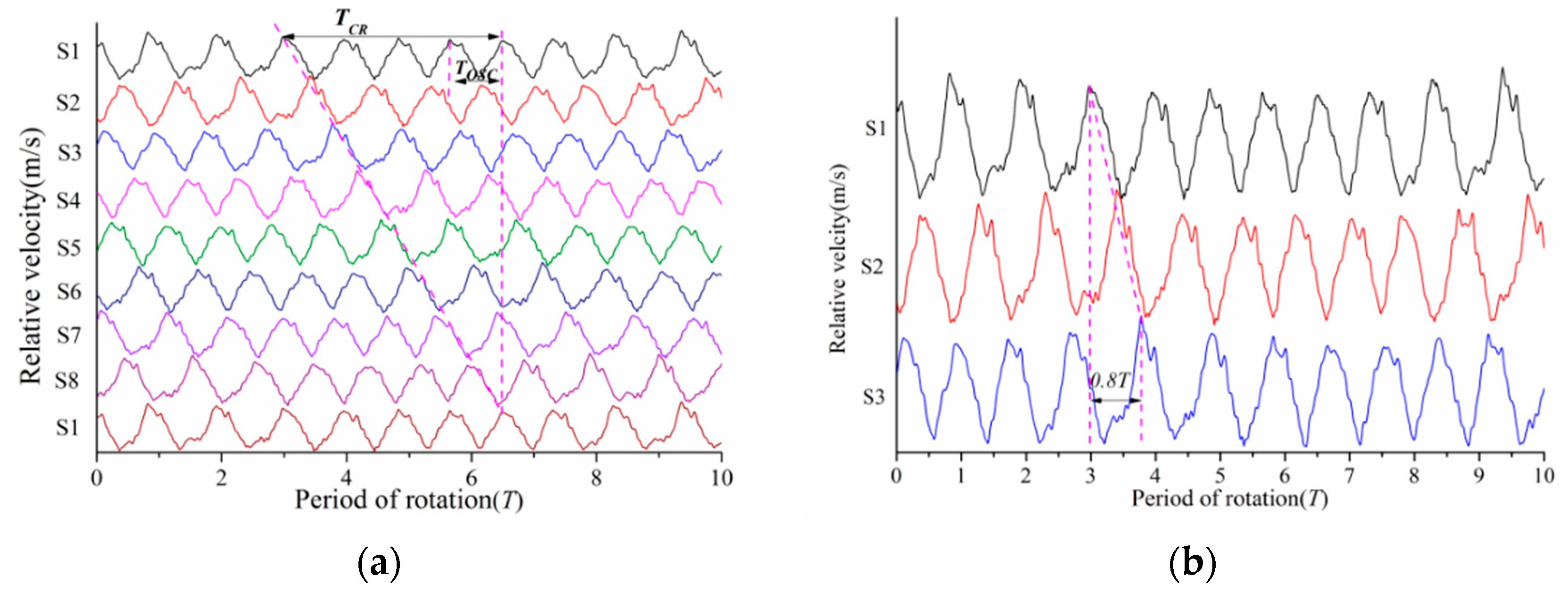
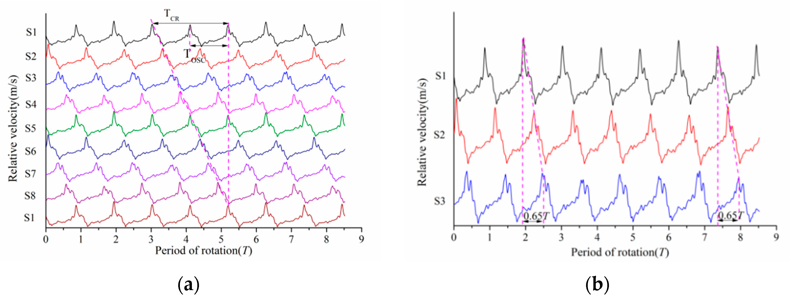
3.1.2. The Number and Propagation Speed of Stall Cells

In order to monitor the change in the internal relative velocity in the vaneless diffuser, eight numerical probes, labeled S1–S8, were evenly arranged in a 50% span middle section of the vaneless diffuser. The numerical probe positions are shown in Figure 6.
The number of stall clusters is determined by the formula: n = TCR/TOSC. The TCR represents the propagation period of stall cells measured at each monitoring point, and the TOSC represents the propagation period of stall cells measured at a single monitoring point. As shown in Figure 7a, each monitoring point shows a stable periodic fluctuation after about 8 rotor cycles, when the stable stall cell is formed. In the stage of stable development of the stall cell, TCR/TOSC = 4, it is determined that the number of stable stall cells in the vaneless diffuser is four.
In order to analyze the stall inception and the propagation speed of the stall cell, the velocity curves at three adjacent monitoring points were analyzed. As shown in Figure 7b, the phase difference of the stall inception measured at S1 and S3 is about 1.5 T. According to the formula of the stall inception propagation speed, the propagation speed is about 16% of the impeller speed.
The formula of the stall inception circumferential propagation speed is as follows:
ω s = P m P s ω r = 90 ° 1.5 * 360 ° ω r = 0.16 ω r
According to Figure 7b, the phase difference of the stall cell measured at S1 and S3 is about 0.9 T. According to the formula of the stall cell propagation speed, the stall cell propagation speed is 27.8% of the impeller speed.
The formula of the stall cell circumferential propagation speed is as follows:
ω T = P m P T ω r = 90 ° 0.9 * 360 ° ω r = 0.278 ω r
where Pm, Ps, and PT represent the phase difference between the monitoring points, the stall inception, and the stall cell, respectively. ω r represents the rotation speed of the impeller, and the unit is rmp/min. ω s represents the circumferential propagation speed of the stall inception, and the unit is rmp/min. ω T represents the circumferential propagation speed of the stable stall cell, and the unit is rmp/min. Unless otherwise specified, the following propagation speed unit is rmp/min.
In order to investigate the characteristics of the stall cell in a diffuser under different stall flow rate conditions, a further reduction in flow rate is needed. As shown in Figure 8a, when the flow rate is 1.0 kg/s, TCR/TOSC = 4, the number of stable stall cells in the vaneless diffuser is 4. At this time, the number of stall cells has not been changed.
As shown in Figure 8b, the phase difference of stall cell measured at S1 and S3 is 0.87 T. According to the formula of the stall cell propagation speed, the propagation speed of the stall cell is 28.4% of the impeller speed.
The formula of the stall cell circumferential propagation speed is as follows:
ω T = P m P T ω r = 90 ° 0.87 * 360 ° ω r = 0.284 ω r
When the flow rate is reduced to 0.9 kg/s, the relative speed curve of the monitoring point in the 50% span middle section of the diffuser is shown in Figure 8. As shown in Figure 9a, it can be seen that TCR/TOSC = 4; the number of stall cells is not changed.
As shown in Figure 9b, the phase difference of the stall cell measured at S1 and S3 is 0.85 T. According to the formula of the stall cell propagation speed, the propagation speed of the stall cell is 29.4% of the impeller speed.
The formula of the stall cell circumferential propagation speed is as follows:
ω T = P m P T ω r = 90 ° 0.85 * 360 ° ω r = 0.294 ω r
When the flow rate is reduced to 0.8 kg/s, the relative speed curve of the monitoring point in the 50% span middle section of the diffuser is shown in Figure 9. According to Figure 10a, TCR/TOSC = 4; the number of stable stall cells is 4.
As shown in Figure 10b, the phase difference of the stall cell measured at S1 and S3 is 0.8 T. According to the calculation formula of the stall cell propagation speed, the propagation speed of the stall cell is 31.3% of the impeller speed.
The calculation formula of the stall cell circumferential propagation speed is as follows:
ω T = P m P T ω r = 90 ° 0.8 * 360 ° ω r = 0.313 ω r
When the flow rate is reduced to 0.6 kg/s, the speed curve of the monitoring point in the 50% span intermediate section of the diffuser is shown in Figure 10. According to Figure 11a, TCR/TOSC = 4; the number of stable stall cells in the vaneless diffuser is 4.
As shown in Figure 11b, the phase difference of the stall cell measured at S1 and S3 is 0.8 T. According to the formula of the stall cell propagation speed, the propagation speed of the stall cell is 31.3% of the impeller speed.
The formula of the stall cell circumferential propagation speed is as follows:
ω T = P m P T ω r = 90 ° 0.8 * 360 ° ω r = 0.313 ω r

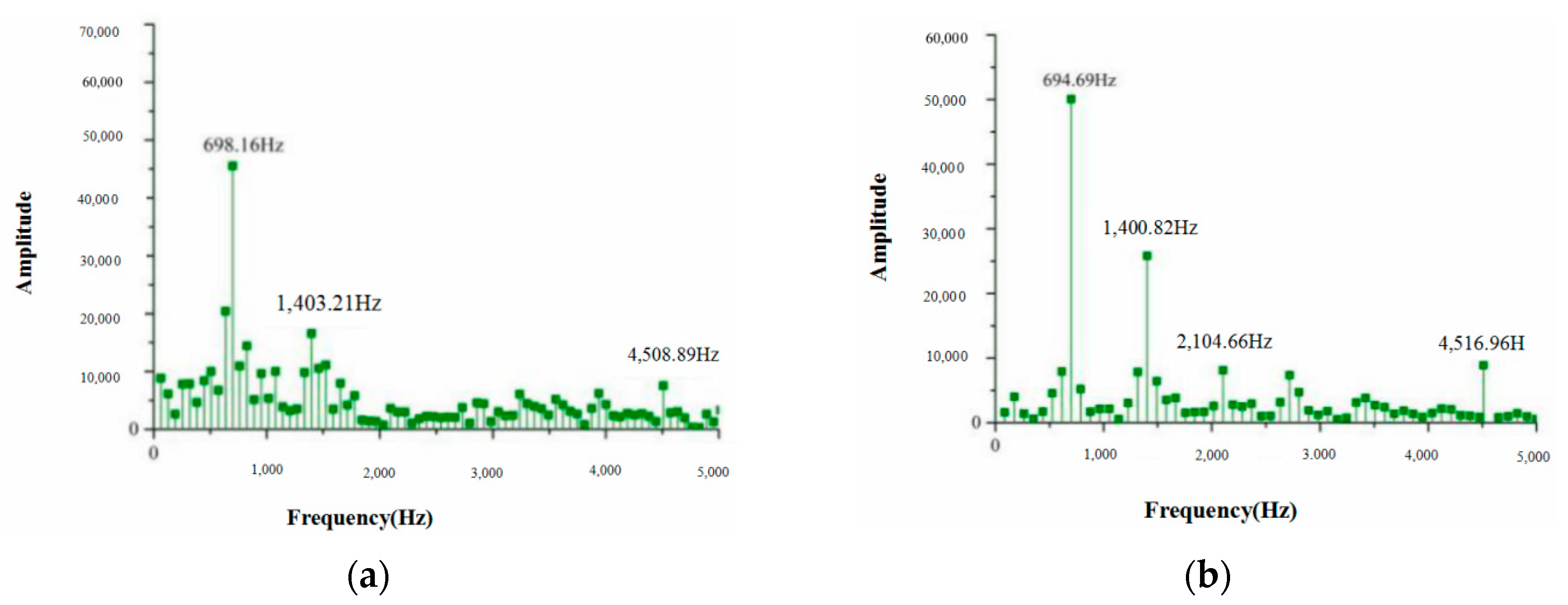
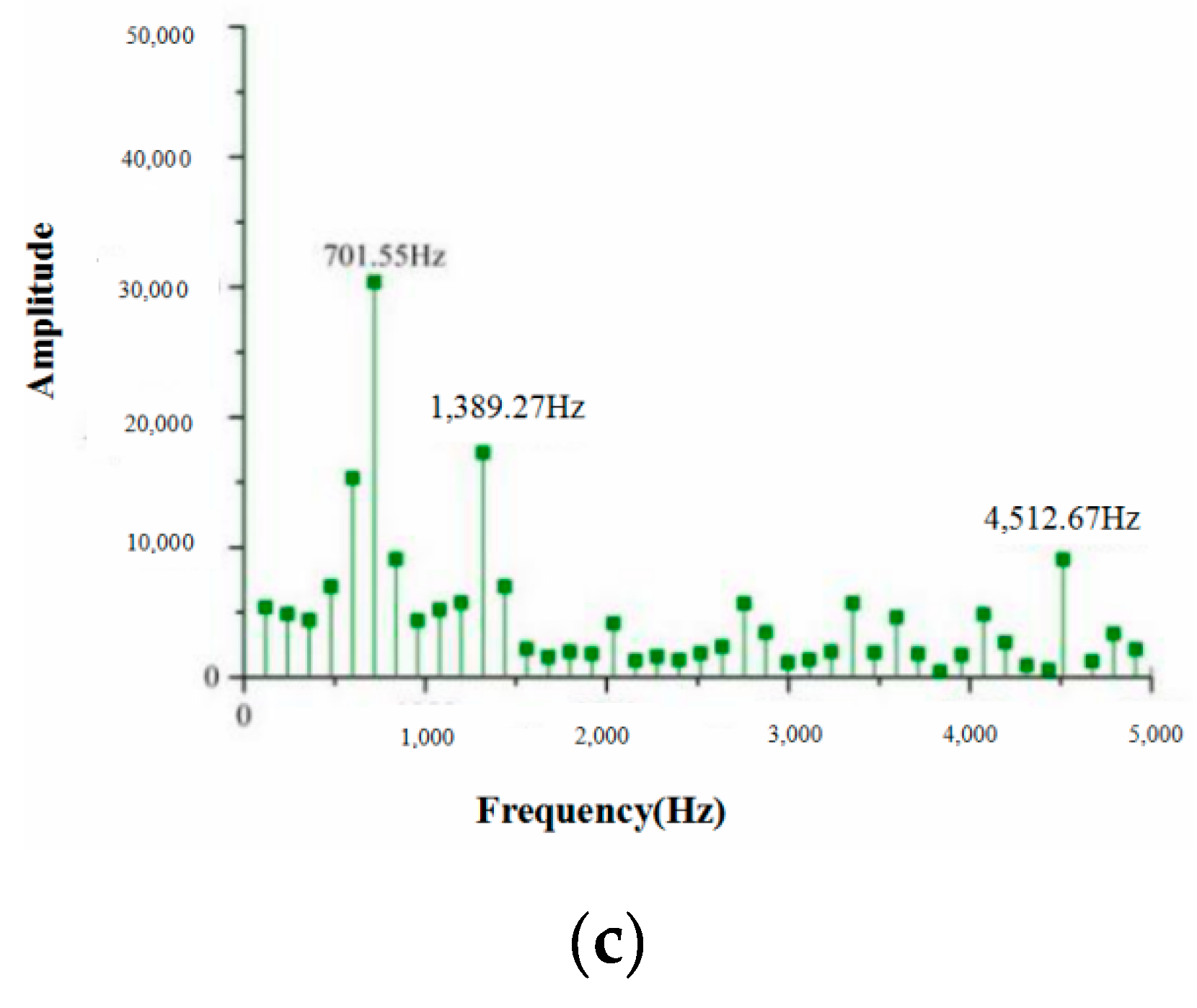
3.1.3. Analysis of Stall Frequency Characteristics

Take the relative speed curve of S1 as an example; fast Fourier transform (FFT) on the speed of S1 under the stall flow rate condition is carried out, and the frequency domain characteristic curve is obtained. This is shown in Figure 12a, which shows the spectrum analysis of the relative speed at S1 when the flow rate is reduced to 1.1 kg/s. There are isolated discrete frequency waves in the high-frequency band and the low-frequency band, with the frequency of 749.99 Hz and 4499.99 Hz, respectively. According to the frequency formula, the passing frequency of the blades is 4500 Hz. Therefore, 4499.99 Hz is the blade passing frequency, and the stall frequency is 749.99 Hz. Similarly, as shown in Figure 12b, when the flow rate is reduced to 0.9 kg/s, the stall frequency is 827.24 Hz. Figure 12c shows the spectrum distribution of the relative speed under the flow rate of 0.6 kg/s, and the stall frequency under this condition is 900.23 Hz.

3.2. Stall Pattern of Vaneless Diffuser with Small Radius Ratio in Centrifugal Compressor

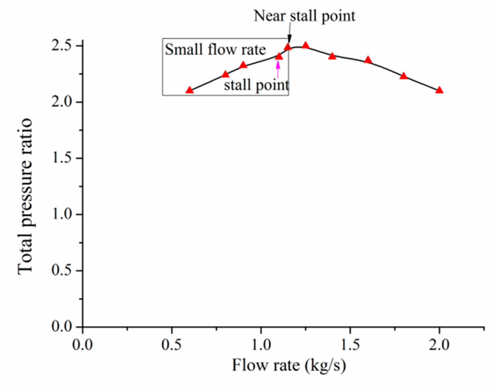
3.2.1. Analysis of Compressor Performance

The flow rate and pressure ratio characteristic curve of the centrifugal compressor is shown in Figure 13. The total pressure ratio increases with the decrease in the flow rate. When the flow rate decreases to 1.05 kg/s, the compressor pressure ratio reaches the maximum value. When the flow rate continues to decrease to 1.0 kg/s, unsteady flow occurs in the centrifugal compressor, with the flow losses increased and the pressure ratio declined, and the performance curve skew rate is negative. When the flow rate continues to decrease, the compressor pressure ratio continues to decline. The value of 1.05 kg/s is the near-stall flow rate condition of the centrifugal compressor.
Figure 14 shows the relative velocity curve of the internal monitoring points of the vaneless diffuser when the flow rate is 1.0 kg/s. It can be seen that the relative speed curve at each monitoring point forms an obvious periodic fluctuation after about 8 rotor cycles; the stable stall cell forms and continues to keep stable in the subsequent evolution cycle. When the stall cells develop stably, TCR/TOSC = 2, the number of stable stall cells in the vaneless diffuser is 2.
According to Figure 14a, the phase difference in the stall inception measured at S1 and S3 is about 1.0 T. According to the formula of the stall inception propagation speed, the propagation speed of stall inception is about 25% of the impeller speed.
The formula of the stall inception circumferential propagation velocity is as follows:
ω s = P m P s ω r = 90 ° 1.0 * 360 ° ω r = 0.25 ω r
As shown in Figure 14b, the phase difference of the stall cell measured at S1 and S3 is 0.65 T. According to the formula of the stall cell propagation speed, the circumferential propagation speed of the stall cell is about 38% of the impeller speed.
The formula of the stall cell circumferential propagation speed is as follows:
ω T = P m P T ω r = 90 ° 0.65 * 360 ° ω r = 0.38 ω r
When the flow rate reduced to 0.8 kg/s, the relative speed curve of the monitoring point in the 50% span middle section of the diffuser is shown in Figure 15a. In the figure, TCR/TOSC = 2. The number of stall cells is not changed.
As shown in Figure 15b, the phase difference of the stall cell measured at S1 and S3 is 0.65 T. According to the formula of the stall cell propagation speed, the propagation speed of the stall cell is 38% of the impeller speed.
The formula of the stall cell circumferential propagation speed is as follows:
ω T = P m P T ω r = 90 ° 0.65 * 360 ° ω r = 0.38 ω r .
When the flow rate reduced to 0.7 kg/s, the relative speed curve of the monitoring point in the 50% span intermediate section of the diffuser is shown in Figure 16a. It can be seen from the figure that TCR/TOSC = 2; the number of stable stall cells is 2.
As shown in Figure 16b, the phase difference of the stall cell measured at S1 and S3 is 0.65 T. According to the formula of the stall cell propagation speed, the propagation speed of the stall cell is 38% of the impeller speed.
The formula of the stall cell circumferential propagation speed is as follows:
ω T = P m P T ω r = 90 ° 0.65 * 360 ° ω r = 0.38 ω r
When the flow rate is reduced to 0.6 kg/s, the relative speed curve of the monitoring point in the 50% span intermediate section of the diffuser is shown in Figure 17a. It can be seen from the figure that TCR/TOSC = 2, and the number of stable stall cells is 2.
As shown in Figure 17b, the phase difference of the stall cell measured at S1 and S3 is 0.65 T. According to the calculation formula of the stall cell propagation speed, the propagation speed of the stall cell is 38% of the impeller speed.
The formula of the stall cell circumferential propagation speed is as follows:
ω T = P m P T ω r = 90 ° 0.65 * 360 ° ω r = 0.38 ω r .

3.2.2. Analysis of Stall Frequency Characteristics

Taking the speed curve of S1 as an example, the fast Fourier transform (FFT) is used to obtain the frequency information of S1 under different stall flow rate conditions. As shown in Figure 18a, when the flow rate is 1.0 kg/s there are isolated frequency waves in the high-frequency band and the low-frequency band, with the frequency peaks of 698.16, 1403.21, and 4508.89 Hz, respectively. As the number of blades in this paper is six, according to the formula of the blade passing frequency the frequency of 4508.89 Hz is the blade passing frequency, the stall frequency is 698.16 Hz, and 1403.21 Hz is the double harmonic. Figure 18b is the spectrum analysis diagram of the relative speed at S1 under a 0.8 kg/s flow rate condition. Under this flow rate, the stall frequency is 694.69 Hz, and 1400.82 and 2104.66 Hz are the second and third harmonics of the stall frequency, respectively. As shown in Figure 18c, when the flow rate is 0.7 kg/s the stall frequency is 701.55 Hz, and 1389.27 and 2104.66 Hz are the second and third frequencies, respectively.

3.3. Comparative Analysis of Different Stall Patterns

Figure 19a shows the circumferential velocity ratio (f = ωTr), and the number of stall cells changed with the flow rate for two wide vaneless diffusers. When the diffuser radius ratio is 1.8, there are four stall cells at the stall onset flow rate, and the propagation speed of the stall cells is relatively small. With the decrease in the flow rate, the number of stall cells is not changed, and the circumferential propagation speed ratio shows a trend from low to high. When the diffuser radius ratio is 1.5, there are two stall cells at the onset of the stall flow rate condition, and the circumferential propagation speed of the stall cells is relatively large. With the decrease in the flow rate, the number of stall cells does not change, and the circumferential propagation speed ratio basically remains the same.
Figure 19b shows the stall frequency changed with the flow rate for two wide vaneless diffusers. It can be seen that the stall frequency increases linearly with the decrease in the stall flow rate when the radius ratio of the diffuser is 1.8, while the stall frequency stays basically unchanged during the process of reducing the stall flow.
Through the analysis of the stall cell and stall frequency, it is found that the stall cell characteristics are different with the difference in the wide vaneless diffuser radius ratio, which indicates that there are different stall patterns in wide vaneless diffusers with different lengths.
Figure 20a shows the change in the stall cell propagation velocity with the flow coefficient measured by Abdelhamid [14], and Figure 20b shows the change in the stall cell circumferential propagation velocity with the radius ratio under the onset of stall measured by Abdelhamid. In Figure 20a, f and Q/Qa represent the stall cell propagation velocity and the flow coefficient, respectively. In Figure 20b, Ω/Ωf, and r3/r2 represent the stall cell circumferential propagation velocity and the radius ratio of the diffuser, respectively. As shown in Figure 20a, the circumferential propagation velocity of the stall cell increases with the decrease in the flow rate to a certain flow rate; this is consistent with that in Figure 19a. As shown in Figure 20b, the circumferential propagation velocity of the stall cell increased with the decrease in the radius ratio; this is consistent with that in Figure 19a. The above comparison results ensure the accuracy of the suggested results in this paper.

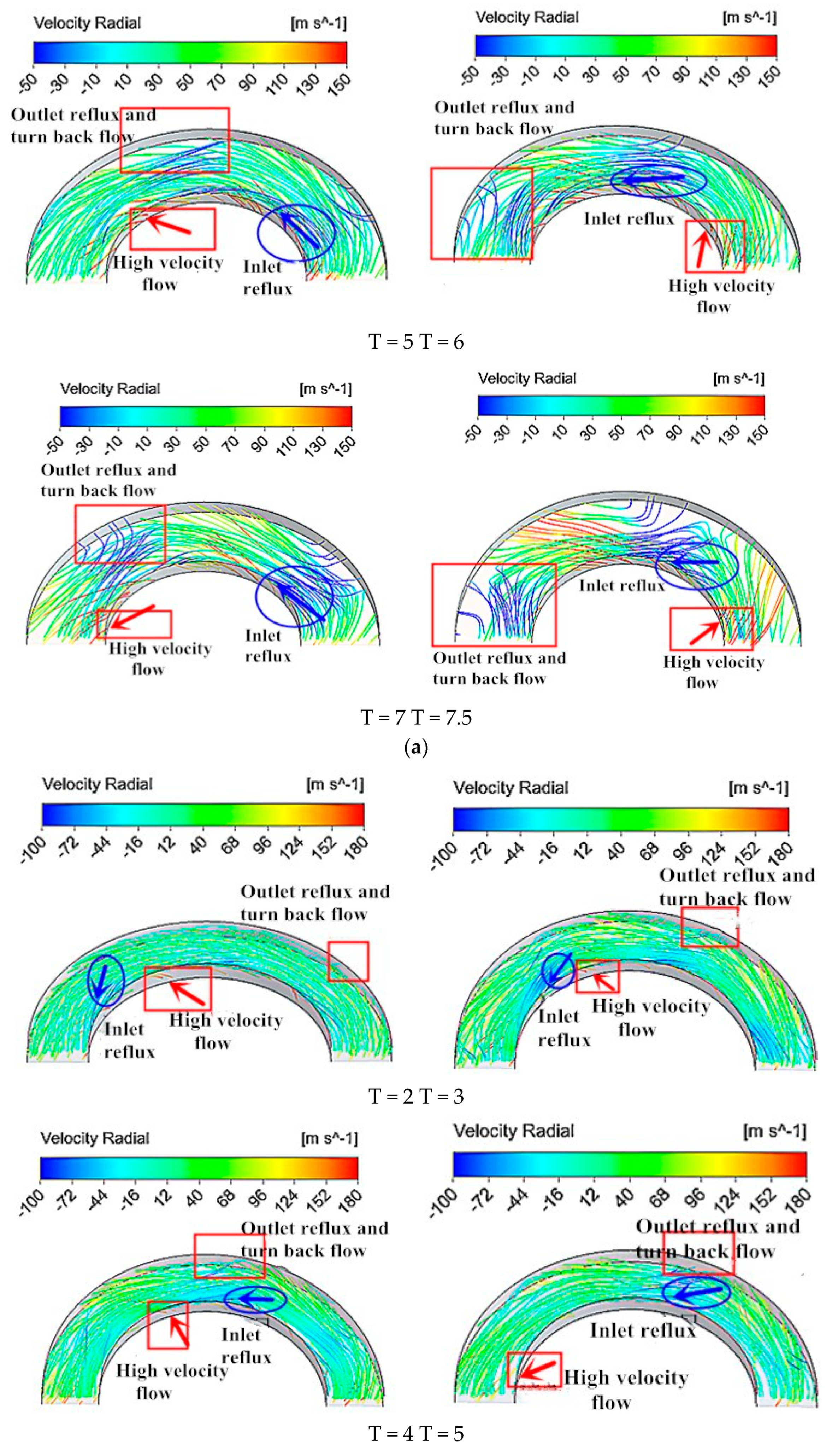
3.4. Analysis of Stall Mechanism

Through the above analysis, it is found that there are obvious differences in stall patterns during the process of the flow rate reduction for wide vaneless diffusers with different radius ratios, and the similarities and differences in the induction mechanism of different stall patterns are worth studying.
Figure 21 shows the three-dimensional streamline of two vaneless diffusers at different times under the stall onset flow rate. Whether the radius ratio is 1.8 or 1.5, the key factor in inducing stall is the same as the development of the outlet reflux, which leads to the core flow distortion of the diffuser. When the reflux develops to 50% of the blade height, the stall inception will be induced. Finally, the outlet reflux gradually develops to the hub side, forming a bigger reflux structure occupying the whole blade height, and the stable stall cells are formed.
As shown in Figure 22, the outlet reflux formed at the shroud side of the vaneless diffuser, resulting in the flow passage at the outlet of the diffuser shroud side. As the evolution of the flow field, the outlet reflux gradually develops along the radial and blade height direction at the same time. Finally, the outlet reflux develops along the blade height to the hub of the vaneless diffuser, and develops along the radial direction to the inlet, with the core flow blocked by reflux. When the outlet reflux and the inlet reflux converge, the reflux occupies the whole flow passage near the diffuser shroud, and the stall inception forms. Then, the stall inception develops for the whole flow passage of the diffuser along the radial and blade height direction, thus forming a stable stall cell.
Although the core flow instability causes the stall of wide vaneless diffusers with different radius ratios, the evolution laws of the stall are different. As shown in Figure 23, for a wide vaneless diffuser with a radius ratio of 1.8, the streamlines are long and need to travel far to enter the diffuser inlet. With the evolution of the flow field, the outlet reflux gradually expands and the streamlines become shorter. Finally, the streamlines do not cross the diffuser inlet directly along the radial direction, an “S” type indirect reflux structure forms, and the stable stall cell forms in the diffuser. For a wide vaneless diffuser with a radius ratio of 1.5, the streamline in the outlet reflux is relatively short and experiences a relatively short travel to enter the diffuser inlet. With the evolution of the flow field, the outlet reflux gradually expands and the streamlines become shorter. Finally, when the streamlines cross the diffuser inlet directly along the radial direction, a “1”-type direct return structure is formed, and a stable stall cell is formed in the diffuser.

4. Conclusions

From our study on the stall induction and evolution of two wide vaneless diffusers with different radius ratios, the main conclusions are as follows:
(1)
There are two kinds of rotating stall patterns in a centrifugal compressor with a wide vaneless diffuser. For the same backward centrifugal impeller, the number of stall cells does not change, with the flow rate decreasing when the diffuser radius ratio is 1.8, and the circumferential propagation speed of the stall cells presents a development process from low to high. When the radius ratio of the vaneless diffuser is 1.5, the circumferential velocity of the stall cells is larger. The number of stall cells does not change when the radius ratio is 1.5, and the circumferential propagation velocity of stall cells does not develop from low to high.
(2)
The stall frequency variations in wide vaneless diffusers with different radius ratios are different. For a long vaneless diffuser with a radius ratio of 1.8, the stall frequency increases gradually with the decrease in the flow rate. For a short vaneless diffuser with a radius ratio of 1.5, the stall frequency hardly changes with the flow rate.
(3)
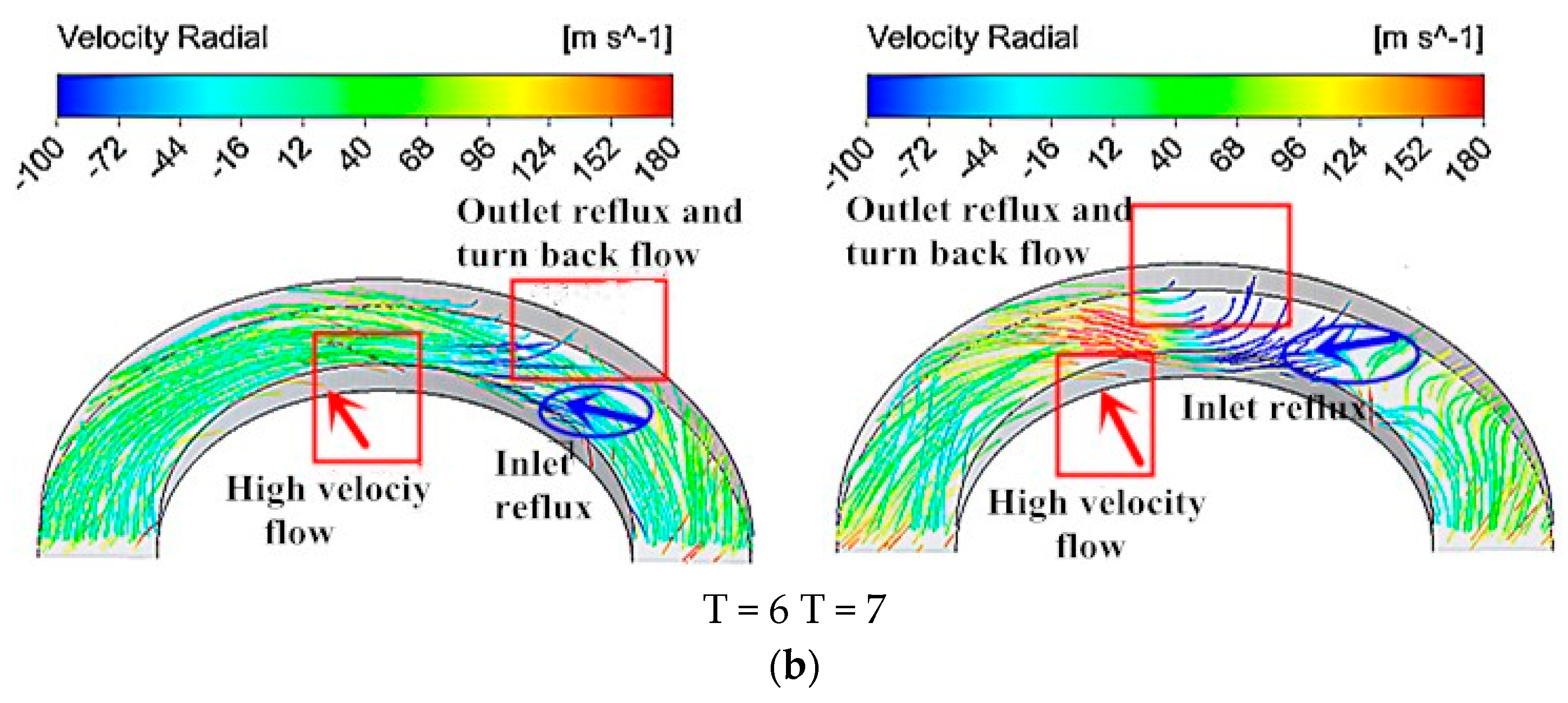
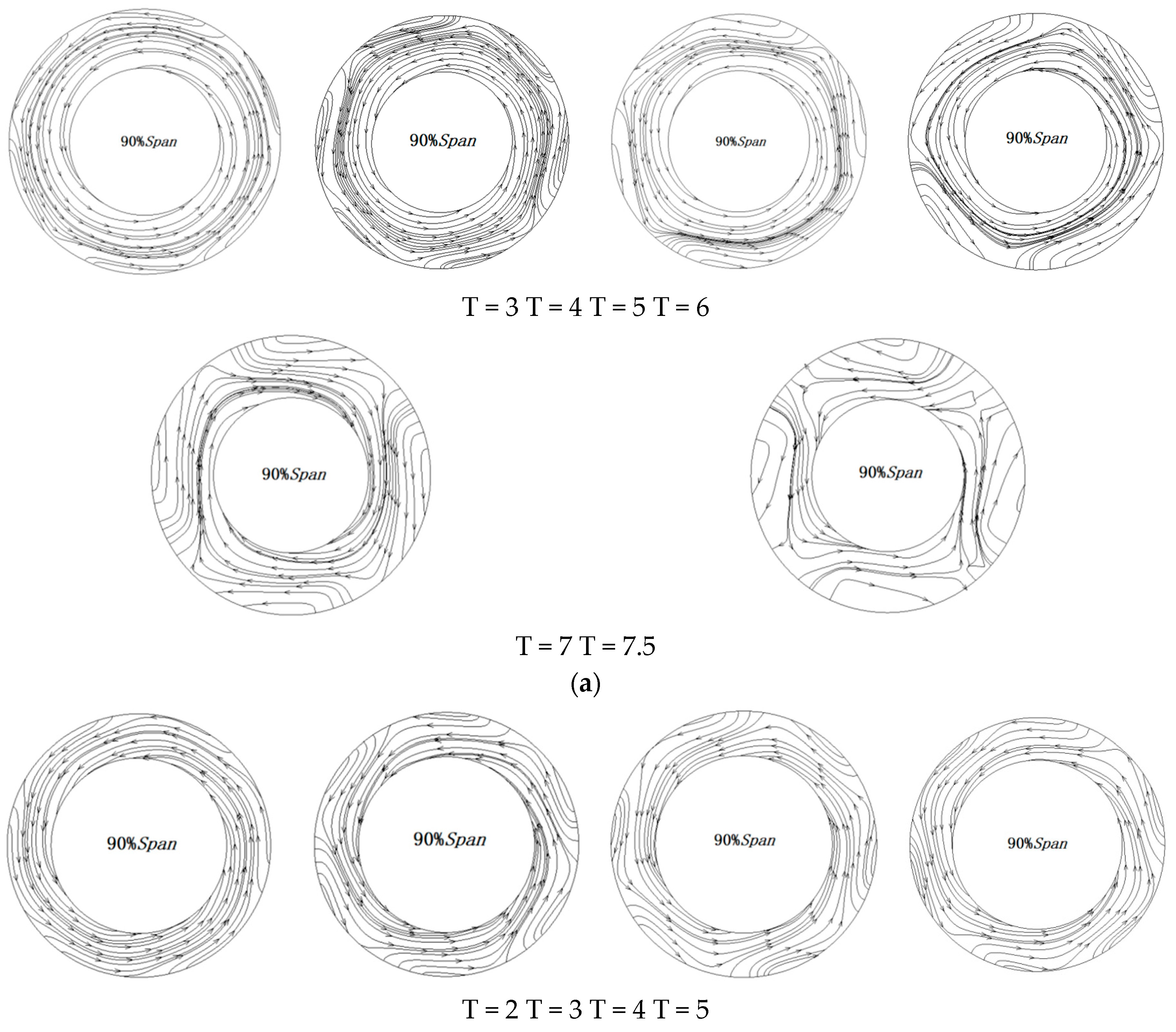
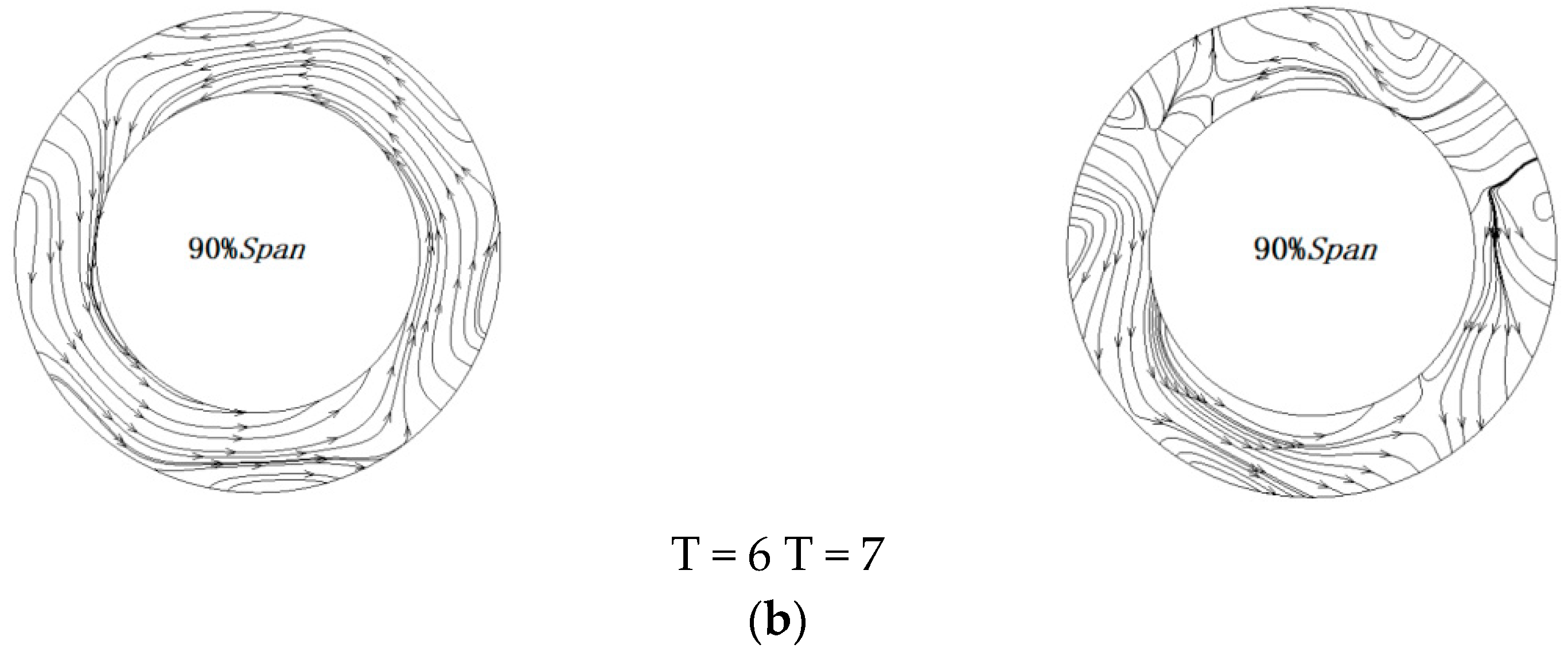
The key factors in stall induction in vaneless diffusers with different radius ratios are the same, but the processes of stall are different. For a wide vaneless diffuser with a centrifugal compressor, the development of the outlet reflux to the interior leads to the distortion of the core flow and induces the rotating stall finally. When the radius ratio of the diffuser is 1.8, it finally forms the “S”-type indirect reflux mode from the inlet to the outlet. When the radius ratio of the diffuser is 1.5, it forms the “1”-type direct reflux from the outlet to the inlet.
(4)
Reducing the radius ratio of a vaneless diffuser can increase the stability of the centrifugal compressor. When the radius ratio of a vaneless diffuser is reduced, the stall onset flow rate decreases, and the stable operation margin of the diffuser increases.

Author Contributions

Conceptualization, L.Z. (Liang Zhang) and L.Z. (Lei Zhang); methodology, L.Z. (Lei Zhang) and Q.Z.; software, L.Z. (Liang Zhang) and Q.H.; data curation, L.Z. (Liang Zhang); writing—original draft preparation, L.Z. data curation and Q.Z.; writing—review and editing, L.Z. (Lei Zhang) and Q.H.; supervision, L.Z. (Lei Zhang) and Q.Z.; funding acquisition, L.Z. (Lei Zhang). All authors have read and agreed to the published version of the manuscript.

Funding

This research was funded by National Natural Science Foundation of China (Grant No. 11602085); the Natural Science Foundation of Hebei Province, China (Grant No. E2020502013); and the Fundamental Research Funds for the Central Universities, China (Grant No. 2018MS107).

Conflicts of Interest

The authors declare no conflict of interest.

References

  1. Biliotti, D.; Bianchini, A.; Vannini, G.; Belardini, E.; Giachi, M.; Tapinassi, L.; Ferrari, L.; Ferrara, G. Analysis of the rotordynamic response of a centrifugal compressor subject to aerodynamic loads due to rotating stall. ASME J. Turbomach. 2015, 137, 021002. [Google Scholar] [CrossRef]
  2. Bianchini, A.; Biliotti, D.; Ferrara, G.; Ferrari, L.; Belardini, E.; Giachi, M.; Tapinassi, L.; Vannini, G. A systematic approach to estimate the impact of the aerodynamic force induced by rotating stall in a vaneless diffuser on the rotordynamic behavior of centrifugal compressors. ASME J. Eng. Gas Turbines Power 2013, 135, 112501. [Google Scholar] [CrossRef]
  3. Zhang, L.; He, R.; Wang, X.; Zhang, Q.; Wang, S. Study on static and dynamic characteristics of an axial fan with abnormal blade under rotating stall conditions. Energy 2019, 170, 305–325. [Google Scholar] [CrossRef]
  4. Kang, J.X.; Huang, G.P.; Zhu, J.Q.; Wen, D.-Z. Stall mode of centrifugal compressor and mechanism of self-recirculating casing treatment. J. Aerosp. Power 2015, 30, 2960–2969. [Google Scholar]
  5. Zhang, L.; Zheng, Z.; Zhang, Q.; Zhang, L.; Li, K. Study of Rotating Stall in a Centrifugal Compressor with Wide Vaneless Diffuser. J. Therm. Sci. 2020, 29, 743–752. [Google Scholar] [CrossRef]
  6. Jansen, W. Rotating Stall in a Radial Vaneless Diffuser. J. Basic Eng. 1964, 86, 750–758. [Google Scholar] [CrossRef]
  7. Senoo, Y.; Kinoshita, Y.; Ishida, M. Asymmetric Flow in Vaneless Diffusers of Centrifugal Blowers. Trans. Jap. Soc. Mech. Eng. 1977, 43, 987–996. [Google Scholar] [CrossRef] [Green Version]
  8. Senoo, Y.; Kinoshita, Y. Influence of Inlet Flow Conditions and Geometries of Centrifugal Vaneless Diffusers on Critical Flow Angles for Reverse Flow. Trans. ASME J. Fluids Eng. 1977, 99, 98–103. [Google Scholar] [CrossRef]
  9. Abdelhamid, A.N. Analysis of Rotating Stall in Vaneless Diffusers of Centrifugal Compressors. Can. Aero. Space J. 1980, 26, 118–128. [Google Scholar]
  10. Tsujimoto, Y.; Yoshida, Y.; Mori, Y. Study of vaneless diffuser rotating stall based on two-dimensional inviscid flow analysis. ASME J. Fluids Eng. 1996, 118, 123–127. [Google Scholar] [CrossRef]
  11. Dou, H.S.; Mizuki, S. Analys of the Flow in Vaneless Diffuser with Large Width to Radius Ratios. J. Turbomach. 1998, 120, 194–201. [Google Scholar] [CrossRef]
  12. Ljevar, S.; Lange, H.C.D.; Van Steenhoven, A.A. Two-dimensional rotating stall analysis in a wide vaneless diffuser. Int. J. Rotat. Mach. 2006, 2006, 1–11. [Google Scholar] [CrossRef]
  13. Shin, Y.H.; Kim, K.H.; Son, B.J. An experimental study on the development of a reverse flow zone in a vaneless diffuser. ASME Int. J. Ser. B Fluids Therm. Eng. 1998, 41, 546–555. [Google Scholar] [CrossRef] [Green Version]
  14. Abdelhamid, A.N.; Colwill, W.H.; BaIrrows, J.E. Experimental investigation of unsteady phenomena in vaneless radial diffusers. J. Eng. Gas Turb. Power 1979, 101, 52–59. [Google Scholar] [CrossRef]
  15. Abdelhamid, A.N. Effects of vaneless diffuser geometry on flow instability in centrifugal compression systems. Can. Aero. Space J. 1983, 29, 259–266. [Google Scholar]
  16. Dazin, A.; Gavazzini, G.; Pavesi, G.; Dupont, P.; Coudert, S.; Ardizzon, G.; Caignaert, G.; Bois, G. High-speed stereoscoipc PIV study of rotating instabilities in a radial vaneless diffuser. Exp. Fluids 2011, 51, 83–93. [Google Scholar] [CrossRef]
  17. Chu, W.L.; Jiang, T. An Experimental investigation of rotating stall in a centrifugal compressor with vaneless diffuser. J. Aerosp. Power 1990, 5, 163–165. [Google Scholar]
  18. Shen, F.; Chen, H.; Zhu, X.C. A three-dimensional vaneless diffuser stall model. Proc. Inst. Mech. Eng. Part C J. Mech. Eng. Sci. 2010, 224, 1933–1945. [Google Scholar] [CrossRef]
  19. Halawa, T.; Alqaradawi, M.; Badr, O.; Gadala, M.S. Numerical Investigation of Rotating Stall in Centrifugal Compressor with Vaned and Vaneless Diffuser. J. Therm. Sci. 2015, 4, 323–333. [Google Scholar] [CrossRef]
  20. Halawa, T.; AlQaradawi, M.; Badr, O.; Gadala, M.S. Numerical simulation and control of rotating stall in a transonic centrifugal compressor. In Proceedings of the ASME 12th Biennial Conference on Engineering Systems Design and Analysis, Copenhagen, Denmark, 25–27 July 2014; ASME: New York, NY, USA; p. 11. [Google Scholar]
  21. Zhu, X.C.; Hu, X.C.; Du, Z.H. Formation and suppression of the instability in radial vaneless diffusers. Proc. Inst. Mech. Eng. Part G-J. Aerosp. Eng. 2019, 12, 4606–4622. [Google Scholar] [CrossRef]
  22. Ötügen, M.V.; So, R.M.C.; Hwang, B.C. Diffuser stall and rotating zones of separated boundary layer. Exp. Fluids 1988, 6, 521–533. [Google Scholar] [CrossRef]
  23. Grapow, F.; Liskiewicz, G. Three-Dimensional Vaneless Diffuser Rotating Stall Numerical Study; ASME Turbo Expo: Oslo, Norway; ASME: New York, NY, USA, 2018; pp. 11–15. [Google Scholar]
  24. Zhang, L.; He, R.Y.; Wang, S.L.; Zhang, Q. A Review of Rotating Stall in Vaneless Diffuser of Centrifugal Compressor. J. Therm. Sci. 2020, 29, 323–342. [Google Scholar] [CrossRef]
  25. Hu, C.; Yang, X.; Zhu, X.; Du, Z. Stability and structural sensitivity analysis of the turbulent flow in the narrow vaneless diffuser with mean flow method. Comput. Fluids 2018, 30, 46–57. [Google Scholar] [CrossRef]
  26. Zhang, L.; Zhang, L.; Zhang, Q.; Jiang, K.; Tie, Y.; Wang, S. Effects of the second-stage of rotor with single abnormal blade angle on rotating stall of a two-stage variable pitch axial fan. Energies 2018, 11, 3293. [Google Scholar] [CrossRef] [Green Version]
  27. Menter, F.R. Two-Equation Eddy-Viscosity Turbulence Models for Engineering Applications. AIAA J. 1994, 32, 1598–1605. [Google Scholar] [CrossRef] [Green Version]
  28. Krain, H.; Hoffmann, W. Verification of an Impeller Design by Laser Measurements and 3D-Viscous Flow Calculations. In Proceedings of the ASME 1989 International Gas Turbine and Aeroengine Congress and Exposition, Toronto, ON, Canada, 4–8 June 1989; ASME: New York, NY, USA; pp. 1–9. [Google Scholar]
Figure 1. Geometry of the centrifugal compressor: (a) the centrifugal impeller, (b) the vaneless diffuser.
Processes 08 01251 g001
Figure 2. Grid of the centrifugal impeller and single channel: (a) grid of the centrifugal impeller, (b) grid of a single channel, (c) grid of a partial single channel, (d) grid of a partial single channel.
Processes 08 01251 g002
Figure 3. The grid independence verification of the centrifugal compressor.
Processes 08 01251 g003
Figure 4. Experiment and simulation results of the Krain impeller [28].
Processes 08 01251 g004
Figure 5. The compressor performance curve of the flow rate and pressure ratio.
Processes 08 01251 g005
Figure 6. Probe position in the 50% span section of the vaneless diffuser.
Processes 08 01251 g006
Figure 7. Relative velocity curve of the monitoring point when the flowrate is 1.1 kg/s: (a) the curve of relative velocity at 8 points; (b) the curve of relative velocity at 3 adjacent points.
Processes 08 01251 g007
Figure 8. Relative velocity curve of the monitoring point when the flowrate is 1.0 kg/s: (a) The curve of relative velocity at 8 points; (b) the curve of relative velocity at 3 adjacent points.
Processes 08 01251 g008
Figure 9. Relative velocity curve of the monitoring point when the flowrate is 0.9 kg/s: (a) the curve of the relative velocity at 8 points; (b) the curve of the relative velocity at 3 adjacent points.
Processes 08 01251 g009
Figure 10. Relative velocity curve of the monitoring point when the flowrate is 0.8 kg/s: (a) the curve of the relative velocity at 8 points; (b) the curve of the relative velocity at 3 adjacent points.
Processes 08 01251 g010
Figure 11. Relative velocity curve of the monitoring point when the flowrate is 0.6 kg/s: (a) the curve of the relative velocity at 8 points; (b) the curve of the relative velocity at 3 adjacent points.
Processes 08 01251 g011
Figure 12. Frequency domain characteristic curve of S1 under different stall flow conditions: (a) the flowrate is 1.1 kg/s, (b) the flowrate is 0.9 kg/s, (c) the flowrate is 0.6 kg/s
Processes 08 01251 g012
Figure 13. The compressor performance curve of the flow rate and pressure ratio.
Processes 08 01251 g013
Figure 14. Relative velocity curve of the monitoring point when the flowrate is 1.0 kg/s: (a) the curve of the relative velocity at 8 points; (b) the curve of the relative velocity at 3 adjacent points.
Processes 08 01251 g014
Figure 15. Relative velocity curve of the monitoring point when the flowrate is 0.8 kg/s: (a) the curve of the relative velocity at 8 points; (b) the curve of the relative velocity at 3 adjacent points.
Processes 08 01251 g015
Figure 16. Relative velocity curve of the monitoring point when the flowrate is 0.7 kg/s: (a) rhe curve of the relative velocity at 8 points; (b) the curve of the relative velocity at 3 adjacent points.
Processes 08 01251 g016
Figure 17. Relative velocity curve of the monitoring point when the flowrate is 0.6 kg/s: (a) the curve of the relative velocity at 8 points; (b) the curve of the relative velocity at 3 adjacent points.
Processes 08 01251 g017
Figure 18. Frequency domain characteristic curve of S1 under different stall flow conditions: (a) the flowrate is 1.0 kg/s, (b) the flowrate is 0.8 kg/s, (c) the flowrate is 0.7 kg/s.
Processes 08 01251 g018aProcesses 08 01251 g018b
Figure 19. The number of stall cells, the circumferential propagation velocity ratio, and the stall frequency changed with the flow rate: (a) the stall cell numbers and the circumferential velocity ratio; (b) the stall frequency.
Processes 08 01251 g019
Figure 20. Experiment results of Abdehamid [14]: (a) the change in the stall cell propagation velocity with the flow coefficient; (b) the change in the stall cell circumferential propagation velocity with the radius ratio under the onset of stall.
Processes 08 01251 g020
Figure 21. The streamline of vaneless diffusers with different radius ratios: (a) the streamline of a vaneless diffuser with a radius ratio of 1.8; (b) the streamline of a vaneless diffuser with a radius ratio of 1.5.
Processes 08 01251 g021aProcesses 08 01251 g021bProcesses 08 01251 g021c
Figure 22. Radial velocity contour of different blade height sections at different times: (a) the diffuser radius ratio is 1.8; (b) the diffuser radius ratio is 1.5.
Processes 08 01251 g022aProcesses 08 01251 g022b
Figure 23. The suction streamline of vaneless diffusers in different times: (a) streamline of the 90% diffuser blade height at different times when the radius ratio is 1.8; (b) streamline of the 90% diffuser blade height at different times when the radius ratio is 1.5.
Processes 08 01251 g023aProcesses 08 01251 g023b
Table 1. Main structural parameters of the centrifugal compressor.
ParameterValueParameterValue
Inlet total pressure (pa)101,325Inlet total temperature (K)293.15
Designed flowrate (kg/s)2.0Designed pressure ratio2.5
Designed rotating speed (r/min)45,000Tip clearance (mm)0.3
Hub radius of leading edge (mm)25.5Tip radius of leading edge (mm)40
Impeller outlet radius (mm)93Relative outlet width of impeller (r2/b2)0.1633
Outlet radius of diffuser 1 (mm)139.5Outlet radius of diffuser 2 (mm)167.4

