Article

Design and Implementation of a Hybrid Real-Time State of Charge Estimation Scheme for Battery Energy Storage Systems

Department of Electrical Engineering, CEECS, National United University, Miaoli 36063, Taiwan
Processes 2020, 8(1), 2; https://doi.org/10.3390/pr8010002
Submission received: 29 October 2019 / Revised: 9 December 2019 / Accepted: 16 December 2019 / Published: 18 December 2019
(This article belongs to the Special Issue Energy Storage System: Integration, Power Quality, and Operation)

Abstract

:
In order to maximize the operating flexibility and optimize the system performance of a battery energy storage system (BESS), developing a reliable real-time estimation method for the state of charge (SOC) of a BESS is one of the crucial tasks. In practice, the accuracy of real-time SOC detection can be interfered with by various factors, such as battery’s intrinsic nonlinearities, working current, temperature, and aging level, etc. Considering the feasibility in practical applications, this paper proposes a hybrid real-time SOC estimation scheme for BESSs based on an adaptive network-based fuzzy inference system (ANFIS) and Coulomb counting method, where a commercially available lead-acid battery-based BESS is used as the research target. The ANFIS allows effective learning of the nonlinear characteristics in charging and discharging processes of a battery. In addition, the Coulomb counting method with an efficiency adjusting mechanism is simultaneously used in the proposed scheme to provide a reference SOC for checking the system reliability. The proposed estimating scheme was first simulated in a Matlab software environment and then implemented with an experimental hardware setup, where an industrial-grade digital control system using DS1104 as the control kernel and dSPACE Real-Time Interface (RTI) interface were used. Results from both simulation and experimental tests verify the feasibility and effectiveness of the proposed hybrid SOC estimation algorithm.

1. Introduction

In recent years, BESSs have been widely used in renewable energy (RE)-based power generation (REBPG) applications and microgrids to smooth the intermittent power generation, buffer the power generation–demand differences, and improve the frequency stability of power systems. BESSs are also very useful in optimal electrical energy management and grid voltage stabilization [1]. In order to achieve proper compensation functions, real-time SOC information of BESS is required to determine its operational limits and prevent overcharging/overdischarging to ensure a desirable battery life. In practice, there are many factors that affect battery’s SOC, including battery current, ambient temperature, electrolyte concentration, internal impedance, and aging level, etc. It is indeed difficult to estimate accurately the battery’s SOC using existing SOC estimation techniques. Moreover, most of the existing SOC estimation techniques are only suitable for experimental analysis performed in a laboratory and may not be applicable in online estimation of battery SOC. To have a general understanding of the existing methods and the related algorithms, some of the reported SOC estimation methods are reviewed in the following part of this section.
Coulomb counting method [2,3,4] is based on the law of energy conservation. Through real-time sensing of battery current and the current integration over time, SOC variations can be determined. As a result, real-time SOC can be determined based on a given initial SOC value. This process can be expressed as (1):
SOC ( t ) = SOC 0 + [ t 0 t K · i ( t ) d t ] / Q r ,
where SOC(t) represents real-time SOC, SOC0 represents the initial SOC, Qr represents battery capacity, K is the charging or discharging efficiency adjusting factor, and i(t) represents battery current. This method is simple and easy to apply when initial SOC is known. However, factors such as ambient temperature and battery aging level can cause significant error over time. Consequently, certain adjusting factors are usually needed, or other estimation methods can be combined, to improve estimation accuracy.
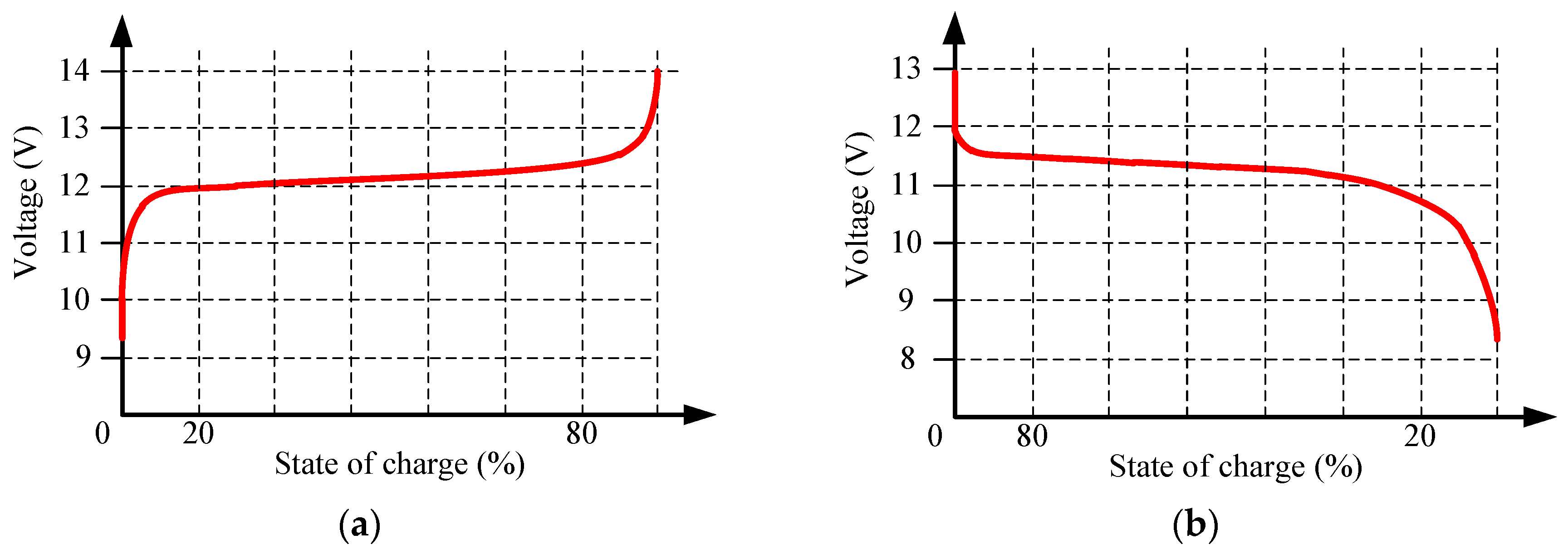
Open-circuit voltage (OCV) methods [5,6,7] can be used to estimate battery SOC using the approximately proportional relationship between battery OCV and SOC. The key to this method is that when measuring the OCV, the battery must be disconnected from any load, and the distribution of internal electrolyte concentration must be uniform. During charging, the electrolyte concentration near the electrode plates is high; when discharging, the electrolyte concentration near the electrode plates is low. Therefore, after several times of charging/discharging operations, the distribution of electrolyte concentration is not uniform, and thus the OCV is not stable. In order to accurately measure the OCV, the battery must stop working for a while. At different charging/discharging rates, the chemical reaction speed of the electrolyte is different, so the required diffusion time is also variable. When electrolyte concentration returns to uniform distribution, the measured OCV can then accurately correspond to the real battery SOC. Due to the fact that this method requires a no-load condition, it is not suitable for practical applications. Furthermore, factors similar to those in the Coulomb counting method can cause errors in this method as well.
The internal resistance method [8,9,10] estimates battery SOC by measuring the changes in the internal resistance of the battery. Different battery internal structures generate different resistances when current passes through, which is the reason why ideal battery capacities do not match actual operating capacities. By measuring the battery current and voltage drop, the internal resistance can be calculated. The positive correlation between internal resistance and battery SOC can then be found through experiments and used for SOC estimation. The variation in the internal resistance of a battery is normally very small (mΩ level), and thus a measuring device with relatively high accuracy is required. In addition, the internal resistance of a battery is also affected by ambient temperature, aging level, etc., so this method is more suitable for battery state of health (SOH) assessment performed in laboratory.
The load voltage method [10,11] estimates battery SOC by measuring battery terminal voltage when the battery is connected to a load. When using this method, in addition to battery characteristics and SOH, terminal voltage sags and swells due to internal resistance should also be considered. Therefore, the influence of battery current variation on SOC estimation must also be taken into consideration. In addition, when battery SOC is around 20–10%, the terminal voltage tends to drop exponentially. As a result, this method is not suitable for a BESS whose load is constantly changing. This method is generally used in BESS equipment with low accuracy requirements.
The electrolyte concentration of batteries increases/decreases when charged/discharged. Theoretically, there is a linear relationship between the concentration of the electrolyte and battery SOC. Therefore, the SOC can be estimated by measuring battery electrolyte concentration. Similar to internal resistance method, before measuring it is necessary to let the battery rest and the electrolyte to distribute evenly after charging/discharging. Moreover, some fully sealed batteries cannot be installed with a hydrometer. As a result, this method is more suitable for experimental testing of batteries when they are not in operation [10].
The electrochemical impedance spectroscopy (EIS) method [12] uses small AC voltage or current to perturb the electrodes for estimating the SOC. AC impedance data are obtained from experiments, and the corresponding electrode reaction parameters can be calculated according to equivalent circuit of the batteries. To have a whole picture of the above mentioned conventional SOC-detecting methods, Table 1 summarizes their advantages and disadvantages.
To overcome the disadvantages of the above methods summarized in Table 1, researchers have proposed nonlinear methods, e.g., extended Kalman filter (EKF) [13,14], unscented Kalman filter (UKF) [15,16], particle filter [17,18], Bayesian framework [19,20], sliding mode [21,22], nonlinear observer [23,24], wavelet analysis [25,26], and H-infinity [27,28,29]. These methods are applicable to any battery and can simultaneously identify the parameters of prebuilt models and thereby estimate battery SOC through their nonlinear mapping capabilities without the need of initial SOC values. However, the required models may need to be adjusted or rebuilt when battery characteristics change, and the complexity of the models will significantly affect their SOC-estimating performance. On the other hand, some researchers have proposed intelligent algorithms for SOC estimation, such as artificial neural network (ANN) [30,31,32], fuzzy logic [33,34,35], support vector [36,37], and adaptive network-based fuzzy inference system (ANFIS) [38,39,
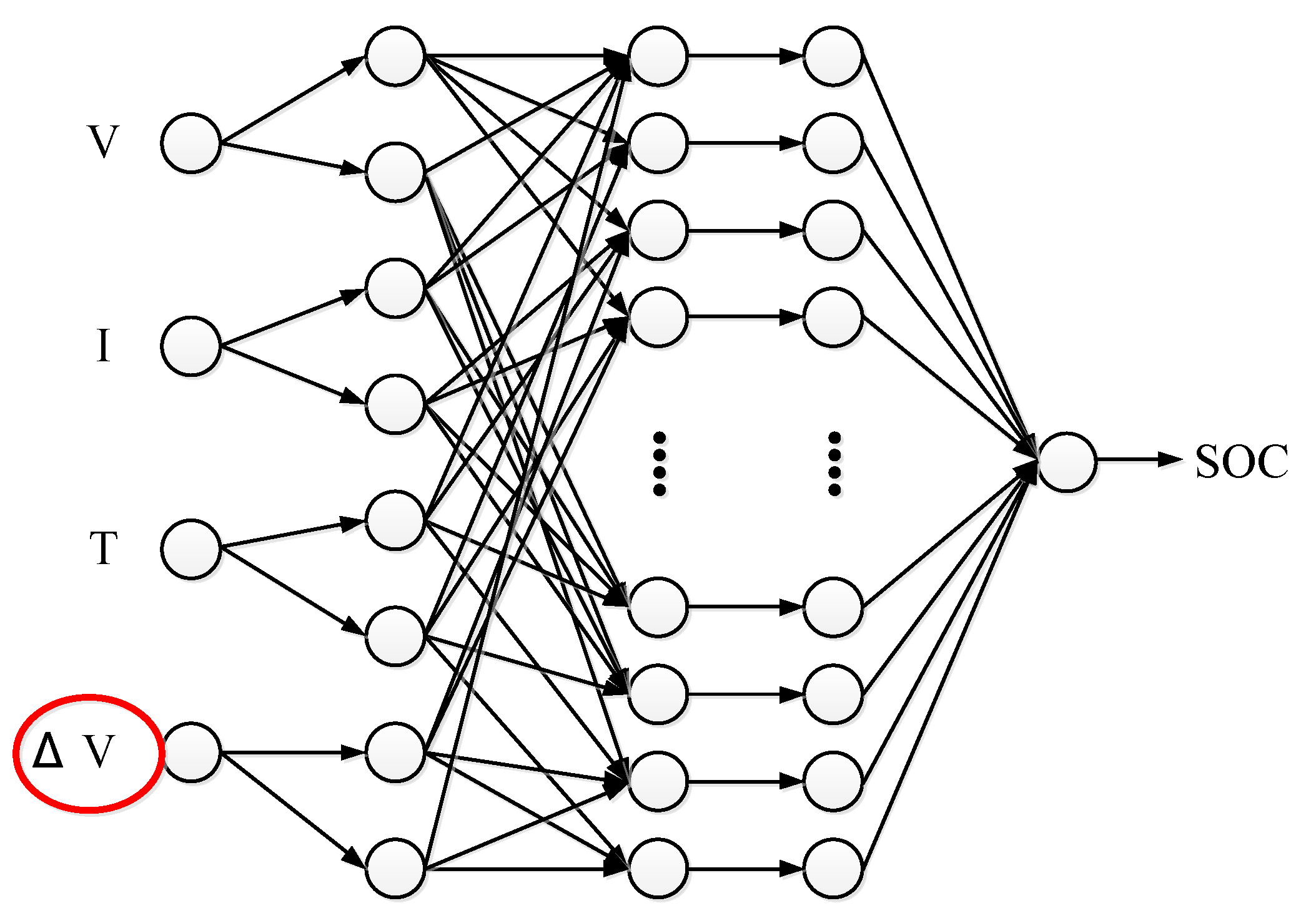
40]. These methods do not require complicated equivalent circuits or models for obtaining the nonlinear characteristics of batteries, instead it is done through their learning and inference capabilities. In [
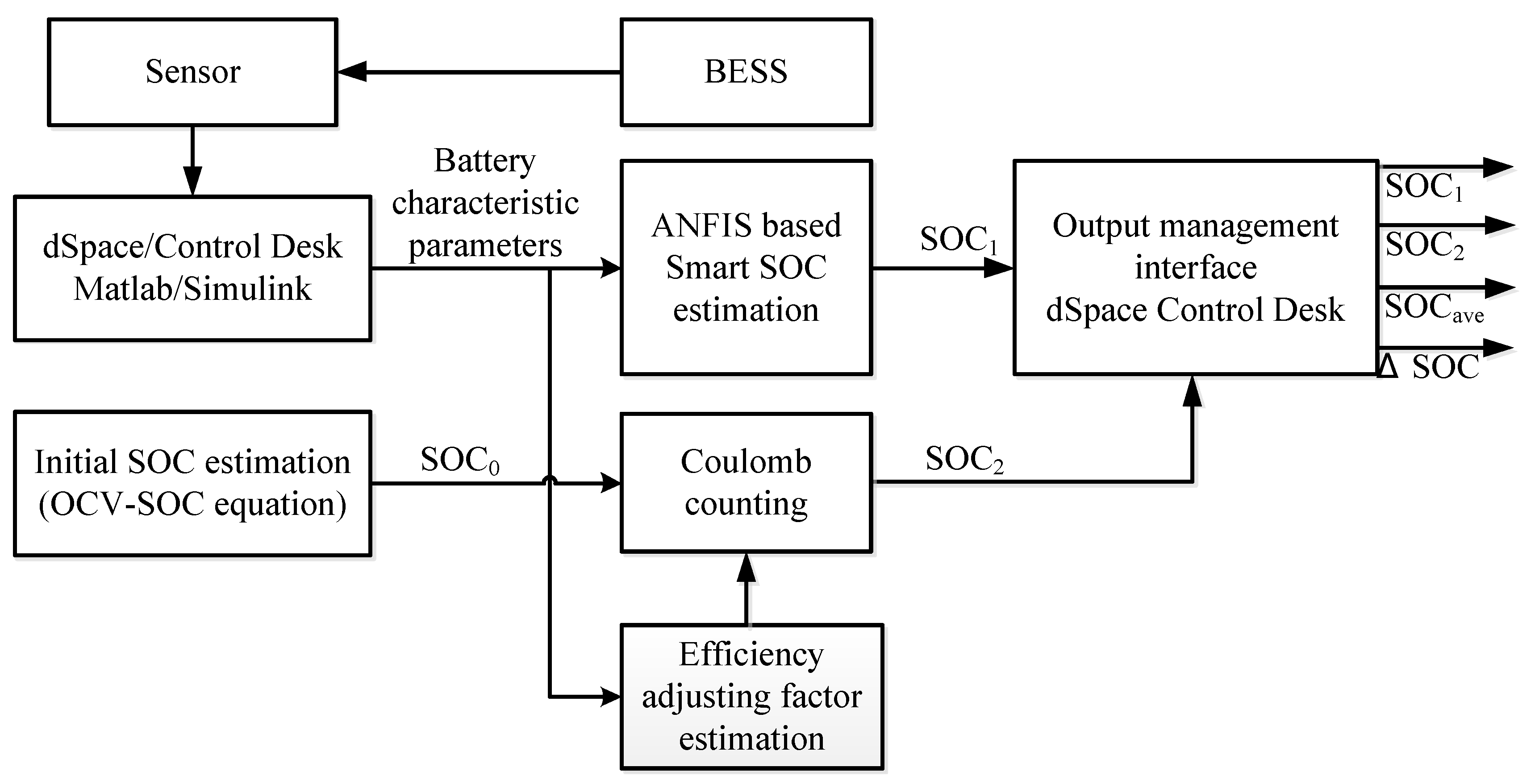
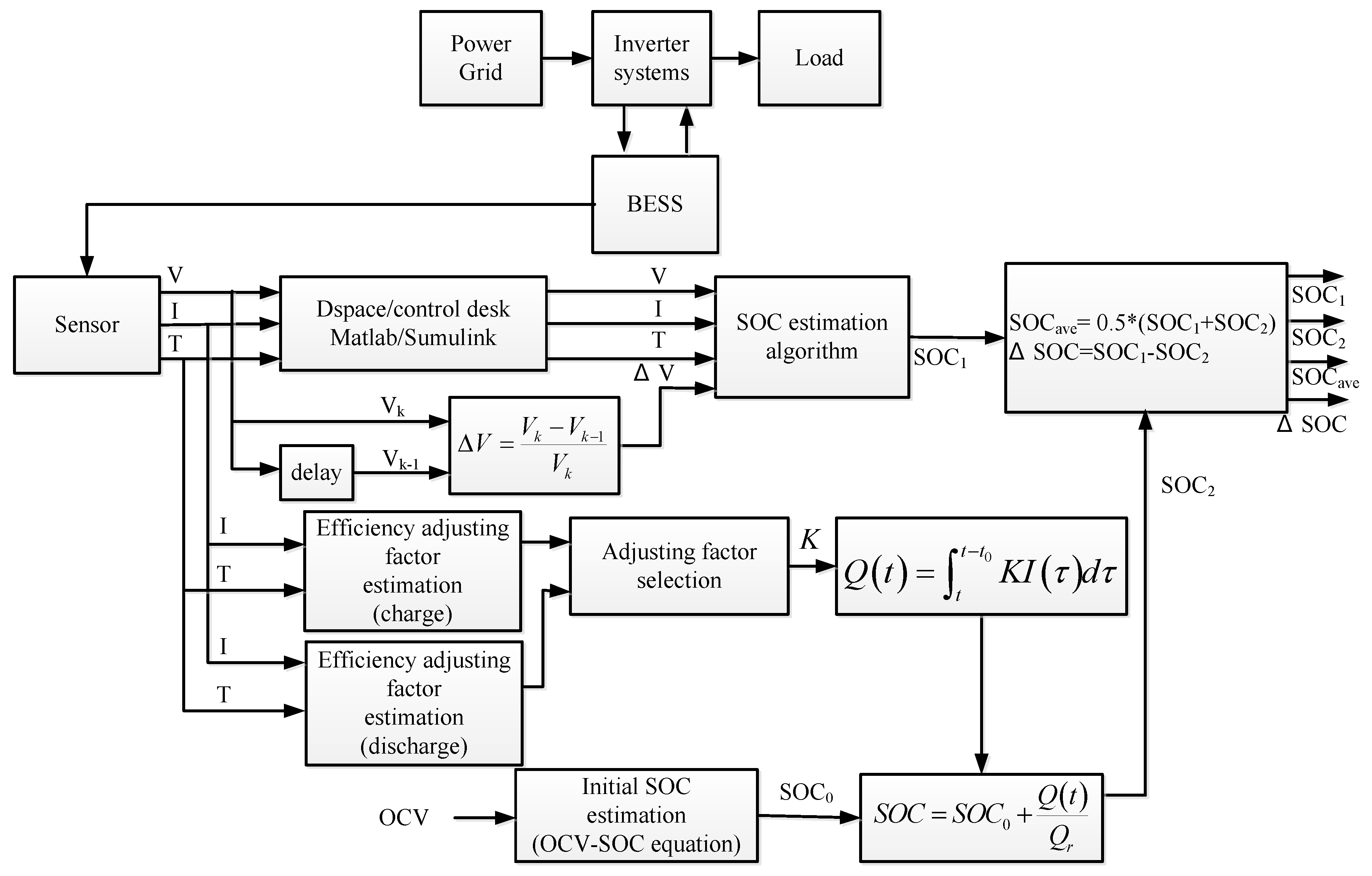
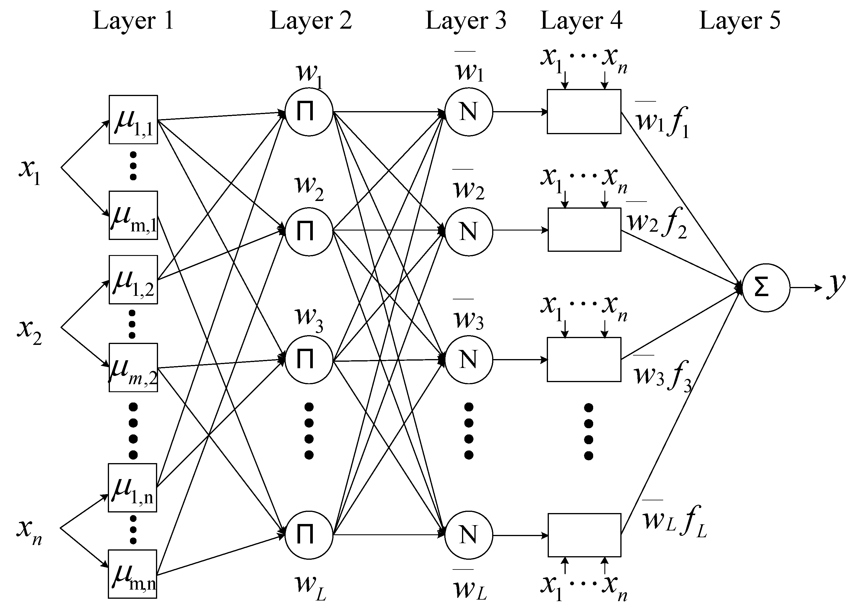
41], an ANFIS architecture was proposed to process a large number of battery characterization data through repeated charge/discharge experiments. These data were then used for battery’s SOC estimation. The above mentioned ANN and ANFIS-based SOC estimating methods are relatively easy in implementation but they have a common drawback, i.e., the reliability of estimation cannot be fully guaranteed. To improve the estimation reliability, this paper proposes a hybrid real-time battery SOC estimation scheme for practical applications, where two detecting methods, adaptive Coulomb counting method and ANFIS-based online estimating algorithm, are integrated to constitute a hybrid SOC estimation scheme. In the proposed scheme, ANFIS is used to effectively learn the nonlinear mapping relationships among the SOC and characteristic parameters of a battery during charging and discharging processes. An adaptive Coulomb counting algorithm is simultaneously used to produce a real-time estimated SOC values for double checking the correctness of the SOC estimation of ANFIS. It can be expected that the proposed hybrid SOC-detecting scheme with parallel estimating mechanisms and multiple SOC results can effectively increase the reliability of SOC monitoring.
Following this section, the next section explains the proposed hybrid SOC estimation scheme and briefly introduces the ANFIS principle. The third section introduces the arrangement of battery experiments and the method used to obtain characteristic parameters, describes the battery measurement experiment platform, and analyzes the obtained parameters. In addition, this section also explains how to establish an ANFIS in a MATLAB environment, and the correctness of the SOC estimation scheme is verified through simulations. An inverter integrated BESS hardware setup is explained in the fourth section for further verifying the proposed hybrid real-time SOC estimation scheme via experimental tests. A real-time digital control system was developed with the dSPACE DS1104 platform, and three test cases were carried out. Finally, a conclusion is drawn in the fifth section.

2. Proposed Hybrid Real-Time SOC Estimation Scheme

2.1. System Design, Working Principle, and Design of Training Mechanism

The hybrid real-time SOC estimation scheme proposed in this paper utilizes the parallel computing capability of ANFIS to simultaneously process multiple battery characteristic parameters and establish the relationships between selected battery parameters and battery SOC in a manner similar to the nonlinear mapping of a multiple input and single output system. Due to the fact that the structure of decentralized memory is adopted in ANFIS, fault tolerance capability is relatively high. Through the adaptive learning and nonlinear inference capabilities of the ANFIS algorithm, battery SOC can be effectively estimated. The hybrid SOC-detecting mechanism proposed in this paper was designed with the above-mentioned intelligent algorithm and Coulomb counting method, as shown in Figure 1. When operating online, the system senses relevant battery characteristic parameters and then inputs those parameters to the ANFIS-based SOC estimator to obtain the real-time SOC value (SOC1). At the same time, the Coulomb counting method with online adjusting factors is simultaneously activated to provide a second SOC result (SOC2) in the proposed scheme. In practical operation with the proposed method, multiple estimated SOC results, the estimation on ANFIS (SOC1), the estimation on adaptive Coulomb counting algorithm (SOC2), the average of the above two estimation results (SOCave), and the difference between the two estimation results (ΔSOC) can be obtained for monitoring battery’s status. If the difference between the two estimated SOC values (ΔSOC) exceeds a certain threshold, it means that the detecting results may need to be reexamined.
The battery characteristic parameters selected for the proposed ANFIS algorithm include battery voltage, current, and temperature. Voltage slew rate (ΔV) is also included to improve the performance of the algorithm. These experimental data can be obtained through experiments and provided for offline learning. When the learning is complete, the correctness of the algorithm can be verified through simulation. S-function is used to implement the calculation processes, and the battery SOC estimation algorithm module is built for online real-time applications. The initial SOC value required by the Coulomb counting method is obtained using the OCV method and a linear approximation equation is established from the battery manufacturer’s OCV-SOC data. The formula for calculating real-time battery SOC using Coulomb counting algorithm is shown in (1).
As can be seen in the charge and discharge curves of a battery shown in Figure 2, both sides of the SOC-V curves exhibit nonlinear characteristics and are referred to as the exponential zones, while the middle section is called the linear zone, which is usually defined as 10–95% of battery’s SOC. Due to that fact, the battery voltage changes quite rapidly in the exponential zones but relatively slowly in the linear zone. As a result, the section where the SOC is located can be judged by voltage slew rate within a sampling interval, and the sensitivity of SOC to battery voltage can be further improved according to this information. Voltage slew rate (ΔV) in this paper is defined as follows:
Δ V = ( V k V k - 1 ) / V k ,
where Vk represents the current voltage and Vk−1 represents the previous sampled voltage. The designed ANFIS configuration for SOC estimation is shown in Figure 3 and the block diagram of the full detecting algorithm is shown in Figure 4. In the proposed algorithm, the efficiency adjusting factors (K) are used to compensate for the usable capacity variation due to battery current, ambient temperature, and aging level; they are calculated as follows:
K d i s c h a r g e = Q r / Q u s e ;
K c h a r g e = Q u s e / Q r ,
where Quse and Qr represent, respectively, the actual usable and the rated capacity.

2.2. Adaptive Network Based Fuzzy Inference System

The composition of an ANFIS system includes fuzzy inference and ANN [26,27,28]. A fuzzy inference system simulates a human’s knowledge and logical inference process with if–then conditionality but requires expert knowledge or empirical rules to constantly adjust the membership functions and fuzzy rules to obtain optimal parameters, so that there is no definite quantitative analysis and numerical correction processes. On the other hand, although ANN cannot handle human knowledge and logical reasoning processes, it has self-learning and organization capabilities. Therefore, ANFIS can make use of ANN’s features to deal with uncertainty and inaccuracy, perform self-learning, and adjust network parameters to achieve parameter optimization.
The ANFIS configuration used in this paper is shown in Figure 5, which is a five-level network structure where each node has similar function. Oh,k denotes the output of the k-th rule in the k-th layer, xi represents input variable, uji represents fuzzy set, wk represents rule layer output, w ¯ k represents the output of the normalized rule layer, fk represents a one-order Sugeno equation, and y represents the sum of the inference results.
In the first layer, which is the input layer, the inputs are mapped into the fuzzy sets. Here, a Gaussian function is chosen as the mapping function:
O 1 , j i = μ j ( x i ) = exp [ ( x i c j i ) 2 / 2 σ j i 2 ] ,   f o r   i = 1 , 2 , n ;   j = 1 , 2 , , m ,
where uj,i represents the membership function of the j-th set with the i-th input variable, σji represents standard deviation, and cji represents maximum value of Gaussian function.
In the second layer, which is the rule layer, the fuzzy sets are arranged using a total of L rules for fuzzy logic calculation, and T-norm is adopted for fuzzy AND operation. There are many T-norm operations, and multiplication is used in this paper. Supposing that the network has two sets and two inputs per set, then we have a network with four rules. The set of calculations is as follows:
O 2 , 1 = w 1 = μ 1 , 1 ( x 1 ) · μ 1 , 2 ( x 2 ) O 2 , 2 = w 2 = μ 1 , 1 ( x 1 ) · μ 2 , 2 ( x 2 ) O 2 , 3 = w 3 = μ 2 , 1 ( x 1 ) · μ 1 , 2 ( x 2 ) O 2 , 4 = w 4 = μ 2 , 1 ( x 1 ) · μ 2 , 2 ( x 2 )
In the third layer, which is the normalization layer, all node outputs of the second layer are normalized through the calculation of the ratio of k-th output to the sum of all outputs, so that every output value is between 0 and 1:
O 3 , k = w ¯ k = w k / k = 1 L w k ,   f o r   k = 1 , 2 , , L .
In the fourth layer, which is the inference layer, the outputs of the third layer are multiplied by the Sugeno inference algorithm:
O 4 , k = w ¯ k f k = w ¯ k ( p k x 1 + q k x 2 + r k ) ,   k = 1 , 2 , , L ,
where f k = p k x 1 + q k x 2 + r k is the correlation coefficient of first-order Sugeno fuzzy inference algorithm.
In the fifth layer, which is the output layer, only a single node exists, which sums up the output values of the fourth layer as the final output value of the network:
y = O 5 , 1 = k = 1 L w ¯ k f k = ( k = 1 L w k f k ) / ( k = 1 L w k ) ,   f o r   k = 1 , 2 , , L .

3. Simulation and Analysis

3.1. Measurement and Analysis of Battery Characteristic Parameters

Due to the fact that the lead-acid battery has a relatively wide operating temperature range, and the effect of current and temperature on its capacity is more observable, it is a good target for analyzing experimental results and testing the effectiveness of SOC estimation algorithms. In the experiment, the battery was charged by a DC power supply in a two-stage manner and discharged using an electronic load with a constant current mode. Figure 6 shows block diagram of the experimental system. In Figure 7, we can see that the experimental hardware included (1) a single lead-acid battery (REC14-12), (2) a temperature and humidity controlling chamber (THCC), (3) a power supply, (4) an electronic load, and (5) a power meter.
The arrangement of experimental charging/discharging currents and operating temperature range are based on a datasheet provided by the battery manufacturer. According to the datasheet, the charging temperature ranges from 0 °C to 40 °C, and the discharging temperature ranges from −15 °C to 40 °C. Here, experimental temperatures were selected at 25 °C, 30 °C, 35 °C, and 40 °C. The discharging characteristic curves of the REC14-12 can be found in [42]. Table 2 shows the details in discharging arrangement.
When a battery is being charged, if the current is too large, bubbles will generate through electrolysis inside the battery, which may adhere to the plate, reducing contact area between the electrolyte and the plate and thus decreasing charging efficiency. Moreover, the generated gas increases internal pressure of the battery, resulting in loss of moisture and shortening of battery life. According to the datasheet, the maximum charging current of REC14-12 is 3.25 A (0.25 C). Therefore, five currents between 0.05 C and 0.25 C were selected as the experimental charging currents. When the battery is operating at a high temperature, the internal chemical reaction is fast, and the power increases rapidly. Therefore, it is necessary to monitor the charging voltage to avoid overcharging. Table 3 shows the details of the charging arrangement. Table 4 and Table 5 summarize results from discharging and charging experiments, respectively. The usable capacities for different currents are documented at four different temperatures. Experimental results are plotted in two ways: different currents at the same temperature and different temperatures at the same current, as shown in Figure 8.

3.2. Algorithm Training

After obtaining characteristic parameters of the battery, the training tasks for ANFIS can be performed. First, the measured characteristic parameters were divided into training data and testing data. When selecting training data, the boundaries must contain the range of all possible applications; otherwise, performance of the algorithm beyond training range will result in erroneous output. In addition, the amount of training data will affect learning speed of the algorithm. If the amount of training data is too large, it will take a lot of time and occupy a large amount of computer memory and even stop the algorithm from being out of memory range. In order to explore the impact of the amount of training data on the algorithm, two sets of training data with different sampling intervals were used. The dataset with more training data was defined as set A, and the dataset with less training data was defined as set B. Table 6 summarizes the amount of data used in training and testing stages. Figure 9 and Figure 10 show two of the training results, respectively. Parameters required for efficiency adjusting factor estimation were current and temperature. Experimental data obtained by performing constant–current charging and discharging tests on the battery with ten discharging currents and five charging currents at four temperatures were used as training data. Training data are graphically shown in Figure 11 and Figure 12.
Table 7 summarizes the charging training results. Due to the fact that there are too many test data, only the best results at 25 °C in Table 7 were selected for analysis, which is the result of membership function combination 4, 4, 3, 2 and the root mean square error (RMSE) of 0.0862, as shown in Figure 13. Table 8 summarizes the discharging training results. The best test results at 25 °C in Table 8 were selected for analysis, which were the result of membership function combination 6, 5, 4, 1 and the RMSE of 0.0615, as shown in Figure 14.
To verify the correctness of coding and performance of the proposed SOC estimation algorithm, a simulation with MATALB software was designed. Figure 15 shows the designed simulation system. Figure 16 shows real-time calculation of voltage slew rate. Figure 17 shows the estimated outputs of efficiency correction factors, and Figure 18 and Figure 19 show SOC estimation results of the Coulomb counting and ANFIS, respectively.

4. Inverter Integrated Hardware Implementation of Hybrid SOC Estimation Scheme

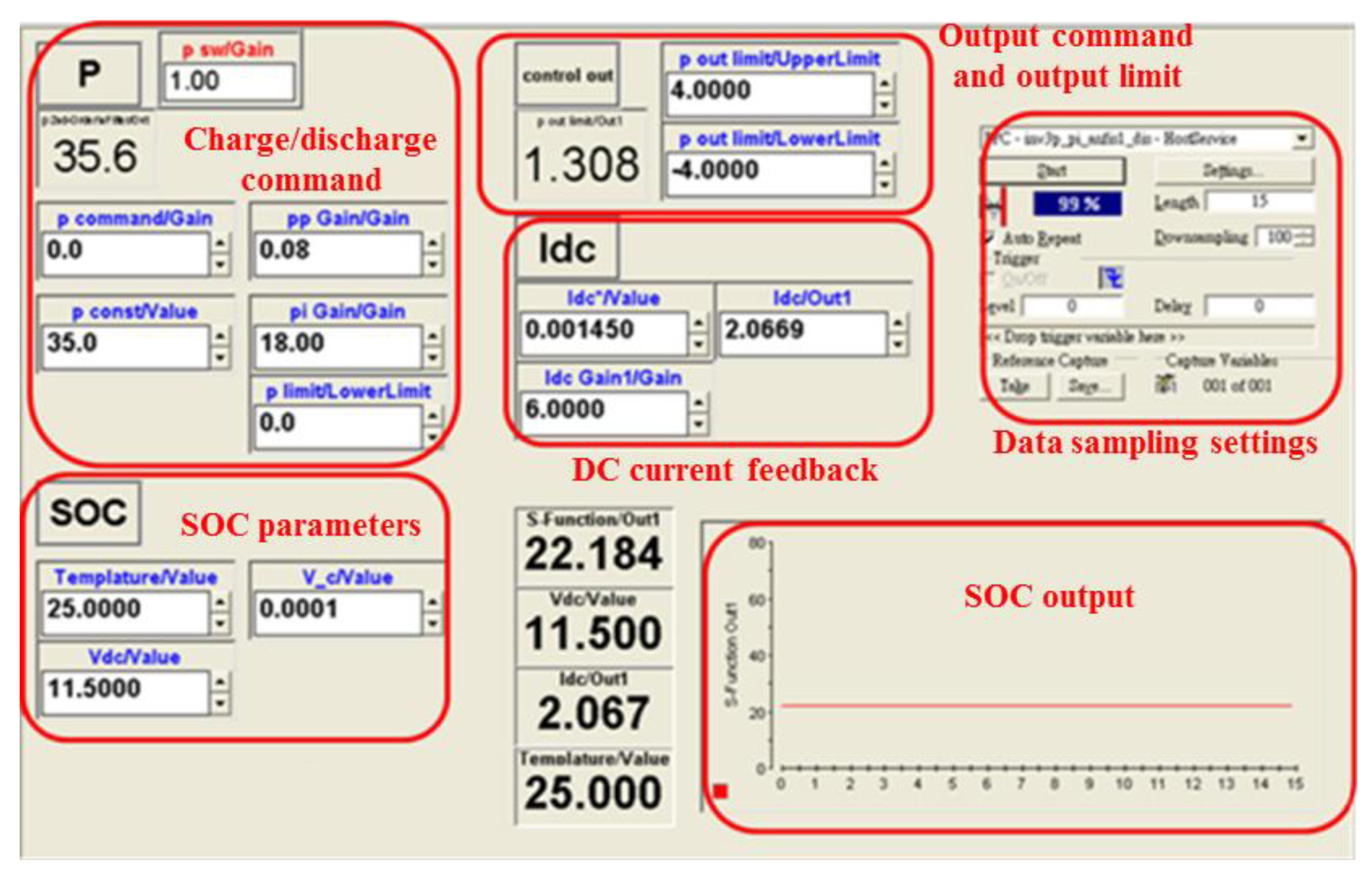
To further test the feasibility of the proposed algorithm, an inverter integrated BESS hardware setup was implemented with dSPACE real-time digital control interface. The DS1104 and dSPACE Real-Time Interface (RTI) interface are used to efficiently perform the arranged charging/discharging cases. RTI is a MATLAB/Simulink graphical interface tool provided by dSPACE, and it makes practical verification of control strategies using dSPACE1104 quite efficient. In addition, its ControlDesk can be used for data measurement, monitoring, and recording. Figure 20 shows a typical ControlDesk interface designed for the hardware implementation of the proposed hybrid real-time SOC estimator.
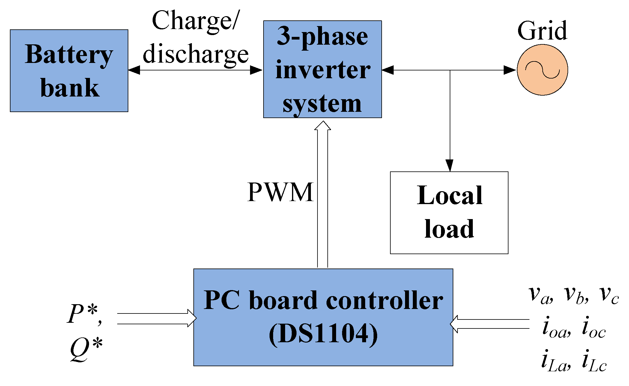
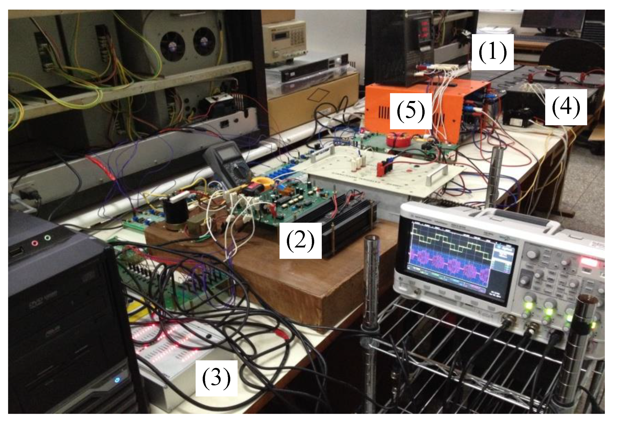
The block diagram of a grid-connected three-phase inverter system with a battery bank is shown in Figure 21, and a photo of the hardware implementation is shown in Figure 22, including (1) battery bank, (2) three-phase inverter, (3) controller (DS1104), (4) local load, and (5) power grid. The control command of the three-phase inverter is equivalent to the charging/discharging power, and the feedback signals include system voltage, inverter output current, and load current. In this experiment, nine identical lead-acid batteries with rated capacities of 14 Ah and voltages of 12 V were connected in series at the DC side of the inverter as the battery bank. The bidirectional three-phase inverter charges/discharges the batteries by adjusting active power command. When discharging, because part of the power is consumed by the local load, a larger AC power command is required to achieve active power feeding to the grid. When charging, because only the power absorbed by the battery bank is considered, the AC power required for charging is close to DC power. With the analog-to-digital (ADC) processing, DS1104 feeds actual line voltage and line current signals back to the computer for the related power calculations.
In this section, three test cases were carried out for verifying the performance of the proposed real-time SOC estimation mechanism: case 1 was for charging operation, case 2 was for discharging operation, and case 3 was for charging/discharging operation. All test cases were performed at room temperature of 25 °C. In case 1 and case 2, SOC was measured at a fixed battery voltage. In case 3, the performance of the proposed ANFIS-based estimation scheme and Coulomb counting were compared through a charge–discharge cycle.
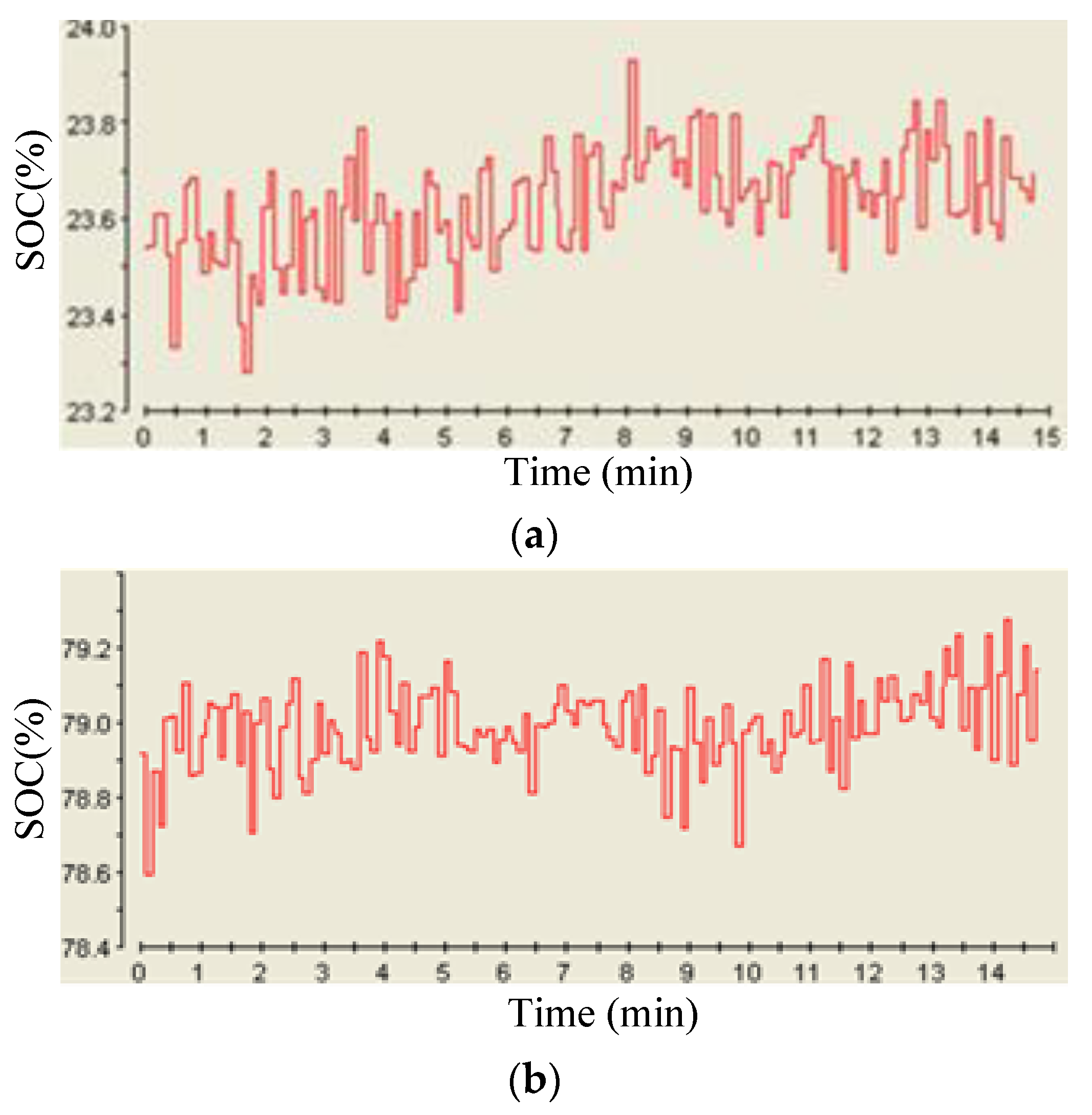
In case 1, charging voltage range was measured between 11.7 V and 14.2 V per single cell, and charging current was 3 A. Measurement was performed at 12.3 V and 13.7 V, respectively. Figure 23 shows SOC estimated by ANFIS algorithm. Less than 2% error was observed, validating the precision of the proposed algorithm. 
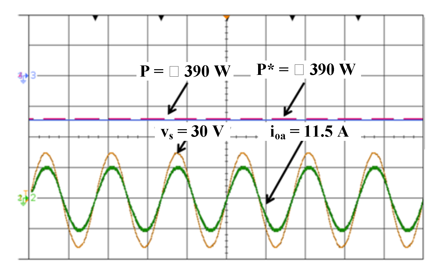
Figure 24 shows the AC active power response during charging operation, including charging power command P* and actual charging power output P, where vs represents system voltage and io represents inverter output line current.
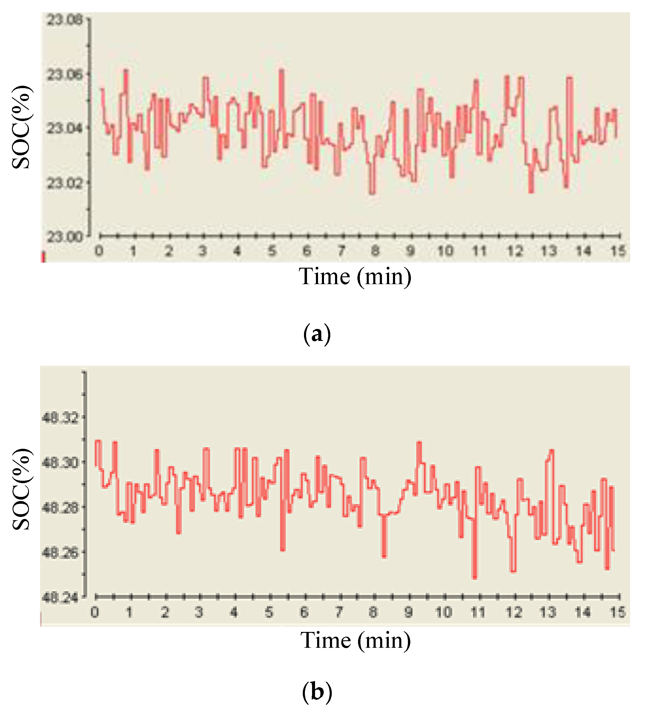
In case 2, the discharging voltage was measured between 10.1 V and 12.7 V per single cell, and discharging current amplitude was the same as that of the charging current in case 1. The measurement was performed at 11.5 V and 11.9 V, respectively. Figure 25 shows the estimated SOC by ANFIS algorithm. 
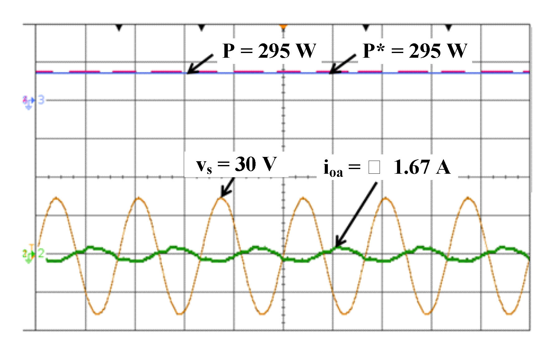
Figure 26 shows the AC active power responding to the discharging operation.
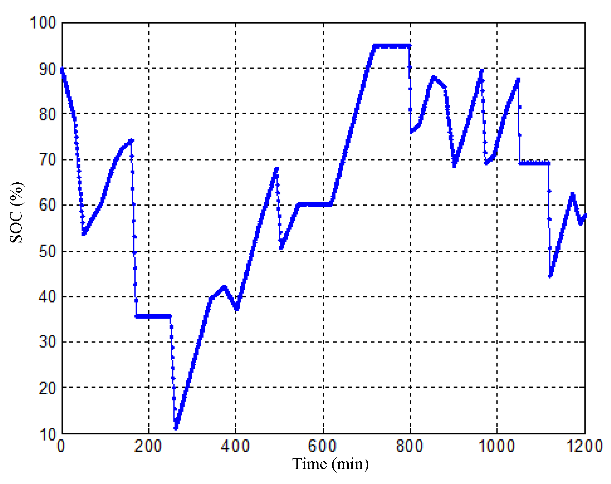
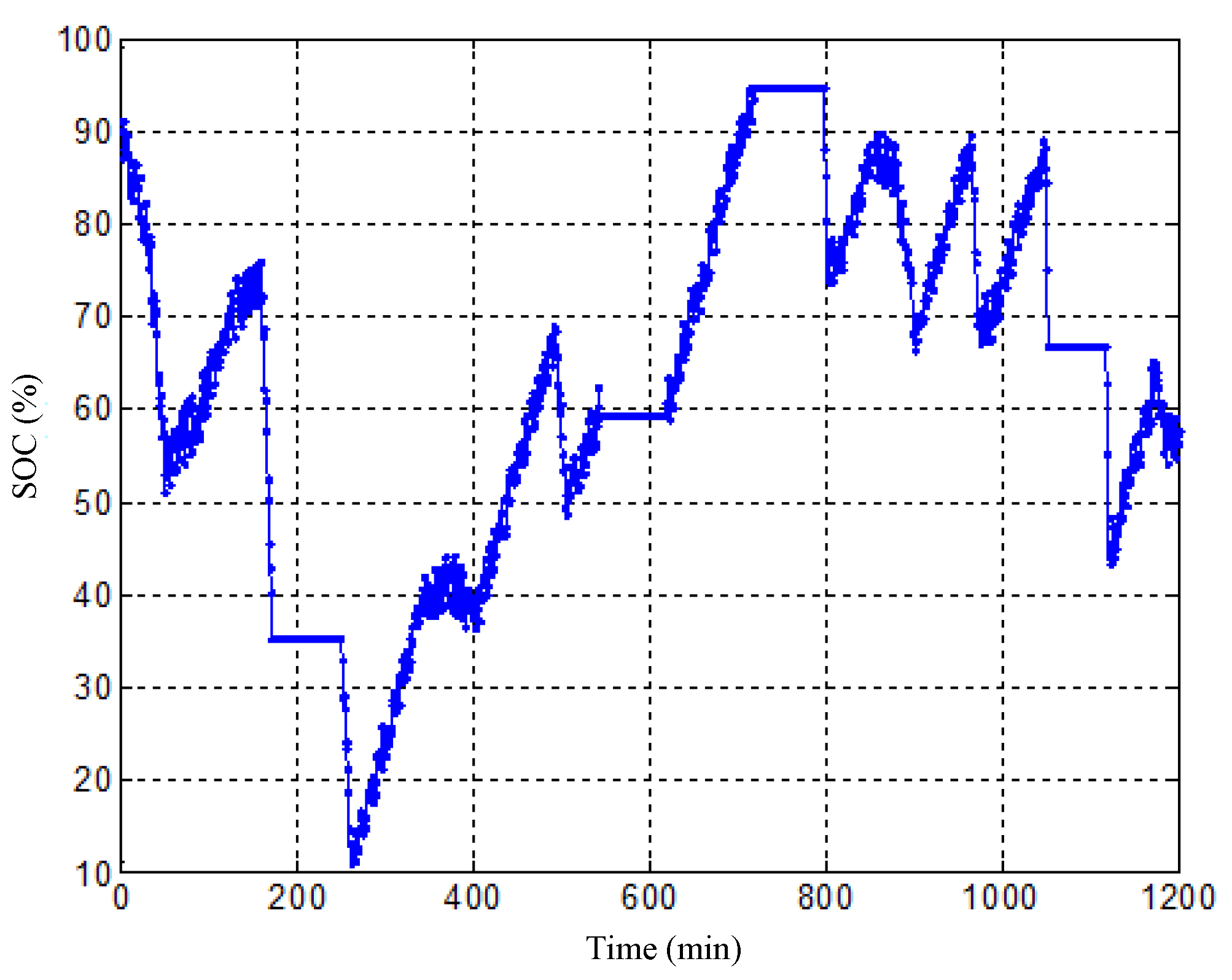
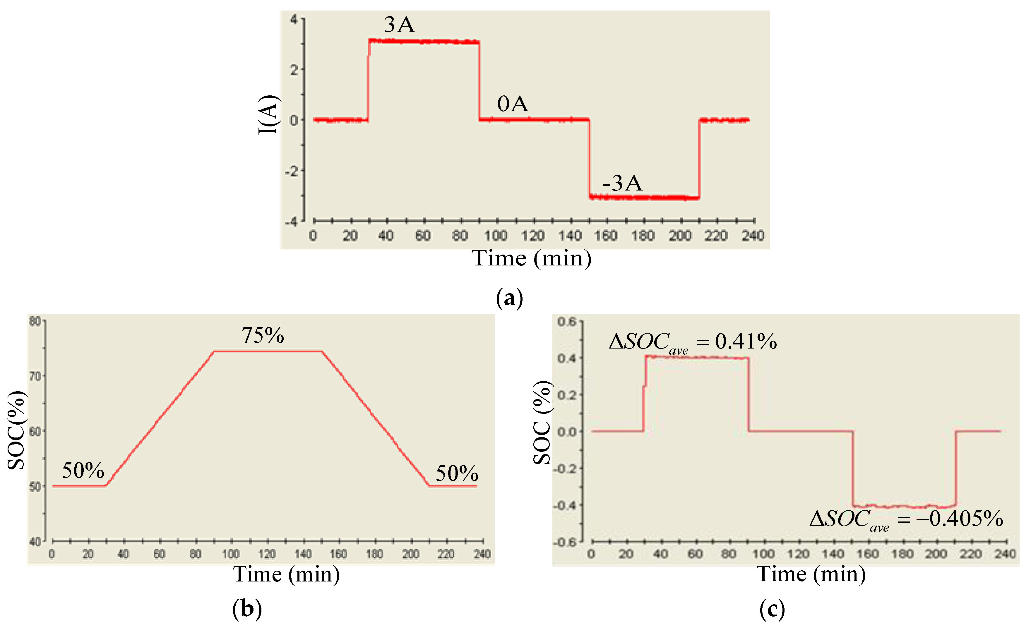
To observe the SOC estimation outputs of the ANFIS real-time SOC estimation scheme and the Coulomb counting method used in the proposed hybrid SOC estimating scheme, in case 3 both the charging and discharging currents were set to be 3 A. The initial SOC was set to 50%. The charging time and discharging time were 1 h each. The battery was firstly set to be charged with a −390 W real power, then rest for 1 h, and then be discharged with a 295 W real power. Figure 27 shows a set of results concerning the battery current and the variation in battery SOC and ΔSOC. As can be seen in Figure 27, a very small (<0.41%) difference between the two methods was observed.

5. Conclusions

In recent years, the BESS has been playing a significant role in various advanced electrical energy management and control applications. An accurate real-time battery’s SOC is technically desirable for achieving the designed BESS control functions; however, there are a number of factors that could affect the SOC of a battery, e.g., the charge and discharge currents, ambient temperature, electrolyte concentration, internal impedance, and the aging level, which is affected by charging and discharging cycles used. In fact, all of these have strongly squeezed the feasibility and performance of existing methods. To ensure the feasibility of SOC-detecting algorithms in practical applications, this paper has proposed a hybrid real-time SOC estimation scheme, and the lead-acid batteries were chosen for the required tests. In this paper, the existing SOC estimation methods reported in open literature have been reviewed and their advantages and drawbacks have been discussed. The design concept, theoretical basis, and implementation procedure of the proposed hybrid estimating scheme have been clearly addressed. In the proposed scheme, ANFIS is used to effectively learn the nonlinear mapping relationships among the SOC and characteristic parameters of a working battery. An adaptive Coulomb counting algorithm is simultaneously used to produce real-time estimated SOC values for double checking the correctness of the SOC estimation of ANFIS. It can be expected that the proposed hybrid SOC-detecting scheme with parallel estimating mechanisms and multiple SOC results can effectively increase the reliability of SOC monitoring. A set of comprehensive simulation and experimental studies have been carried out. Both simulation and typical measured results from an experimental BESS hardware setup demonstrating a maximum of estimated SOC deviation (ΔSOC = 0.41%) have been presented to verify the feasibility and effectiveness of the proposed SOC detection algorithm.

Author Contributions

The corresponding author, C.-T.M. conducted the research work, verified the results, wrote the first draft and polished the final manuscript. All authors have read and agreed to the published version of the manuscript.

Funding

This research was funded by MOST, Taiwan, with grant numbers, MOST 108-2221-E-239-007 and MOST 107-2221-E-239-036 and the APC was funded by MOST 108-2221-E-239-007.

Acknowledgments

The author would like to thank the Ministry of Science and Technology (MOST) of Taiwan for financially support the energy related researches regarding key technologies and the design of advanced power and energy systems.

Conflicts of Interest

The author declares no conflict of interest.

References

  1. Liu, W.; Liu, Y. Energy storage sizing by copula modelling joint distribution for wind farm to be black-start source. IET Renew. Power Gener. 2019, 13, 1882–1890. [Google Scholar] [CrossRef]
  2. Ng, K.S.; Huang, Y.F.; Moo, C.S.; Hsieh, Y.C. An Enhanced Coulomb Counting Method for Estimating State-of-Charge and State-of-Health of Lead-Acid Batteries. In Proceedings of the INTELEC 2009—31st International Telecommunications Energy Conference, Incheon, Korea, 18–22 October 2009. [Google Scholar]
  3. Ng, K.S.; Moo, C.S.; Chen, Y.P.; Hsieh, Y.C. Enhanced coulomb counting method for estimating state-of-charge and state-of-health of lithium-ion batteries. Appl. Energy 2009, 86, 1506–1511. [Google Scholar] [CrossRef]
  4. He, L.; Guo, D. An Improved Coulomb Counting Approach Based on Numerical Iteration for SOC Estimation With Real-Time Error Correction Ability. IEEE Access 2019, 7, 74274–74282. [Google Scholar] [CrossRef]
  5. Chun, C.Y.; Seo, G.S.; Yoon, S.H.; Cho, B.H. State-of-charge estimation for lithium-ion battery pack using reconstructed open-circuit-voltage curve. In Proceedings of the 2014 International Power Electronics Conference (IPEC-Hiroshima 2014—ECCE ASIA), Hiroshima, Japan, 18–21 May 2014. [Google Scholar]
  6. Coroban, V.; Boldea, I.; Blaabjerg, F. A Novel On-line State-of-Charge Estimation Algorithm for Valve Regulated Lead-Acid Batteries used in Hybrid Electric Vehicles. In Proceedings of the 2007 International Aegean Conference on Electrical Machines and Power Electronics, Bodrum, Turkey, 10–12 September 2007. [Google Scholar]
  7. Codecà, F.; Savaresi, S.M.; Manzoni, V. The mix estimation algorithm for battery state-of-charge estimator—Analysis of the sensitivity to measurement errors. In Proceedings of the 48h IEEE Conference on Decision and Control (CDC) Held Jointly with 2009 28th Chinese Control Conference, Shanghai, China, 15–18 December 2009. [Google Scholar]
  8. Sato, S.; Kawamura, A. A new estimation method of state of charge using terminal voltage and internal resistance for lead acid battery. In Proceedings of the Power Conversion Conference-Osaka 2002 (Cat. No.02TH8579), Osaka, Japan, 2–5 April 2002. [Google Scholar]
  9. Piller, S.; Perrin, M.; Jossen, A. Methods for state-of-charge determination and their applications. J. Power Sources 2001, 96, 113–120. [Google Scholar] [CrossRef]
  10. Wu, X.; Solgaard, O. Short-cavity multimode fiber-tip Fabry-Pérot sensors. Opt. Express 2013, 21, 14487–14499. [Google Scholar] [CrossRef] [PubMed]
  11. Aylor, J.H.; Thieme, A.; Johnso, B.W. A battery state-of-charge indicator for electric wheelchairs. IEEE Trans. Ind. Electron. 1992, 39, 398–409. [Google Scholar] [CrossRef]
  12. Ran, L.; Junfeng, W.; Haiying, W.; Gechen, L. Prediction of state of charge of Lithium-ion rechargeable battery with electrochemical impedance spectroscopy theory. In Proceedings of the 2010 5th IEEE Conference on Industrial Electronics and Applications, Taichung, Taiwan, 15–17 June 2010. [Google Scholar]
  13. Zhou, D.; Ravey, A.; Gao, F.; Paire, D.; Miraoui, A.; Zhang, K. Online estimation of state of charge of Li-ion battery using an iterated extended Kalman particle filter. In Proceedings of the 2015 IEEE Transportation Electrification Conference and Expo (ITEC), Dearborn, MI, USA, 14–17 June 2015. [Google Scholar]
  14. Chen, Z.; Xia, B.; Mi, C.C. A novel state-of-charge estimation method for lithium-ion battery pack of electric vehicles. In Proceedings of the 2015 IEEE Transportation Electrification Conference and Expo (ITEC), Dearborn, MI, USA, 14–17 June 2015. [Google Scholar]
  15. He, W.; Williard, N.; Chen, C.; Pecht, M. State of charge estimation for electric vehicle batteries using unscented kalman filtering. Microelectron. Reliab. 2013, 53, 840–847. [Google Scholar] [CrossRef]
  16. Liu, G.; Xu, C.; Jiang, K.; Wang, K. State of charge and model parameters estimation of liquid metal batteries based on adaptive unscented Kalman filter. Energy Procedia 2019, 158, 4477–4482. [Google Scholar] [CrossRef]
  17. Samadi, M.F.; Alavi, S.M.M.; Saif, M. An electrochemical model-based particle filter approach for Lithium-ion battery estimation. In Proceedings of the 2012 IEEE 51st IEEE Conference on Decision and Control (CDC), Maui, HI, USA, 10–13 December 2012. [Google Scholar]
  18. Liu, Q.; Liu, S.; Liu, H.; Qi, H.; Ma, C.; Zhao, L. Evaluation of LFP Battery SOC Estimation Using Auxiliary Particle Filter. Energies 2019, 12, 2041. [Google Scholar] [CrossRef] [Green Version]
  19. Samadi, M.F.; Alavi, S.M.M.; Saif, M. Online state and parameter estimation of the Li-ion battery in a Bayesian framework. In Proceedings of the 2013 American Control Conference, Washington, DC, USA, 17–19 June 2013. [Google Scholar]
  20. Hou, J.; He, H.; Yang, Y.; Gao, T.; Zhang, Y. A Variational Bayesian and Huber-Based Robust Square Root Cubature Kalman Filter for Lithium-Ion Battery State of Charge Estimation. Energies 2019, 12, 1717. [Google Scholar] [CrossRef] [Green Version]
  21. Yin, C.; Zhong, Q.; Chen, Y.; Zhong, S. Estimating the state of charge of lithium batteries based on fractional-order sliding-mode observer. In Proceedings of the ICFDA’14 International Conference on Fractional Differentiation and Its Applications 2014, Catania, Italy, 23–25 June 2014. [Google Scholar]
  22. Mao, J.; Zhao, L.; Lin, Y. State-of-charge estimation of lithium-ion polymer battery based on sliding mode observer. In Proceedings of the 33rd Chinese Control Conference, Nanjing, China, 28–30 July 2014. [Google Scholar]
  23. Dey, S.; Ayalew, B.; Pisu, P. Nonlinear Robust Observers for State-of-Charge Estimation of Lithium-Ion Cells Based on a Reduced Electrochemical Model. IEEE Trans. Control Syst. Technol. 2015, 23, 1935–1942. [Google Scholar] [CrossRef]
  24. Tian, Y.; Li, D.; Tian, J.; Xia, B. State of charge estimation of lithium-ion batteries using an optimal adaptive gain nonlinear observer. Electrochim. Acta 2017, 225, 225–234. [Google Scholar] [CrossRef]
  25. Lee, S.; Kim, J. Discrete wavelet transform-based denoising technique for advanced state-of-charge estimator of a lithium-ion battery in electric vehicles. Energy 2015, 83, 462–473. [Google Scholar] [CrossRef]
  26. Xia, B.; Cui, D.; Sun, Z.; Lao, Z.; Zhang, R.; Wang, W.; Sun, W.; Lai, Y.; Wang, M. State of charge estimation of lithium-ion batteries using optimized Levenberg-Marquardt wavelet neural network. Energy 2018, 153, 694–705. [Google Scholar] [CrossRef]
  27. Alfi, A.; Charkhgard, M.; Zarif, M.H. Hybrid state of charge estimation for lithium-ion batteries: Design and implementation. IET Power Electron. 2014, 7, 2758–2764. [Google Scholar] [CrossRef]
  28. Zhang, F.; Liu, G.; Fang, L.; Wang, H. Estimation of Battery State of Charge With H∞ Observer: Applied to a Robot for Inspecting Power Transmission Lines. IEEE Trans. Ind. Electron. 2012, 59, 1086–1095. [Google Scholar] [CrossRef]
  29. Charkhgard, M.; Zarif, M.H. Design of adaptive H∞ filter for implementing on state-of-charge estimation based on battery state-of-charge-varying modelling. IET Power Electron. 2015, 8, 1825–1833. [Google Scholar] [CrossRef]
  30. Husnayain, F.; Utomo, A.R.; Priambodo, P.S. State of charge estimation for a lead-acid battery using backpropagation neural network method. In Proceedings of the 2014 International Conference on Electrical Engineering and Computer Science (ICEECS), Kuta, Indonesia, 24–25 November 2014. [Google Scholar]
  31. Hussein, A.A. Derivation and Comparison of Open-loop and Closed-loop Neural Network Battery State-of-Charge Estimators. Energy Procedia 2015, 75, 1856–1861. [Google Scholar] [CrossRef] [Green Version]
  32. Zhou, F.; Wang, L.; Lin, H.; Lv, Z. High accuracy state-of-charge online estimation of EV/HEV lithium batteries based on Adaptive Wavelet Neural Network. In Proceedings of the 2013 IEEE ECCE Asia Downunder, Melbourne, VIC, Australia, 3–6 June 2013. [Google Scholar]
  33. Singh, P.; Vinjamuri, R.; Wang, X.; Reisner, D. Design and implementation of a fuzzy logic-based state-of-charge meter for Li-ion batteries used in portable defibrillators. J. Power Sources 2006, 162, 829–836. [Google Scholar] [CrossRef]
  34. Zenati, A.; Desprez, P.; Razik, H.; Rael, S. Impedance measurements combined with the fuzzy logic methodology to assess the SOC and SOH of lithium-ion cells. In Proceedings of the 2010 IEEE Vehicle Power and Propulsion Conference, Lille, France, 1–3 September 2010. [Google Scholar]
  35. Hametner, C.; Jakubek, S. Fuzzy observer design for local model network based battery state of charge estimation. In Proceedings of the 21st Mediterranean Conference on Control and Automation, Chania, Greece, 25–28 June 2013. [Google Scholar]
  36. Hansen, T.; Wang, C.J. Support vector based battery state of charge estimator. J. Power Sources 2005, 141, 351–358. [Google Scholar] [CrossRef]
  37. Jansen, P.; Vollnhals, M.; Renner, D.; Vergossen, D.; John, W.; Götze, J. Advanced binary search pattern for impedance spectra classification for determining the state of charge of a lithium iron phosphate cell using a support vector machine. Adv. Radio Sci. 2016, 14, 55–62. [Google Scholar] [CrossRef] [Green Version]
  38. Ismail, M.M.; Hassan, M.A.M. The state of charge estimation for rechargeable batteries based on artificial neural network techniques. In Proceedings of the 2013 International Conference on Control, Decision and Information Technologies (CoDIT), Hammamet, Tunisia, 6–8 May 2013. [Google Scholar]
  39. Fekry, H.M.; Hassan, M.A.M.; Abd El Aziz, M.M. The state of charge estimation for rechargeable batteries using Adaptive Neuro Fuzzy Inference System (ANFIS). In Proceedings of the 2012 First International Conference on Innovative Engineering Systems, Alexandria, Egypt, 7–9 December 2012. [Google Scholar]
  40. Cai, C.H.; Du, D.; Liu, Z.Y. Battery state-of-charge (SOC) estimation using adaptive neuro-fuzzy inference system (ANFIS). In Proceedings of the 12th IEEE International Conference on Fuzzy Systems, FUZZ ‘03, St Louis, MO, USA, 25–28 May 2003. [Google Scholar]
  41. Lin, H.T.; Liang, T.J. Prediction of state of charge for Li-Co batteries with fuzzy inference system based fuzzy neural networks. In Proceedings of the 2013 1st International Future Energy Electronics Conference (IFEEC), Tainan, Taiwan, 3–6 November 2013. [Google Scholar]
  42. YUASA. Available online: http://www.yuasa.com.tw/ (accessed on 25 November 2019).
Figure 1. System block diagram of the proposed hybrid SOC estimation scheme.
Processes 08 00002 g001
Figure 2. Battery SOC voltage curves: (a) charge curve; (b) discharge curve.
Processes 08 00002 g002
Figure 3. System configuration of the proposed adaptive network-based fuzzy inference system (ANFIS).
Processes 08 00002 g003
Figure 4. System block diagram of the proposed SOC estimation scheme.
Processes 08 00002 g004
Figure 5. System configuration of the proposed ANFIS.
Processes 08 00002 g005
Figure 6. Block diagram of the experimental measurement system.
Processes 08 00002 g006
Figure 7. Photo of the experimental measurement system.
Processes 08 00002 g007
Figure 8. Experimental results of capacity measurement at: (a) various discharging currents at 25 °C; (b) 0.1C discharging current with various temperatures; (c) various charging currents at 25 °C; (d) 0.1C charging current with various temperatures.
Processes 08 00002 g008
Figure 9. Charging training data of set A at 25 °C.
Processes 08 00002 g009
Figure 10. Discharging training data of set B at 25 °C.
Processes 08 00002 g010
Figure 11. Training data for the charging efficiency adjusting factor (K).
Processes 08 00002 g011
Figure 12. Training data for the discharging efficiency adjusting factor (K).
Processes 08 00002 g012
Figure 13. ANFIS SOC estimation results during charging at 25 °C: (a) results; (b) error.
Processes 08 00002 g013
Figure 14. Testing of ANFIS SOC estimation results during discharging at 25 °C: (a) results; (b) error.
Processes 08 00002 g014
Figure 15. The designed simulation system for the proposed SOC estimating scheme.
Processes 08 00002 g015
Figure 16. The real-time calculation of voltage slew rate.
Processes 08 00002 g016
Figure 17. The estimation result of efficiency adjusting factor.
Processes 08 00002 g017
Figure 18. The SOC estimation result of Coulomb counting.
Processes 08 00002 g018
Figure 19. The SOC estimation result of ANFIS.
Processes 08 00002 g019
Figure 20. The hardware implementation of the proposed hybrid real-time SOC estimator.
Processes 08 00002 g020
Figure 21. Block diagram of the hardware implementation.
Processes 08 00002 g021
Figure 22. Photo of the experimental hardware implementation.
Processes 08 00002 g022
Figure 23. SOC estimated by ANFIS algorithm at charging current of 3 A and voltages of (a) 12.3 V; (b) 13.7 V.
Processes 08 00002 g023
Figure 24. The inverter active power, voltage, and current waveforms (phase-a) on the grid side corresponding to a 3A charging current. (t: 10 ms/div).
Processes 08 00002 g024
Figure 25. SOC estimated by ANFIS algorithm at discharging current of 3 A and voltages of (a) 11.5 V; (b) 11.9 V.
Processes 08 00002 g025
Figure 26. The inverter active power, voltage and current waveforms (phase-a) on the grid side corresponding to a 3A discharging current. (t: 10 ms/div).
Processes 08 00002 g026
Figure 27. Measured results in case 3: (a) battery current; (b) variations in battery SOC; (c) ΔSOC.
Processes 08 00002 g027
Table 1. Summary of conventional state of charge (SOC)-detecting methods.
MethodAdvantagesDisadvantages
Coulomb counting1. Simple implementation and modification1. Requires initial SOC value
2. Widely applicable2.Accumulated errors
OCV1. Simple implementation1. Requires open circuit
2. Relatively precise2. Requires resting before measuring
Internal resistance1. Simple implementation1. Requires high-precision equipment
2. Can easily generate error
On-load voltage1. Simple implementation1. Requires high-precision equipment
2. Applicable during charging/discharging2. Can easily generate error
Electrolyte concentration1. Relatively precise1. Requires resting before measuring
2. Requires access to electrolyte
EIS1. Relatively precise1. Easily interfered by ripple/harmonics
2. Requires costly equipment
Table 2. Discharging experiment arrangement.
Discharging Rate (C)Current (A)Cutoff Voltage (V)
0.050.6510.6
0.11.310.5
0.22.610.3
0.45.210
0.67.89.7
0.810.49.4
1139.2
1.519.58.8
2268.2
2.532.57.9
Table 3. Charging experiment arrangement.
Charging Rate (C)Current (A)Cutoff Voltage (V)
25 °C30 °C35 °C40 °C
0.050.6514.414.2814.1614.04
0.11.314.414.2814.1614.04
0.151.9514.414.2814.1614.04
0.22.614.414.2814.1614.04
0.253.2514.414.2814.1614.04
Table 4. Battery discharging capacities.
Discharging Rate (C)Current (A)Capacity (Ah)
25 °C30 °C35 °C40 °C
0.050.6512.516212.534012.657912.7725
0.11.312.232612.258412.384812.5043
0.22.611.383211.541111.697811.8489
0.45.210.394910.555210.741610.9155
0.67.89.965110.136810.365710.5763
0.810.49.42159.60639.883510.1355
1139.02629.23169.57419.8826
1.519.58.27278.57518.93499.2654
2267.99038.42298.82679.2049
2.532.57.53267.96808.38398.7863
Table 5. Battery charging capacities.
Charging Rate (C)Current (A)Capacity (Ah)
25 °C30 °C35 °C40 °C
0.050.6512.780612.785712.793612.8037
0.11.312.513812.554712.577912.5986
0.151.9511.987512.080612.127812.1756
0.22.611.583011.731611.804411.8810
0.253.2510.605110.745710.823110.9005
Table 6. Amount of training and testing data for SOC estimation algorithm.
Amount of Training DataAmount of Testing Data
ChargeDischargeChargeDischarge
Set A102216723872146860
Set B3926563935147877
Table 7. Training result of ANFIS SOC estimation during charging.
Number of Membership Function NodesNumber of RulesRMSE (%)Max. RMSE (%)
VITΔV
Set A4432960.08620.3796
4332720.10370.4197
4322480.19730.7756
3322360.22860.9391
Set B4332720.11100.4456
4322480.20870.8246
3322360.23500.9750
Table 8. Training result of ANFIS SOC estimation during discharging.
Number of Membership Function NodesNumber of RulesRMSE (%)Max. RMSE (%)
VITΔV
Set A65422400.06160.5503
45421600.10360.6886
65411200.06150.5472
4541800.10370.6878
Set B55444000.09500.5989
45421600.11450.7504

