Article

Enhancement Effect of Ordered Hierarchical Pore Configuration on SO2 Adsorption and Desorption Process

1
School of Energy and Safety Engineering, Tianjin Chengjian University, Tianjin 300384, China
2
School of Science and Technology, Tianjin University, Tianjin 300072, China
*
Author to whom correspondence should be addressed.
Processes 2019, 7(3), 173; https://doi.org/10.3390/pr7030173
Submission received: 28 February 2019 / Revised: 18 March 2019 / Accepted: 19 March 2019 / Published: 25 March 2019
(This article belongs to the Special Issue Energy, Economic and Environment for Industrial Production Processes)

Abstract

:
Carbonaceous adsorbents with both high sulfur capacity and easy regeneration are required for flue gas desulfurization. A hierarchical structure is desirable for SO2 removal, since the micropores are beneficial for SO2 adsorption, while the mesopore networks facilitate gas diffusion and end-product H2SO4 storage. Herein, an ordered hierarchical porous carbon was synthesized via a soft-template method and subsequent activation, used in SO2 removal, and compared with coal-based activated carbon, which also had a hierarchical pore configuration. The more detailed, abundant micropores created in CO2 activation, especially the ultramicropores (d < 0.7 nm), are essential in enhancing the SO2 adsorption and the reserves rather than the pore patterns. While O2 and H2O participate in the reaction, the hierarchical porous carbon with ordered mesopores greatly improves SO2 removal dynamics and sulfur capacity, as this interconnecting pore pattern facilitates H2SO4 transport from micropores to mesopores, releasing the SO2 adsorption space. Additionally, the water-washing regeneration performances of the two types of adsorbents were comparatively determined and provide a new insight into the mass-transfer resistance in the pore structure. The ordered hierarchical carbon promoted H2SO4 desorption efficiency and cycled SO2 adsorption–desorption performance, further indicating that interconnecting micro- and mesopores facilitated the diffusion of adsorbates.

1. Introduction

Along with the rapid development of the economy in China, a large amount of SO2 emissions due to coal consumption in primary energy has resulted in severe air pollution [1,2]. The continued increase in coal consumption and utilization of high-sulfur coal will lead to more severe SO2 pollution. Over recent decades, China has invested enormously in limestone–gypsum wet flue gas desulfurization (WFGD). However, this technology faces the dilemma of large water consumption levels, low market value byproducts, secondary pollution, and CO2 escape [3]. Porous carbons, including activated carbon [4,5], activated coke [6,7,8] and semicoke [9,10], have been assessed to remove SO2 from flue gas based on their abundant pore structures and specific chemical functionality, in addition to their advantages of water conservation, diversified sulfur resource recovery, adsorbent cyclic utilization, and reduced environmental impact. The current porous carbons used in flue gas desulfurization are mainly micro- and mesopore hierarchical coal-based activated carbons with Brunauer–Emmett–Teller (BET) surface areas of 650–850 m2·g−1. However, the major drawbacks of activated carbons are their low sulfur capacity and costly regeneration, which has hindered their applications at a large scale in China [11,12].
As reported in the literature [13,14], the presence of O2 and H2O in flue gas causes the oxidation of absorbed SO2, leading to the formation of H2SO4. Sun et al. [7] have demonstrated this process in a commercial activated coke with hierarchical pore configuration (BET surface area of 948 m2·g−1, micropore volume of 0.32 cm3·g−1, and mesopore volume of 0.11 cm3·g−1) to achieve optimal removal rate and high sulfur capacity. The end-product H2SO4 was found to form in micropores that could migrate to mesopores, which guarantees the continuous proceeding of the SO2 adsorption. Therefore, an ideal adsorbent should possess a hierarchical structure, in which the micropores will provide high adsorption and catalytic oxidation capacity, while the mesopores promote gas diffusion and end-product storage [15,16]. To enhance SO2 removal performance, Karatepe et al. [17] investigated the influence of pore parameters on SO2 adsorption and found that the micropore volume of the activated carbons, rather than the BET surface area, played an important role in SO2 adsorption. Wang et al. [18] discussed the effect of the pore width on the SO2 micropore filling mechanism. Mangun et al. [19] used activated carbon fibers as adsorbents for SO2, since they have a uniform micropore structure and faster adsorption kinetics as compared to activated carbons. Moreover, Bagreev et al. [20] investigated the role of nitrogen functionality in the process of SO2 adsorption and found that quaternary and pyridinic-type nitrogen significantly enhanced the adsorption capacity. On top of the above-mentioned research, previous studies have focused on improving pore volumes and surface areas, tuning pore structures and pore sizes, or adding catalysts [21,22]. However, hierarchical pore structures remain challenging for synthesis and application in flue gas desulfurization. Furthermore, hierarchical materials are also promising in many applications, including water and air purification [23], gas separation [24], catalysis [25], chromatography [26], and energy storage [27]. Related research results are worth learning about for hierarchical pore structures used in flue gas desulfurization.
Although common coal-based activated carbon can be prepared to possess hierarchical structures, the unconnected micro- and mesoporous structures caused by the complex structures of raw materials may hinder the diffusion of gas and the migration of adsorbates. Our strategy is to prepare an ordered hierarchical pore structure via a soft-template method to promote the synthesis of ordered mesopores and subsequent activation toward the development of abundant micropores embedded in the mesopore walls. These adsorbents with ordered mesoporous features were used for SO2 removal and compared with coal-based activated carbons. We focused on the effects of pore sizes and pore patterns on the SO2 removal process, including SO2 separate adsorption and reaction with O2 and H2O participation. The sulfur-containing adsorbate storage spaces within adsorbents under various conditions were further determined. Furthermore, to better examine the diffusivity of the ordered hierarchical structure, the water-washing regeneration efficiency and the cycled desulfurization–regeneration performance of the two adsorbents were comparatively investigated.

2. Materials and Methods

2.1. Preparation of Coal-Based Activated Carbon

A series of coal-based activated carbons (ACs) were prepared using Taixi anthracite (Ningxia, China) as a precursor. The AC samples were prepared through carbonization and subsequent CO2 activation. In brief, 10 g of feed coal (size range of 0.25–0.38 mm) was placed in a quartz tubular reactor (23 mm inner diameter and 400 mm length) located in a horizontal furnace. Carbonization was carried out by heating to 973 K at a rate of 8 K·min−1 under a N2 (99.999%) flow of 350 mL·min−1 and maintained for 40 min. Then, the reactor was heated to 1123 K in a CO2 (99.999%) constant flow of 350 mL·min−1 for various times to obtain various burn-offs ranging from 12.8% to 71.3%. The burn-off, related to the activation step, is the ratio between the weight of fixed carbon reacted and the initial char weight [28,29]. The notations used for the coal-based activated carbons are AC-C-(burn-off).

2.2. Synthesis of Ordered Mesoporous Carbon and Hierarchical Carbon

The ordered mesoporous carbons (OMCs) were prepared via co-assembly of the phenolic resin precursor with a triblock copolymer Pluronic F127 via soft templating. The phenolic resin precursor was synthesized as follows: 40 g of phenol was heated at 318 K in a water bath until completely melted. Then, 20% NaOH solution (34 mL) was added to the conical flask containing the melted phenol in drops, and the mixture was stirred for 15 min. Then, a 37% formaldehyde solution was added to the mixture in drops with stirring. Note that the formaldehyde and phenol were mixed at a substance ratio of 3:1. Subsequently, the conical flask was submerged in a water bath set at 358 K with continuous stirring for 1 h and then cooled to room temperature. The pH value of the resulting mixture was adjusted to 7.0 with 20% hydrochloric acid solution and then the water was removed using a rotary evaporator at 323 K for 4 h to obtain the dried phenolic resin. A 15% phenolic resin-ethanol solution was prepared for use. Triblock copolymer Pluronic F127 was used as the soft template for the synthesis of mesoporous carbons. 3 g of F127 was dispersed in ethanol to prepare the 17% F127-ethanol solution, which was then added to a 15% phenolic resin–ethanol solution with continuous stirring for 30 min. The resultant solution was allowed to sit without stirring at room temperature until the ethanol was volatilized completely; it was subsequently heated at 373 K for 24 h to obtain the polymer composite. The resultant polymer composite was heated to 1123 K at a ramp rate of 1 K·min−1 and held for 3 h in a N2 (99.999%) flow of 350 mL·min−1 in the horizontal furnace to slowly decompose the surfactant F127 and produce the mesoporous carbon.
To further improve the textural properties, a subsequent CO2 activation was carried out at 1123 K in in the horizontal furnace as mentioned above in a CO2 (99.999%) constant flow of 350 mL·min−1 for various times to obtain various burn-offs, denoted as OMC-C-(burn-off).
Except for Pluronic F127 (Sigma-Aldrich, Missouri, USA), all other chemicals used in the synthesis of the adsorbents were obtained from Kemiou, Tianjin, China.

2.3. Characterizations

Pore parameters of ACs and OMCs were determined by N2 adsorption over a relative pressure P/P0 range from 10−7 to 1 at 77 K using an automatic apparatus (ASAP 2020, Micromeritics, Norcross, GA, USA). Before this analysis, the sample was degassed under vacuum at 473 K for 10 h. Note that the degassing step was terminated when the saturated adsorbent was measured to avoid the desorption of the adsorbates (i.e., SO2, SO3, H2SO4) [30]. The BET surface area was calculated from the isotherm using the Brunauer–Emmett–Teller (BET) equation. The micropore surface was calculated by the t-plot method [31]. The micropore volume and differential pore volume were estimated by the Horvath–Kawazoe (HK) method [17]. The mesopore volume and pore size distributions of the samples were calculated by applying the Barrett–Joyner and Halenda (BJH) method [32].
The microstructural morphology of ACs and OMCs was analyzed using transmission electron microscopy (TEM, Tecnai T20, FEI, Hillsboro, OR, USA). The small angle X-ray scattering (SAXS) patterns (0.5° < 2θ < 5°) were acquired on a D/max 2400X diffractometer operating at 40 KV and 100 mA using Cu Kα radiation (λ = 1.5406 Å, Rigaku, Tokyo, Japan). Elemental analysis (EA) was performed using an analyzer (Vario MACRO cube, Elementar, Langenselbold, Germany) for determination of the total carbon and oxygen content of the bulk samples. The types of surface functional groups were identified by Fourier transform infrared (FTIR) spectroscopy (Magna-IR 560 E.S.P, Nicolet, Madison, WI, USA). The spectrometer was used in the range of 4000–500 cm−1 with a resolution of 4 cm−1, using pressed KBr pellets that contained approximately 0.5 wt.% samples, to realize the measurements.

2.4. SO2 Adsorption Measurements

The SO2 adsorption experiments were carried out in a fixed bed reactor using 2.5 g of sample at 313 K or 353 K. The experimental system consisted of a tubular reactor (20 mm ID) placed in a vertical furnace with a system of valves and mass flow controllers. The mass flow controllers were used to control the flows of SO2, O2, and N2, respectively. The water vapor was introduced by bubbling a flow of N2 at a fixed temperature in water bath. Flow of H2O was controlled by adjusting N2-carrying flow. An online Fourier transform infrared gas analyzer (DX4000, Gasmet, Vantaa, Finland) was used to continuously monitor the SO2, O2, and H2O concentrations of the reactor inlet and outlet. In addition, the experimental installation was provided with a bypass to allow the SO2, O2, and H2O concentrations to be measured before introducing the gas mixture into the reactor. The inlet gas volumetric compositions used in different experiments were 1500 ppm SO2, with or without 5% O2, with or without 10% H2O, with N2 balance, and a total flow rate of 1.2 L·min−1. It is worth mentioning that a previous work found that CO2 in the inlet gas does not influence SO2 removal behavior [33].
SO2 removal efficiency versus time was defined by recording concentrations of SO2 at the inlet and outlet in real time via the gas analyzer. The amount of SO2 removed, expressed in mg SO2 g−1 carbon, was calculated by the integration of SO2 conversion versus time curves.

2.5. Water-Washing Regeneration

Water-washing regeneration, just as its name implies, recovers the saturated adsorbents by extracting adsorbate H2SO4 from the inner pores depending on the H2SO4 differential concentration in water. First, 2.5 g of spent adsorbent was dispersed in 100 mL of water at 298 K with a magnetic stirring bar for an appropriate time ranging from 15 to 75 min. After filtering and subsequent drying at 373 K for 12 h, the regenerate absorbent was obtained and reused in desulfurization.

3. Results

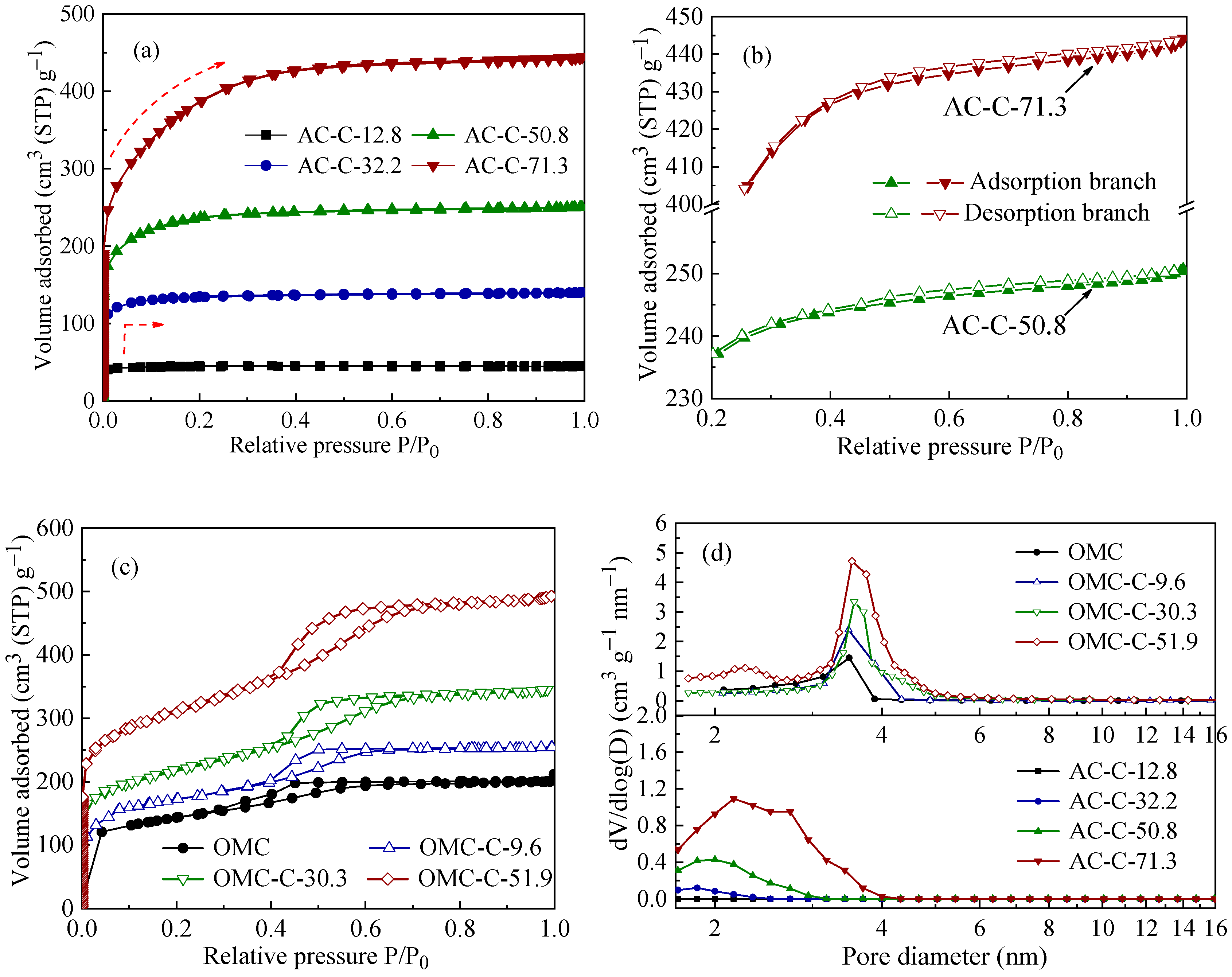
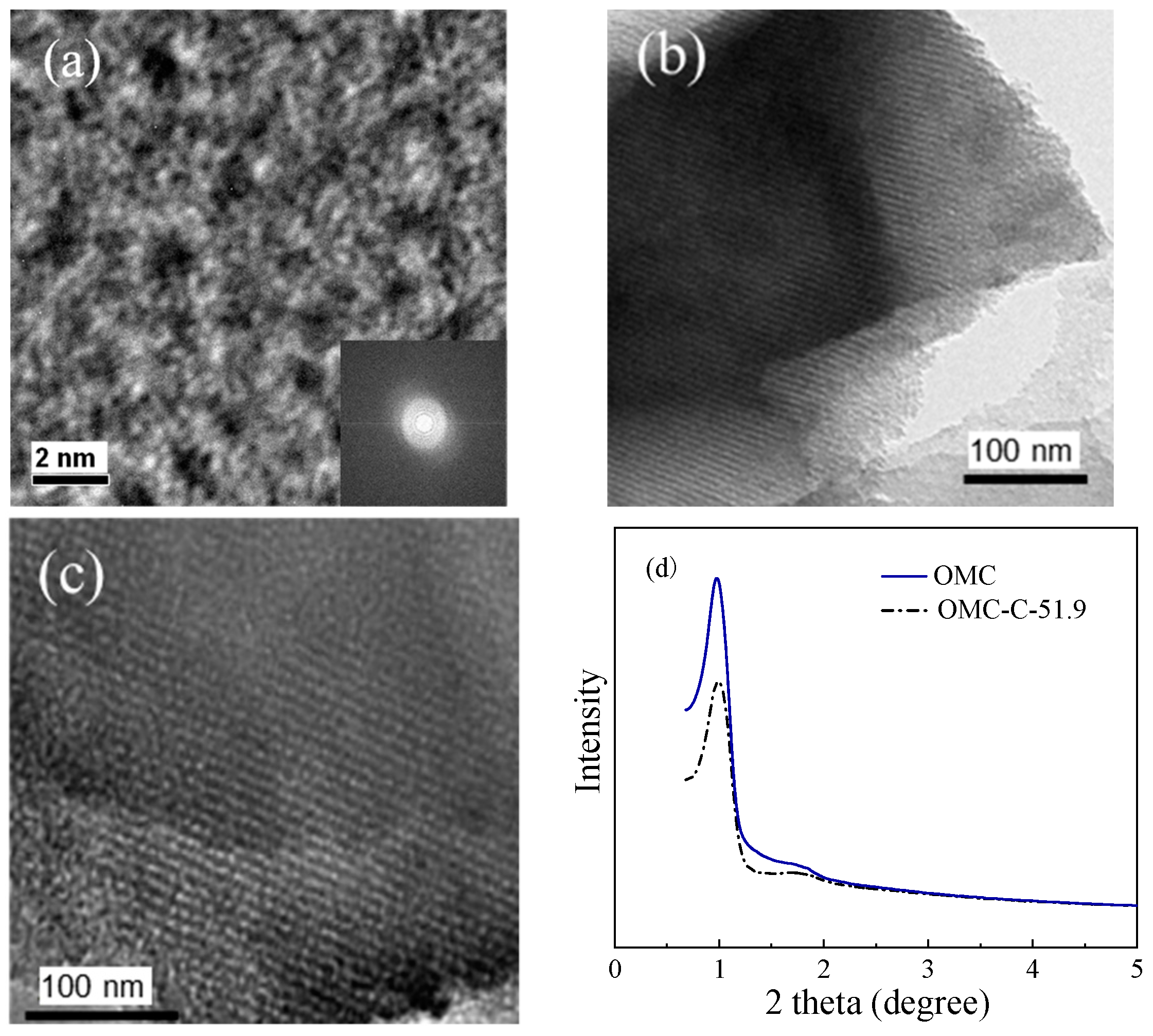
3.1. Structural Characterization of Two Different Carbon Adsorbents

We prepared two species of carbonaceous adsorbents, including coal-based activated carbons with hierarchical pore structures and ordered mesoporous carbons with micropores embedded in the mesopore walls. The nitrogen adsorption–desorption isotherms and the resulting BJH mesopore size distributions of the AC-C-x and OMC-C-x are shown in Figure 1.
The samples of AC-C-12.8 and AC-C-32.2 display a type I adsorption isotherm without any hysteresis loop and significant nitrogen uptake at a relative pressure less than 0.1, indicating the presence of a large fraction of micropores. With an increase in burn-off, the amount of adsorbed nitrogen increases and the knee becomes broader, which indicates the development of micropores. Meanwhile, the hysteresis loop appears, as shown in Figure 1b, indicating the presence of mesopores, and the corresponding BJH mesopore size distributions present a mesopore size in a range from 2–4 nm for AC-C-50.8 and AC-C-71.3, as shown in Figure 1d.
Figure 1c shows that the OMC sample has type IV isotherms with a type H1 hysteresis loop at p/p0 from 0.3 to 0.6, indicating the presence of two-dimensional hexagonal mesoporous structures [34] and the major mesopore distribution centered at 3–4 nm. After CO2 activation, the nitrogen sorption isotherms of the three OMC-C-x samples all show steep uptakes at low relative pressures, indicating the presence of micropores. Compared to untreated OMC, the hysteresis moves to the right to p/p0 > 0.4, suggesting that the ordered mesostructure is well preserved and the mesopore size is widened.
The pore microstructural characteristics of the ACs and OMCs are listed in Table 1. It is clear that with CO2 treatment at 1123 K, higher burn-offs give rise to higher BET surface areas and larger pore volumes (ultramicropore, micropore, and mesopore volumes). The activation with CO2 clearly creates new micropores and expands the existing porous system. The micro- and mesopores co-existed in the AC-C-50.8, AC-C-71.3, and OMC-C-x samples.
TEM images of AC-C-50.8 and the corresponding Fourier diffractogram are shown in Figure 2a. The TEM image appears to have an isotropic cross-sectional structure, showing a random orientation of the pores. In contrast, Figure 2b shows the presence of a two-dimensional ordered mesoporous structure of the OMC sample. After CO2 activation with 51.9% burn-off, the ordered structure still remains as Figure 2c shows, suggesting that the ordered mesostructure is well preserved under CO2 treatment. The periodicity of OMC-C-51.9 was further confirmed using small-angle XRD, as shown in Figure 2d. The existence of the (100) peaks is clearly observed, which supports the presence of two-dimensional arrays. Thus, micro- and mesoporous hierarchical carbons with ordered mesoporous characteristics were obtained.

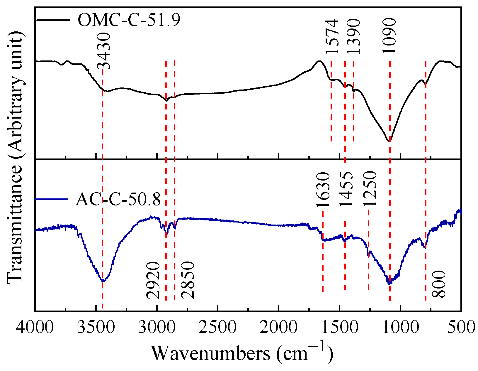
3.2. Chemical Composition of Two Different Carbon Adsorbents

To understand and contrast two species of adsorbent chemical compositions, EA and FTIR analysis were performed. The bulk oxygen content by EA was found to increase from 3.4 wt.% to 6.7 wt.% with increasing burn-off for OMC-C-x, as shown in Table 1. In contrast, the oxygen content of AC-C-x first increases, reaching a maximum when the burn-off is 50.8%, and then decreases with increasing burn-off degree. The decrease in the oxygen content of AC-C-71.3 may be attributed to a significant increase in the ash content, which reaches 10% because of the high burn-off degree.
Generally, the reaction of CO2 with the carbon atoms in porous carbon increases the oxygen content and creates oxygen-containing groups on the surface. The characteristic functional groups of the AC-C-50.8 and OMC-C-51.9 are evaluated by FTIR, as shown in Figure 3. Both spectra have similar absorption bands, being slightly different in some wavenumbers and differences in their intensities, which indicates just small differences in the surface chemistry. The broad band at approximately 3430 cm−1 is considered to be in the –OH stretching mode, indicating the presence of a phenolic hydroxyl group. The bands at 2920 cm−1 and 2850 cm−1 are both associated with a C–H stretching mode originating from C–H in the F127 and C–H of the aliphatic series for the two species of adsorbent, respectively. The band in the 1630 and 1574 cm−1 region is associated with the C=O stretching mode in quinolyl [35]. The broad band extended between 1300 and 950 cm−1 is assigned to both the –C–O stretching and C–O–H bending modes of alcoholic, phenolic, and carboxylic groups, including the C–O–C stretching mode of ether in the 1280–1000 cm−1 region [36]. According to the above analysis, although the two carbonaceous adsorbents were prepared using anthracite and phenolic resin as precursors, respectively, they have similar surface functional groups with CO2 activation at 1123 K. Therefore, it is considered that the types of surface functional groups are mainly related to CO2 activation rather than the precursor in this study.

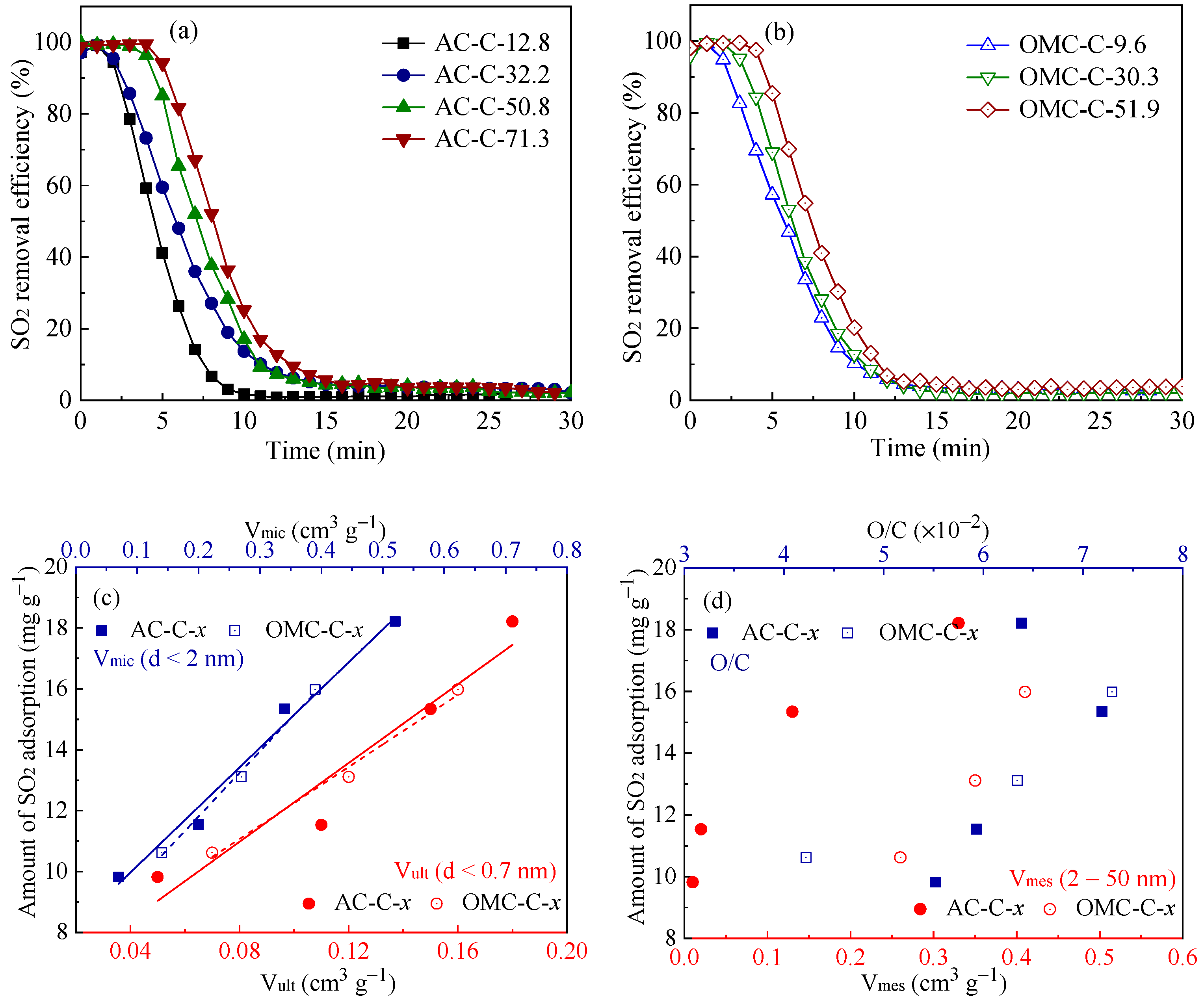
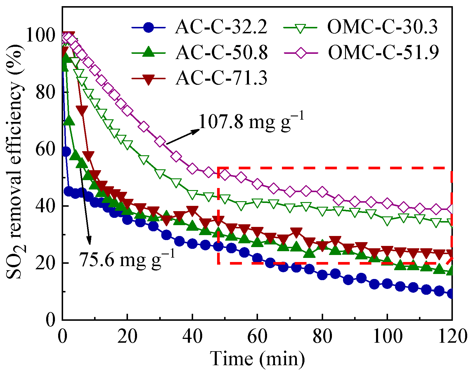
3.3. SO2 Removal Performance of Adsorbents

SO2 adsorption is the first step of subsequent oxidation and sulfuric acid-forming reactions within porous carbon. The SO2 separate adsorption dynamics were investigated for the AC and OMC samples, as shown in Figure 4a,b. The figures show that the SO2 removal efficiency reaches 100% at the initial stage and then rapidly declines with the adsorption time. Furthermore, for the two species of carbonaceous adsorbents, the removal efficiency and breakthrough time show an increasing trend with increasing burn-off as the pore volumes increase (Table 1).
To better understand the role of the pore structure, we investigated the effect of pore sizes and pore patterns within the adsorbents. From structure characterization, it appears that ultramicropore volume (Vult) and micropore volume (Vmic) directly contribute to the SO2 adsorption capacities of different samples, as shown in Figure 4c. Previous studies [33,37] have shown that micropores with diameters of approximately 0.7 nm may be important in SO2 adsorption because they largely enhance intermolecular interactions. In our experiments, the amount of SO2 adsorption increases linearly with Vult and Vmic and the fitting lines for AC-C-x and OMC-C-x almost coincide, which indicates that the pore sizes play a key role in SO2 adsorption rather than pore patterns. Meanwhile, it appears that neither the mesopore volume (Vmes) nor the O/C directly contribute to the amount of SO2 adsorption, as shown in Figure 4d.
Considering the presence of O2 and H2O in flue gas leading to a series of catalytic oxidation and H2SO4-forming reactions within carbonaceous adsorbents, the SO2 removal dynamics under simulated flue gas were investigated, as shown in Figure 5. Unlike the SO2 removal efficiency rapidly declining to 0 within 15 min in the SO2 separate adsorption process, the SO2 removal efficiency gradually declines to a value and almost maintains a plateau, as marked in the red box. Especially for OMC-C-30.3 and OMC-C-51.9, the SO2 removal efficiencies decline slower than that of AC-C-x, and the values of plateau remain higher than those of AC samples. Comparatively, OMC-C-51.9 greatly improves the sulfur capacity, reaching 107.8 mg g−1, as marked in Figure 5. AC-C-50.8, which has similar micropore characteristics, possesses a sulfur capacity of 75.6 mg g−1. Thus, different SO2 removal dynamics and sulfur capacities suggest that mesopore and pore patterns should have a coupling influence on SO2 removal in the presence of O2 and H2O.
To further elucidate the effect of pore structure, the changes of pore volumes, including Vult, Vsup, and Vmes, after adsorption of SO2 separately and reaction under SO2+O2+H2O conditions were investigated, as shown in Figure 6. These changes can be considered to be caused by the adsorption and storage of the main adsorbates (ex. SO2, SO3, and H2SO4). After the SO2 adsorption, the Vult of AC-C-50.8 and OMC-C-51.9 both decrease obviously compared to that of the pristine samples, while the Vsup decrease slightly and the Vmes have no change. These results suggest that SO2 adsorption mainly occurs in the micropores, especially in the ultramicropores, occupying the space of narrow pores with sizes smaller than 0.7 nm. Note that the decreasing Vult is in good agreement with the trend of SO2 adsorption capacities with Vult, as shown in Figure 4c, and further indicates that the ultramicropore is an important factor for high SO2 adsorption.
In the presence of O2 and H2O in flue gas, adsorbed SO2 within porous carbon reacts with O2 and H2O, catalyzed by carbon, to form the byproduct H2SO4, which can occupy the pore structure, thus hindering continuous SO2 adsorption. After reaction under SO2 + O2 + H2O conditions, the Vult, Vsup, and Vmes all show a decreasing trend, suggesting that the adsorbate H2SO4 exists in these storage spaces. Compared to AC-C-50.8, the Vult and Vsup of OMC-C-51.9 decrease to a much lesser extent. Meanwhile, the Vmes of OMC-C-51.9 show an obvious decrease. These results indicate that H2SO4 produced in the OMC-C-51.9 is much easier to transport and store in the mesopores, which may give rise to the recovery of micropores (ultramicropore and supermicropore), guaranteeing the continuous proceeding of the SO2 adsorption and transformation of sulfur-containing species. This is verified by the better SO2 removal performance of OMC-C-30.3 and OMC-C-51.9 in the presence of O2 and H2O (Figure 5). Although AC-C-50.8 also has a hierarchical pore configuration, unconnected micro- and mesoporous may be the obstacle in H2SO4 migration. Therefore, the pore pattern with micropores embedded in the ordered mesopores play a key role in the migration of byproducts and continuous SO2 removal in flue gas.

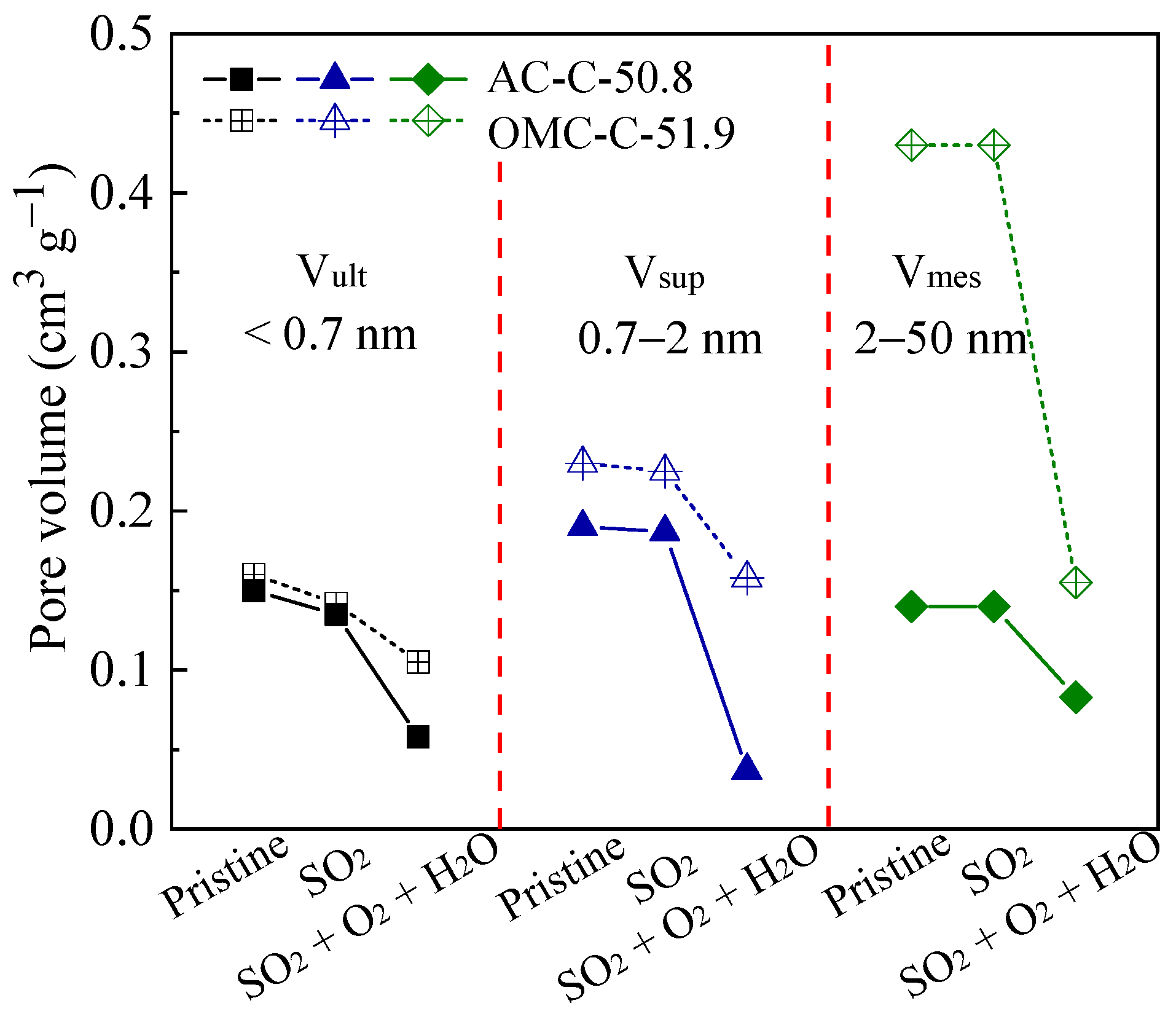
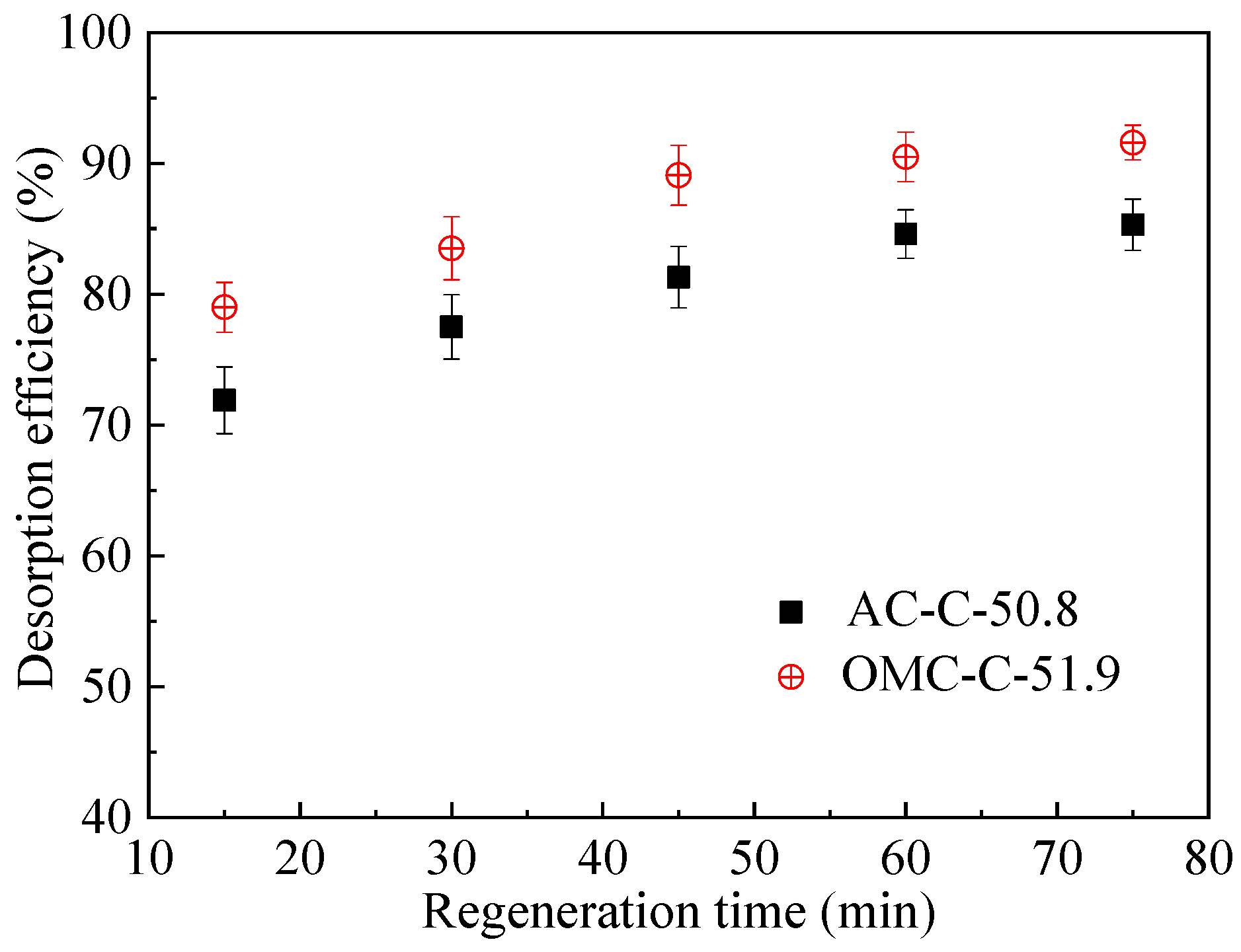
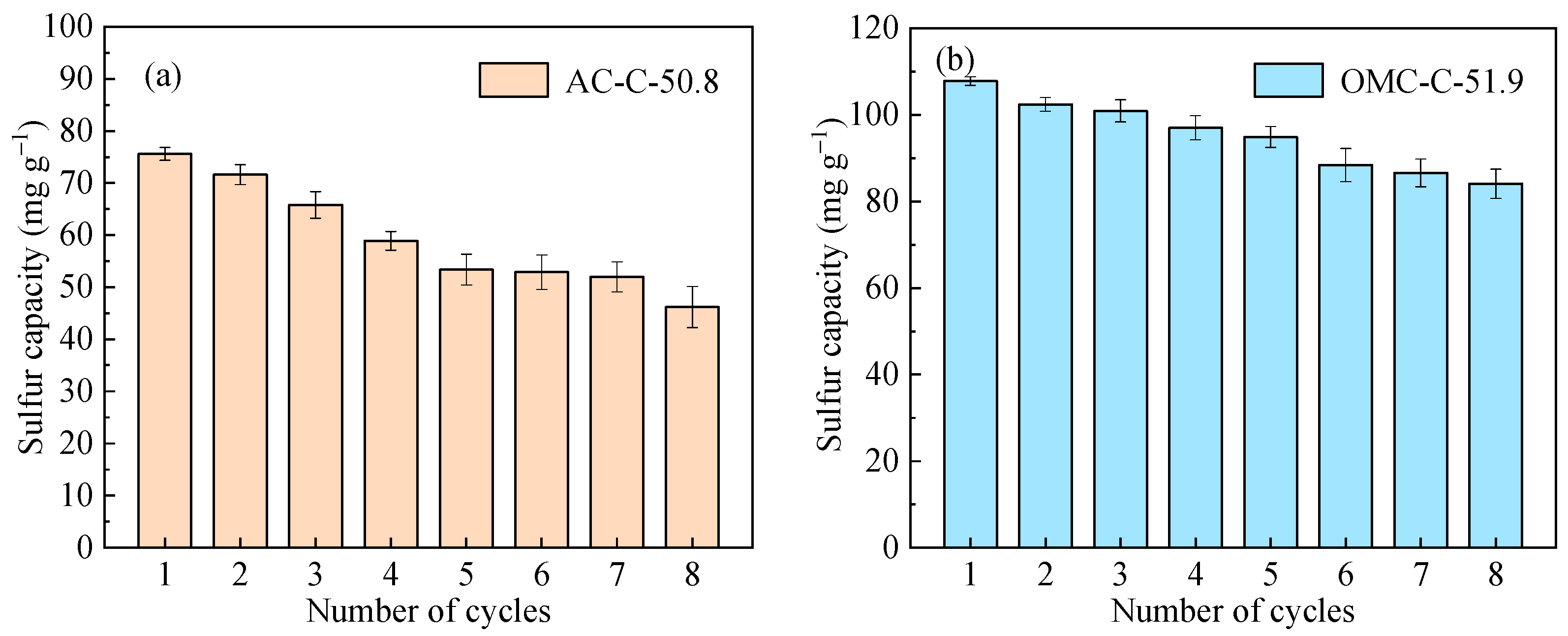
3.4. Regeneration and Cycling Stability Performance of Adsorbents

As reported in the literature [11,38,39,40], thermal regeneration is usually applied to extract the adsorbate H2SO4 based on the redox reaction (C + H2SO4 → CO2 + SO2 +H2O) between carbon and H2SO4 in the porous carbon. However, adsorbents will produce inevitable chemical loss, which usually leads to micropore damage and decay of SO2 removal performance. Thus, we chose the water-washing regeneration method and contrastively investigated the regeneration efficiency and eight cycles of desulfurization and regeneration performance of AC-C-50.8 and OMC-C-51.9. This regeneration method also provides new insight into the mass-transfer resistance in different interconnecting pore patterns.
Desorption of H2SO4 from saturated adsorbents was carried out with various regeneration times (15, 30, 45, 60, and 75 min) to determine the most appropriate desorption duration for adsorption–desorption cycling. As shown in Figure 7, the H2SO4 desorption efficiencies of AC-C-50.8 and OMC-C-51.9 increase from 71.9% to 85.3% and from 79.0% to 91.6% with increasing regeneration time. During 75 min regeneration, the H2SO4 desorption efficiencies are very close to the values of 60 min regeneration, suggesting that the desorption efficiency does not vary with time beyond 60 min. Thus, for recycling purposes, AC-C-50.8 and OMC-C-51.9 samples were regenerated by water scrubbing for 60 min. Moreover, desorption efficiencies indicate that adsorbate H2SO4 occurring in the OMC-C-51.9 is easier to extract from the inner pores, which is attributed to the reduction of the mass-transfer resistance in the hierarchical carbons with ordered mesopores.
To compare the effects of water-washing regeneration on desulfurized AC and OMC samples, the sulfur capacities versus cycling number of AC-C-50.8 and OMC-C-51.9 were investigated as shown in Figure 8. The working sulfur capacity of AC-C-50.8 shows a general decreasing trend from 75.6 mg·g−1 in the first-time desulfurization to 46.2 mg·g−1 in the 8th cycle with a reduction percentage of 40.5%, as shown in Figure 8a. The results indicate that incomplete desorption of H2SO4 from saturated adsorbents has an obviously negative impact on the cycling SO2 adsorption performance of AC-C-50.8. Similar results are observed with OMC-C-51.9. However, the sulfur capacity of OMC-C-51.9 decreases by 22.0% after eight cycles, which is much less than the rate of decrease of AC-C-50.8, suggesting that the characteristics of interconnecting micropores and ordered mesopores facilitate the desorption of H2SO4 and diminish the decrease of sulfur capacity.
To further examine the potential changes to the physical properties, the pore parameters of the eight times cycled water-washing regeneration AC-C-50.8 are listed in Table 1. Compared to pristine adsorbent, the BET surface area and micropore surface area of the adsorbent after eight cycles show an obvious decrease. Meanwhile, the ultramicropore and micropore volumes decrease from 0.15 to 0.05 cm3·g−1 and from 0.34 to 0.12 cm3·g−1, respectively. However, the mesopore volume shows little change after manifold cycles. That is, the decrease of sulfur capacity should be ascribed to the decrease of micropore volume as the sulfur-containing adsorbates remain in the inner pores. According to the regeneration performance of OMC-C-51.9, the ordered hierarchical pore configuration was found to facilitate the desorption of the adsorbates. Some species of surface functional groups may also lead to strong interactions between the adsorbed H2SO4 and the carbon surface, thus hindering the desorption of H2SO4, which will be further studied in our research.

4. Conclusions

In summary, two species of carbonaceous adsorbents were prepared, including coal-based activated carbons and hierarchical porous carbons with ordered mesopores. The physico-chemical characteristics and resulting SO2 adsorption and desorption performance were comparatively studied. The CO2 activation process of AC and OMC samples leads to abundant micropores, which are essential in enhancing the SO2-sorbent interactions. In particular, ultramicropore volume as the occurrence space of adsorbed SO2 directly contributes to the sulfur capacity for SO2 separate adsorption. With O2 and H2O participating in the gas composition, the SO2 removal efficiency appears to reach a plateau stage. Comparatively, the OMC sample, which has similar micropore characteristics to the AC sample, shows a much higher sulfur capacity, reaching 107.8 mg·g−1, mainly because of the ordered hierarchical porous configuration facilitating the transport of H2SO4 from micropores to mesopores. Meanwhile, the OMC sample promotes H2SO4 desorption efficiency with water-washing regeneration and cycled desulfurization–regeneration performance, further indicating that this pore pattern plays a key role in the diffusion and migration of adsorbates. The present results suggest that hierarchical pore configuration and interconnecting patterns, and not merely pore volumes, should be considered for optimizing heterogeneous gas–solid adsorption and reaction.

Author Contributions

Y.Z. and H.L. conceived and designed the experiments; Y.Z. and Y.M. carried out the experiments; Y.Z. wrote the paper; H.L. reviewed the paper.

Funding

This research was funded by the National Key Research and Development Program of China, grant number 2017YFB0602901, and the National Natural Science Foundation of China, grant number 51406131.

Conflicts of Interest

The authors declare no conflict of interest.

References

  1. Shi, L.; Yang, K.; Zhao, Q.P.; Wang, H.Y.; Cui, Q. Characterization and mechanisms of H2S and SO2 adsorption by activated carbon. Energy Fuels 2015, 29, 6678–6685. [Google Scholar] [CrossRef]
  2. Grzyb, B.; Albiniak, A.; Broniek, E.; Furdin, G.; Marêché, J.F.; Bégin, D. SO2 adsorptive properties of activated carbons prepared from polyacrylonitrile and its blends with coal-tar pitch. Microporous Mesoporous Mater. 2009, 118, 163–168. [Google Scholar] [CrossRef]
  3. Liu, C.F.; Shih, S.M. Effects of flue gas components on the reaction of Ca(OH)2 with SO2. Ind. Eng. Chem. Res. 2006, 45, 8765–8769. [Google Scholar] [CrossRef]
  4. Lisovskii, A.; Semiat, R.; Aharoni, C. Adsorption of sulfur dioxide by active carbon treated by nitric acid: I. Effect of the treatment on adsorption of SO2 and extractability of the acid formed. Carbon 1997, 35, 1639–1643. [Google Scholar] [CrossRef]
  5. Qu, Y.F.; Guo, J.X.; Chu, Y.H.; Sun, M.C.; Yin, H.Q. The influence of Mn species on the SO2 removal of Mn-based activated carbon catalysts. Appl. Surf. Sci. 2013, 282, 425–431. [Google Scholar] [CrossRef]
  6. Li, J.; Kobayashi, N.; Hu, Y. The activated coke preparation for SO2 adsorption by using flue gas from coal power plant. Chem. Eng. Process. 2008, 47, 118–127. [Google Scholar] [CrossRef]
  7. Sun, F.; Gao, J.H.; Liu, X.; Tang, X.F.; Wu, S.H. A systematic investigation of SO2 removal dynamics by coal-based activated cokes: The synergic enhancement effect of hierarchical pore configuration and gas components. Appl. Surf. Sci. 2015, 357, 1895–1901. [Google Scholar] [CrossRef]
  8. Yang, L.; Jiang, X.; Jiang, W.J.; Wang, P.; Jin, Y. Cyclic regeneration of pyrolusite modified activated coke by blending method for flue gas desulfurization. Energy Fuels 2017, 31, 4556–4564. [Google Scholar] [CrossRef]
  9. Liu, Q.Y.; Li, C.H.; Li, Y.X. SO2 removal from flue gas by activated semicokes-1. The preparation of catalysts and determination of operating conditions. Carbon 2003, 41, 2217–2223. [Google Scholar] [CrossRef]
  10. Yan, Z.; Liu, L.L.; Zhang, Y.L.; Liang, J.; Wang, J.; Zhang, Z.; Wang, X. Activated semi-coke in SO2 removal from flue gas: Selection of activation methodology and desulfurization mechanism study. Energy Fuels 2013, 27, 3080–3089. [Google Scholar] [CrossRef]
  11. Mochida, I.; Korai, Y.; Shirahama, M. Removal of SOx and NOx over activated carbon fibers. Carbon 2000, 38, 227–239. [Google Scholar] [CrossRef]
  12. Jastrzab, K. Properties of activated cokes used for flue gas treatment in industrial waste incineration plants. Fuel Process. Technol. 2012, 101, 16–22. [Google Scholar] [CrossRef]
  13. Ren, S.; Hou, Y.; Tian, S.; Wu, W.; Liu, W. Deactivation and regeneration of an ionic liquid during desulfurization of simulated flue gas. Ind. Eng. Chem. Res. 2012, 51, 3425–3429. [Google Scholar] [CrossRef]
  14. Ren, S.; Hou, Y.; Wu, W.; Jin, M. Oxidation of SO2 absorbed by an ionic liquid during desulfurization of simulated flue gases. Ind. Eng. Chem. Res. 2011, 50, 998–1002. [Google Scholar] [CrossRef]
  15. Davini, P. Flue gas desulphurization by activated carbon fibers obtained from polyacrylonitrile by-product. Carbon 2003, 41, 277–284. [Google Scholar] [CrossRef]
  16. Raymundo-Pinero, E.; Cazorla-Amoros, D.; Linares-Solano, A. Temperature programmed desorption study on the mechanism of SO2 oxidation by activated carbon and activated carbon fibres. Carbon 2001, 39, 231–242. [Google Scholar] [CrossRef]
  17. Karatepe, N.; Orbak, İ.; Yavuz, R.; Özyuğuran, A. Sulfur dioxide adsorption by activated carbons having different textural and chemical properties. Fuel 2008, 87, 3207–3215. [Google Scholar] [CrossRef]
  18. Wang, Z.M.; Kaneko, K. Effect of pore width on micropore filling mechanism of SO2 in carbon micropores. J. Phys. Chem. B 1998, 102, 2863–2868. [Google Scholar] [CrossRef]
  19. Mangun, C.L.; DeBarr, J.A.; Economy, J. Adsorption of sulfur dioxide on ammonia-treated activated carbon fibers. Carbon 2001, 39, 1689–1696. [Google Scholar] [CrossRef]
  20. Bagreev, A.; Bashkova, S.; Bandosz, T.J. Adsorption of SO2 on activated carbons: The effect of nitrogen functionality and pore sizes. Langmuir 2002, 18, 1257–1264. [Google Scholar] [CrossRef]
  21. Bashkova, S.; Armstrong, T.R.; Schwartz, V. Selective catalytic oxidation of hydrogen sulfide on activated carbons impregnated with sodium hydroxide. Energy Fuels 2009, 23, 1674–1682. [Google Scholar] [CrossRef]
  22. Bollini, P.; Didas, S.A.; Jones, C.W. Amine-oxide hybrid materials for acid gas separations. J. Mater. Chem. 2011, 21, 15100–15120. [Google Scholar] [CrossRef]
  23. Ghosh, M.; Lohrasbi, M.; Chuang, S.S.C.; Jana, S.C. Mesoporous titanium dioxide nanofibers with a significantly enhanced photocatalytic activity. ChemCatChem 2016, 8, 2525–2535. [Google Scholar] [CrossRef]
  24. Wickramaratne, N.P.; Jaroniec, M. Importance of small micropores in CO2 capture by phenolic resin-based activated carbon. J. Mater. Chem. A 2012, 1, 112–116. [Google Scholar] [CrossRef]
  25. Ghosh, M.; Liu, J.W.; Chuang, S.S.C.; Jana, S.C. Fabrication of hierarchical V2O5 nanorods on TiO2 nanofibers and their enhanced photocatalytic activity under visible light. ChemCatChem 2018, 10, 3305–3318. [Google Scholar] [CrossRef]
  26. Ryoo, R.; Joo, S.H.; Kruk, M.; Jaroniec, M.M. Ordered mesoporous carbons. Adv. Mater. 2001, 13, 677–681. [Google Scholar] [CrossRef]
  27. Pei, T.; Sun, F.; Gao, J.H.; Wang, L.J.; Pi, X.X.; Qie, Z.P.; Zhao, G.B. Introducing catalytic gasification into chemical activation for the conversion of natural coal into hierarchically porous carbons with broadened pore size for enhanced supercapacitive utilization. RSC Adv. 2018, 8, 37880–37889. [Google Scholar] [CrossRef]
  28. Davini, P. SO2 adsorption by activated carbons with various burnoffs obtained from a bituminous coal. Carbon 2001, 39, 1387–1393. [Google Scholar] [CrossRef]
  29. Zhu, Y.W.; Gao, J.H.; Li, Y.; Sun, F.; Gao, J.M.; Wu, S.H.; Qin, Y.K. Preparation of activated carbons for SO2 adsorption by CO2 and steam activation. J. Taiwan Inst. Chem. E. 2012, 43, 112–119. [Google Scholar] [CrossRef]
  30. Xiao, Y.; Liu, Q.Y.; Liu, Z.Y.; Huang, Z.G.; Guo, Y.X.; Yang, J.L. Roles of lattice oxygen in V2O5 and activated coke in SO2 removal over coke-supported V2O5 catalysts. Appl. Catal. B Environ. 2008, 82, 114–119. [Google Scholar] [CrossRef]
  31. Pietrzak, R. XPS study and physico-chemical properties of nitrogen-enriched microporous activated carbon from high volatile bituminous coal. Fuel 2009, 88, 1871–1877. [Google Scholar] [CrossRef]
  32. Wang, X.Q.; Lee, J.S.; Zhu, Q.; Liu, J.; Wang, Y.; Dai, S. Ammonia-treated ordered mesoporous carbons as catalytic materials for oxygen reduction reaction. Chem. Mater. 2010, 22, 2178–2180. [Google Scholar] [CrossRef]
  33. Sun, F.; Gao, J.H.; Zhu, Y.W.; Chen, G.Q.; Wu, S.H.; Qin, Y.K. Adsorption of SO2 by typical carbonaceous material: A comparative study of carbon nanotubes and activated carbons. Adsorption 2013, 19, 959–966. [Google Scholar] [CrossRef]
  34. To, J.W.F.; He, J.J.; Mei, J.G.; Haghpanah, R.; Chen, Z.; Kurosawa, T.; Chen, S.; Bae, W.; Pan, L.J.; Jeffrey, B.-H.T.; et al. Hierarchical N-doped carbon as CO2 adsorbent with high CO2 selectivity from rationally designed polypyrrole precursor. J. Am. Chem. Soc. 2016, 138, 1001–1009. [Google Scholar] [CrossRef]
  35. Jia, Y.F.; Xiao, B.; Thomas, K.M. Adsorption of metal ions on nitrogen surface functional groups in activated carbons. Langmuir 2002, 18, 470–478. [Google Scholar] [CrossRef]
  36. Biniak, S.; Szymanski, G.; Siedlewski, J. The characterization of activated carbons with oxygen and nitrogen surface groups. Carbon 1997, 35, 1799–1810. [Google Scholar] [CrossRef]
  37. Raymundo-Piñero, E.; Cazorla-Amorós, D.; Lecea, S.M.D.; Linares-Solano, A. Factors controling the SO2 removal by porous carbons: Relevance of the SO2 oxidation step. Carbon 2000, 38, 335–344. [Google Scholar] [CrossRef]
  38. Lizzio, A.A.; DeBarr, J.A. Mechanism of SO2 removal by carbon. Energy Fuels 1997, 11, 284–291. [Google Scholar] [CrossRef]
  39. Pi, X.X.; Sun, F.; Gao, J.H.; Zhu, Y.W.; Wang, L.J.; Qu, Z.B.; Liu, H.; Zhao, G.B. Microwave irradiation induced high-efficiency regeneration for desulfurized activated coke: A comparative study with conventional thermal regeneration. Energy Fuels 2017, 31, 9693–9702. [Google Scholar] [CrossRef]
  40. Ania, C.O.; Parra, J.B.; Menéndez, J.A.; Pis, J.J. Effect of microwave and conventional regeneration on the microporous and mesoporous network and on the adsorptive capacity of activated carbons. Microporous Mesoporous Mater. 2005, 85, 7–15. [Google Scholar] [CrossRef] [Green Version]
Figure 1. (ac) N2 adsorption and desorption isotherms at 77 K for the activated carbon (AC) and ordered mesoporous carbon (OMC) samples; (d) Barrett–Joyner and Halenda (BJH) mesopore size distribution plots of the AC and OMC samples. STP: Standard temperature and pressure.
Processes 07 00173 g001
Figure 2. Morphological characterizations of hierarchical porous carbons. TEM micrographs of (a) AC-C-50.8 (inset: Fast Fourier diffractogram), (b) OMC, and (c) OMC-C-51.9; (d) Small-angle XRD patterns of OMC and OMC-C-51.9.
Processes 07 00173 g002
Figure 3. FTIR spectra of the hierarchical carbons.
Processes 07 00173 g003
Figure 4. SO2-adsorption performance of the AC and OMC samples. SO2 removal efficiency for (a) AC-C-x and (b) OMC-C-x. Adsorption conditions: 2.5 g of adsorbents, 1500 ppm SO2, N2 balance, flow rate 1.2 L·min−1, at 313 K. The correlations of calculated SO2 adsorption amount and the physico-chemical parameters: (c) Ultramicropore volume (Vult) and micropore volume (Vmic); (d) mesopore volume (Vmes) and O/C.
Processes 07 00173 g004
Figure 5. SO2 removal efficiency versus time for AC and OMC samples. Reaction conditions: 2.5 g of adsorbents, 1500 ppm SO2, 5% O2, 10% H2O, N2 balance, flow rate 1.2 L·min−1, at 353 K.
Processes 07 00173 g005
Figure 6. Pore volume parameters of fresh adsorbents (pristine), adsorbents after adsorption of SO2 separately (SO2) and adsorbents after reaction under SO2 + O2 + H2O conditions. Samples: AC-C-50.8 and OMC-C-51.9. Pore volume parameters: Vult, supermicropore volume (Vsup, 0.7–2 nm) and Vmes, and the Vsup obtained by (Vmic–Vult).
Processes 07 00173 g006
Figure 7. Desorption efficiency versus regeneration time for AC-C-50.8 and OMC-C-51.9 by water-washing regeneration method.
Processes 07 00173 g007
Figure 8. Sulfur capacity of the adsorbent over eight adsorption-regeneration cycles. (a) AC-C-50.8; (b) OMC-C-51.9. Adsorption conditions: 2.5 g of adsorbents, 1500 ppm SO2, 5% O2, 10% H2O, N2 balance, for 2 h, at 353 K. Regeneration time: 60 min.
Processes 07 00173 g008
Table 1. The pore microstructural characteristics and elemental analysis of the samples.
SampleSBET 1
(m2 g−1)
Vult 2
(cm3 g−1)
Vmic 3
(cm3 g−1)
Vmes 4
(cm3 g−1)
Dmes 5
(nm)
Elemental Analysis (wt.%)
COO/C × 10−2
AC-C-x
AC-C-12.8149(138)0.050.070.012.7586.64.785.52
AC-C-32.2449(373)0.110.200.023.0885.65.085.93
AC-C-50.8809(537)0.150.340.143.1283.56.017.19
AC-C-50.8 after 8 cycles 6364(188)0.050.120.133.29
AC-C-71.31379(404)0.180.520.333.3180.85.166.38
OMC-C-x
OMC475(205)0.213.1795.13.43.58
OMC-C-9.6576(287)0.070.140.263.2794.74.04.22
OMC-C-30.3824(439)0.120.270.353.4493.15.96.34
OMC-C-51.91056(508)0.160.390.433.5191.96.77.29
1 SBET: Brunauer–Emmett–Teller (BET) surface area. The numbers in parentheses are micropore surface areas, calculated by the t-plot method. 2 Vult, 3 Vmic: Ultramicropore (<0.7 nm) volume and micropore (<2 nm) volume, calculated by the Horvath–Kawazoe (HK) method. 4 Vmes, 5 Dmes: Mesopore (2–50 nm) volume and median mesopore diameter, calculated by applying the BJH method. 6 AC-C-50.8 after 8 cycles: AC-C-50.8 sample after eight cycles of desulfurization and water-washing regeneration.

