Article

Flow Characteristics and Stress Analysis of a Parallel Gate Valve

1
SUFA Technology Industry Co., Ltd, CNNC, Suzhou 215129, China
2
Institute of Process Equipment, College of Energy Engineering, Zhejiang University, Hangzhou 310027, China
*
Author to whom correspondence should be addressed.
Processes 2019, 7(11), 803; https://doi.org/10.3390/pr7110803
Submission received: 29 September 2019 / Revised: 23 October 2019 / Accepted: 24 October 2019 / Published: 3 November 2019
(This article belongs to the Special Issue Smart Flow Control Processes in Micro Scale)

Abstract

:
Gate valves have been widely used in the piping system and have attracted a lot of attention from researchers. In this paper, a wedge-type double disk parallel gate valve is chosen to be analyzed. The Reynolds number varying from 200 to 500,000, and the valve opening degree varying from 20% to 100%, and the groove depth varying from 2.3 mm to 9 mm are chosen to investigate their effects on the flow and loss coefficients of the gate valve. The results show that the loss coefficient decreases and the flow coefficient increases with the increase of the Reynolds number and the valve opening degree, while with the increase of the groove depth, the loss coefficient barely changes, but the flow coefficient increases if the Reynolds number is larger than 10,000. In addition, the effects of the gaps between the disk and the limit stop on the stress distribution of the bolt are also investigated, and the results show that if the gaps are negative, high stress will act on the bolt at the contact position between the bolt and the limit stop.

1. Introduction

As a kind of on–off valve, gate valves are widely used in various process industries. When compared with other valves, it needs smaller torque during the open and close processes of the valve, and it also results in smaller flow resistance. However, due to the complexity of the sealing device, more components in gate valves are needed, which might lead to high proneness of gate valve failure [1,2,3].
Researches about various valves have been focused in the past years. For instance, Qian et al. [4,5] applied Tesla valves in the hydrogen decompression process and investigated the pressure drop and Mach number in multi-stage Tesla valves. Yuan et al. [6] and Jin et al. [7] conducted numerical simulations to study the cavitation inside the poppet valve and the globe valve, and the cavitation characteristics and the structural parameters that affected the cavitation were found. Dasgupta et al. [8] and Zhang et al. [9] and Qian et al. [10] focused on the dynamic valve open and close processes of a proportional valve, a pressure relief valve, and a pilot-control globe valve respectively. Furthermore, Jin et al. [11] and Qian et al. [12,13] investigated the structural parameters of a pilot-control angle valve and a micro Tesla valve, Xu et al. [14] focused on the pulsatile flow of a mechanical heart valve, Chen et al. [15] investigated the thermal stress of a pressure-reducing valve, and Qian et al. [16] analyzed the possibility of the noise distribution in perforated plates connecting pressure-relief valve.
Specific to the gate valves, lots of works have also been done focusing on different issues. There are works regarding the flow resistance and the temperature distributions. Solek and Mika [17] investigated the relationship between the loss coefficient and the Reynolds number for gate valves with ice slurry flow, and their experiments showed that the loss coefficient remained constant in the turbulent regime, but decreased with the increase of the Reynolds number in the laminar regime. Alimonti [18] and Lin et al. [19] studied the flow characteristics and resistance characteristics of a gate valve with different openings and different inlet velocities, and it was found that the flow resistance could be gradually stabilized when the opening was larger than 2/8 [19]. Long and Shurong [20] numerically investigated the flow and temperature distributions in the stem gate valve while using axisymmetric models, and Hu et al. [21] performed experiments and numerical simulations to study the temperature and the convection heat transfer coefficient distributions in a gate valve. In the meantime, there are also works regarding structure optimization [22,23], the corrosion erosion distributions [24,25,26], and the stress analysis [27,28,29]. Kolesnikov and Tikhonov [22] focused on the conicity of the output channel of the wedge gate valve and Xu et al. [23] focused on the seal and piston of a subsea gate valve. Babaev and Kerimov [24] found that there was fretting corrosion for a parallel slide gate valve. Lin et al. [25,26] found that the erosion rate in a gate valve was related to the pipe diameter, the cavity width, and the inlet velocity [25], while the open degree had little effects but a large Stokes number could increase the difference of erosion distributions for different valve placements [26]. As for the stress analysis, Liao et al. [27] found that the fatigue of the inlet valve sleeve resulting from collision stress was the main reason for the valve failure. Zakirnichnaya and Kulsharipov [28] analyzed the stress-strain of the wedge gate valves while using fluid-structure interaction technology and they found that the safe operation resources value of the wedge is lower than the valve body. Punitharani et al. [29] applied the finite element analysis (FEA) method to evaluate the residual stresses in a gate valve, and they found that there were large tensile and compressive residual stresses on the circular bead of the gate valve.
Gate valves can be classified into the wedge gate valve, the parallel gate valve, the double disk parallel gate valve, and the double disk wedge gate valve, etc. according to the form of the sealing device. As described above, works regarding parallel gate valves [18,19] and wedge gate valves [22] have been done by researchers. In this paper, a wedge-type double disk parallel gate valve is chosen to be analyzed. The computational fluid dynamics method is used to investigate the flow and loss characteristics under different Reynolds number and different groove depth. Moreover, the structural stress analysis where the valve failure might occur is also done while using a numerical method that is proven by the previous studies [27,28,29,30,31]. This work is helpful for the understanding of the flow characteristics of the gate valve and the judgment of the reason for valve failure in the future.

2. Model Description
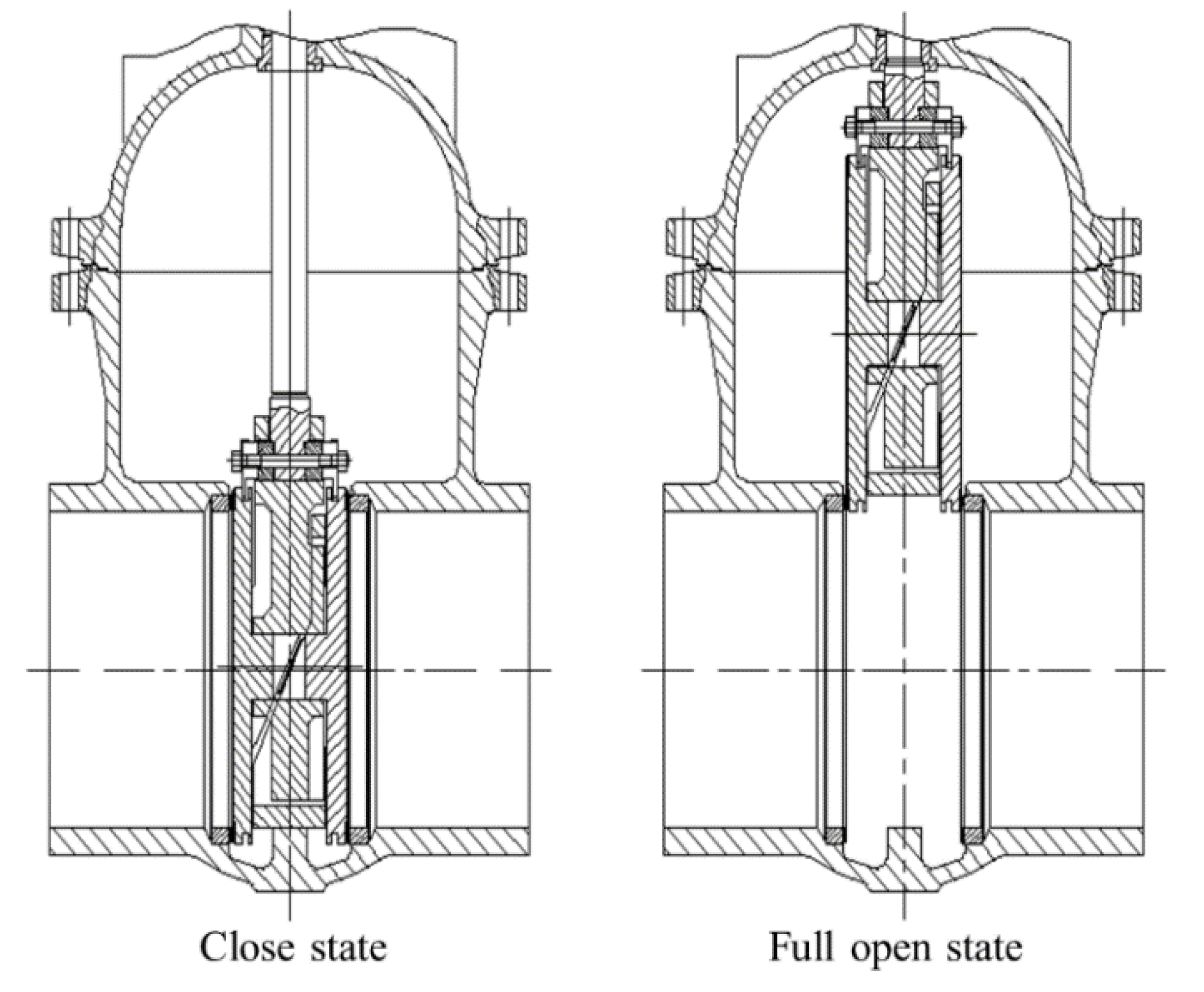
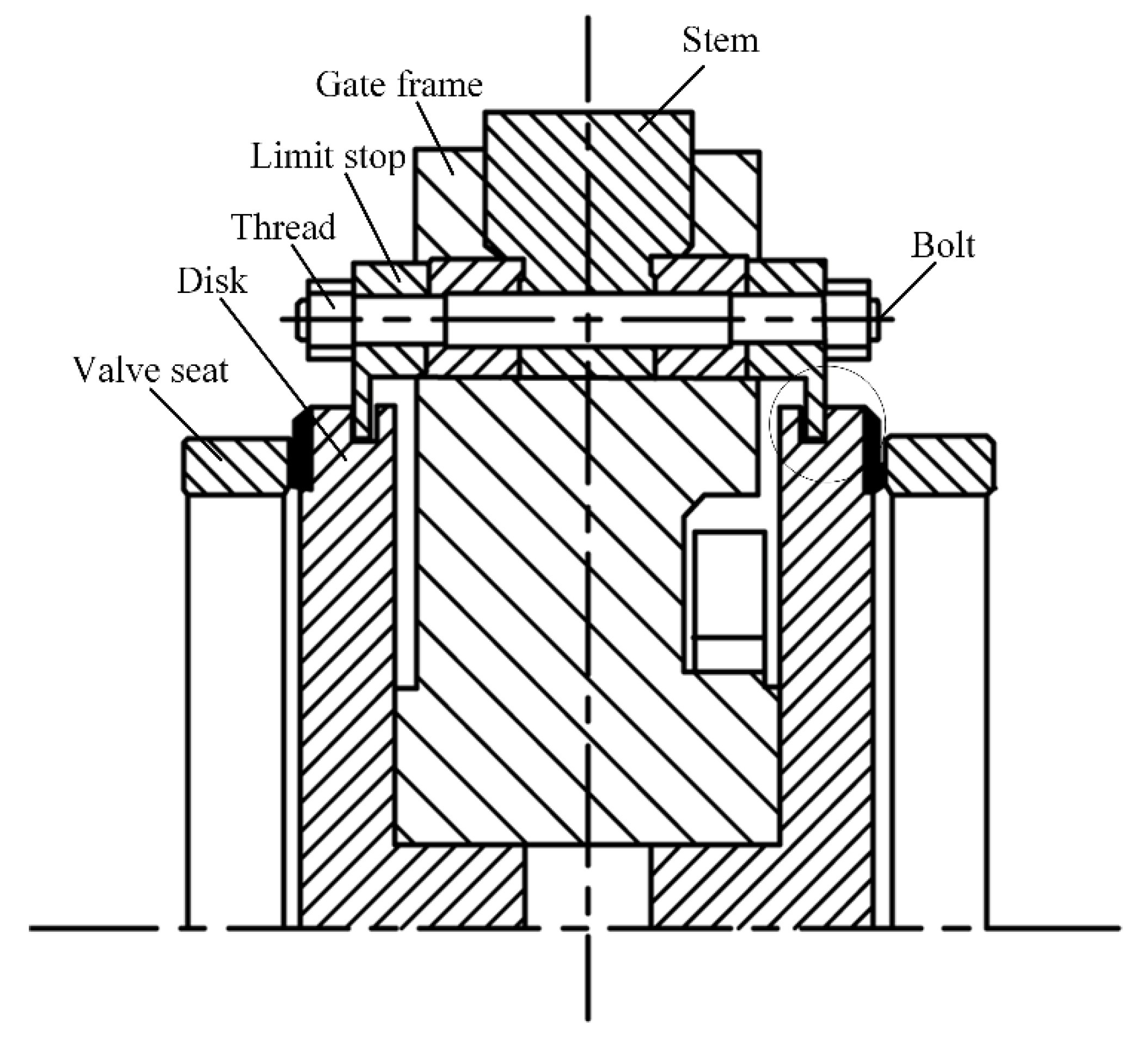
2.1. Physic Model

Figure 1 shows the structure of the investigated gate valve and the nominal diameter is 100 mm. Figure 2 shows the detailed illustration of the disk component, which mainly consists of the disk, the disc frame, the nut, the limit stop, and the bolt.
Figure 3 shows the gaps between the disk and the limit stop. During the mechanical machining process, there might be an asymmetry degree of the opening size of the machine. If the asymmetry degree is too large, gaps C2 and C3 can become negative, which will lead to extra force acting on the bolt.
Figure 4 shows the simplified model of the bolt and the limit stop; here, the nominal diameter of the thread is 6 mm, the diameter of the bolt is chosen as 7 mm, and the minimum diameter of the thread is chosen as 4.917 mm.

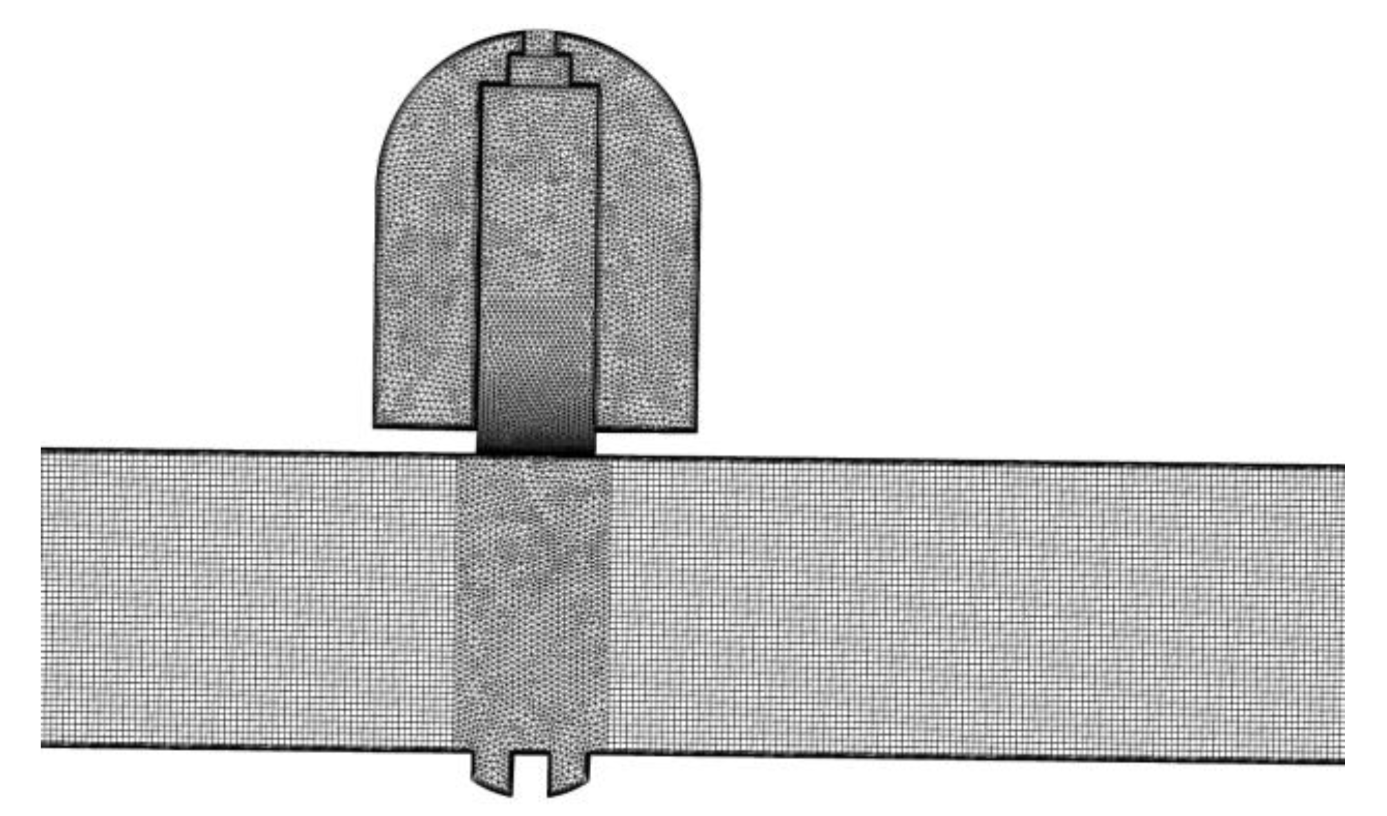
2.2. Numerical Model

The commercial software package ANSYS is used in this paper. The software Fluent that is based on the finite volume method is used to analyze the flow and resistance characteristics, and the software Mechanical based on the finite element method is used to predict the stress of the bolt. To solve the fluid field, the continuity and the momentum equations are used and are shown in the following.
x j ( u j ) = 0
x j ( ρ u i u j + p δ i j τ i j ) = 0
here ρ stands for the density of the fluid, u stands for the velocity of the fluid, p stands for the pressure of the fluid, and τij stands for the viscous stress. The Realizable k-ε turbulence model [32] is used to solve the turbulent flow inside the investigated wedge-type double disk parallel gate valve, and the transport equations for turbulence kinetic and turbulence dissipation are shown, as follows
x j ( ρ k u ) = x j [ ( μ + μ t σ k ) k x j ] + G k + G b ρ ε Y M + S K
x j ( ρ ε u ) = x j [ ( μ + μ t σ ε ) ε x j ] + ρ C 1 S ε ρ C 2 ε 2 k + v ε + C 1 ε ε k C 3 ε G b + S ε
here the model constants appear in above equations are σk = 1.0, σε = 1.2, C1ε = 1.44, and C2 = 1.9.
The hybrid grid is adopted during the computational fluid dynamics simulations and it is shown in Figure 5. A grid independence check is done for the wedge-type double disk parallel gate valve with a different total number of cells, N, and the pressure drop, ∆p, between the upstream and the downstream of the gate valve is shown in Table 1. From Table 1, it can be found that, when the cell numbers increase from 13.3 × 10⁵ to 25.3 × 10⁵, the variation of the pressure drop is within 0.9%, so the method that is used to generate the grid 2 is adopted in this study.
Water under room temperature is chosen as the working fluid inside the investigated gate valve. During the fluid flowing process, the temperature of water in the upstream of the gate valve and the ambient temperature are the same, which makes a small variation of water temperature. Therefore, the Energy equation is not solved. Symmetrical models are used to save simulation time. The velocity inlet and the pressure outlet boundary conditions are applied, and the outlet pressure is set as the atmosphere in order to investigate the flow and loss coefficients of the wedge-type double disk parallel gate valve. In addition, the no-slip wall is adopted for the wall boundary. For the stress analysis of the bolt, the symmetry plane is set as frictionless support, and the face of the bolt is set as fixed support.

2.3. Model Validation

The numerical results are compared with the experimental results of Lin et al. [19] in order to validate the used methods in this study. Here, the mentioned numerical methods are used to solve the turbulent incompressible gas flow in a parallel gate valve. Table 2 shows the comparison of the loss coefficients, and ξE represents the experimental results and ξN represents the numerical results. From Table 2, it can be found the relative errors between the experimental results and the numerical results are within 3%, thus the applied methods in this study are appropriate and they can provide results with sufficiently precise.

3. Results and Discussion

The flow and loss characteristics of the wedge-type double disk parallel gate valve are numerically investigated, and the effects of the valve opening degree and the groove depth are studied. In addition, the stress analysis is done to uncover the possible reason for the gate valve failure.

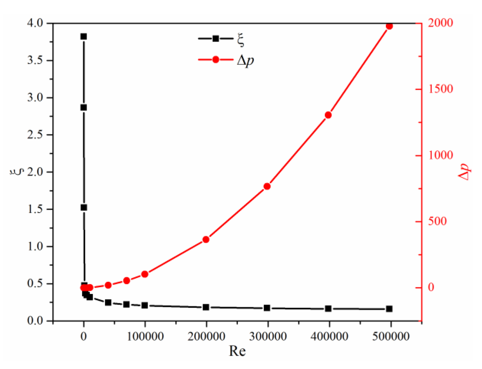
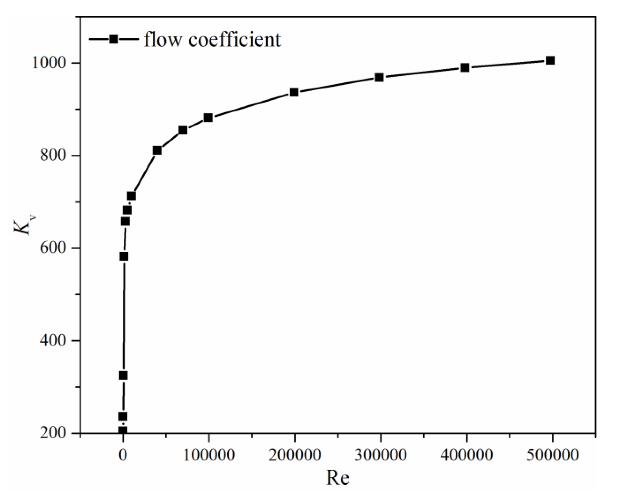
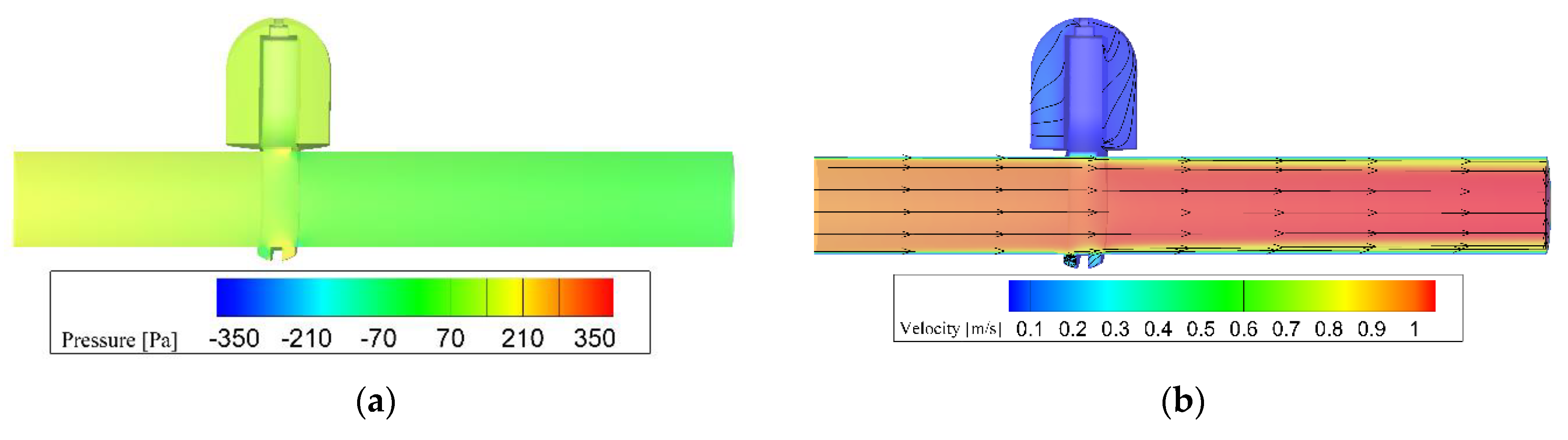
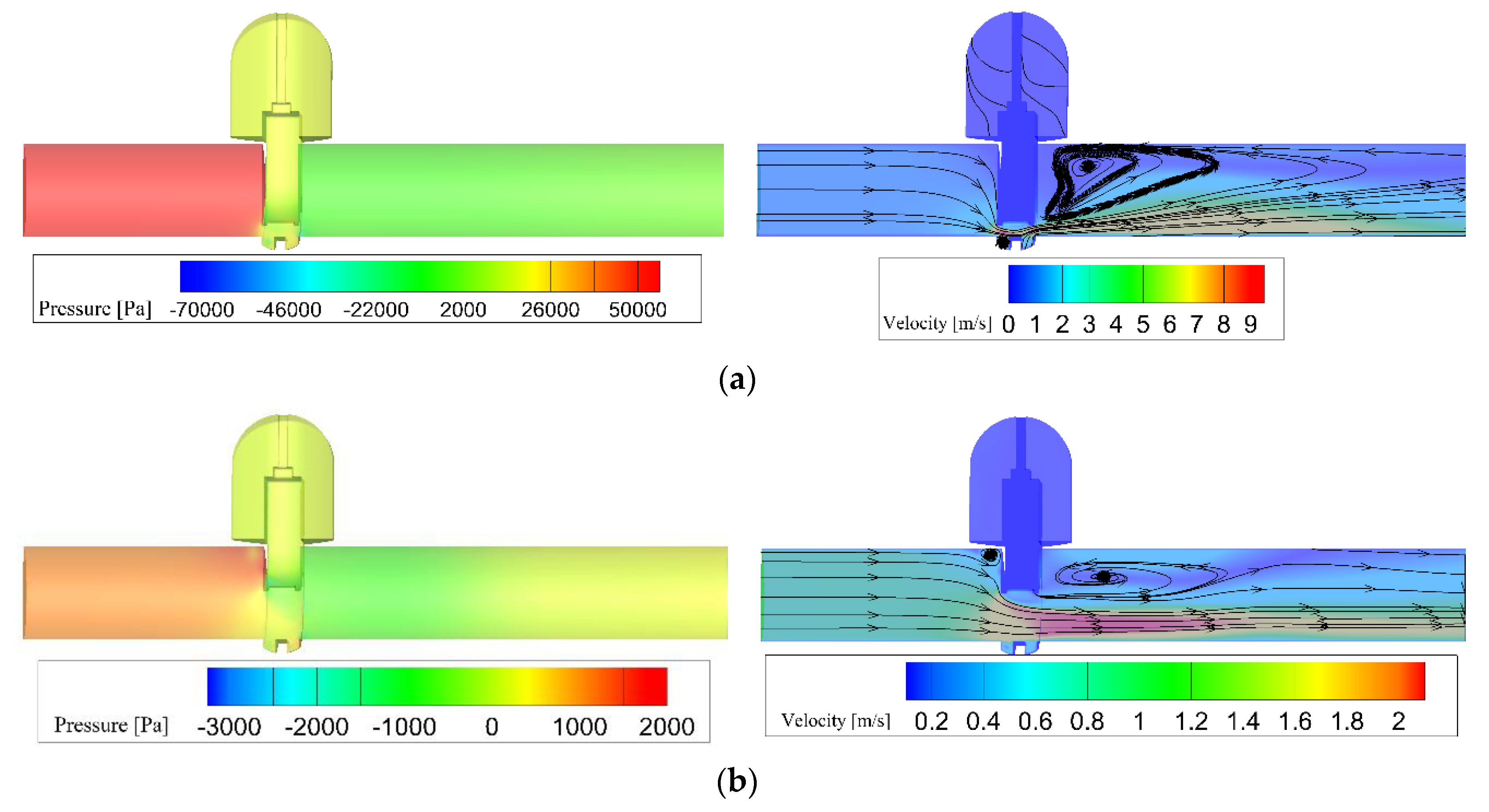
3.1. Flow and Loss Characteristics

When water flows through the wedge-type double disk parallel gate valve, there is a pressure drop. The loss coefficient is often used as an indicator of the valve flow capacity, and the greater the loss coefficient, the smaller the valve flow capacity, but the greater the pressure drop. The loss coefficient of a valve can be calculated from the below equation.
ξ = Δ p 1 / 2 ρ v 2
Figure 6 shows the pressure drop ∆p and the loss coefficient ξ of the investigated gate valve with the Reynolds number varying from 200 to 500,000. It can be found that the pressure drop almost exponentially increases with the increase of the Reynolds number. For the loss coefficient, as the increase of the Reynolds number, it decreases rapidly first and then has very small variation, and there is the largest variation of the loss coefficient when the flow is laminar.
The capacity of water flows through the investigated gate valve can be represented by the flow coefficient, which can be expressed in the following
K v = 10 Q 1000 ρ Δ p ρ 0
here Q is the volume flux (m3/h), ρ0 is the density of water at 15 °C, Kv is the flow coefficient and it represents the flux when the pressure drop of the gate valve is 100 kPa. Figure 7 shows the relationship between the flow coefficient and the Reynolds number. It can be found that the flow coefficient increases with the increase of Reynolds number, and the smaller the Reynolds number, the larger the variation of the flow coefficient.
To investigate the internal flow and pressure fields, the pressure and velocity distributions on the symmetry plane when the Reynolds number is about 100,000 are shown in Figure 8. It can be found that, when the investigated gate valve is in the fully open position, the whole main pipe in the gate valve is full of water with high speed, and the main resistance of the gate valve is the channel for the movement of the disk. Thus, the pressure drop is relatively small if the gate valve is in the fully open position and the loss coefficient is close to zero.

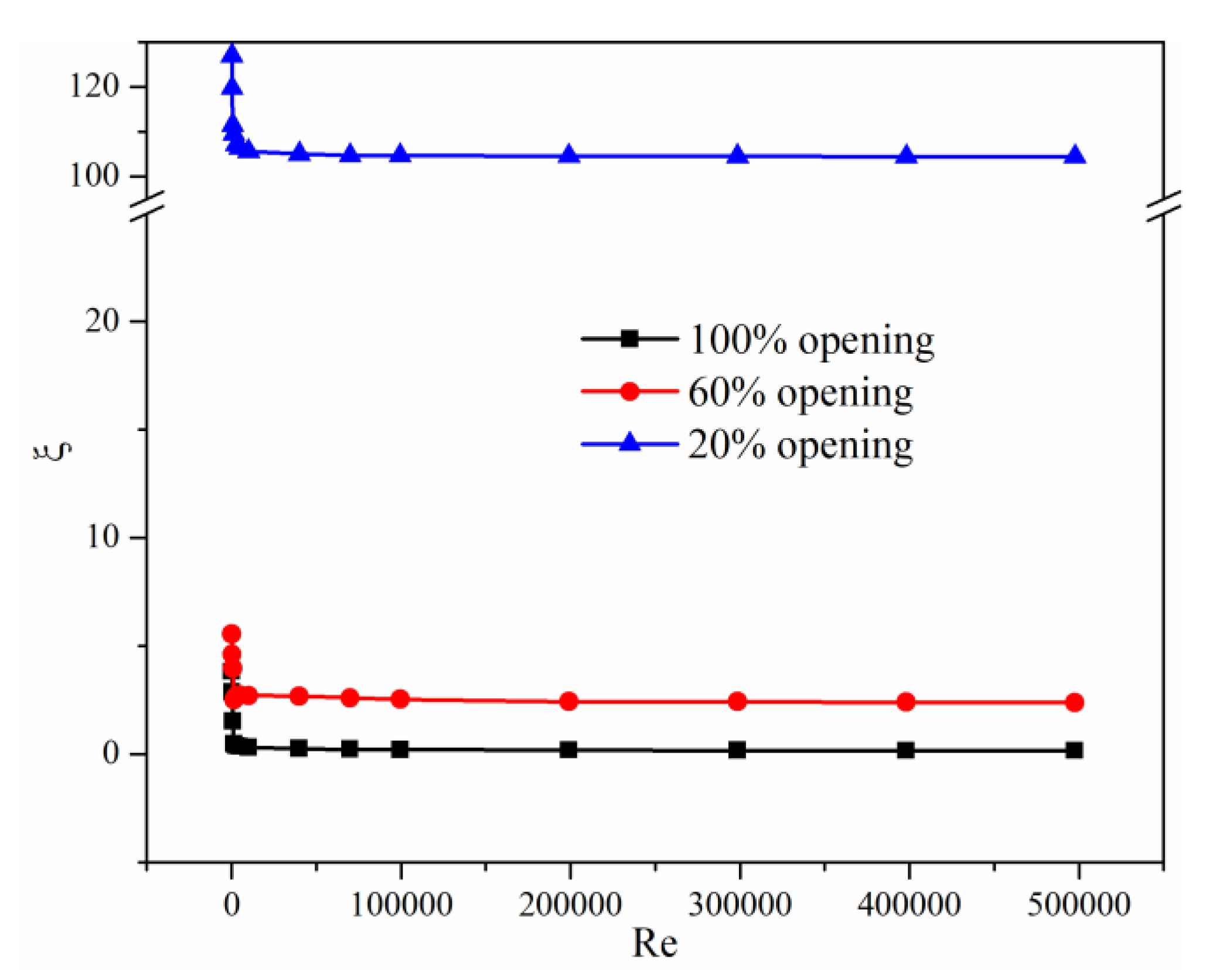
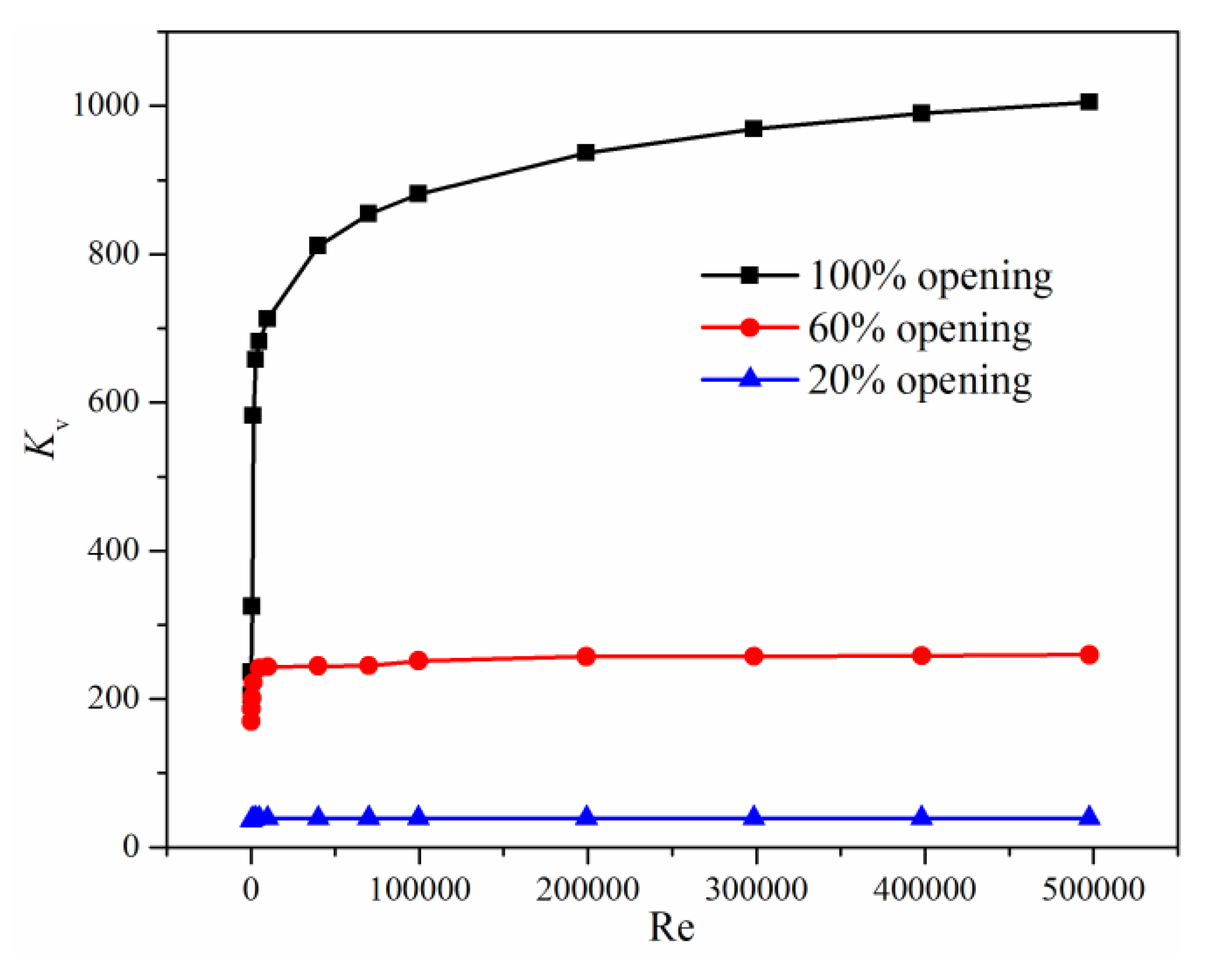
3.2. Effects of Valve Opening Degree

Figure 9 shows the internal flow fields and pressure distributions under two different valve opening degrees. Pressure drop mainly appears at the downstream of the gate valve that results from the throttling effect of two disks. With the decrease of the valve opening degree, the flow area decreases and the throttling effect increases, so the upstream pressure increases as the downstream pressure remains constant. Together with Figure 8, it can be found that, when the gate valve is in a 100% opening degree, the water flows directly to the downstream pipe, and there is no swirl in the main pipe of the valve. As the valve opening degree decreases, the maximum velocity increases and it appears under the valve disks. When comparing the gate valve with a 60% opening degree and the gate valve with a 20% opening degree, the maximum velocity increases from 2.2 m/s to 9.3 m/s. From the water streamline under different valve opening degree, it can be found that there is a local recirculation region with low velocity behind the valve disk, and the smaller the valve opening degree, the greater the local recirculation region.
The loss coefficient and flow coefficient under different valve opening degree are shown in Figure 10 and Figure 11. It can be found that the valve opening degree does not affect the relationship between the loss coefficient, the flow coefficient, and the Reynolds number. If the Reynolds number is smaller than 5000, the loss coefficient decreases with the increase of the Reynolds number rapidly, and the flow coefficient increases sharply as the increase of the Reynolds number. While the Reynolds number is larger than 5000, the loss coefficient barely varies with the increase of the Reynolds number, but the flow coefficient still increases with a reduced increment as the increase of the Reynolds number.

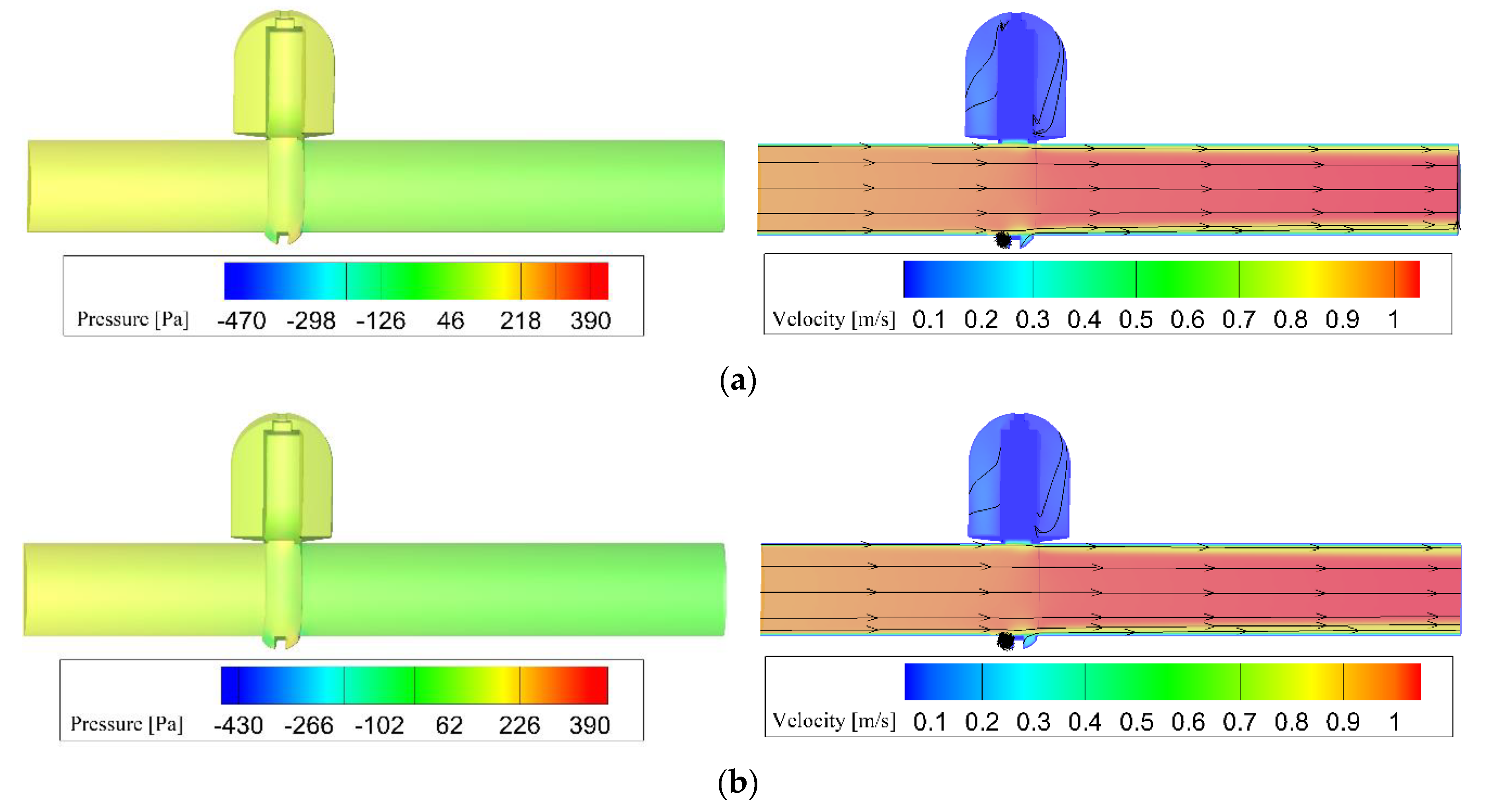
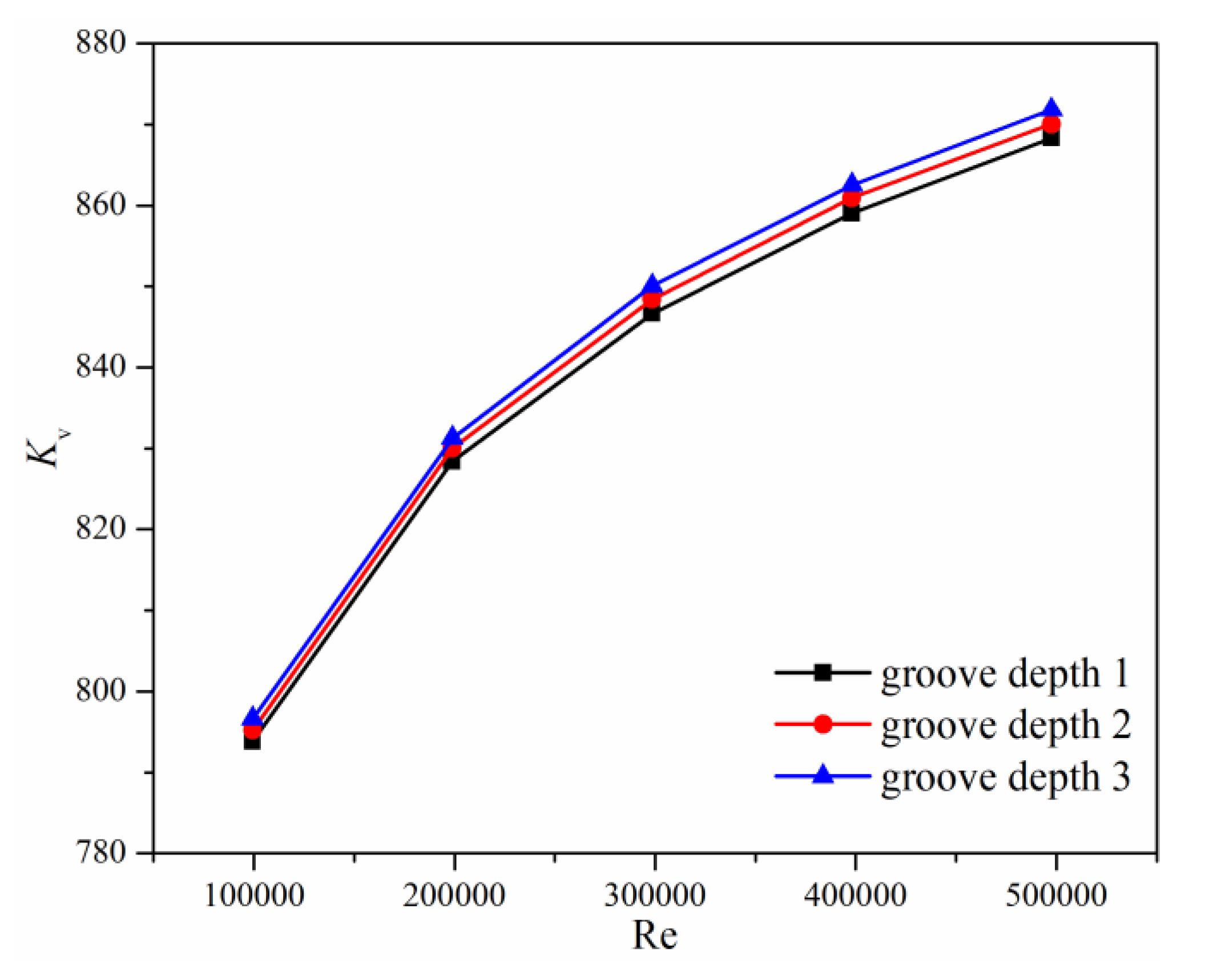
3.3. Effects of the Groove Depth

When the wedge-type double disk parallel gate valve is fully closed, the contact area between the gate valve disks and the valve seat is an annulus, and the size of the annulus can be judged by the groove depth. Three different groove depths are chosen, namely groove depth 1 (2.3 mm), groove depth 2 (4.5 mm), and groove depth 3 (9 mm) to investigate the effects of the groove depth on the flow and loss characteristics of the investigated gate valve.
The pressure and velocity distributions of the investigated gate valve with groove depth 3 are shown in Figure 8, and the pressure and velocity distributions of the investigated gate valve with groove depth 1 and groove depth 2 are shown in Figure 12. Together with Figure 8 and Figure 12, it can be found that the groove depth does not affect the water streamline, which is because the flow channel is similar under different groove depth. While for the water pressure in the investigated gate valve, although the pressure distributions are almost the same, the value of water pressure increases as the groove depth decreases, which results from the resistance loss in the vicinity of the valve seat.
The loss coefficient and flow coefficient of the investigated gate valve with different groove depth are shown in Table 3 and Figure 13. It can be seen from Table 3 that the groove depth does not affect the loss coefficient. Although pressure drop increases with the decrease of the groove depth, the difference can be neglected in the expression of the loss coefficient. When the Reynolds number is smaller than 10,000, the flow coefficient is not affected by the groove depth, while the Reynolds number is larger than 10,000, the flow coefficient increases with the increase of the groove depth, and the larger the Reynolds number, the larger the difference of the flow coefficient. Therefore, a large groove depth should be designed if possible.

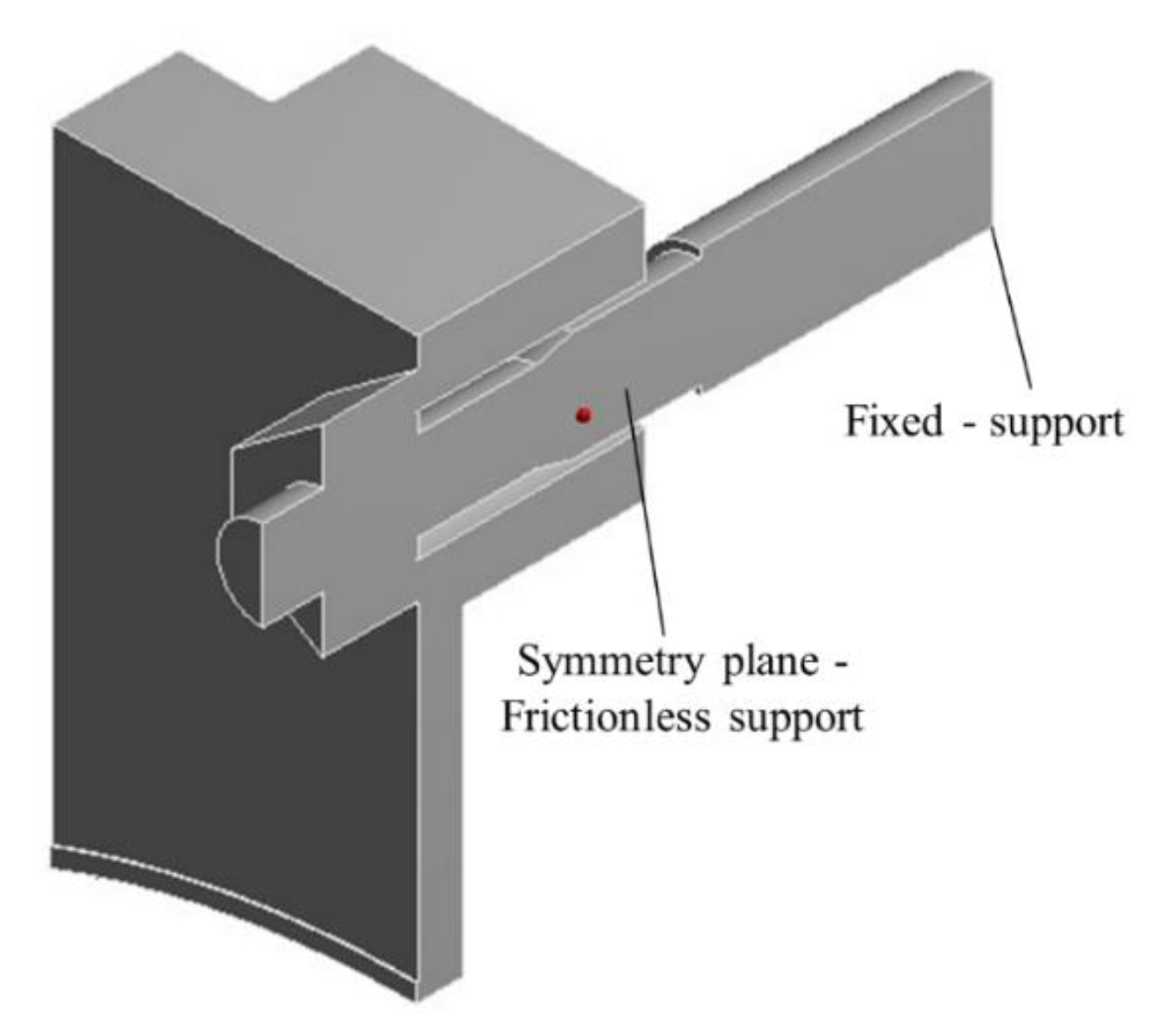
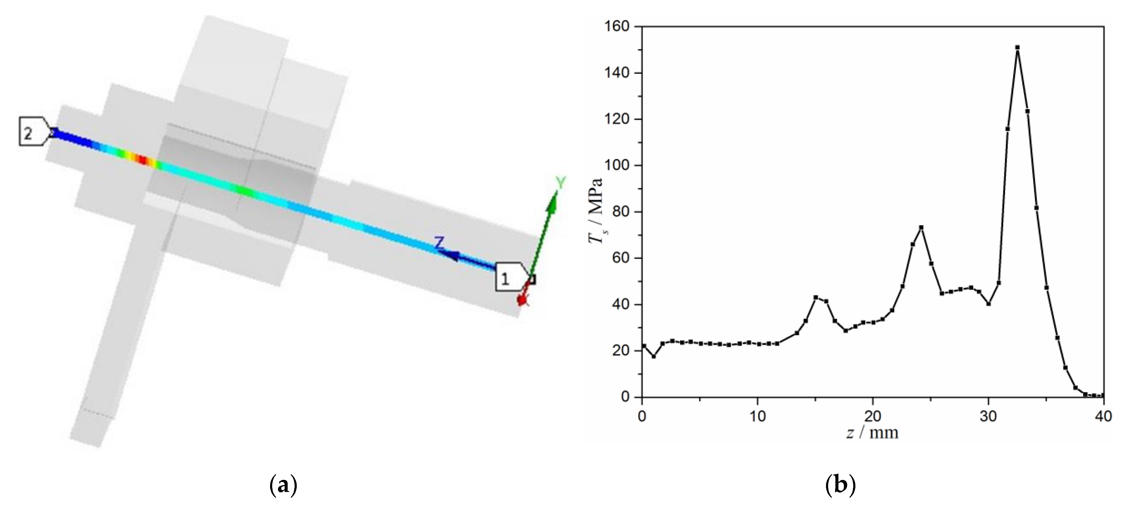
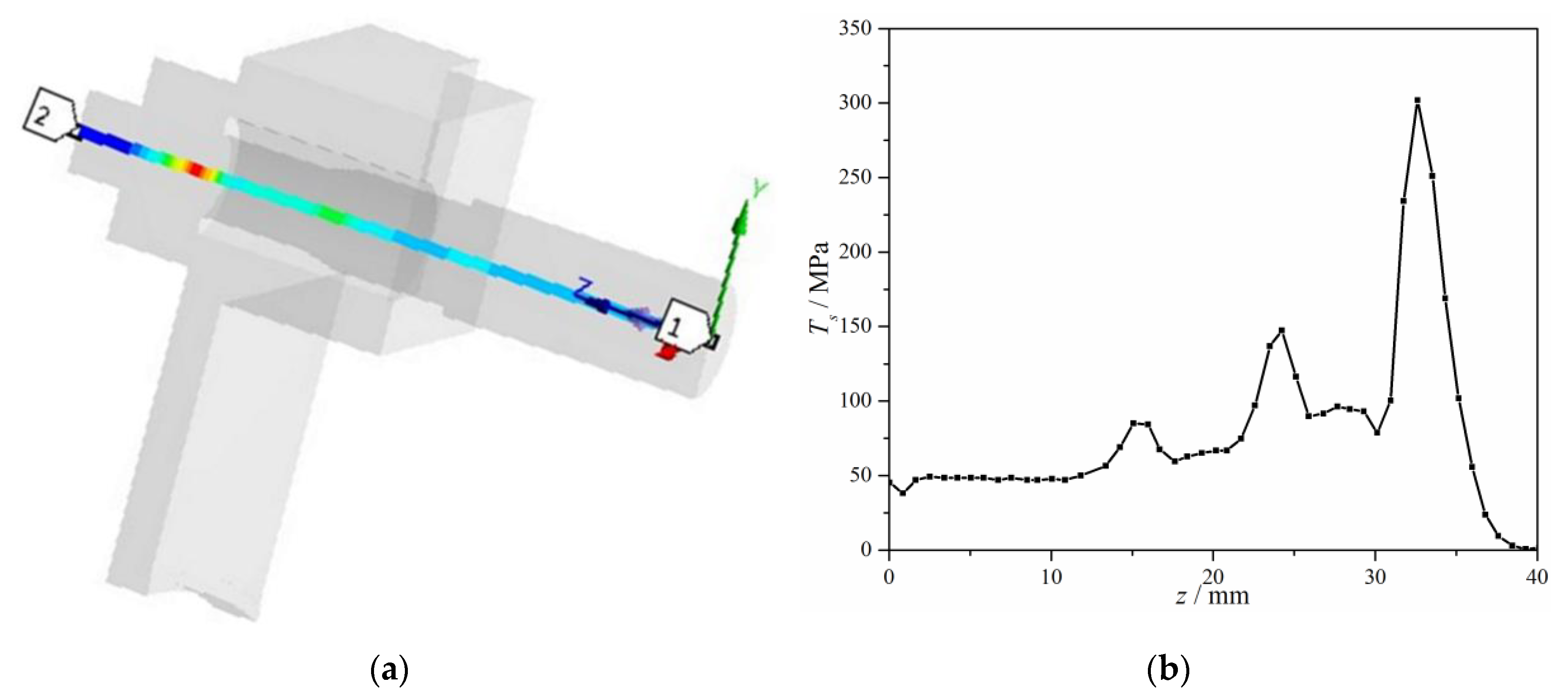
3.4. Stress Analysis of the Bolt

The wedge-type double disk parallel gate valve has a complex actuator component, where there is a high possibility of the occurrence of valve failure. The following part focuses on the stress distribution on the bolt in order to find out one of the reasons for valve failure.

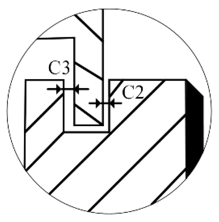
3.4.1. Effects of the Gap C2

If the limit stop shifts to the gate during the mechanical machining process, the gap C2 will become negative. To investigate the effect of gap C2 on the state of the stress distribution of the bolt, the value of gap C2 is assumed to be −0.5 mm.
The stress linearization analysis of the transverse cross-section of the bolt is shown in Figure 14a, and the distribution of the total stress, Ts, which equals to the membrane stress plus the bending stress, is shown in Figure 14b.
It can be found in Figure 14 that the maximum of the stress is 152.1 MPa, and the location where there is the maximum stress is 32.5 mm away from the end face of the bolt, where the contact position of the bolt and the limit stop is.

3.4.2. Effects of the Gap C3

If the limit stop shifts away from the gate during the mechanical machining process, the gap C3 will become negative. The value of gap C3 is assumed to be −1 mm to investigate the effect of gap C3 on the state of the stress distribution of the bolt.
Figure 15a shows the stress linearization analysis of the transverse cross-section of the bolt and Figure 15b shows the distribution of the total stress.
It can be seen from Figure 15 that the maximum of the stress is 303.1 MPa and the location where there is the maximum stress is 32.5 mm away from the end face of the bolt. Combining Figure 14 and Figure 15, it is found that the stress distribution along the axial direction of the bolt is almost the same when the gap C2 or C3 is negative. Hence, the machining accuracy has great influence on the service life of the valve.

4. Conclusions

Numerical methods are adopted to investigate the flow and loss characteristics and the stress distribution of the wedge-type double disk parallel gate valve. The effects of the Reynolds number, the valve opening degree, and the groove depth are focused. In the meantime, the effects of the gaps between the disk and the limit stop are also discussed. The results show that the loss coefficient decreases, but the flow coefficient increases with the increase of Reynolds number. When Reynolds number is smaller than 5000, the variation of the flow and loss coefficients is very large. While Reynolds number is larger than 5000, the variation of the flow coefficient decreases and the loss coefficient almost remains the same. The valve opening degree has great influence on the flow and loss characteristics, with the decrease of the valve opening degree, the loss coefficient increases rapidly, and the flow coefficient obviously decreases. As for the groove depth, it has negligible effects on the loss coefficient, but the larger the groove depth, the larger the flow coefficient if the Reynolds number is greater than 10,000. The existence of the gaps between the disk and the limit stop is to eliminate the stress acting on the bolt, if the gaps are negative, high stress will appear at the contact position between the bolt and the limit stop. During the design process, a large groove depth should be chosen to provide a large flow coefficient. While, during the machining process, the machining accuracy should be satisfied to avoid stress concentration of the bolt.

Author Contributions

Conceptualization, H.W. and J.-y.L.; Data curation, J.-y.L. and Z.-x.G.; Formal analysis, H.W. and J.-y.L.; Investigation, J.-y.L.; Methodology, H.W.; Project administration, H.W. and J.-y.L.; Resources, H.W. and J.-y.L.; Software, J.-y.L. and Z.-x.G.; Supervision, H.W.; Validation, J.-y.L.; Writing—review & editing, J.-y.L.

Funding

This research received no external funding.

Conflicts of Interest

The authors declare no conflict of interest. The funders had no role in the design of the study; in the collection, analyses, or interpretation of data; in the writing of the manuscript, or in the decision to publish the results.

References

  1. Barsoum, I.; Muñoz, A. Failure Analysis of a Large Knife Gate Valve Subjected to Multiaxial Loading. In Proceedings of the ASME 2017 Pressure Vessels and Piping Conference, Waikoloa, HI, USA, 16–20 July 2017; American Society of Mechanical Engineers Digital Collection: New York, NY, USA, 2017. [Google Scholar]
  2. Owen, D.M.; Beavers, J.A. Investigation of Bolt Failures on a Gate Valve from a Natural Gas Pipeline. In Proceedings of the 4th International Pipeline Conference, Calgary, AB, Canada, 29 September–3 October 2002; American Society of Mechanical Engineers Digital Collection: New York, NY, USA, 2002. [Google Scholar]
  3. Ifezue, D.; Tobins, F. Failure Investigation of a Gate Valve Eye Bolt Fracture During Hydrotesting. J. Fail. Anal. Prev. 2013, 13, 249–256. [Google Scholar] [CrossRef]
  4. Qian, J.Y.; Chen, M.R.; Gao, Z.X.; Jin, Z.J. Mach number and energy loss analysis inside multi-stage Tesla valves for hydrogen decompression. Energy 2019, 179, 647–654. [Google Scholar] [CrossRef]
  5. Qian, J.Y.; Wu, J.Y.; Gao, Z.X.; Wu, A.; Jin, Z.J. Hydrogen decompression analysis by multi-stage Tesla valves for hydrogen fuel cell. Int. J. Hydrogen Energy 2019, 44, 13666–13674. [Google Scholar] [CrossRef]
  6. Yuan, C.; Song, J.; Zhu, L.; Liu, M. Numerical investigation on cavitating jet inside a poppet valve with special emphasis on cavitation-vortex interaction. Int. J. Heat Mass Transfer 2019, 141, 1009–1024. [Google Scholar] [CrossRef]
  7. Jin, Z.J.; Gao, Z.X.; Qian, J.Y.; Wu, Z.; Sunden, B. A parametric study of hydrodynamic cavitation inside globe valves. ASME J. Fluids Eng. 2018, 140, 031208. [Google Scholar] [CrossRef]
  8. Dasgupta, K.; Ghoshal, S.K.; Kumar, S.; Das, J. Dynamic analysis of an open-loop proportional valve controlled hydrostatic drive. Proc. Inst. Mech. Eng. Part E 2019, 0954408919861247. [Google Scholar] [CrossRef]
  9. Zhang, Z.; Jia, L.; Yang, L. Numerical simulation study on the opening process of the atmospheric relief valve. Nucl. Eng. Des. 2019, 351, 106–115. [Google Scholar] [CrossRef]
  10. Qian, J.Y.; Wei, L.; Jin, Z.J.; Wang, J.K.; Zhang, H. CFD analysis on the dynamic flow characteristics of the pilot-control globe valve. Energy Convers. Manage. 2014, 87, 220–226. [Google Scholar] [CrossRef]
  11. Jin, Z.J.; Gao, Z.X.; Zhang, M.; Liu, B.Z.; Qian, J.Y. Computational fluid dynamics analysis on orifice structure inside valve core of pilot-control angle globe valve. Proc. Inst. Mech. Eng. Part C 2018, 232, 2419–2429. [Google Scholar] [CrossRef]
  12. Qian, J.Y.; Chen, M.R.; Liu, X.L.; Jin, Z.J. A numerical investigation of the flow of nanofluids through a micro Tesla valve. J. Zhejiang Univ. Sci. A 2019, 20, 50–60. [Google Scholar] [CrossRef]
  13. Qian, J.Y.; Gao, Z.X.; Liu, B.Z.; Jin, Z.J. Parametric study on fluid dynamics of pilot-control angle globe valve. ASME J. Fluids Eng. 2018, 140, 111103. [Google Scholar] [CrossRef]
  14. Xu, X.G.; Liu, T.Y.; Li, C.; Zhu, L.; Li, S.X. A Numerical Analysis of Pressure Pulsation Characteristics Induced by Unsteady Blood Flow in a Bileaflet Mechanical Heart Valve. Processes 2019, 7, 232. [Google Scholar] [CrossRef]
  15. Chen, F.Q.; Zhang, M.; Qian, J.Y.; Fei, Y.; Chen, L.L.; Jin, Z.J. Thermo-mechanical stress and fatigue damage analysis on multi-stage high pressure reducing valve. Ann. Nucl. Energy 2017, 110, 753–767. [Google Scholar] [CrossRef]
  16. Qian, J.Y.; Hou, C.W.; Wu, J.Y.; Gao, Z.X.; Jin, Z.J. Aerodynamics analysis of superheated steam flow through multi-stage perforated plates. Int. J. Heat Mass Transfer 2019, 141, 48–57. [Google Scholar] [CrossRef]
  17. Solek, M.; Mika, L. Ice slurry flow through gate valves—Local pressure loss coefficient. In Proceedings of the 2nd International Conference on the Sustainable Energy and Environmental Development, Beijing, China, 24–25 March 2019. [Google Scholar]
  18. Alimonti, C. Experimental characterization of globe and gate valves in vertical gas–liquid flows. Exp. Therm. Fluid Sci. 2014, 54, 259–266. [Google Scholar] [CrossRef]
  19. Lin, Z.; Ma, G.; Cui, B.; Li, Y.; Zhu, Z.; Tong, N. Influence of flashboard location on flow resistance properties and internal features of gate valve under the variable condition. J. Nat. Gas Sci. Eng. 2016, 33, 108–117. [Google Scholar] [CrossRef]
  20. Yu, L.; Yu, S. High Temperature Flow Characteristics in Non-Full Opening Steam Gate Valve for Thermal Power Plant. In IOP Conference Series: Materials Science and Engineering; IOP Publishing: Bristol, UK, 2018. [Google Scholar]
  21. Hu, B.; Zhu, H.; Ding, K.; Zhang, Y.; Yin, B. Numerical investigation of conjugate heat transfer of an underwater gate valve assembly. Appl Ocean Res. 2016, 56, 1–11. [Google Scholar] [CrossRef]
  22. Kolesnikov, G.N.; Tikhonov, E.A. Influence of the Angle of Taper of Output Channel of Wedge Gate Valve on the Movement of a Liquid. Chem. Pet. Eng. 2017, 52, 707–709. [Google Scholar] [CrossRef]
  23. Xu, X.; Li, S.; Gong, L.; Wang, H.; Wang, Y. Study on seals of subsea production gate valves. Int. J. Comput. Appl. Technol. 2018, 58, 29–36. [Google Scholar] [CrossRef]
  24. Babaev, S.G.; Kerimov, V.I. Increase in the Working Capacity of Christmas-Tree Gate Valves Based on Studying the Wear Mechanism of a Gate and Seat Pair. Chem. Pet. Eng. 2015, 51, 526–529. [Google Scholar] [CrossRef]
  25. Lin, Z.; Ruan, X.D.; Zhu, Z.C.; Fu, X. Three-dimensional numerical investigation of solid particle erosion in gate valves. Proc. Inst. Mech. Eng. Part C 2014, 228, 1670–1679. [Google Scholar] [CrossRef]
  26. Lin, Z.; Zhu, L.; Cui, B.; Li, Y.; Ruan, X. Effect of placements (horizontal with vertical) on gas-solid flow and particle impact erosion in gate valve. J. Therm. Sci. 2014, 23, 558–563. [Google Scholar] [CrossRef]
  27. Liao, Y.; Lian, Z.; Long, R.; Yuan, H. Effects of multiple factors on the stress of the electro-hydraulic directional valve used on the hydraulic roof supports. Int. J. Appl. Electrom. 2015, 47, 199–209. [Google Scholar] [CrossRef]
  28. Zakirnichnaya, M.M.; Kulsharipov, I.M. Wedge gate valves selected during technological pipeline systems designing service life assessment. Procedia Eng. 2017, 206, 1831–1838. [Google Scholar] [CrossRef]
  29. Punitharani, K.; Murugan, N.; Sivagami, S.M. Finite element analysis of residual stresses and distortion in hard faced gate valve. J. Sci. Ind. Res. 2010, 69, 129–134. [Google Scholar]
  30. Zhang, C.; Yu, L.; Feng, R.; Zhang, Y.; Zhang, G. A numerical study of stress distribution and fracture development above a protective coal seam in longwall mining. Processes 2018, 6, 146. [Google Scholar] [CrossRef]
  31. Wang, S.; Li, H.; Li, D. Numerical Simulation of Hydraulic Fracture Propagation in Coal Seams with Discontinuous Natural Fracture Networks. Processes 2018, 6, 113. [Google Scholar] [CrossRef]
  32. Shih, T.H.; Liou, W.W.; Shabbir, A.; Yang, Z.; Zhu, J. A new k-e eddy viscosity model for high Reynolds number turbulent flows. Comput. Fluids 1995, 24, 227–238. [Google Scholar] [CrossRef]
Figure 1. The structure of the wedge-type double disk parallel gate valve.
Processes 07 00803 g001
Figure 2. The structure of the disk component.
Processes 07 00803 g002
Figure 3. The illustration of the gaps between the disk and the limit stop.
Processes 07 00803 g003
Figure 4. The simplified model of the bolt and the limit stop.
Processes 07 00803 g004
Figure 5. The hybrid grid used in this study.
Processes 07 00803 g005
Figure 6. The pressure drop and the loss coefficient with different Reynolds number.
Processes 07 00803 g006
Figure 7. The flow coefficient with different Reynolds number.
Processes 07 00803 g007
Figure 8. Pressure and velocity distributions on the symmetry plane: (a) Pressure distribution; and, (b) Velocity distribution.
Processes 07 00803 g008
Figure 9. Pressure and flow fields under different valve opening degrees: (a) 20% opening; and, (b) 60% opening.
Processes 07 00803 g009
Figure 10. Loss coefficients under different valve opening degree and Reynolds number.
Processes 07 00803 g010
Figure 11. Flow coefficients under different valve opening degree and Reynolds number.
Processes 07 00803 g011
Figure 12. Pressure and flow fields under different groove depth: (a) Groove depth 1; and, (b) Groove depth 2.
Processes 07 00803 g012
Figure 13. Flow coefficients under different groove depth.
Processes 07 00803 g013
Figure 14. The path of the stress linearization analysis and the stress distribution along the path: (a) The path of the stress linearization analysis; and, (b) The stress distribution along the path.
Processes 07 00803 g014
Figure 15. The path of the stress linearization analysis and the stress distribution along the path: (a) The path of the stress linearization analysis; and, (b) The stress distribution along the path.
Processes 07 00803 g015
Table 1. Pressure drop under a different number of cells.
Grid 1Grid 2Grid 3
N × 1056.713.325.3
p (pa)104.54102.95102.08
Table 2. The comparison between the numerical results and the experimental results.
Valve Opening Degree3/85/81
ξE [17]10.823.692.03
ξN11.033.741.98
Error (%)1.91.3−2.5
Table 3. Loss coefficients under different groove depth.
ReGroove Depth 1Groove Depth 2Groove Depth 3
2003.7633.7633.763
8001.5701.5691.570
50000.4290.4280.425
40,0000.2930.2930.292
100,0000.2540.2530.252
200,0000.2330.2330.232
300,0000.2230.2230.222
400,0000.2170.2160.215
500,0000.2120.2120.211

