Article

Underlying Tool Wear Mechanisms of Cermet Tools in Hard Turning of AISI 4340 Alloy Steel Under Dry and Minimum Quantity Lubrication (MQL) Environments


1
Mechanical Engineering Department, College of Engineering, Prince Sattam Bin Abdulaziz University, Alkharj 11942, Saudi Arabia
2
Department of Mechanical and Manufacturing Engineering, Faculty of Engineering and Built Environment, Universiti Kebangsaan Malaysia, Bangi 43600, Selangor, Malaysia
3
Department of Industrial and Manufacturing Engineering, NED University of Engineering and Technology, Karachi 75270, Pakistan
*
Author to whom correspondence should be addressed.
Processes 2026, 14(9), 1378; https://doi.org/10.3390/pr14091378
Submission received: 2 April 2026 / Revised: 16 April 2026 / Accepted: 22 April 2026 / Published: 25 April 2026

Abstract

Cermet tools possess favorable mechanical and tribological properties and are widely adopted for machining hard-to-cut materials. However, their performance can further be enhanced with different cooling and lubrication techniques. In this study, the tool wear mechanisms of cermet tools during hard turning of AISI 4340 alloy steel are investigated under dry and minimum quantity lubrication (MQL) environments to identify the prevalent causes of tool failure through comprehensive analysis of tool wear progression, chip temperature, and chip morphological analysis. The results revealed that the application of MQL exhibited prolonged and stable steady-state tool wear progression with retained cutting-edge geometry, thus demonstrated 30.27% improvement in tool life compared to dry cutting. On the contrary, a rapid increase in tool wear due to excessive friction and higher thermal load is noticed with dry cutting in the absence of any heat-dissipating medium. Chip temperature measurements supported these observations, as chip temperature increases sharply from 358 °C (with a fresh tool) to about 1090 °C (with a worn tool) under a dry environment. Conversely, with MQL, the corresponding increase was in the range between 294 °C and 843 °C with a fresh and worn tool, respectively. Chip analysis revealed a serrated type of chip morphology. Dry cutting exhibited intensified feed marks, indicative of severe tool–chip friction, whereas MQL demonstrated smoother morphology with closely spaced saw-tooth patterns. Tool wear mechanisms indicate abrasion, adhesion, and edge chipping as dominant wear mechanisms under both environments; however, in the absence of any lubricant, these mechanisms were more intensified with higher crater formation.

1. Introduction

Steel manufacturing industries producing mechanical components face numerous challenges, such as maintaining product quality, reducing manufacturing cost, enhancing productivity and surface finish, and optimizing energy utilization while minimizing CO2 emissions [1]. In addition to maximizing machining efficiency, it has become increasingly important for industries to adopt eco-friendly production practices that are sustainable, efficient, and cost-effective. Machining temperature can be effectively reduced through the implementation of appropriate lubrication and cooling strategies [2]. Traditionally, petroleum-based lubricants have been used; however, they pose significant environmental hazards [3]. It is reported that the utilization of metalworking fluid contributes to 12% of the machining cost [4]. In a recent study, it was reported that the annual amount of cutting fluids consumed in the European Union is approximately 320,000 tons (640 million gallons worldwide). For the automotive industry, cutting fluid costs represent 17% of total part cost, reflecting both the scale of usage and its downstream environmental burden [5]. A study by Park et al. [6] claimed that NIOSH quantitative risk assessment found that substantial cancer risks from metal working fluid exposure were present even at concentrations of 0.1 mg/m3, which is just one-quarter of the current NIOSH recommended exposure limit. Consequently, the adoption of sustainable machining practices has gained substantial attention in recent years. In this context, minimum quantity lubrication (MQL) has demonstrated remarkable potential in enhancing machining performance while reducing environmental impact [7]. Minimum quantity lubrication is a near-dry machining technique in which a minimum amount of lubrication is delivered to the cutting region via compressed air. MQL machining employs a limited quantity of biodegradable oil mixed with compressed air and provides effective lubrication at the tool and workpiece interface [8,9]. This technique atomizes microdroplets of oil into the cutting zone using compressed air or high-velocity gas. In sustainable MQL applications, conventionally used mineral oils can be replaced with biodegradable vegetable-based oils that possess superior lubrication characteristics [10]. A typical MQL system consists of several key components, including a compressor, pressure regulator, oil filter, pressure gauge, and nozzle assembly [11].
Hardened steels have widespread applications due to their superior mechanical properties [12]. However, machining hardened steels is a complex, non-linear process that can influence the machinability due to the generation of high heat. Therefore, the application of lubricant and coolant can enhance the tool performance by dissipating the machining heat from the deformation zone. The coating on the tool also acts as a solid lubricant and delays the progress of tool wear. On the other hand, coolant and lubricant dissipate heat under the action of evaporation and forced convection. Studies have been carried out to investigate the performance of different types of tools and to examine the tool wear mechanisms during machining hardened steel. Das et al. [13] performed a comparative analysis on the machinability of AISI 4340 steel under dry and MQL conditions using multilayer-coated carbide tools and reported abrasion as a dominant wear mechanism. Furthermore, it was observed that as the cutting speed increased from 100 m/min to 200 m/min, the flank wear rapidly increased from 0.062 mm to 0.135 mm under dry conditions and from 0.049 mm to 0.086 mm under MQL. The primary cause of accelerated tool wear was attributed to increased frictional forces at the tool–chip interface, which increased the cutting temperature and degraded the tool coating, thereby intensifying the abrasion phenomenon. Singh et al. [14] performed hard turning at low-to-moderate cutting speeds (70–170 m/min) by employing MQL and nano-MQL (NMQL) mist during the machining of AISI 4340 steel using an uncoated carbide insert with a textured surface. It was reported that the highest temperature occurred at the tool nose area under both MQL and NMQL conditions, while improved machinability was achieved with the textured tool due to reduced frictional forces and a shorter tool–chip contact length. Moreover, it was found that MQL was 59–64% more effective than dry cutting. Shalaby and Veldhuis [15] performed an in-depth investigation of high-speed turning of AISI 4340 steel (52 HRC) using alumina-based ceramic cutting tools for a dry environment. It was reported that at low cutting speed (150 m/min), abrasion was identified as a main mechanism, while at higher cutting speed (700 m/min), tool life criteria were reached in less than 1 min due to excessive chipping of the cutting edge. In a recent investigation, Zheng et al. [16] studied the wear behavior of coated TiN/Al2O3/TiCN carbide and TiAlN cermet tools for machining 18CrNiMo7-6 alloy steel (31.8 HRC) at 100 to 220 m/min cutting speed, 0.07 mm/rev of feed rate, and 0.1 mm of depth of cut. Noticeable material adhesion with a significant material oxide layer was identified as one of the main wear mechanisms for cermet tools. The oxidative wear increased with increasing cutting speed, weakening the cutting edge and leading to coating delamination and edge chipping. For coated carbide tools, abrasive wear dominated and contributed to coating deterioration.
In a recent investigation, hard turning was performed on AISI 420 steel using a PVD TiN-coated cermet tool at a low cutting speed of 120 m/min, moderate feed rate of 0.1 mm/rev, and depth of cut of 0.1 mm. The machining was carried out with three different machining environments: dry, MQL, and nano-MQL. The results showed that MQL-based environments reduced the plastic deformation and frictional effects and resulted in cutting temperature reduction up to 12.40%, while nano-MQL with MoS2 showed exceptional improvements with a reduction of up to 26.95%. Their investigations highlighted fracture and chipping as a dominating wear mechanism for the selected cutting parameter. Wagri et al. [17] examined the chip morphology for low-hardened AISI 4340 alloy steel (23 HRC) using TiN/TiCN/Al2O3/ZrCN-coated cemented carbide inserts under dry cutting. They reported the formation of serrated chip morphology; however, the surface of the chip appeared to be rougher when the machining parameters increased, which is indicative of severe friction at high cutting temperature in the absence of coolant and lubricant. Contrary to this, chip morphology with MQL is reported to be more uniform with helical and c-shaped formation as a result of the effective heat-transfer mechanism during machining [18].
After reviewing the existing literature, it was observed that most studies have reported the tool wear mechanisms of ceramic and coated carbide tools, whereas comparatively fewer investigations have focused on cermet tools. In particular, limited attention has been given to the wear mechanisms of cermet tools at high cutting speeds (200 m/min), especially with respect to progressive machining and the associated changes in tool morphology, cutting temperature, and chip-formation characteristics. To address these gaps, the present study systematically investigates tool wear progression by correlating the evolution of tool wear with chip formation and cutting temperature trends during high-speed hard turning of AISI 4340 steel using AlN PVD-coated cermet tools under dry and MQL environments. The outcomes of this study provide valuable insights into the wear progression and tribological response of AlN-coated cermet tools under different machining environments.

2. Materials and Methods

Workpiece and Tool Material

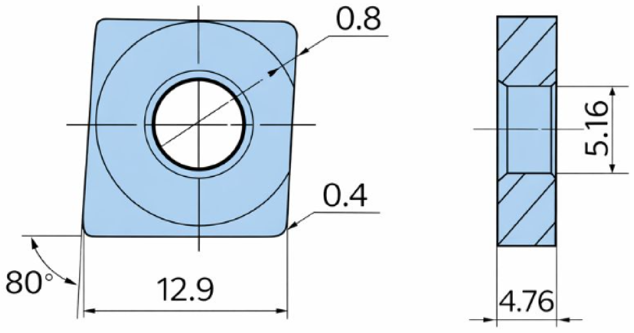
AISI 4340 alloy steel with a hardness of 50 ± 2 HRC was used in the form of cylindrical bars having a diameter of 60 mm and a length of 120 mm. All experiments were conducted on a CNC lathe machine, and the cutting operations were performed using G-code commands. The mechanical properties and chemical composition of the hardened steel are summarized in Table 1. PVD-coated aluminum nitride (AlN) TiCN-based cermet insert is employed as the cutting tool in this study. According to Sumitomo Electric [19], cermet tools are composed of a titanium carbonitride (TiCN)-based hard phase sintered with a metallic binder phase, which provides high wear resistance and adequate fracture toughness for finishing applications. The insert possessed a coating thickness of 3 µm, a hardness of 92 HRA, and a transverse rupture strength of 2.2 GPa. According to literature, TiCN-based cermet tools primarily consist of titanium carbonitride (TiCN) as the main hard phase, enriched with Ti, Nb, W, C, and N, which contribute to high hardness and wear resistance. In addition, W and Co are present as binder and secondary hard phases, providing improved toughness, thermal stability, and mechanical integrity during machining operations [20]. These inserts have a diamond shape with a tool nose radius of 0.4 mm. The geometry of cutting inserts is shown in Figure 1.
The experiments were carried out under two different machining environments—dry and minimum quantity lubrication (MQL)—at a cutting speed of 200 m/min, a feed rate of 0.1 mm/rev, and a depth of cut of 0.1 mm. Dry machining was performed in the absence of coolant or lubricant. For MQL setup, an external nozzle carrying the atomized mist at a flow rate of 60 mL/h at 6 bar pressure is projected to the cutting zone through the rake face of the tool. A commercially available flexible spray nozzle of 3 mm diameter with a conical tip was used to deliver the lubricant. The nozzle was positioned at a distance of 30 mm and at an angle of 45° with respect to the cutting edge based on previous studies [7,22,23] on hardened steel. The MQL system employed a UNIST Coolube 2210XP, supplied by UNIST Grand Rapids, Michigan, USA, a bio-based, vegetable-derived cutting fluid with low viscosity and a high flash point exceeding 200 °C, which provides enhanced wettability suitable for metal cutting processes.
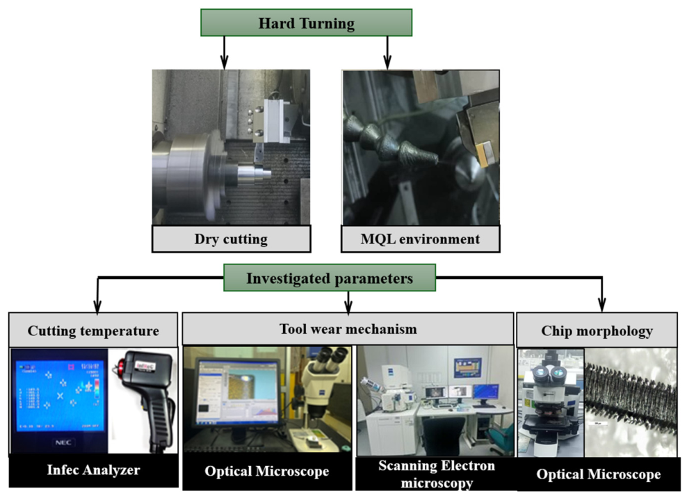
The output variables were assessed through both quantitative and qualitative analyses. Tool life was evaluated in accordance with the flank wear criterion defined as per ISO 3685, where tool life was determined when the average flank wear (Vbavg) reached 0.3 mm. Flank wear measurements were recorded at regular intervals every 40 mm of machining length to measure flank wear progression as a function of cutting time, which is important for establishing accurate wear evolution and tool life trends. This interval-based interruption is commonly adopted, as per previous literature [24,25], in tool wear and tool life studies to ensure reliable monitoring of wear development and to identify the point at which the ISO tool life criterion is reached. Flank wear is measured using an optical microscope (Zeiss, Oberkochen, Germany), integrated with ZEISS software (ZEN 2012 SP2) to monitor wear width and to examine tool wear progression under dry and MQL machining conditions. Cutting temperature measurements were obtained periodically during the machining trials using a thermal camera G 120 produced by Nippon Avionics Co., Ltd capable of capturing the maximum temperature of a moving surface and continuously recording thermal data throughout the machining process. To minimize measurement errors and ensure reliable temperature readings, the captured thermal images were analyzed frame by frame using the InfReC Analyzer NS 95000 analyzer (Ver.7.1D) software. The average of the maximum temperature readings extracted from the recorded frames was taken as the representative value for each cutting condition. An emissivity value of 0.1, based on the workpiece material, was used for temperature evaluation. Following completion of the experiments, qualitative analyses were performed to examine wear mechanisms using field emission scanning electron microscopy (FESEM) combined with energy-dispersive X-ray spectroscopy (EDX). In addition, chips formed during machining were examined using an Olympus BX51M optical microscope by (Olympus Corporation, Tokyo, Japan) to obtain high-resolution images. These observations complemented the quantitative measurements and aided in understanding the tribological interactions at the tool–chip and tool–workpiece interfaces. The overall research methodology adopted in this study is presented in Figure 2.

3. Results and Discussion

3.1. Tool Life and Tool Wear Mechanisms

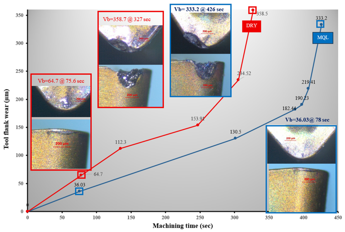
Figure 3 shows the influence of machining time on the average flank wear width of cermet tools when turning at a cutting speed of 200 m/min, a feed rate of 0.1 mm/rev, and a depth of cut of 0.1 mm. It can be seen that dry cutting exhibits a steeper wear progression curve, indicating a rapid transition from initial wear to severe flank wear. In contrast, the MQL environment shows a delayed and more gradual wear evolution, resulting in a longer tool life of 426 s, which is 30.27% higher compared to dry cutting. The reduced performance of a dry environment is consistent with the literature, as machining in the absence of any lubrication media is associated with accelerated wear due to high frictional effects and thermo-mechanical loads at the tool–chip and tool–workpiece interfaces. On the contrary, MQL suppressed these effects through an effective latent heat of evaporation mechanism [26]. The tool life obtained in the present study under MQL conditions at V = 200 m/min, f = 0.1 mm/rev, and doc = 0.1 mm was 426 s. For reference-based contextual comparison, this value is substantially higher than the tool life values reported in the available literature under similar cutting speed and feed conditions during hard turning of the same work material using TiAlN-coated carbide tools. For instance, Arun Kumar et al. [27] reported tool life values of 78 s and 174.6 s under flood cooling and cryogenic cutting, respectively. The MQL strategy adopted in the present study demonstrated an improvement of approximately 446% over flood cooling and 144% over cryogenic cutting, further confirming the effectiveness and feasibility of MQL as a sustainable alternative cooling and lubrication strategy.
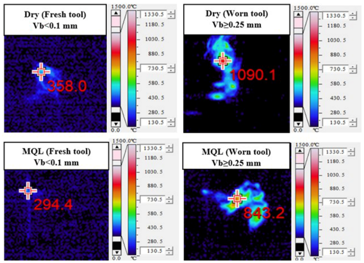
During the early stages of machining, when the tool first interacts with the workpiece, the hard carbides present in the microstructure of AISI 4340 produce a grinding-like effect, deteriorate the tool coating, and activate the abrasion wear mechanism [22]. With continued cutting, the wear enters a stable stage, during which it progresses steadily. However, in this stage, repeated cutting cycles completely remove the tool coating and eventually expose the tool substrate. Upon the removal of the protective layer, the tool can no longer withstand the harsh machining conditions and enters the rapid wear stage, at which the tool life criterion is reached [28]. In the absence of coolant and lubrication, high heat accumulates at the deformation zone, while the application of MQL significantly reduces the tool–chip interface temperature due to its lubricating properties; consequently, the friction between the contact interfaces is also reduced. However, with progressing machining, the cutting temperature increased with increasing tool wear. As evident from Figure 4, images captured from the thermal camera showed a significant increment in chip temperature in both environments. The thermal load increases as the cutting edge wears, resulting in higher friction and tool vibration [29].
During the early stages of tool wear when Vb < 100 µm, the tool wear image after machining for 78 s has shown minimal flank wear (36.03 µm) width and no significant crater wear formation with MQL environment. However, as the machining progressed into the steady-state wear stage, the flank wear increased, reaching 182.4 µm under MQL, while the dry cutting showed accelerating wear and reached 153.91 µm at 246.8 s. At the final stage, when the tool approaches the tool life criterion Vb ≈ 300 µm, a clear contrast in wear severity is evident between the two environments. Under dry cutting, the tool reaches Vb = 358.7 µm after a machining time of 327 s, whereas under MQL, the corresponding wear of Vb = 333.2 µm occurs later, at approximately 426 s, indicating extended tool life. The micrographs at this stage clearly signify that the cutting edge is severely degraded with a large flank wear land and signs of possible micro-chipping under dry conditions. The rake face also exhibits substantial material adhesion and increased crater width, reflecting excessive thermal exposure and unstable cutting conditions in the case of a dry environment. In contrast, MQL displays a comparatively smoother and more uniform flank-wear land, with maintained edge geometry.
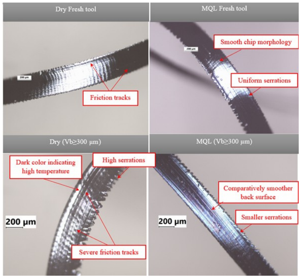
These arguments can also be supported from the optical microscopic images of chip morphology in Figure 4, which clearly indicate intense feed marks at the back side of the chip formed under dry cutting, and these marks became more pronounced with high tool wear. Under both environments, a serrated type of chip is formed due to adiabatic shear instability. Burnt chip formed with non-uniform and highly serrated ends at Vb≈300 µm signifies dominating frictional effects in the case of a dry environment. Fractured chips with larger crack depth are also noticed at high tool wear state in case of dry condition, which indicates thermoplastic instability as a result of high machining heat. As reported by Danish et al. [30], deep cracks that form at the top portion, appearing to propagate toward the bottom side of the chip surface, are indicative of excessive friction at the tool rake face. On the contrary, MQL has shown comparatively smoother chip morphology with fewer friction tracks even at the later stages of tool wear.
The temperature measurements in Figure 5 directly support the wear trends observed in Figure 3 and Figure 4. Under dry conditions, the maximum recorded temperature increases sharply from approximately 358 °C with the fresh tool to about 1090 °C with the worn tool. This substantial temperature rise can be attributed to progressive flank wear, which enlarges the tool–workpiece contact area, intensifies rubbing and plowing actions, and increases frictional heat generation [31]. As tool wear advances, the worn cutting edge also loses its sharpness, promoting unstable chip flow and localized heat concentration near the cutting edge. In comparison, the MQL environment demonstrated lower cutting temperatures, 294 °C with a fresh tool and 843 °C with a worn tool. The reduced temperature range under MQL is primarily due to the formation of a lubricating oil film and the effective penetration of the oil–air mist into the cutting zone, which lowers the coefficient of friction at the chip–tool interface and improves chip evacuation [32]. These effects reduce heat generation and preserve the cutting-edge geometry of the cermet cutting edge.

3.2. Tool Wear Mechanisms

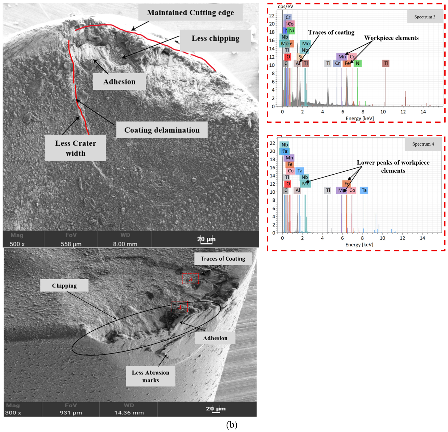
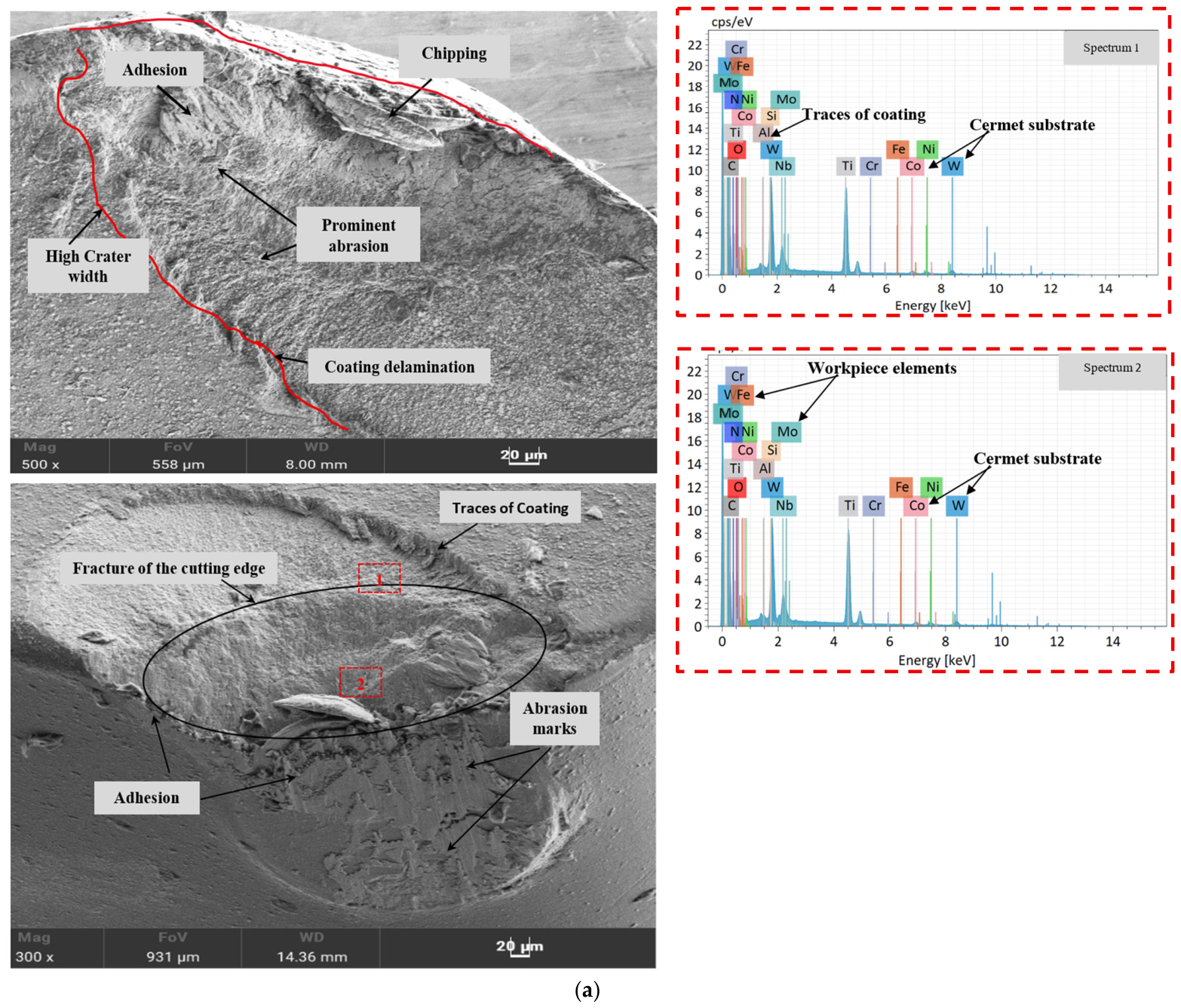
The study of tool wear mechanisms on both the rake and flank faces provides detailed information about the tool–workpiece interactions, chip–flow conditions, and influence of cooling and lubrication environments. In this study, tool wear investigations were conducted when the cutting insert reached the tool life criteria Vb = 300 µm under both dry and MQL environments. Figure 6 represents high-resolution FESEM images of the worn cermet inserts for both cutting conditions. It can be clearly seen that the tool damage under dry cutting is more pronounced than MQL. The greater crater area observed for dry cutting indicates an increased tool–chip contact length in the absence of lubrication.
With continued machining, hard inclusions in the microstructure of AISI 4340 alloy steel and prolonged chip contact cause coating delamination. Evidence of coating delamination can be noticed on the rake faces of tools. Reis et al. [33] explained that the stick–slip cycle of the chip during machining promotes adhesion and diffusion, eventually facilitating crater formation. On the contrary, worn tool morphology under MQL environment exhibits moderate crater area, less abrasion, and better-preserved cutting-edge geometry. These improvements are attributed to enhanced lubrication at the rake face, which reduces the coefficient of friction and promotes more favorable chip formation, favorably reducing the chip stick–slip cycle [34]. The corresponding EDX spectra 1 and 3 support these findings. The highest peaks of workpiece elements such as Fe, Mo, Mn, and Cr indicate considerable material adhesion under dry cutting conditions. In addition, the strong peaks of Ti, W, and Co suggest progressive coating delamination followed by exposure of the underlying cermet substrate. Conversely, spectrum 3 shows a considerably lower detection of workpiece elements, especially Fe, together with appreciable Al peaks and the absence of significant cermet matrix and binder phase elements such as W, suggesting that the coating remained largely intact, thereby resulting in reduced wear severity under MQL conditions.
It has also been noticed that parallel groove marks are apparent on the rake and flank faces of both tools, which are indicative of abrasive wear mechanisms, as during cutting, the tool material has been removed by mechanical action, producing such grooves. Strong peaks of W, Ti, Nb, and Co in spectra 2 and 4 near the cutting edge corroborate this observation. Significant material adhesion is also evident, being more pronounced in the dry condition. After the complete removal of the tool coating, the chemical affinity between Fe and Co increases as a result of chemical reactivity involving tungsten carbide with titanium and oxygen at high temperature. This promotes material adhesion [35]. Because the adhered material is relatively weakly bound, it can be dislodged during continued machining, removing substantial portions of the tool and leading to fracture or chipping. Significant chipping was also observed in a dry environment. On the contrary, MQL comparatively reduced the occurrence of tool chipping, resulting in comparatively lesser damage to the cutting edge due to its favorable heat dissipation and lubrication capabilities. Das et al. [36] reported that chipping in cermet tools occurs due to stress concentration and machine vibration issues. Overall, the micrographs indicate that MQL causes a comparatively maintained tool cutting edge, which is attributable to its superior heat-transfer and lubrication capabilities relative to dry machining [37].

3.3. Heat-Transfer Mechanism for Dry and MQL Environments

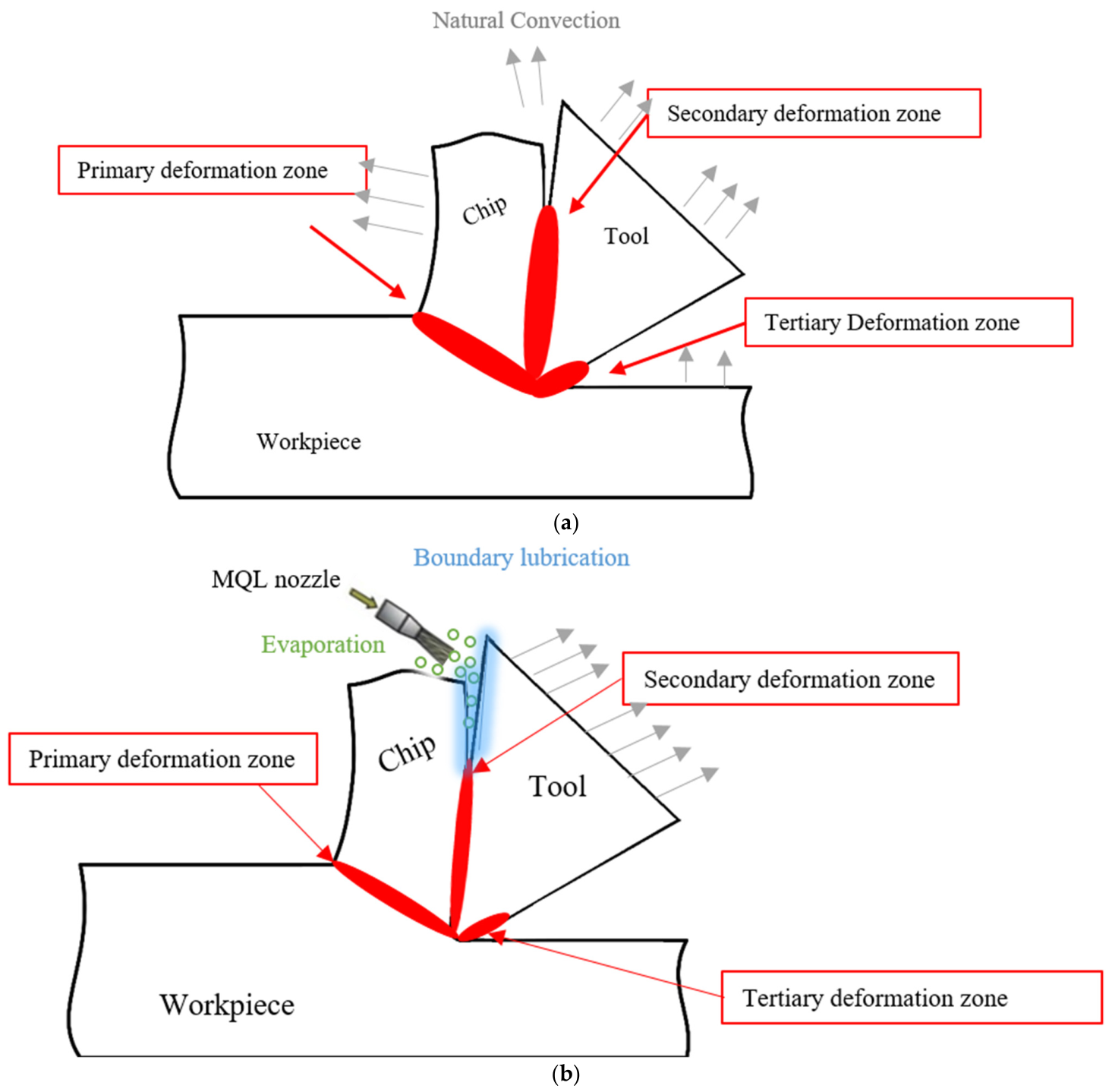
Figure 7 illustrates the heat-transfer mechanism and its influence on the deformation zone for both dry and MQL cutting conditions. Dry cutting in the absence of coolant or lubricant performed the heat dissipation mainly through natural convection. Part of the heat is conducted by the chip, tool, and workpiece. Consequently, the deformation zone becomes wider due to excessive heat accumulation at the tool–chip interface. In contrast, MQL provides effective cooling and lubrication by delivering a fine mist of lubricant directly to the rake face of the tool. This enhances heat removal through evaporation and convective heat-transfer mechanisms, thereby reducing the deformation zone, improving the chip formation, and minimizing the frictional effects at the contact interfaces.
The fine oil droplets under MQL carried by compressed air form a thin lubricating film at the tool–chip and tool–workpiece interfaces. This boundary film minimizes direct metal-to-metal contact, thereby reducing adhesive and abrasive wear. The oil film also lowers the coefficient of friction, resulting in smoother chip flow and decreased cutting forces.
  • The lubricant droplets absorb a portion of the generated heat and undergo partial evaporation at high-temperature zones. This phase change helps to dissipate thermal energy, thereby reducing the cutting temperature at the tool tip and preventing thermal softening and plastic deformation of the cutting edge [38].
  • The air–oil mixture also promotes convective heat transfer as the compressed air in the form of micro lubricant facilitates this function as the nozzle directed to the rake face cools the chip–tool interface [39].

4. Conclusions

The study investigated the tool wear mechanisms of cermet tools under dry and MQL environments to assess the cause of tool failure by incorporating in-depth analyses of cutting temperatures and chip morphology. The key findings of the investigation are summarized below:
  • The application of MQL, owing to its superior heat dissipation characteristics, resulted in a substantial increase in tool life of 30.27% compared to a dry environment. Tool wear progression exhibited a more stable and longer steady-state duration under an MQL environment, indicating improved cutting-edge stability. Dry cutting, on the other hand, showed rapidly increasing tool wear progression as a result of high machining heat and frictional effects in the absence of any lubrication medium.
  • Chip temperature measurements justified the tool wear morphology attained under both environments. The highest temperature is recorded under dry conditions, which increases sharply from 358 °C for the fresh tool to about 1090 °C for the worn tool. Under the MQL environment, the recoded temperature was in the range between 294 °C (fresh tool) and 843 °C (worn tool).
  • Analysis of chip morphology revealed serrated-type chip formation for both environments. The degree of serration increased with tool wear. Chips produced under dry cutting exhibited deep feed marks on the chip back surface, indicating severe friction at the tool–chip interface. In contrast, chips formed with an MQL environment exhibited smooth morphology and closely spaced saw-tooth patterns.
  • Tool wear mechanisms revealed that both environments were dominated by abrasion, adhesion, and chipping. In the absence of a lubrication medium, pronounced crater formation is noticed for dry cutting. While the application of MQL mist lowered the frictional effects, it consequently showed less crater formation, adhesion, and abrasion, and maintained cutting edge geometry.

Author Contributions

N.J.: methodology, writing—review and editing, supervision, and funding acquisition. S.Y.: methodology, investigation, data curation, and writing—original draft preparation. J.A.G.: methodology, investigation, data curation, writing—review and editing, and supervision. S.M.: methodology and writing—review and editing. All authors have read and agreed to the published version of the manuscript.

Funding

The authors extend their appreciation to Prince Sattam bin Abdulaziz University for funding this research work through the project number PSAU/2025/01/35490.

Data Availability Statement

All data are included in the paper. The raw data supporting the conclusions of this article will be made available by the authors on request.

Conflicts of Interest

The authors declare no conflicts of interest.

References

  1. Bag, R.; Panda, A.; Sahoo, A.K.; Kumar, R. A Perspective Review on Surface Integrity and Its Machining Behavior of AISI 4340 Hardened Alloy Steel. Mater. Today Proc. 2019, 18, 3532–3538. [Google Scholar] [CrossRef]
  2. Yaqoob, S.; Ghani, J.A.; Jouini, N.; Juri, A.Z.; Haron, C.H.C.; Muhamad, S.S. Promoting Resource Equity through the Systematic Literature Review in Analysing Cryo-Lubrication Techniques for Sustainable Machining Processes. Tribol. Int. 2025, 204, 110440. [Google Scholar] [CrossRef]
  3. Debnath, S.; Reddy, M.M.; Yi, Q.S. Environmental Friendly Cutting Fluids and Cooling Techniques in Machining: A Review. J. Clean. Prod. 2014, 83, 33–47. [Google Scholar] [CrossRef]
  4. Greeley, M.; Rajagopalan, N. Impact of Environmental Contaminants on Machining Properties of Metalworking Fluids. Tribol. Int. 2004, 37, 327–332. [Google Scholar] [CrossRef]
  5. Hoghoughi, M.H.; Farahnakian, M.; Elhami, S. Environmental, Economical, and Machinability Based Sustainability Assessment in Hybrid Machining Process Employing Tool Textures and Solid Lubricant. Sustain. Mater. Technol. 2022, 34, e00511. [Google Scholar] [CrossRef]
  6. Park, R.M. Risk Assessment for Metalworking Fluids and Cancer Outcomes. Am. J Ind. Med 2018, 61, 198–203. [Google Scholar] [CrossRef]
  7. Yaqoob, S.; Ghani, J.A.; Jouini, N.; Sheik Muhamad, S.; Che Haron, C.H.; Juri, A. High-Speed Turning of AISI 4340 Alloy Steel Using Carbide Tools in a Sustainable Minimum Quantity Lubrication Environment. Ind. Lubr. Tribol. 2024, 77, 708–722. [Google Scholar] [CrossRef]
  8. Mahboob Ali, M.A.; Azmi, A.I.; Mohd Zain, M.Z.; Murad, M.N.; Mohd Khalil, A.N.; Abd Rahim, M.S. New Bio-Based Nanolubricants for Turning of Inconel 718 towards Improvement of Tool Wear Resistance and Specific Cutting Energy. IOP Conf. Ser. Mater. Sci. Eng. 2019, 670, 012007. [Google Scholar] [CrossRef]
  9. Pereira, O.; Martín-Alfonso, J.E.; Rodríguez, A.; Calleja, A.; Fernández-Valdivielso, A.; López de Lacalle, L.N. Sustainability Analysis of Lubricant Oils for Minimum Quantity Lubrication Based on Their Tribo-Rheological Performance. J. Clean. Prod. 2017, 164, 1419–1429. [Google Scholar] [CrossRef]
  10. Abedrabbo, F.; Soriano, D.; Madariaga, A.; Fernández, R.; Abolghasem, S.; Arrazola, P.J. Experimental Evaluation and Surface Integrity Analysis of Cryogenic Coolants Approaches in the Cylindrical Plunge Grinding. Sci. Rep. 2021, 11, 20952. [Google Scholar] [CrossRef]
  11. Said, Z.; Gupta, M.; Hegab, H.; Arora, N.; Khan, A.M.; Jamil, M.; Bellos, E. A Comprehensive Review on Minimum Quantity Lubrication (MQL) in Machining Processes Using Nano-Cutting Fluids. Int. J. Adv. Manuf. Technol. 2019, 105, 2057–2086. [Google Scholar] [CrossRef]
  12. Roy, S.; Kumar, R.; Das, R.K.; Sahoo, A.K. A Comprehensive Review on Machinability Aspects in Hard Turning of AISI 4340 Steel. IOP Conf. Ser. Mater. Sci. Eng. 2018, 390, 012009. [Google Scholar] [CrossRef]
  13. Das, R.K.; Sahoo, A.K.; Mishra, P.C.; Kumar, R.; Panda, A. Comparative Machinability Performance of Heat Treated 4340 Steel under Dry and Minimum Quantity Lubrication Surroundings. Procedia Manuf. 2018, 20, 377–385. [Google Scholar] [CrossRef]
  14. Singh, R.; Dureja, J.S.; Dogra, M. Performance Evaluation of Textured Carbide Tools under Environment-Friendly Minimum Quantity Lubrication Turning Strategies. J. Braz. Soc. Mech. Sci. Eng. 2019, 41, 87. [Google Scholar] [CrossRef]
  15. Shalaby, M.; Veldhuis, S. New Observations on High-Speed Machining of Hardened AISI 4340 Steel Using Alumina-Based Ceramic Tools. J. Manuf. Mater. Process. 2018, 2, 27. [Google Scholar] [CrossRef]
  16. Zhang, Y.; Han, J.; Cao, S.; Song, X.; Yan, X.; Nie, F.; Peng, Z. Wear Behavior of Coated Cermet/Carbide Tools during High-Speed Turning of 18CrNiMo7-6 Steel and Its Associated Surface Integrity Evaluations. Wear 2025, 576–577, 206121. [CrossRef]
  17. Wagri, N.K.; Jain, N.K.; Petare, A.; Das, S.R.; Tharwan, M.Y.; Alansari, A.; Alqahtani, B.; Fattouh, M.; Elsheikh, A. Investigation on the Performance of Coated Carbide Tool during Dry Turning of AISI 4340 Alloy Steel. Materials 2023, 16, 668. [Google Scholar] [CrossRef]
  18. Mallick, R.; Kumar, R.; Panda, A.; Sahoo, A.K. Hard Turning Performance Investigation of AISI D2 Steel under a Dual Nozzle MQL Environment. Lubricants 2023, 11, 16. [Google Scholar] [CrossRef]
  19. Matsuda, K.; Sakamoto, A.; Hirose, K.; Fukui, H.; Yamagata, K. Exclusive Turning Cermet Grade “T1000A”. SEI Tech. Rev. 2014, 78, 87–89. [Google Scholar]
  20. Şirin, Ş. Investigation of the Performance of Cermet Tools in the Turning of Haynes 25 Superalloy under Gaseous N2 and Hybrid Nanofluid Cutting Environments. J. Manuf. Process. 2022, 76, 428–443. [Google Scholar] [CrossRef]
  21. Bag, R.; Panda, A.; Sahoo, A.K.; Kumar, R. Machinability Characteristics Analysis of Hard Turning Operation on AISI 4340 Steel Using Physical Vapor Deposition Multilayer Coated Carbide Cutting Tool in the Dry Environment. Proc. Inst. Mech. Eng. Part E J. Process Mech. Eng. 2023, 237, 2222–2233. [Google Scholar] [CrossRef]
  22. Ahmad, A.A.; Ghani, J.A.; Che Haron, C.H. Effect of Cutting Parameters on Tool Life during End Milling of AISI 4340 under MQL Condition. Ind. Lubr. Tribol. 2022, 74, 392–401. [Google Scholar] [CrossRef]
  23. Ghani, J.A.; Yaqoob, S.; Jouini, N.; Juri, A.Z.; Haron, C.H.C.; Muhamad, S.S. Performance Evaluation of Multilayer Coated Carbide Tools in Machining Hardened AISI430 at High Cutting Speed under Minimum Quantity Lubrication. J. Tribol. 2024, 42, 146–160. [Google Scholar]
  24. Alhadeff, L.L.; Marshall, M.B.; Curtis, D.T.; Slatter, T. Protocol for Tool Wear Measurement in Micro-Milling. Wear 2019, 420–421, 54–67. [Google Scholar] [CrossRef]
  25. D’Addona, D.M.; Ullah, A.M.M.S.; Matarazzo, D. Tool-Wear Prediction and Pattern-Recognition Using Artificial Neural Network and DNA-Based Computing. J. Intell. Manuf. 2017, 28, 1285–1301. [Google Scholar] [CrossRef]
  26. Sahoo, A.K.; Kumar, R.; Panda, A.; Mishra, P.C.; Mohanty, T. Assessment of Sustainable Dry and MQL-Assisted Hard Machining Using MTCVD Multilayered Coated Carbide (TiN/TiCN/Al2O3) Insert: Évaluation de l’usinage Dur Durable à Sec et Assisté Par MQL à l’aide d’une Pastille En Carbure à Revêtement Multicouche (TiN/TiCN/Al2O3) MTCVD. Can. Metall. Q. 2023, 62, 651–664. [Google Scholar] [CrossRef]
  27. Arun Kumar, S.; Yoganath, V.G.; Krishna, P. Machinability of Hardened Alloy Steel Using Cryogenic Machining. Mater. Today Proc. 2018, 5, 8159–8167. [Google Scholar] [CrossRef]
  28. Jouini, N.; Yaqoob, S.; Ghani, J.A. Investigations on the Machinability Performance of Al2 O3/TiCN CVD Coated Carbide Tools in Sustainable High-Speed Hard-Turning of AISI 4340 Alloy Steel. Mater. Res. Express 2024, 11, 096509. [Google Scholar] [CrossRef]
  29. Li, S.; Li, S.; Hu, Y.; Popov, E. Experimental Study on Coupling Characteristics of Cutting Temperature Rise and Cutting Vibration under Different Tool Wear States. Int. J. Adv. Manuf. Technol. 2022, 118, 907–919. [Google Scholar] [CrossRef]
  30. Danish, M.; Gupta, M.K.; Rubaiee, S.; Ahmed, A.; Korkmaz, M.E. Influence of Hybrid Cryo-MQL Lubri-Cooling Strategy on the Machining and Tribological Characteristics of Inconel 718. Tribol. Int. 2021, 163, 107178. [Google Scholar] [CrossRef]
  31. Jafarian Zenjanab, M.; Pedrammehr, S.; Chalak Qazani, M.R.; Shabgard, M.R. Influence of Cutting Fluid-Based CuO-Nanofluid with Boric Acid-Nanoparticles Additives on Machining Performances of AISI 4340 Tool Steel in High-Speed Turning Operation. Iran. J. Sci. Technol. Trans. Mech. Eng. 2022, 46, 335–345. [Google Scholar] [CrossRef]
  32. Bag, R.; Panda, A.; Sahoo, A.K.; Kumar, R. Performance Analysis of AISI 4340 Hardened Steel in Dual Jet MQL Turning System: A Comparison Study Between CVD and PVD-Coated Carbide Tools. Surf. Rev. Lett. 2024, 2550031. [Google Scholar] [CrossRef]
  33. Reis, B.C.M.; Dos Santos, A.J.; Dos Santos, N.F.P.; Câmara, M.A.; De Faria, P.E.; Abrão, A.M. Cutting Performance and Wear Behavior of Coated Cermet and Coated Carbide Tools When Turning AISI 4340 Steel. Int. J. Adv. Manuf. Technol. 2019, 105, 1655–1663. [Google Scholar] [CrossRef]
  34. Araújo Junior, A.S.; Sales, W.F.; Da Silva, R.B.; Costa, E.S.; Rocha Machado, Á. Lubri-Cooling and Tribological Behavior of Vegetable Oils during Milling of AISI 1045 Steel Focusing on Sustainable Manufacturing. J. Clean. Prod. 2017, 156, 635–647. [Google Scholar] [CrossRef]
  35. Chen, X.; Xu, J.; Xiao, Q. Cutting Performance and Wear Characteristics of Ti(C,N)-Based Cermet Tool in Machining Hardened Steel. Int. J. Refract. Met. Hard Mater. 2015, 52, 143–150. [Google Scholar] [CrossRef]
  36. Das, A.; Mukhopadhyay, A.; Patel, S.K.; Biswal, B.B. Comparative Assessment on Machinability Aspects of AISI 4340 Alloy Steel Using Uncoated Carbide and Coated Cermet Inserts During Hard Turning. Arab. J. Sci. Eng. 2016, 41, 4531–4552. [Google Scholar] [CrossRef]
  37. Gupta, M.K.; Niesłony, P.; Sarikaya, M.; Korkmaz, M.E.; Kuntoğlu, M.; Królczyk, G.M.; Jamil, M. Tool Wear Patterns and Their Promoting Mechanisms in Hybrid Cooling Assisted Machining of Titanium Ti-3Al-2.5V/Grade 9 Alloy. Tribol. Int. 2022, 174, 107773. [Google Scholar] [CrossRef]
  38. Liu, M.; Li, C.; Zhang, Y.; An, Q.; Yang, M.; Gao, T.; Mao, C.; Liu, B.; Cao, H.; Xu, X.; et al. Cryogenic Minimum Quantity Lubrication Machining: From Mechanism to Application. Front. Mech. Eng. 2021, 16, 649–697. [Google Scholar] [CrossRef]
  39. Shi, Y.; Zheng, J.; Peng, C.; Guo, L.; Shi, W.; Feng, P.; Zhao, R. An Investigation into the Impact of Tool Surface Texture on the Cutting Property of Nickel-Based Superalloys under MQL Conditions. Int. J. Adv. Manuf. Technol. 2025, 139, 6157–6172. [Google Scholar] [CrossRef]
Figure 1. Schematics of the insert geometry used for conducting experiments.
Processes 14 01378 g001
Figure 2. Research methodology adopted for investigations.
Processes 14 01378 g002
Figure 3. Wear progression graph versus machining time under dry and MQL environment.
Processes 14 01378 g003
Figure 4. Chip formation for different tool wear states for dry and MQL environments.
Processes 14 01378 g004
Figure 5. Temperature measurements for different tool wear states for dry and MQL environments.
Processes 14 01378 g005
Figure 6. FESEM and EDX images for (a) dry and (b) MQL environments.
Processes 14 01378 g006aProcesses 14 01378 g006b
Figure 7. Heat-transfer mechanism and its influence on the deformation zone under (a) dry cutting, (b) MQL environment.
Processes 14 01378 g007
Table 1. Mechanical properties and elemental composition of AISI 4340.
Mechanical Properties [21]Chemical Composition
PropertiesValuesElementsComposition
Tensile strength1550 N/mm2C0.39
Density7850 kg/m3Mn0.71
Hardness50 HRCMo0.22
Modulus of elasticity205 KN/mm2Si0.26
Poisson ratio0.30Ni1.73
Conductivity44.5 W/m °CCr0.80
Specific heat475 J/Kg °CS0.006
Expansion0.13 m/m °C (10−6)FeBalance
Disclaimer/Publisher’s Note: The statements, opinions and data contained in all publications are solely those of the individual author(s) and contributor(s) and not of MDPI and/or the editor(s). MDPI and/or the editor(s) disclaim responsibility for any injury to people or property resulting from any ideas, methods, instructions or products referred to in the content.