Review

Advances and Challenges in Ice Accretion on Passive Icephobic Surfaces


Department of Mechanical, Industrial and Aerospace Engineering, Concordia University, 1455 De Maisonneuve Blvd. W., Montreal, QC H3G 1M8, Canada
*
Author to whom correspondence should be addressed.
Processes 2026, 14(6), 985; https://doi.org/10.3390/pr14060985
Submission received: 24 November 2025 / Revised: 26 February 2026 / Accepted: 5 March 2026 / Published: 19 March 2026

Abstract

Ice accretion on aircraft, wind-turbine blades, power networks, civil infrastructure, and exposed sensors poses severe safety risks and economic costs. Passive icephobic surfaces mitigate icing by delaying heterogeneous nucleation, altering droplet impact/solidification and wetting transitions, and/or weakening the ice–substrate bond so that accreted ice sheds under modest aerodynamic, gravitational, or vibrational loads. This review synthesizes recent progress using a unified mechanism framework linking (i) nucleation and early freezing, (ii) droplet dynamics during impact or condensation/frosting, and (iii) ice accretion and removal governed by interfacial fracture. Smooth low-surface-energy coatings, textured (superhydrophobic) surfaces, slippery liquid-infused porous surfaces (SLIPS), and low-interfacial-toughness strategies are critically compared in terms of achievable performance ranges, failure modes, durability limits, fabrication scalability, and test-method dependence. Ice-adhesion measurement approaches (push-off, pull-off/tensile, centrifugal) are assessed and a minimum reporting checklist is provided to improve comparability. Case studies across aviation, wind energy, power infrastructure, sensors, and emerging civil-engineering coatings highlight that durability and scale-dependent failure modes remain the dominant barriers to durable, energy-free icing mitigation. The review concludes with priorities for eco-friendly chemistries, self-healing or renewable layers, standardized testing/reporting, and data-driven (machine learning-assisted) optimization to accelerate translation into durable passive ice-mitigation technologies.

1. Introduction

Ice accumulation on exposed surfaces is a pervasive hazard across multiple sectors, with significant safety implications and economic losses [1]. In aerospace, ice accretion on wings, inlets, and engines degrades aerodynamic performance and has contributed to incidents and accidents [2,3]. In the energy sector, ice build-up on wind-turbine blades reduces power output and can induce hazardous imbalance, while icing on overhead lines and structures leads to outages and mechanical failures [4,5,6,7]. Transportation infrastructure and telecommunications likewise experience ice-related degradation and downtime [8]. Although chemical de-icers, electric heating, and mechanical removal are widely used, these active methods are energy-intensive, environmentally burdensome, and typically provide only temporary relief [9]. These limitations motivate passive icephobic surfaces, namely materials that delay the onset of freezing and/or exhibit extremely low ice-adhesion strength so that any ice that does form can be shed with minimal force [10,11].
As summarized in Figure 1, passive surface strategies can be broadly categorized as: (i) smooth, low-surface-energy coatings; (ii) textured surfaces, including superhydrophobic designs that minimize solid–liquid contact; (iii) slippery liquid-infused porous surfaces (SLIPS); and (iv) sub-surface textured or architected substrates. Superhydrophobicity remains attractive for reducing real contact area and promoting droplet mobility [12], while engineered roughness/topography is the most extensively exploited lever for controlling wetting, nucleation pathways, and interfacial adhesion [13].
To ensure coverage that is both comprehensive and current, this review focuses on passive icephobic surfaces and coatings, i.e., surface/material strategies intended to reduce ice nucleation, accretion, or adhesion without requiring continuous external energy input. Studies were collected from major scholarly databases (Web of Science, Scopus, and Google Scholar) using combinations of the following keywords: icephobic, ice adhesion, anti-icing, droplet freezing, SLIPS, superhydrophobic, elastomer, lubricant-infused, photothermal, laser texturing, centrifuge adhesion test, and icing wind tunnel. Priority was given to peer-reviewed studies published between 2010 and 2026 that report quantitative metrics (e.g., ice-adhesion strength, icing delay/freezing time, shedding thresholds, or durability under cycles). Purely active de-icing concepts were excluded, except where needed as performance benchmarks or to contextualize hybrid strategies.
Designing surfaces that are truly icephobic is challenging because ice adhesion emerges from coupled interfacial phenomena, including wetting state (Cassie vs. Wenzel), contact-line pinning, impact/solidification dynamics, and interfacial fracture. This review synthesizes the state of the art with an emphasis on the mechanisms that link surface chemistry and topography to icing behavior and adhesion strength. Section 2 reviews the fundamentals of ice formation and adhesion, from nucleation thermodynamics to droplet impact and wetting models. Section 3 examines how micro/nano-scale and hierarchical roughness govern wettability, pinning, and adhesion. Section 4 compares ice-adhesion measurement methods (shear/push-off, tensile/pull-off, and centrifugal), highlighting artifacts and the need for standardized protocols. Section 5 surveys fabrication approaches (top-down texturing vs. bottom-up coatings) and scale-up/durability considerations. Section 6 discusses low-interfacial-toughness strategies, including soft elastomeric films and SLIPS, that enable ultra-low adhesion and size-independent de-bonding. Section 7 presents application case studies (aircraft, wind turbines, power infrastructure, and sensors). Section 8 outlines cross-cutting challenges (durability, environmental considerations, standardization) and opportunities, including data-driven surface design, followed by Section 9 with concluding remarks.

2. Fundamentals of Ice Accretion and Adhesion

Ice formation on engineered surfaces is governed by interfacial thermodynamics, unsteady fluid and heat transfer during droplet impact, and the wetting state set by surface chemistry and topography. This section summarizes key concepts needed to interpret the performance of icephobic materials in subsequent sections.

2.1. Thermodynamics of Nucleation

In pure water, homogeneous nucleation of ice requires substantial supercooling, typically to about 35 to 40   ° C , to overcome the free energy barrier associated with creating a critical nucleus. The classical expression for the barrier to homogeneous nucleation is
Δ G hom * = 16 π γ s l 3 3 Δ G v 2 ,
where γ s l is the solid–liquid interfacial energy and Δ G v is the volumetric free energy difference between ice and water at the given supercooling.
Most practical icing scenarios involve heterogeneous nucleation catalyzed by a substrate or impurities, which lowers the barrier by a geometric factor f ( θ ) that depends on the equilibrium contact angle θ of an ice nucleus on the surface:
Δ G het * = f ( θ ) Δ G hom * , 0 < f ( θ ) 1 ,
with the classical spherical-cap factor on an ideal smooth surface given by [15]
f ( θ ) = 2 3 cos θ + cos 3 θ 4 .
Hydrophilic surfaces (small θ ) strongly reduce the barrier and promote early ice nucleation, whereas hydrophobic surfaces (large θ ) inhibit nucleation by keeping the incipient nucleus from wetting the substrate. This thermodynamic effect delays the onset of freezing but does not, by itself, determine the eventual strength of the ice–substrate bond once solidification proceeds.

2.2. Droplet Impact and Solidification Dynamics

In many applications (aircraft in flight, wind turbines), supercooled droplets impinge on surfaces and either rebound, spread, or freeze during the brief contact time. The outcome is governed by inertia, viscosity, capillarity, and heat transfer, which are conveniently expressed using the dimensionless groups
W e = ρ V 2 D γ , R e = ρ V D μ , S t e = c p Δ T L f ,
where ρ is the liquid density, V the impact velocity, D the droplet diameter, γ the surface tension, μ the dynamic viscosity, c p the specific heat, Δ T the degree of supercooling relative to the melting temperature, and L f the latent heat of fusion.
Physically, W e measures inertial versus capillary forces and R e measures inertial versus viscous forces; increasing W e promotes spreading and possible splashing, whereas low W e favors compact shapes or rebound on non-wetting surfaces. The Stefan number S t e compares sensible to latent heat; larger S t e indicates that freezing during contact is more likely.
Low-hysteresis hydrophobic or superhydrophobic surfaces reduce liquid residence time by promoting recoil, rebound, or roll-off, which can prevent freezing if the solidification time exceeds the contact time. On sufficiently cold substrates, however, contact freezing can occur at the initial liquid–solid contact, anchoring the droplet before it can detach. Surface texture influences these pathways: if capillary pressure forces liquid into the texture (Wenzel wetting), the benefit of non-wetting is lost and solidifying water can mechanically interlock with asperities. Thermal properties also matter. Higher Ste (more sensible heat relative to latent heat) generally lengthens the time to full solidification and increases the chance of shedding before a strong bond develops. Under harsh icing fluxes or very low ambient temperatures, some accretion is expected even on optimized non-wetting surfaces, shifting the design target from anti-icing toward low-adhesion de-icing.

2.3. Wetting Models and Wetting Transitions

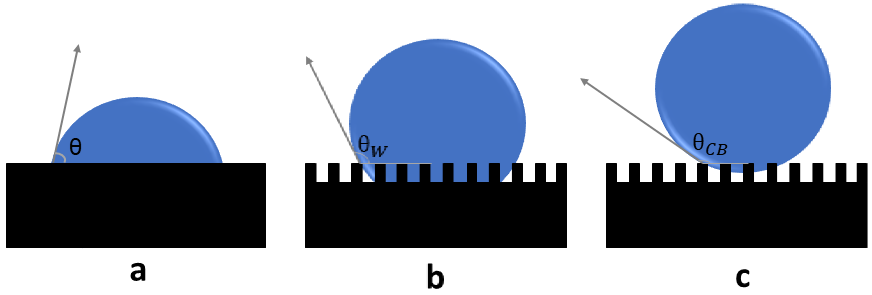
Apparent wetting on rough surfaces is commonly described by the Wenzel and Cassie–Baxter models (Figure 2). In the Wenzel state, liquid fully penetrates the texture and the apparent contact angle θ * follows
cos θ * = r cos θ 0 ,
where θ 0 is the intrinsic contact angle on the smooth material and r is the roughness factor (ratio of true to projected area). Roughness amplifies intrinsic wetting: hydrophilic materials become more hydrophilic and hydrophobic materials more hydrophobic.
In the Cassie–Baxter state, liquid rests on asperity tops while air remains trapped beneath, yielding a composite interface:
cos θ * = ϕ s cos θ 0 1 ϕ s ,
where ϕ s is the solid fraction in contact with the liquid. For ϕ s 1 , very high apparent contact angles and very low hysteresis are possible, which minimize the real contact area and can lower ice adhesion if freezing occurs.
Additionally, in this review, superhydrophobicity is treated as a wetting-state classification based on liquid-water metrics (static contact angle, contact-angle hysteresis, and roll-off/sliding angle), whereas icephobicity is defined functionally by reduced ice nucleation/accretion and/or reduced ice adhesion under specified icing conditions [8]. Superhydrophobicity can reduce droplet residence time and apparent contact area; however, it is neither necessary nor sufficient for icephobicity [14,16,17].
Wetting transitions from Cassie to Wenzel may be induced by impact pressure, prolonged exposure to liquid water, condensation and frosting, or by the advancing ice front during solidification. Once liquid or ice penetrates the texture, mechanical interlocking and contact-line pinning increase interfacial toughness and adhesion. Accordingly, robust icephobic designs combine low surface energy with textures that resist impalement and preserve a composite interface during both liquid contact and freezing [18]. Hierarchical micro- and nano-scale features are often used to stabilize non-wetting states and to limit frost bridging across the texture, thereby reducing the likelihood of strong interlocks forming during accretion. Therefore, a unified way to interpret icing mitigation is to view icing as a coupled problem: (i) heterogeneous nucleation and early ice growth, (ii) droplet impact/spreading/recalescence and wetting transitions during dynamic freezing or condensation/frosting, and (iii) accretion and removal governed by interfacial fracture.

3. Surface Topography, Wettability, and Ice Adhesion

Surface topography and surface chemistry jointly determine wetting state, contact-line mobility, and the extent of mechanical interlocking, and therefore they play a central role in controlling ice adhesion. Roughness can either suppress or enhance adhesion depending on length scale, morphology, and whether the texture remains in a Cassie-like or Wenzel-like state during icing [1,12,14]. This section reviews how single-scale and hierarchical textures affect wetting and ice adhesion, how roughness statistics relate to performance, and how these factors connect mechanically to the work of adhesion and interfacial toughness.

3.1. Single-Scale Micro- and Nano-Roughness

Single-scale roughness at the micro- or nano-scale strongly affects both wetting and ice adhesion. Early icephobic work focused on micro-rough or nanoparticle-based coatings that rendered inherently hydrophobic substrates superhydrophobic, achieving water contact angles above 150 ° with low hysteresis and thereby reducing the real solid–liquid contact area [1,4,19]. For instance, Menini and Farzaneh showed that rough polymer and composite coatings on aluminum could reduce shear ice-adhesion strength by factors of two to four compared to bare metal, provided that low hysteresis and a Cassie-like wetting state were maintained [19].
However, a high static water contact angle alone is insufficient for robust icephobicity. Kulinich and Farzaneh demonstrated that rough fluoropolymer coatings with high static contact angles but large contact-angle hysteresis did not perform well: only coatings that were both superhydrophobic and harbored low-hysteresis showed substantial reductions in τ ice [20]. These results underscore that contact-line pinning, captured by hysteresis or receding angle, is as important as the apparent contact angle itself [14,19,20].
Single-scale micro-textures (e.g., micropillars, microgrooves) may still permit liquid ingress if the pitch or geometry allows, enabling anchoring of liquid or ice within the texture. Purely nanostructured films, such as dense nanoparticle layers, can be overwhelmed by condensation or frost, as small pores readily fill by capillary action, converting a Cassie state to Wenzel and greatly increasing adhesion [12,16]. Systematic studies that vary feature size and spacing indicate an optimal texture that is sparse enough to minimize solid–liquid contact (favoring Cassie) yet not so sparse that liquid sags and penetrates under hydrostatic or impact pressure [21]. If roughness is too coarse (feature size comparable to ice thickness), ice can key into the asperities; if too fine and fully frosted, the texture effectively behaves as a rough, fully wetted solid. Roughness alone is therefore not a panacea; it must be combined with low surface energy and careful control of pinning to avoid unintended Wenzel states during freezing [14,20]. Apparent contradictions in the literature on micro/nano-textured icephobic surfaces largely arise because performance depends on the dominant icing pathway. Under dry impact icing, textures that maintain low-hysteresis in a Cassie-like state can reduce residence time and effective contact area, lowering the probability of freezing-on-impact and/or lowering apparent adhesion. Under frosting/condensation-driven icing, pores can fill and frost can bridge asperities, converting the interface toward a Wenzel-like, mechanically interlocked state and increasing adhesion and variability (Equation (6)). These pathway-dependent transitions, combined with wear-induced texture degradation, explain why a high static contact angle alone does not guarantee durable icephobicity and why cross-study comparisons must be interpreted in light of protocol details and durability conditioning [14,16,17].

3.2. Hierarchical (Dual-Scale) Structures

Natural non-wetting surfaces such as lotus leaves and certain insect wings often exhibit hierarchical structures: micro-scale features decorated with nano-scale textures. Such dual-scale roughness stabilizes non-wetting states and improves robustness against external perturbations. In icephobic design, hierarchical architectures reduce the contact area through the micro-scale features while the nano-scale texture helps resist liquid impalement and limits pinning of both water and ice [1,12].
Dual- or triple-scale coatings can yield water contact angles above 160 ° with very low sliding angles, delaying icing under condensing/frosting conditions and reducing adhesion when ice does form [21,22]. Nguyen et al. showed that superhydrophobic surfaces with optimized dual-scale roughness significantly delayed frost formation and reduced ice adhesion compared with single-scale textures [21]. Zhang et al. similarly reported hierarchical nanostructures on aluminum that promoted controlled condensation and delayed icing, highlighting the advantage of multi-scale textures under realistic atmospheric conditions [22]. In addition, hierarchical designs can resist frost bridging by limiting the formation of continuous ice layers and interrupting frost-front propagation across the surface [14,16].

3.3. Roughness Metrics, Surface Statistics, and Ice Adhesion

Quantitative roughness metrics help correlate structure with performance. Common 2D parameters include the mean arithmetic roughness R a and root-mean-square roughness R q , while 3D profilometry yields areal measures such as S a , S q , and the developed interfacial area ratio S d r (percentage increase in true area relative to projected area). Fractal dimension D f describes multi-scale roughness, ranging from D f = 2 for ideally smooth surfaces to values approaching 3 for extremely rough, multi-scale topographies [14,16]. Increased S d r or true contact area often correlates with higher adhesion if the surface is fully wetted, whereas certain geometries (e.g., rounded or re-entrant asperities) may sustain a composite interface and lower adhesion even at relatively high S d r [14].
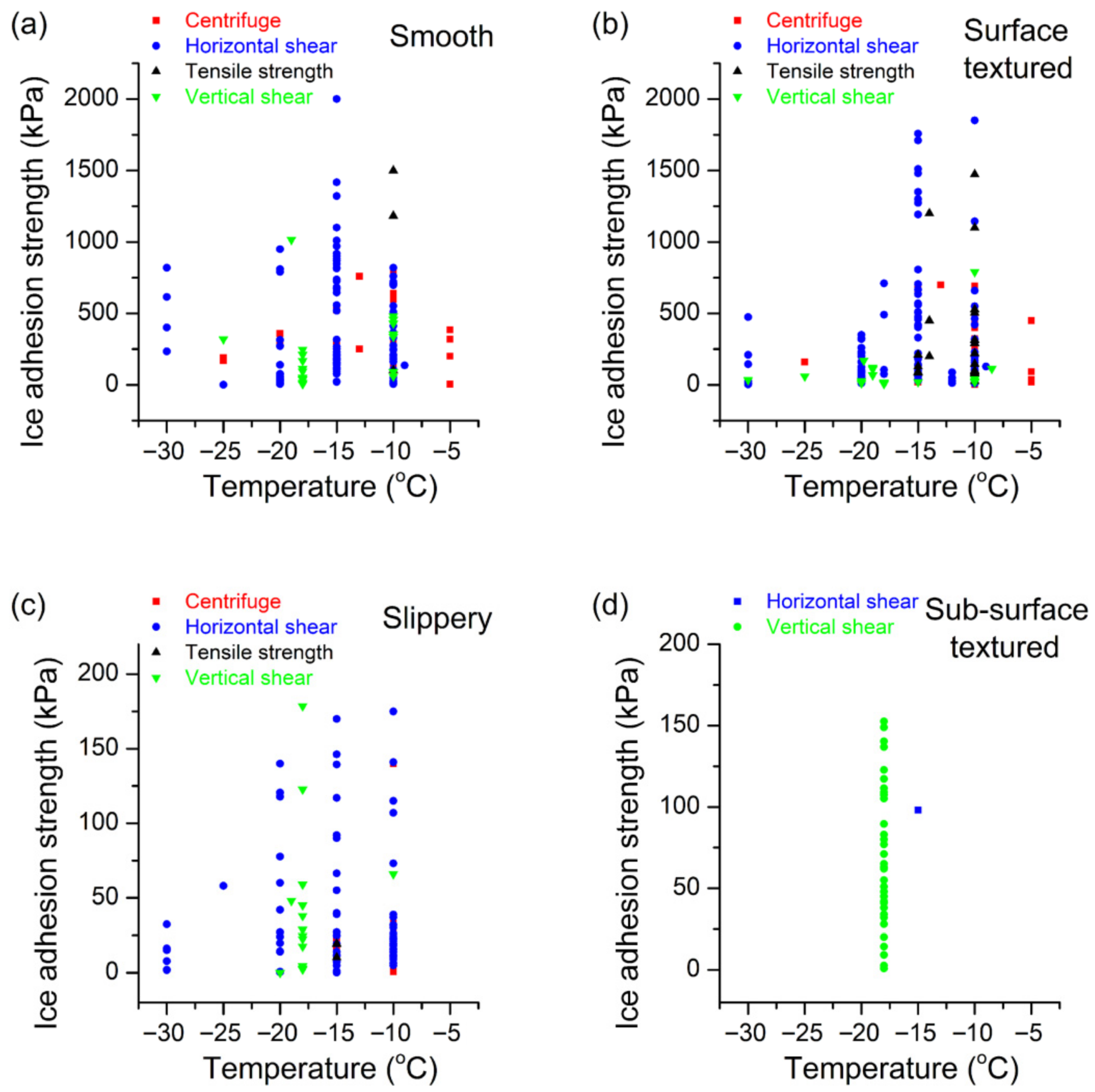
Figure 3 compiles the literature data for smooth, textured, slippery, and sub-surface-textured surfaces, grouped by test method and temperature, following the classification in [14]. The wide spread in reported τ ice at a given temperature and surface class should not be interpreted solely as random experimental error: it also reflects strong protocol dependence (ice type and formation route, mold confinement, dwell time/thermal history, loading mode/rate/alignment, and adhesive vs. cohesive/mixed failure). This limitation is consistent with recent multi-laboratory comparisons showing that different test configurations can yield ice-adhesion values that differ by orders of magnitude even when identical surfaces are tested under harmonized parameters, highlighting the need for careful reporting and benchmarking [23]. With these caveats, the compiled ranges still support robust trends: smooth hydrophobic surfaces typically yield moderate reductions relative to bare metals, superhydrophobic textures can reduce adhesion further when Cassie stability is maintained, and slippery or low-interfacial-toughness designs can reach substantially lower apparent adhesion by suppressing pinning and promoting interfacial crack initiation/propagation [10,14,24,25].
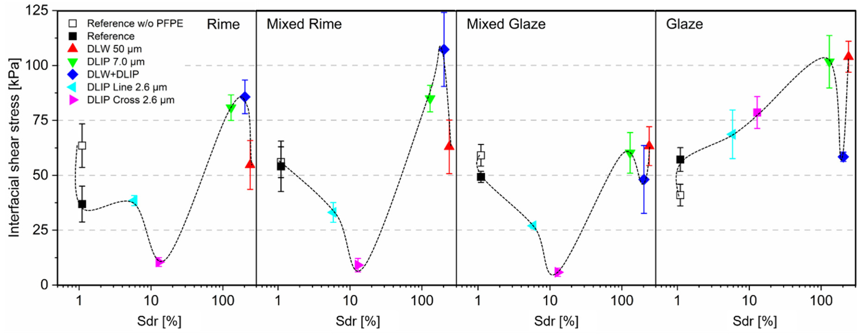
The relation between roughness and interfacial shear is non-monotonic: increasing developed area S d r can first reduce and then increase τ ice depending on whether the texture remains in a Cassie-like state or becomes impaled and strongly pinned. Figure 4 illustrates this trend for multi-scale laser-treated aluminum samples under rime, mixed, and glaze icing conditions from Milles et al. [26]. At low S d r , added roughness decreases adhesion by reducing real contact and enhancing droplet mobility; at higher S d r , however, capillary impalement and mechanical interlocking dominate, and τ ice increases again. These results emphasize the need to design not only the magnitude but also the morphology and distribution of roughness features.

3.4. Fractal Roughness and Contact-Line Pinning

Fractal-like rough surfaces present pinning sites across a broad range of scales for advancing and receding contact lines or advancing ice fronts, increasing hysteresis and interfacial toughness. Nosonovsky and Hejazi showed that superhydrophobicity does not guarantee icephobicity: surfaces that bead water extremely well can still anchor solid ice once freezing proceeds into the texture, particularly when frost bridges form between asperities [16]. In their analysis, fractal descriptors and multi-scale roughness statistics correlated better with ice adhesion than a single roughness parameter such as R a , reflecting the importance of pinning sites across scales.
Conversely, deliberate patterning (e.g., aligned microgrooves or periodic ridges) can guide crack paths and reduce effective interfacial toughness by promoting controlled debonding rather than random fracture [14]. Modeling and recent experiments suggest that certain patterns encourage crack initiation or interfacial cavitation at lower driving forces, thereby lowering adhesion [17,25]. In practice, controlled hierarchical structures are preferred over uncontrolled, random fractality to reduce unpredictable pinning and facilitate repeatable ice-shedding behavior.

3.5. Mechanistic Links Between Roughness, Wettability, and Ice Adhesion

The Young–Dupré relation links the thermodynamic work of adhesion W a between a liquid and a solid to the liquid–vapor surface tension γ L V and the equilibrium contact angle θ :
W a = γ L V 1 + cos θ .
In practice, using the receding angle θ rec gives a better correlation with measured ice adhesion because it incorporates contact-line pinning and hysteresis [14,19,20]. Low θ rec (strong pinning) typically corresponds to higher τ ice , whereas high θ rec and low hysteresis correlate with lower τ ice across a range of textures and chemistries [17,19,20].
Roughness that sustains a Cassie state reduces W a and often τ ice by minimizing true contact area, but complex asperities and deep pores can increase pinning and negate these benefits once liquid or ice penetrates the texture. Mechanical interlocking within deep grooves or undercut pores further increases adhesion. Minimizing true contact area, avoiding interlocks, and limiting pinning via composite interfaces (air pockets or infused lubricants) are therefore key strategies. Representative wetting and ice-adhesion performance for common surface types are summarized in Table 1; as discussed in Section 4 and Section 6, achieving ultra-low τ ice (a few kPa or less) often requires moving beyond purely hydrophobic textures toward compliant or liquid-mediated interfaces such as soft elastomeric coatings and SLIPS [10,12,24,25].

4. Ice-Adhesion Measurement Techniques

Accurately quantifying the adhesion strength of ice to a substrate is non-trivial. Common adhesion tests differ in loading mode, sample geometry, and environmental history, and these differences can lead to widely scattered values even for nominally similar coatings [8,14,17]. Most techniques freeze a defined ice volume or layer on a test substrate and then apply a controlled load until detachment, reporting a nominal shear strength
τ ice = F A ,
where F is the peak load at failure and A is the apparent contact area. Variations in loading mode (shear vs. tension), ice morphology (rime vs. glaze), strain rate, and the presence of residual stresses or defects can all influence the measured τ ice [8,11,17]. It is worth noting that significant uncertainty remains, as no predictive model yet exists for ice adhesion, and discrepancies persist between molecular-dynamics simulations and laboratory measurements [31].
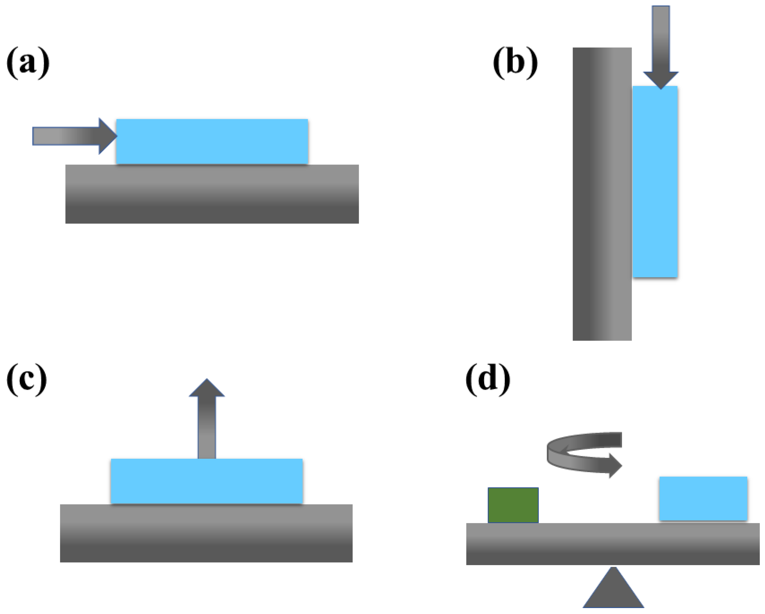
Figure 5 schematizes four widely used approaches: horizontal shear (push), vertical shear, tensile pull-off, and centrifugal methods. This section outlines their main features, typical assumptions, and common artifacts, emphasizing how these factors affect interpretation and comparison across studies.

4.1. Shear (Push-Off) Tests

In push-off tests, a cylindrical or prismatic stub of ice is grown or cast on the test surface (often inside a mold) and then loaded laterally until it shears off. The peak force divided by the nominal contact area gives τ ice . Several studies use ice cylinders of 20–30 mm diameter with the load applied close to the interface to reduce bending [8,11,19]. Careful control of icing conditions (water quality, temperature history, and cooling rate) is required to obtain reproducible glaze ice at the interface; otherwise, cohesive failure within a porous rime layer may dominate.
Artifacts include non-uniform stress distributions (especially for tall or slender cylinders that can bend or topple), friction against the mold walls, and mixed-mode loading if the push head is misaligned. To ensure that the ice–substrate interface is the weakest link, many protocols specify a fixed test temperature (e.g., 10   ° C ), a dwell time after freezing, and a thickness range for the ice layer [8,17]. When these conditions are not standardized, direct comparison of τ ice values between different laboratories becomes difficult.

4.2. Tensile (Pull-Off) Tests

Tensile or pull-off tests apply a normal load to the ice via a stud or dolly bonded to the ice surface. The assembly is pulled perpendicular to the substrate until failure, ideally probing mode I separation. Such tests are often adapted from paint-adhesion standards (e.g., ASTM D4541 [32]), which prescribe dolly geometry and loading rate. Alignment is critical: any tilt or misalignment introduces a shear component that can substantially reduce the apparent tensile strength [8,14].
Although pure tensile loading is less representative of many service conditions (where shear or mixed-mode loading dominates), pull-off tests are valuable for identifying failure modes (adhesive vs. cohesive) and for quantifying the intrinsic normal strength of the interface. They are also convenient when space constraints make lateral loading difficult. However, the need for an adhesive between ice and dolly adds another interface that can sometimes fail first, complicating data interpretation [17].

4.3. Centrifugal Tests

Centrifugal adhesion tests mount one or more coated samples with ice layers on a rotating arm or drum and progressively increase the rotational speed until the ice detaches. The critical speed or acceleration at detachment is used to back-calculate an equivalent shear stress at the interface. This approach is attractive for rapid screening because many samples can be tested simultaneously under identical thermal conditions [8,11].
Artifacts arise from aerodynamic drag on the ice, non-uniform ice thickness or density along the sample, and uncertainties in the effective detachment area. Furthermore, centrifugal loading is inherently mixed mode (normal and shear components) and spatially varying. Consequently, care must be taken when comparing centrifugal τ ice values with those from quasi-static push- or pull-off tests [14,17]. Nevertheless, centrifugal methods are widely used in industrial screening campaigns due to their throughput and relative simplicity.

4.4. Other Methods and Normalization Strategies

Additional methods include impact tests (pendulum or drop-weight), torsional loading of ice cylinders, and three-point bending of ice beams bonded to surfaces. These geometries probe different combinations of mode I and mode II fracture and are sometimes used to extract an apparent interfacial toughness rather than just a strength [14]. Because results are strongly dependent on loading mode, rate, and ice morphology, it is increasingly common to report an adhesion reduction factor (ARF), defined as
ARF = τ ice , ref τ ice , surface ,
where τ ice , ref is the adhesion on a reference substrate such as polished aluminum under identical test conditions [8,17]. ARF helps to compare coatings tested in different rigs or laboratories, provided the reference surface and protocol are clearly documented.
Across all methods, standardized procedures and detailed reporting of experimental conditions (ice type, temperature, humidity, cooling rate, dwell time, surface roughness, sample geometry, and loading rate) are essential to enable meaningful comparison and meta-analysis of icephobic performance [8,14,17]. Ongoing efforts toward consensus standards for ice-adhesion testing should improve reproducibility and help bridge the gap between laboratory measurements and field-relevant performance.

4.5. Toward Comparable Ice-Adhesion Data: Minimum Reporting and Emerging Standards

To improve comparability across push-off, pull-off, and centrifugal methods, the following minimum reporting set is recommended [8,17]: (i) ice type and formation route (static vs. impact; rime vs. glaze where applicable); (ii) water quality, cooling rate, dwell time, and full temperature history at the interface; (iii) ice geometry (area and thickness) and how the nominal contact area A is defined; (iv) loading mode, loading rate, fixture alignment, and whether mixed-mode components are present; (v) number of replicates and statistical dispersion; and (vi) observed failure mode (adhesive vs. cohesive vs. mixed) and residual ice coverage. For high-throughput centrifugal testing of rotor-blade coating systems, ISO/TS 19392-6:2023 provides a structured framework defining basic ice types and test parameters to improve reproducibility [33]. Multi-laboratory evidence nevertheless shows that even with harmonization, different test configurations can yield substantially different absolute values; therefore, reporting ARF relative to a benchmark tested in the same setup and corroborating performance using more than one test geometry is strongly encouraged [23]. Finally, for early-stage material ranking when access to full icing facilities is limited, simple screening approaches have been proposed (e.g., double lap shear-based ranking) to provide consistent relative ordering using minimal infrastructure [34].

5. Fabrication Methods for Icephobic Surfaces

Creating an icephobic surface typically involves sculpting surface texture (top-down), depositing or assembling functional coatings (bottom-up), or combining both approaches in a hierarchical manner. In most practical designs, top-down methods define the geometry and characteristic length scales that control wetting and mechanical interlocking, while bottom-up methods tune surface chemistry, mechanical compliance, and sometimes sub-surface architecture [1,12,14]. The choice of fabrication route is dictated by the target substrate (metal, polymer, composite), component size and shape, allowable surface roughness (particularly critical in aerodynamics), and cost or throughput constraints. This section surveys widely used fabrication strategies, emphasizing how each method links to the icephobic mechanisms discussed in Section 2 and Section 3 and to durability issues elaborated in Section 8.
Beyond listing fabrication techniques, it is useful to compare methods by the mechanism lever they enable and the dominant durability limits they introduce. Top-down texturing (e.g., laser, etching, anodizing) primarily tunes Cassie stability, impalement resistance, and geometry-driven interlocking/crack initiation; bottom-up coatings (e.g., sol–gel, spray nanocomposites, thermal spray + sealers) primarily tune chemistry, compliance, and damage tolerance; and SLIPS require both a scaffold and an infused lubricant so their long-term behavior is frequently controlled by lubricant retention under shear and environmental exposure [14,17,24]. Table 2 summarizes these trade-offs for common fabrication families.

5.1. Top-Down Techniques (Micro/Nano-Texturing)

Top-down methods directly pattern the substrate to create micro- or nano-scale roughness that supports Cassie–Baxter wetting, promotes droplet mobility, and, in some cases, facilitates interfacial crack initiation during de-icing. When combined with a low-surface-energy overlayer, such textures can reduce the real ice–substrate contact area and suppress mechanical interlocking [14,16].
Laser ablation and texturing: Laser processing can generate microgrooves, microcones, and nano-ripples (laser-induced periodic surface structures, LIPSS) on metals, polymers, and ceramics by tuning wavelength, pulse duration, fluence, and scan speed. Picosecond and femtosecond lasers are particularly attractive because they enable ablative texturing with minimal heat-affected zones and can simultaneously produce multi-scale (micro + nano) roughness in a single step [1]. After hydrophobization with fluorosilanes or fluoropolymer overcoats, such surfaces often show static water contact angles exceeding 160 ° and low sliding angles, which translates into reduced ice adhesion and delayed frost formation [14]. For example, Milles et al. created multi-scale laser-textured aluminum surfaces for aeronautic applications and reported ice-adhesion strengths in the range of a few tens of kPa, along with good stability over repeated icing/de-icing cycles [26]. Similar approaches have been explored on titanium and stainless steel, highlighting the versatility of laser texturing for high-value metallic components. Advantages include maskless processing, digital control of patterns, and applicability to curved or complex geometries, whereas limitations are primarily related to equipment cost and throughput for very large areas.
Lithography and etching: Photolithography or nanoimprint lithography combined with reactive-ion etching, wet chemical etching, or deep-etch processes can produce highly controlled arrays of micro- and nano-features (e.g., posts, cones, overhangs) on silicon, glass, or metal substrates. These methods originated in microelectronics and MEMS fabrication and allow precise tuning of feature size, spacing, and re-entrant geometry—parameters known to govern Cassie-state stability and impact-induced impalement [1,12]. When subsequently hydrophobized, such patterned substrates have been used as model systems to systematically probe the influence of roughness on condensation frosting, droplet impact, and ice adhesion [21,22]. However, their use in large-scale infrastructure is currently limited by process cost, planar geometry constraints, and the need for cleanroom infrastructure.
Abrasive/mechanical roughening: Sandblasting, shot peening, grit blasting, and micromilling introduce stochastic roughness over areas ranging from cm2 to m2. These techniques are widely available in industry and can be applied to large, curved components such as turbine blades or pylons. When followed by hydrophobization (e.g., spraying or dipping in fluorinated or silicone-based coatings), they could reduce ice adhesion relative to smooth substrates, particularly when the resulting morphology supports a partial Cassie state [11,19].
Anodizing and porous oxides: Anodized aluminum oxide (AAO) and related porous-oxide layers (e.g., on titanium) provide ordered or semi-ordered nanoporous networks with pore diameters typically spanning 20–200 nm and thicknesses up to tens of micrometers. These porous layers can be hydrophobized to obtain superhydrophobicity, or, alternatively, infused with a lubricating liquid to create SLIPS interfaces (see Section 6) [14,24]. The anodic layer is strongly bonded to the underlying substrate, which enhances mechanical robustness compared with loosely attached nanoparticle paints. At the same time, brittleness and susceptibility to cracking under bending or impact, as well as the need for additional surface-energy modification, are important considerations for highly loaded structural components.
Architected and sub-surface-textured substrates: Beyond simple surface roughening, there is growing interest in sub-surface texturing and architected materials, in which cavities, channels, or compliant interlayers are incorporated beneath the outer surface to manipulate stress distributions during ice detachment [14]. For instance, aligned grooves or sub-surface voids can act as crack initiators and guide interfacial fractures, effectively reducing the apparent toughness of the ice–substrate interface without compromising the macro-scale integrity of the component. Such concepts are still largely at the laboratory stage but illustrate how top-down patterning can be used not only to control wetting but also to engineer fracture mechanics.

5.2. Bottom-Up Techniques (Coatings and Deposition)

Bottom-up approaches build icephobic functionality by depositing thin films, multilayers, or composite coatings onto a substrate. These methods are especially powerful for tailoring surface chemistry (e.g., low surface energy, hydrogen-bonding character), mechanical compliance, and, in some cases, the presence of mobile phases (lubricants, liquid-like polymer segments). In practice, many commercial or field-tested icephobic treatments are based on bottom-up coatings applied to pre-existing components [9,17,19].
CVD and molecular-scale coatings: Vapor-phase deposition of organosilanes, fluorocarbons, or organosilazanes via chemical vapor deposition (CVD) or initiated CVD (iCVD) yields conformal, nanometer-scale films with low surface energy and good chemical uniformity. Such monolayers or ultra-thin polymer coatings are particularly attractive for applications where macroscopic roughness and optical clarity must be preserved (e.g., radomes, sensor windows), as they add minimal thickness and do not significantly alter surface topography. Their icephobic performance is typically modest (adhesion reduction factors of ∼2–3 relative to bare aluminum) because they do not drastically change roughness or compliance [1,19]. Nonetheless, they can serve as primer layers that improve the adhesion and durability of thicker icephobic topcoats.
Sol–gel and dip coating: Sol–gel processes allow the formation of silica or hybrid organic–inorganic networks containing embedded hydrophobic moieties and nano- or micro-particles. By adjusting precursor chemistry, condensation conditions, and withdrawal speeds, one can tune film thickness, porosity, and roughness, thereby transitioning from smooth hydrophobic to superhydrophobic states [12,19]. Dip coating or spin coating of sol–gel formulations onto metals, polymers, or glass has been widely explored for icephobic and anti-fog applications. Incorporating elastomeric binders or flexible organic segments into the sol–gel matrix can mitigate cracking and improve resistance to thermal cycling. However, purely inorganic or brittle networks are susceptible to chipping and microcracking under impact or bending, which may rapidly degrade icephobic performance [17].
Spray coatings (nanocomposites): The spray deposition of polymer–particle suspensions is one of the most scalable routes to superhydrophobic and icephobic surfaces. Typical formulations combine a binder (e.g., silicone, polyurethane, acrylic) with low-surface-energy particles (e.g., fluorinated silica, PTFE, polypropylene, or polyethylene powders) dispersed in a volatile solvent [11,19]. Upon evaporation, a micro/nanostructured coating forms, often displaying water contact angles above 150 ° and contact-angle hysteresis below 10 ° , while reducing τ ice by factors of 2–3 relative to uncoated aluminum [19]. The binder composition is critical: harder binders enhance abrasion resistance but may increase contact-line pinning, whereas softer binders improve compliance and ice release but can be more vulnerable to erosion. Recent aeronautical studies have demonstrated superhydrophobic spray coatings that maintain low ice adhesion over multiple icing cycles and rain-erosion tests, although some loss of performance with time is unavoidable [17,28]. Spray processes are compatible with large blades, towers, and nacelles, making them attractive for wind and power applications.
Thermal-spray coatings: Thermal spraying (e.g., atmospheric plasma spraying, suspension plasma spraying, or HVOF) of inorganic powders such as TiO2 or Al-based quasicrystalline alloys produces thick, relatively rough ceramic or metallic–ceramic coatings whose surface topography and porosity can be tuned by process parameters and post-treatments. Plasma-sprayed TiO2 coatings have been engineered to exhibit hydrophobic or superhydrophobic wetting and reduced ice adhesion by controlling micro/nano-scale hierarchical morphology [35,36]. Quasicrystalline coatings deposited by HVOF and related processes similarly show reduced ice accretion and durable low interfacial toughness with ice [37,38]. On engineering structures relevant to power transmission and aeronautics, such thermally sprayed coatings offer mechanically robust, scalable icephobic surfaces and can also act as porous scaffolds for lubricant-infused slippery surfaces (SLIPS) or other overcoatings [39].
Electro/electroless deposition and metal–polymer composites: Electroplating or electroless deposition processes can embed low-surface-energy particles (e.g., PTFE) or soft polymer phases within a metallic matrix such as nickel, copper, or zinc. The resulting metal–polymer composite coatings are mechanically robust, electrically conductive, and often exhibit micro- or nano-scale roughness that can be further tuned via processing parameters. These characteristics make them relevant for power infrastructure (where electrical properties matter) and for structural components requiring wear resistance [14,17]. Post-treatment with hydrophobizing agents can further lower surface energy and promote Cassie-like states.
Bioinspired polymers, gels, and tethered liquid-like layers: Inspired by natural systems such as pitcher plants and cartilage, several groups have developed soft polymeric and gel-based coatings that achieve low ice adhesion via interfacial compliance and/or the presence of mobile, liquid-like surface segments. Examples include low-crosslink-density silicones, polyurethanes, and hydrogels that possess high compliance or lubricity [10]. Tethered liquid-like polymer layers—in which short, mobile chains are covalently anchored to a solid backbone—have also been proposed as robust, self-healing icephobic interfaces that combine low interfacial toughness with chemical stability [25]. These systems often achieve shear ice-adhesion strengths below 10–20 kPa and can exhibit size-independent de-bonding behavior (Section 6), but their long-term resistance to abrasion, contamination, and UV exposure remains an active research topic [17].
Lubricant-infused porous surfaces (SLIPS): Although discussed in more detail in Section 6, it is worth noting here that SLIPS are fundamentally a two-step bottom-up fabrication: first, a porous or rough scaffold (produced by anodizing, sol–gel, etching, or spraying) is created; second, an immiscible lubricant is infused into this scaffold [1,24]. The infused liquid forms a smooth, mobile interface that dramatically reduces contact-angle hysteresis and τ ice . Careful matching of lubricant viscosity, surface tension, and chemical affinity with the solid matrix is essential for long-term lubricant retention under shear and thermal cycling.

5.3. Durability and Scale-Up

Regardless of fabrication method, a critical challenge is ensuring that the coating or texture can endure the mechanical, thermal, and chemical conditions of its intended use over many icing/de-icing cycles. As emphasized in recent durability reviews [17], the micro- and nano-scale features that impart strong icephobicity are often the first to be damaged by abrasion, erosion, or contamination.
Mechanical wear from wind-blown sand, rain, hail, or debris can erode micro/nano-textures or wear away coatings. Many superhydrophobic surfaces lose their properties after relatively mild abrasion, shifting from a Cassie-like to a Wenzel-like state and thereby increasing τ ice [11,17]. Strategies to improve wear resistance include using harder materials (ceramic or metallic textures) beneath a thin hydrophobic layer, embedding wear-resistant nanoparticles within elastic binders (nanocomposites), or designing coatings with self-healing capabilities so that scratches can be refilled with hydrophobic material [10,17]. A durable icephobic surface developed by Golovin et al. used a bulk elastomeric coating with uniform low crosslink density through the thickness, which maintained low ice adhesion even after significant abrasion and cutting damage [10].
Environmental degradation is another important factor. Organic coatings (polymers, monolayers) can degrade under UV light, ozone, humidity, and temperature cycling, leading to embrittlement or loss of hydrophobic functional groups. Fluoropolymers and silicones are generally more UV-stable than many other polymers, but prolonged exposure still reduces performance [8,17]. Consequently, accelerated weathering tests (UV exposure, salt spray, freeze–thaw cycling) are increasingly incorporated into icephobic coating evaluations to assess long-term stability [9]. Coatings may require UV stabilizers, antioxidant additives, or periodic re-application in harsh outdoor environments.
The adhesion of the coating to the substrate is equally critical. Many nanoparticle-based superhydrophobic paints exhibit poor adhesion and can delaminate under thermal cycling or when ice detaches, effectively “peeling” the coating off with the ice [9,11]. Surface priming (e.g., grit blasting, chemical etching) and the use of coupling agents (e.g., silanes) or high-adhesion binders (epoxy, polyurethane) can greatly improve coating–substrate bonding. Some recent systems use a layered architecture: a strongly adherent, mechanically robust primer that bonds to the substrate, topped by a thinner, more delicate icephobic layer that can be renewed without removing the primer [17].
Finally, scale-up considerations strongly influence which fabrication methods are viable for specific applications. Techniques such as spraying, roll-to-roll coating, and tape-like films are being developed to apply icephobic treatments to large structural surfaces (e.g., wind-turbine blades, power cables, aircraft wings) in a cost-effective manner [4,27,28]. For example, one concept is an icephobic “tape” for leading edges that can be applied in the factory or in the field and replaced when worn, shifting complex fabrication steps to a controlled industrial environment. In practice, current commercial offerings are often sacrificial coatings or paints that can be re-applied as part of routine maintenance. Even so, by significantly reducing ice accretion between maintenance intervals, such treatments can yield substantial operational and safety benefits. Developing truly long-lived icephobic surfaces—capable of surviving years of service without reapplication—remains a central goal that drives ongoing work in materials selection, coating architecture, and process optimization.

6. Low-Interfacial-Toughness and Slippery Approaches

Reducing τ ice is necessary but not always sufficient to ensure easy removal of large ice accretions. On many conventional superhydrophobic or smooth hydrophobic surfaces, adhesion is essentially strength-limited: the maximum shear or tensile stress the interface can sustain scales with area, so the total force required to shed a large patch of ice grows approximately as F = τ ice A [14]. In contrast, for toughness-limited interfaces, de-bonding is governed by interfacial crack propagation rather than local strength, and the force required to remove large ice patches can become nearly size-independent once a crack is nucleated [24,25]. Low-interfacial-toughness (LIT) materials and architectures are therefore an important complement to low- τ ice designs, as they minimize the energy release rate required to propagate an interfacial crack and can enable large-scale shedding under modest loads [12,25].

6.1. Toughness-Limited vs. Strength-Limited Behavior

Traditional superhydrophobic surfaces typically remain strength-limited: local failure may initiate at relatively low interfacial stress, but large patches still require large total forces because crack propagation is impeded by strong pinning and mechanical interlocking within the texture [14,16]. In such cases, reducing τ ice through lower surface energy or reduced real contact area is beneficial, but the detachment force still grows with ice-covered area.
LIT designs seek to change the failure mode. By tailoring the compliance of the substrate, introducing weak or lubricated interfacial layers, or engineering stress concentrators that promote crack initiation, LIT surfaces encourage controlled interfacial fracture at low driving force [25]. Golovin et al. showed that for a broad class of soft and slippery coatings, ice detachment could be described in terms of an “ice-reduction potential” l * that captures the balance between interfacial toughness and the characteristic stress distribution; coatings with low interfacial toughness exhibited a saturation in the force required to shed larger ice patches, indicative of a toughness-limited regime [25]. This distinction is crucial for real components (e.g., wings, blades, power lines) where ice-covered areas can be large.

6.2. Soft Polymeric Coatings and Gels

Soft elastomers (e.g., PDMS with low crosslink density) and related polymeric gels are prototypical LIT materials. Their low elastic modulus reduces interfacial shear transfer and promotes interfacial cavitation or decohesion at relatively low loads, yielding τ ice below 10 kPa in shear tests and even lower forces in peel configurations [10,25]. In addition, their compliance allows local stress concentrations to relax, favoring interfacial crack propagation rather than cohesive fracture of the ice.
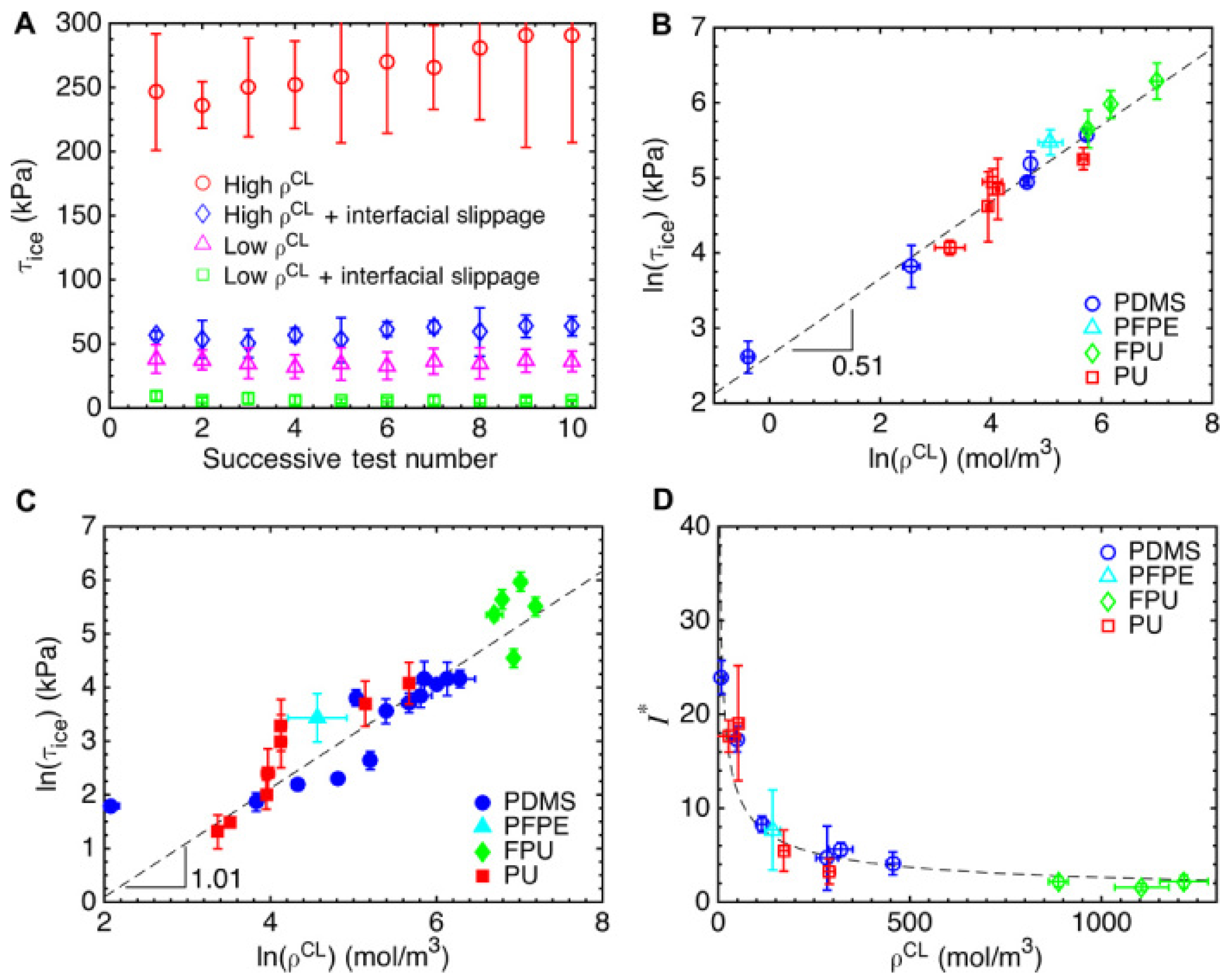
Systematic studies of crosslink density have revealed clear trends. Golovin et al. demonstrated that decreasing the crosslink density ρ CL of PDMS coatings (and related elastomers) leads to a pronounced reduction in τ ice , especially when combined with interfacial slippage at the ice–coating interface [10]. Figure 6 quantifies how ρ CL and interfacial slippage modulate adhesion and the ice-reducing potential l * : in the absence of slippage, τ ice scales strongly with ρ CL , whereas in the presence of slippage, τ ice becomes much less sensitive to modulus and can reach very low values across a broad range of formulations.
Trade-offs include wear resistance, contamination, and environmental stability. Very soft polymers are more prone to erosion, scratching, and uptake of oils or particulates, all of which can increase pinning and degrade performance over time [17]. Formulation strategies include using block copolymers or nanocomposites that combine a compliant matrix with reinforcing domains, or incorporating self-healing chemistries that can repair surface damage while preserving low interfacial toughness [10,17]. Nonetheless, soft coatings have demonstrated some of the lowest repeatable τ ice values reported, and they serve as a key benchmark for LIT behavior.

6.3. Slippery Liquid-Infused Porous Surfaces (SLIPS)

Slippery liquid-infused porous surfaces (SLIPS) use a textured or porous scaffold infused with an immiscible lubricant to present a smooth liquid interface to water and ice. The infused liquid fills the roughness, displacing air and creating a defect-free, mobile interface that exhibits extremely low contact-angle hysteresis and very low τ ice (often a few kPa or less) [1,24]. Because the water or ice phase interacts primarily with the lubricant, pinning at solid asperities is suppressed and interfacial toughness is greatly reduced.
Designing effective SLIPS requires careful matching of scaffold geometry, lubricant properties, and working fluid. The solid matrix must be preferentially wetted by the lubricant to ensure capillary retention; pore sizes and surface chemistry are selected so that the lubricant remains stable under shear, gravity, and thermal cycling [24]. Lubricant retention is the primary challenge; depletion via evaporation, shear-driven drainage, or cloaking by the working fluid can gradually degrade performance. Strategies to mitigate this include using viscous or functionalized lubricants, employing re-entrant or overhanging pore geometries that enhance capillary anchoring, and combining SLIPS concepts with soft elastomeric substrates to further reduce interfacial toughness [1,12,17].
Beyond ice, SLIPS also resist other fouling modes (e.g., scale, organisms, particulates), making them attractive for multi-functional anti-fouling and anti-icing applications. However, questions remain regarding long-term durability, environmental impact of lubricants, and performance under severe icing fluxes, which are active topics of research and are critically assessed in recent reviews [1,12,17]. Reported ultra-low shear adhesion values (often below ∼20 kPa) for SLIPS and soft elastomers are typically obtained under specific laboratory protocols with defined ice formation routes, geometries, and loading configurations [10,24,25]. Reproducibility across laboratories is limited by differences in ice type/formation and test geometry, as demonstrated by multi-lab comparisons showing large method-dependent variations even for identical surfaces [23]. Long-term stability is frequently governed by distinct degradation pathways: for SLIPS, lubricant depletion increases hysteresis/pinning and raises τ ice ; for soft coatings, wear, contamination, and coating–substrate adhesion can dominate performance decay [17]. Recent multi-scale validation of a commercial silicone–epoxy coating further shows that coupon-scale low adhesion after cycling can shift toward cohesive or mixed detachment for realistic accretions at larger scale, leaving residual ice despite favorable laboratory values [40].

7. Application Case Studies

Icephobic materials are typically introduced through coupon-scale metrics such as ice-adhesion strength τ ice and icing delay time. However, performance in service is often governed by factors that are weakly represented in laboratory screening tests, including mixed ice morphologies (rime/glaze/wet snow), aerodynamic shear, particle erosion, UV/weathering, contamination, and thermal/mechanical cycling. Consequently, coatings that appear promising in the laboratory may underperform or fail by different mechanisms when evaluated under more realistic conditions [17,40]. This section highlights five representative application areas—aircraft, wind turbines, power infrastructure, sensors, and civil engineering–where passive or hybrid icephobic strategies are being explored.

7.1. Aircraft (Aviation)

Transport and commuter aircraft currently rely primarily on active systems (hot bleed air, electro-thermal heaters, and pneumatic boots) to meet strict certification requirements [2,3]. Passive coatings cannot replace these systems at present, but they can complement them by delaying ice accretion, reducing adhesion, and thereby lowering the duty cycle of de-icing systems and the amount of chemical de-icer required [1,14].
Coatings for aeronautical applications must withstand UV radiation, cosmic radiation, aerodynamic loads, rain and sand erosion, as well as de-icing chemicals, all while preserving the smoothness of aerodynamic surfaces. Recent icing-tunnel tests on superhydrophobic and icephobic coatings applied to aluminum or composite substrates showed slower ice accretion, reduced residual ice thickness, and easier shedding compared with uncoated controls, particularly under glaze-icing conditions relevant to in-flight icing [28]. However, performance often degrades after rain-erosion and sand-erosion exposure, highlighting durability limits [17,28].
Hybrid solutions pairing low-power electro-thermal heating with passive coatings are especially promising where fully active systems are impractical or too energy-intensive, such as on small unmanned aerial vehicles (UAVs) or rotorcraft components [4,12]. In such concepts, the coating reduces the adhesion strength and required heat flux, while the heater provides robustness under severe icing events.

7.2. Wind Turbines

Icing on wind-turbine blades reduces power output, increases aerodynamic noise, and can generate dangerous ice throw. Field measurements and simulations indicate substantial energy losses during icing seasons at cold-climate sites [4,5]. Passive icephobic coatings on leading edges and suction sides can facilitate centrifugal shedding and reduce adhesion of wet snow or freezing drizzle, thereby shortening downtime and improving capacity factors [1,12].
Field trials and full-scale blade tests have shown that superhydrophobic or icephobic coatings can reduce ice accretion volume and increase shedding frequency, but durability of leading-edge coatings under rain erosion and particulates remains a major hurdle [4,17]. Combining coatings with modest blade heating (e.g., embedded resistive elements or warm air) is a promising compromise: coatings lower the energy required to clear ice, while heating ensures recovery during extreme events [4,5]. Coatings must also avoid aerodynamic penalties during ice-free operation, which constrains allowable roughness and thickness.

7.3. Power Lines and Other Infrastructure

Power transmission lines, insulators, and support structures experience significant icing loads in cold climates. Heavy accretions can cause mechanical overload, galloping, flashovers, and outages [6,7]. Icephobic coatings applied to conductors, insulators, and towers can reduce ice loads and facilitate natural shedding by wind-induced vibration or gravity.
For high-voltage equipment, electrical compatibility, ampacity, corona effects, and pollution flashover performance constrain allowable materials and coating thicknesses. Hydrophobic room-temperature-vulcanizing (RTV) silicone coatings on insulators have been shown to reduce wetting, delay ice accretion, and decrease the likelihood of icing-induced flashovers [6,27]. For towers, masts, and similar structures, robust polymer or composite coatings can decrease maintenance needs and mitigate hazards from falling ice, although re-application logistics and service life remain key considerations [9,17,27].
Emerging LIT and SLIPS-inspired coatings are being evaluated on power hardware in cold chambers and field test lines. Early results suggest that even partial reductions in τ ice can significantly decrease the frequency and severity of icing events when combined with appropriate line design and maintenance practices [6,9].

7.4. Sensors and Devices

Delicate sensors—including airport weather sensors, anemometers, LiDAR units on autonomous vehicles, camera lenses, and drone-mounted cameras—are also prone to icing and frosting. Even a thin ice layer can render such devices inoperative or degrade measurement accuracy. Transparent or translucent icephobic coatings that maintain optical clarity while reducing frost and ice accumulation are therefore of growing interest [1,12].
Examples include superhydrophobic or liquid-infused coatings on CCTV domes and optical windows, which can reduce frost formation and promote rapid clearing when subjected to mild heating or airflow. Sol–gel- or nanoparticle-based transparent coatings have been explored for automotive windshields and goggles, combining anti-fog (condensation control) with hydrophobic rain-repellent properties. For small unmanned aircraft, factory-applied hydrophobic or icephobic coatings on rotor blades and airframes have been reported to slow ice buildup and extend flight time in icing fog compared with uncoated vehicles, offering a passive means of risk reduction [12].
Similar strategies are being considered for sensors on power infrastructure (line monitoring sensors, ice detectors) and wind turbines (blade-mounted ice sensors), where icing of the sensor itself can compromise monitoring and control. In these applications, coatings must not interfere with sensor operation (optical, thermal, or electrical) and may be combined with low-power local heating or self-diagnostic algorithms.
Overall, across these case studies—aircraft, wind turbines, power lines, and sensors—icephobic surfaces show substantial potential to alleviate icing problems. In most realistic scenarios, they are most effective as part of a multi-faceted strategy: combining coatings with targeted heating, mechanical actuation, or design changes to manage ice accretion and shedding in an energy-efficient, robust manner [4,9,12,17].

7.5. Civil Engineering and the Built Environment

Civil-engineering applications (roads/asphalt pavements, bridge decks/cables, and building-envelope components) introduce constraints that differ from aerospace and wind energy: high abrasion and debris wear, chemical de-icers, UV/weathering, and safety-critical friction/skid-resistance requirements. Recent asphalt studies show that superhydrophobic coatings can reduce ice bonding and extend freezing time, but also report measurable changes in pavement friction metrics that must be managed for safe deployment; additionally, anti-icing benefits can degrade after limited freeze–thaw cycling [41]. These constraints motivate designs emphasizing abrasion-resistant binders, strong coating–substrate adhesion on porous/rough civil substrates, and maintenance-compatible renewal strategies rather than fragile high-aspect-ratio textures [17].

8. Challenges and Future Outlook

While significant progress has been made in understanding and improving passive icephobic surfaces, translation to long-lasting engineering solutions remains limited by durability, protocol dependence of reported metrics, and scale effects in accretion and detachment. Recent advances include low-interfacial-toughness concepts enabling easier large-area de-bonding [25], durability-focused materials development and failure-mode mapping [17], emerging test standardization efforts (e.g., centrifuge-based ISO/TS protocols for rotor-blade coating systems) [33], and recent multi-scale validation studies linking laboratory metrics to larger-scale and field-relevant performance while revealing failure-mode shifts at scale [40]. The following subsections summarize the most critical barriers and corresponding research directions needed for robust deployment.

8.1. Durability Under Real-World Conditions

A recurring challenge is the durability (or lack thereof) of many icephobic coatings. The very features that give a surface low ice adhesion—micro/nano-textures, soft polymers, lubricant films—are often vulnerable to wear and degradation. Superhydrophobic coatings, for instance, can lose their water repellency if the nano-textures are damaged or contaminated. Lubricant-infused surfaces may gradually lose lubricant through evaporation or washing. UV radiation can break down organic coatings over time. Therefore, enhancing durability is a top priority.
Possible approaches include:
  • Nanocomposites: Embedding wear-resistant nanoparticles in a resilient matrix to create coatings that are both robust and icephobic. For example, adding silica or alumina particles to a fluoropolymer can improve scratch resistance. Some studies have used inorganic fullerene-like nanoparticles (WS2) in epoxy to increase durability of icephobic paints.
  • Self-healing coatings: Incorporating microcapsules or dynamic polymer networks that can repair damage. For example, microcapsules that release a hydrophobic agent when ruptured could help a scratched superhydrophobic coating restore its low hysteresis ability. While self-healing concepts are often proposed for anti-corrosion, they could benefit anti-icing surfaces as well.
  • Surface renewal: In some cases, accepting that a coating is sacrificial and making it easy to renew is a practical solution. Examples include adhesive icephobic tapes that can be peeled off and replaced, or blades designed with quick-apply coating cartridges for maintenance crews.
In addition to reporting water contact angles, durability assessments should quantify retention of τ ice (or ARF) after abrasion/erosion and repeated icing/de-icing cycles, because relatively small increases in hysteresis/pinning can produce disproportionate increases in ice adhesion [17]. For example, a recent lab-to-blade evaluation of a silicone–epoxy icephobic coating reported ice adhesion below 20 kPa even after 50 icing/de-icing cycles alongside an abrasion metric, yet larger-scale spinning-blade and field conditions produced more cohesive/mixed failures with residual ice, highlighting that durability and scale must be evaluated jointly [40].
Another aspect of durability is maintaining performance under repeated icing/de-icing cycles. Some coatings show excellent low adhesion on the first cycle, but after many ice detachments, their performance degrades (possibly due to micro-cracks or loss of hydrophobic molecules). Therefore, cyclic testing is important. In the lab, accelerated aging tests such as abrasion, freezing/thawing, and salt spray are being applied to promising coatings to identify failure modes [17]. Going forward, a key objective will be to develop coatings that maintain low ice adhesion over many thousands of cycles while resisting mechanical and environmental damage.

8.2. Environmental and Safety Factors

New materials for icephobic surfaces must also be evaluated for environmental impact and safety. Some early superhydrophobic coatings used long-chain perfluorochemicals, which are now known to be environmentally persistent and potentially harmful (PFAS chemicals). Future coatings are therefore trending toward fluorine-free formulations, using alternatives such as silicones, hydrocarbon waxes, or zwitterionic polymers that are more eco-friendly while still providing low surface energy. From a deployment perspective, the most viable near-term pathways combine (i) scalable application (spray/roll/repairable topcoats), (ii) strong primer adhesion and erosion resistance, and (iii) reduced environmental burden (fluorine-reduced or fluorine-free binders where possible). Photothermal concepts are attractive for passive or hybrid mitigation, but recent reviews emphasize that commercialization is frequently constrained by mechanical durability, geometric adaptability, scalable production, and long-term chemical/thermal stability; these factors must therefore be treated as co-equal design objectives rather than secondary considerations [42].
Additionally, any debris or byproducts from coatings must not introduce other hazards. For instance, if a coating flakes off during ice shedding, those flakes could cause FOD (foreign object debris) issues in aviation or clog filters. Using strongly bonded coatings or soluble films that do not produce hard debris can mitigate such concerns.
Compatibility is another important consideration: an icephobic coating on a power line or aircraft must not adversely affect other properties such as electrical conductivity (for ground equipment), flame retardancy, or radar signature (for stealth surfaces). This means coatings often have to be multifunctional, or at least benign in other respects. Future work is likely to focus on eco-friendly, regulation-compliant formulations and on layered or gradient systems (e.g., a thin icephobic topcoat over a traditional protective coating) that satisfy multiple performance requirements simultaneously.

8.3. Standardization of Testing and Certification

Comparing results between different studies is difficult without standardized tests. One important step is the development of consensus standards for ice adhesion measurement (already underway with organizations like ASTM Committee G-21 on Antifreeze and Ice Control). With standard methods, coating developers can have clear targets (e.g., “must achieve ARF of 4 or greater in ASTM XYZ test after 100 abrasion cycles”). Certification processes for aviation or energy applications will likely require demonstrating performance after environmental conditioning (humidity, salt fog, UV exposure, etc.). Thus, test protocols that simulate realistic service conditions are essential.
Another important aspect is the development of reliable accelerated aging tests that correlate with field performance. For example, a rain erosion test rig (such as a whirling arm rain tester) might be used to simulate years of precipitation impact on a blade coating in a matter of hours. Similarly, alternating freezing rain and thaw cycles in a lab chamber could simulate seasonal stresses on a coating. Widespread deployment of prototypes on wind farms, test aircraft, power lines, and other infrastructure will provide valuable field data to validate these protocols. In the long term, harmonized standards and robust laboratory–field correlations will be crucial for certification and large-scale adoption.

8.4. Multi-Functionality and Adaptive Systems

Future anti-icing approaches are likely to integrate multiple functions in a single system. For example, an icephobic surface might also incorporate de-icing capability by being electrically conductive (to allow Joule heating) or photothermally active (to absorb sunlight and heat up). A recent trend is the development of photothermal icephobic coatings that are dark-colored or have embedded photothermal particles (such as graphene or gold nanorods); these coatings passively heat under sunlight to prevent ice buildup [12]. Another concept is using magnetically responsive coatings that can vibrate or flex slightly under an external magnetic field, aiding ice detachment.
There is also growing interest in sensing capability: a coating that can detect icing (via embedded optical fiber, microwave resonators, or impedance changes) and then trigger an active response or alert operators. For instance, a “smart skin” on a wing could detect a change in dielectric constant when ice forms and then activate a minor heating element only where needed, minimizing energy use.
While these ideas extend beyond purely passive surfaces, they underscore a future in which the boundary between passive and active anti-icing is blurred. Coatings may be mostly passive but incorporate small, intelligent components to improve reliability and efficiency, enabling hybrid systems that combine low ice adhesion with targeted, low-power interventions.

8.5. Machine Learning and Computational Design

Machine learning (ML) is increasingly being used to explore complex material design spaces. For icephobic surfaces, ML can help identify patterns in what makes a surface effective. For example, Ringdahl et al. [43] used an ML model to predict ice adhesion from nanoscale roughness parameters and found it could achieve good accuracy. Such models, once trained on sufficient data, could allow researchers to virtually screen thousands of texture–chemistry combinations and pinpoint promising candidates for experimental testing, thereby accelerating discovery.
ML could also help optimize trade-offs—for instance, balancing hydrophobicity with durability. If provided data on both ice adhesion and abrasion resistance for a series of coatings, an ML algorithm might find a “sweet spot” formulation that sacrifices a small amount of water repellency but gains substantially in toughness, yielding superior overall performance.
Another computational avenue is high-fidelity icing simulation. Combining CFD (computational fluid dynamics) with icing models [44] and surface physics can predict how ice will accrete and detach on different surfaces. While computational icing models already exist (e.g., for aircraft icing certification), they often assume idealized surface conditions. More refined models that incorporate varying contact angles, contact-angle hysteresis, and surface roughness could provide deeper insight into how different icephobic treatments affect ice accretion. Building shared databases and standardized workflows for such simulations, coupled with ML analysis, is a promising direction for guiding experiments and design. A key limitation for machine learning-guided optimization is the scarcity of standardized datasets that pair surface descriptors with comparable icing protocols and durability conditioning. Minimum data fields should include quantified texture descriptors (feature size distributions and areal parameters where possible), chemistry and modulus, full ice-adhesion metadata (ice type/formation route, temperature history, geometry, loading mode/rate, replicates/variance), observed failure mode, and post-conditioning results after abrasion/erosion and icing/de-icing cycling [17,23]. For self-healing icephobic coatings, critical evidence gaps include healing kinetics at subzero temperatures, repeatable damage/heal cycling, and demonstrated retention of low adhesion (ARF or τ ice ) after combined abrasion and repeated icing exposures.

9. Conclusions

Icephobic surface engineering has evolved into an interdisciplinary field aimed at tackling the long-standing problem of ice accretion. In this review, we surveyed the fundamental science of ice formation and adhesion, and how surface wettability and topography influence these processes. We examined how micro- and nanostructured superhydrophobic surfaces can delay ice onset and reduce ice–surface bonding, while also highlighting that extreme water repellency alone does not guarantee ultra-low ice adhesion. The development of low-interfacial-toughness materials and slippery coatings has opened new frontiers, enabling order-of-magnitude reductions in ice adhesion strength compared to traditional materials.
Notably, in controlled laboratory protocols, surfaces such as soft silicone coatings and lubricant-infused porous surfaces can achieve τ ice values in the tens of kPa or below, enabling shedding under relatively weak loads [10,24,25]. However, absolute values and ranking can be strongly test-dependent, as shown by multi-laboratory comparisons [23], and larger-scale accretions can shift detachment toward cohesive or mixed failure modes even when coupon-scale adhesion remains low after cycling [40]. These observations reinforce that durability conditioning and multi-scale validation are essential for translating laboratory icephobicity into robust field performance.
Looking ahead, research is poised to deliver coatings and surface treatments that are not only highly icephobic but also robust, environmentally benign, and compatible with demanding applications such as aviation, wind energy, and power transmission. Multifunctional and intelligent surfaces—those that combine passive icephobicity with active sensing, photothermal or electrical de-icing, and system-level integration—represent an especially exciting direction. In parallel, the rise of machine learning and advanced simulation in materials science is likely to accelerate innovation, helping to navigate the complex design space of textures, chemistries, and compliance levels more efficiently than before.
The case studies discussed (from aircraft and wind turbines to power lines and sensors) show that applying icephobic coatings can indeed mitigate icing issues, though rarely eliminate them entirely. The emerging consensus is that a comprehensive approach works best: design surfaces that make it hard for ice to stick, and supplement them with minimal energy input or mechanical action to handle the most stubborn ice. This strategy can dramatically reduce the energy and operational costs associated with de-icing in many sectors.
Ultimately, the goal is to enable critical infrastructure and vehicles to operate safely and efficiently through icing conditions with minimal intervention. Achieving this will require not only breakthroughs in materials and surface design, but also careful integration into systems, rigorous standardized testing, and sustained attention to durability, environmental impact, and maintenance over the lifetime of the application.

Author Contributions

Conceptualization, M.H. and M.T.; methodology, M.H. and M.T.; formal analysis, M.H.; writing—original draft preparation, M.H.; writing—review and editing, M.T.; supervision, M.T.; project administration, M.T.; funding acquisition, M.T. All authors have read and agreed to the published version of the manuscript.

Funding

This research received no external funding.

Institutional Review Board Statement

Not applicable.

Informed Consent Statement

Not applicable.

Data Availability Statement

Data are contained within the article.

Acknowledgments

The authors thank the journal staff for their comments and revisions to this paper.

Conflicts of Interest

The authors declare no conflicts of interest.

Abbreviations

The following abbreviations are used in this manuscript:
ARFAdhesion reduction factor
CAHContact-angle hysteresis
CFDComputational fluid dynamics
LITLow interfacial toughness
SLIPSSlippery liquid-infused porous surface(s)
SteStefan number
WCAWater contact angle
WeWeber number
ReReynolds number

References

  1. Kreder, M.J.; Alvarenga, J.; Kim, P.; Aizenberg, J. Design of anti-icing surfaces: Smooth, textured or slippery? Nat. Rev. Mater. 2016, 1, 15003. [Google Scholar] [CrossRef]
  2. National Transportation Safety Board. Safety Study: Aircraft Icing; Technical Report NTSB/SS-07/01; NTSB: Washington, DC, USA, 2007.
  3. Federal Aviation Administration. Advisory Circular 20-117: Hazard Potential of Aircraft Ice Accumulation; Federal Aviation Administration: Washington, DC, USA, 2021.
  4. Parent, O.; Ilinca, A. Anti-icing and de-icing techniques for wind turbines: Critical review. Cold Reg. Sci. Technol. 2011, 65, 88–96. [Google Scholar] [CrossRef]
  5. Gao, L.; Tao, T.; Liu, Y.; Hu, H. A field study of ice accretion and its effects on the power production of utility-scale wind turbines. Renew. Energy 2021, 167, 917–928. [Google Scholar] [CrossRef]
  6. Farzaneh, M. Atmospheric Icing of Power Networks; Springer: Dordrecht, The Netherlands, 2008. [Google Scholar]
  7. Makkonen, L.; Lehtonen, P.; Hirviniemi, M. Determining ice loads for tower structure design. Eng. Struct. 2014, 74, 229–232. [Google Scholar] [CrossRef]
  8. Brassard, J.D.; Laforte, C.; Guerin, F.; Blackburn, C. Icephobicity: Definition and Measurement Regarding Atmospheric Icing. In Contamination Mitigating Polymeric Coatings; Advances in Polymer Science; Springer: Cham, Switzerland, 2017; pp. 123–143. [Google Scholar]
  9. Laforte, C.; Brassard, J.D.; Volat, C. Extended evaluation of icephobic coating regarding their field of application. In Proceedings of the International Workshop on Atmospheric Icing of Structures (IWAIS), Reykjavik, Iceland, 23–28 June 2019. [Google Scholar]
  10. Golovin, K.; Kobaku, S.P.R.; Lee, D.H.; DiLoreto, E.T.; Mabry, J.M.; Tuteja, A. Designing durable icephobic surfaces. Sci. Adv. 2016, 2, e1501496. [Google Scholar] [CrossRef]
  11. Susoff, M.; Siegmann, K.; Pfaffenroth, C.; Hirayama, M. Evaluation of icephobic coatings: Screening of different coatings and influence of roughness. Appl. Surf. Sci. 2013, 282, 870–879. [Google Scholar] [CrossRef]
  12. Dhyani, A.; Choi, W.; Golovin, K.; Tuteja, A. Surface design strategies for mitigating ice and snow accretion. Matter 2022, 5, 1423–1454. [Google Scholar] [CrossRef]
  13. Yeadon, K.; Lai, E.P.C.; Huang, X.; Song, N. Influence of surface roughness and metal oxide nanoparticles on airframe with icephobic coatings. RSC Appl. Interfaces 2025, 2, 82–93. [Google Scholar] [CrossRef]
  14. He, Z.; Zhuo, Y.; Zhang, Z.; He, J. Design of Icephobic Surfaces by Lowering Ice Adhesion Strength: A Mini Review. Coatings 2021, 11, 1343. [Google Scholar] [CrossRef]
  15. Liu, X.Y. Heterogeneous nucleation or homogeneous nucleation? J. Chem. Phys. 2000, 112, 9949–9955. [Google Scholar] [CrossRef]
  16. Nosonovsky, M.; Hejazi, V. Why superhydrophobic surfaces are not always icephobic. ACS Nano 2012, 6, 8488–8491. [Google Scholar] [CrossRef]
  17. Nistal, A.; Sierra-Martín, B.; Fernández-Barbero, A. On the durability of icephobic coatings: A review. Materials 2024, 17, 235. [Google Scholar] [CrossRef]
  18. Lafuma, A.; Quéré, D. Superhydrophobic states. Nat. Mater. 2003, 2, 457–460. [Google Scholar] [CrossRef] [PubMed]
  19. Menini, R.; Farzaneh, M. Advanced icephobic coatings. J. Adhes. Sci. Technol. 2011, 25, 971–992. [Google Scholar] [CrossRef]
  20. Kulinich, S.A.; Farzaneh, M. How wetting hysteresis influences ice adhesion strength on superhydrophobic surfaces. Langmuir 2009, 25, 8854–8856. [Google Scholar] [CrossRef] [PubMed]
  21. Nguyen, T.B.; Park, S.; Lim, H. Effects of morphology parameters on anti-icing performance in superhydrophobic surfaces. Appl. Surf. Sci. 2018, 435, 585–591. [Google Scholar] [CrossRef]
  22. Zhang, Y.; Yu, X.; Wu, H.; Wu, J. Facile fabrication of superhydrophobic nanostructures on aluminum foils with controlled-condensation and delayed-icing effects. Appl. Surf. Sci. 2012, 258, 8253–8257. [Google Scholar] [CrossRef]
  23. Rehfeld, N.; Brassard, J.D.; Yamazaki, M.; Sakaue, H.; Balordi, M.; Koivuluoto, H.; Mora, J.; He, J.; Pervier, M.L.; Dolatabadi, A.; et al. Round-Robin Study for Ice Adhesion Tests. Aerospace 2024, 11, 106. [Google Scholar] [CrossRef]
  24. Wong, T.S.; Kang, S.H.; Tang, S.K.Y.; Smythe, E.J.; Hatton, B.D.; Grinthal, A.; Aizenberg, J. Bioinspired self-repairing slippery surfaces with pressure-stable omniphobicity. Nature 2011, 477, 443–447. [Google Scholar] [CrossRef]
  25. Golovin, K.; Dhyani, A.; Thouless, M.D.; Tuteja, A. Low-Interfacial-Toughness Materials for Effective Large-Scale Deicing. Science 2019, 364, 371–375. [Google Scholar] [CrossRef]
  26. Milles, S.; Vercillo, V.; Alamri, S.; Aguilar-Morales, A.I.; Kunze, T.; Bonaccurso, E.; Lasagni, A.F. Icephobic performance of multi-scale laser-textured aluminum surfaces for aeronautic applications. Nanomaterials 2021, 11, 135. [Google Scholar] [CrossRef] [PubMed]
  27. Laforte, J.L.; Allaire, M.A.; Laflamme, J. State-of-the-art on power line de-icing. Atmos. Res. 1998, 46, 143–158. [Google Scholar] [CrossRef]
  28. Piscitelli, F.; Fanciullo, M.; Sarcinella, A.; Costantini, M.; Frigione, M. Icephobic properties of superhydrophobic coatings developed for aeronautical applications. Coatings 2025, 15, 621. [Google Scholar] [CrossRef]
  29. Shi, J.; Cao, C.; Zhang, L.; Quan, Y.; Wang, Q.; Xie, H. Designing Self-Sustainable Icephobic Layer by Introducing a Lubricating Un-Freezable Water Hydrogel from Sodium Polyacrylate on the Polyolefin Surface. Polymers 2021, 13, 1126. [Google Scholar] [CrossRef]
  30. Li, T.; Ibáñez-Ibáñez, P.F.; Håkonsen, V.; Wu, J.; Xu, K.; Zhuo, Y.; Luo, S.; He, J.; Zhang, Z. Self-Deicing Electrolyte Hydrogel Surfaces with Pa-level Ice Adhesion and Durable Antifreezing/Antifrost Performance. ACS Appl. Mater. Interfaces 2020, 12, 35572–35578. [Google Scholar] [CrossRef]
  31. Chang, Y.; Xiao, S.; Yu, H.; Ma, R.; Skallerud, B.H.; Zhang, Z.; He, J. Unraveling Ice–Solid Interface Rupture Dynamics: Insights from Molecular Dynamics Simulations. Langmuir 2024, 40, 17090–17097. [Google Scholar] [CrossRef]
  32. ASTM D4541-22; Standard Test Method for Pull-Off Strength of Coatings Using Portable Adhesion Testers. ASTM International: West Conshohocken, PA, USA, 2022.
  33. ISO/TS 19392-6:2023; Paints and Varnishes—Coating Systems for Wind-Turbine Rotor Blades—Part 6: Determination and Evaluation of Ice Adhesion Using Centrifuge. Technical Specification; International Organization for Standardization: Geneva, Switzerland, 2023.
  34. Garcia, P.; Mora, J.; Agüero, A. A simple lab screening test to evaluate ice adhesion. Cold Reg. Sci. Technol. 2025, 237, 104539. [Google Scholar] [CrossRef]
  35. Sharifi, N.; Ben Ettouil, F.; Moreau, C.; Dolatabadi, A.; Pugh, M. Engineering surface texture and hierarchical morphology of suspension plasma sprayed TiO2 coatings to control wetting behavior and superhydrophobic properties. Surf. Coat. Technol. 2017, 329, 139–148. [Google Scholar] [CrossRef]
  36. Sharifi, N.; Dolatabadi, A.; Pugh, M.; Moreau, C. Anti-icing performance and durability of suspension plasma sprayed TiO2 coatings. Cold Reg. Sci. Technol. 2019, 159, 1–12. [Google Scholar] [CrossRef]
  37. Mora, J.; García, P.; Muelas, R.; Agüero, A. Hard quasicrystalline coatings deposited by HVOF thermal spray to reduce ice accretion in aero-structures components. Coatings 2020, 10, 290. [Google Scholar] [CrossRef]
  38. Mohseni, M.; Recla, L.; Mora, J.; García Gallego, P.; Agüero, A.; Golovin, K. Quasicrystalline coatings exhibit durable low interfacial toughness with ice. ACS Appl. Mater. Interfaces 2021, 13, 36517–36526. [Google Scholar] [CrossRef]
  39. Koivuluoto, H.; Hartikainen, E.; Niemelä-Anttonen, H. Thermally sprayed coatings: Novel surface engineering strategy towards icephobic solutions. Materials 2020, 13, 1434. [Google Scholar] [CrossRef] [PubMed]
  40. Minoofar, G.; Momen, G.; Allard, T.; Harvey, D.; Villeneuve, E.; Jafari, R. From lab to blade: Scalable validation of a durable silicone-epoxy icephobic coating for wind turbine blades. Eng. Struct. 2026, 353, 122191. [Google Scholar] [CrossRef]
  41. Cui, Y.; Zhang, L.; Xing, C.; Tan, Y. Anti-icing properties and application of superhydrophobic coatings on asphalt pavement. Constr. Build. Mater. 2024, 419, 135452. [Google Scholar] [CrossRef]
  42. Shi, B.; Li, M.; Chen, G.; Li, S.; Song, R.; Zheng, X.; He, Q.; Xie, S. Recent research progress on photothermal icephobic materials from fabrication to application. Mater. Horizons 2026, advance article. [Google Scholar] [CrossRef]
  43. Ringdahl, S.; Xiao, S.; He, J.; Zhang, Z. Machine learning based prediction of nanoscale ice adhesion on rough surfaces. Coatings 2021, 11, 33. [Google Scholar] [CrossRef]
  44. Nohooji, S.G.; Tembely, M. Analysis of Electro-Thermal De-Icing on a NACA0012 Airfoil Under Harsh SLD Conditions and Different Angles of Attack. Aerospace 2025, 12, 883. [Google Scholar] [CrossRef]
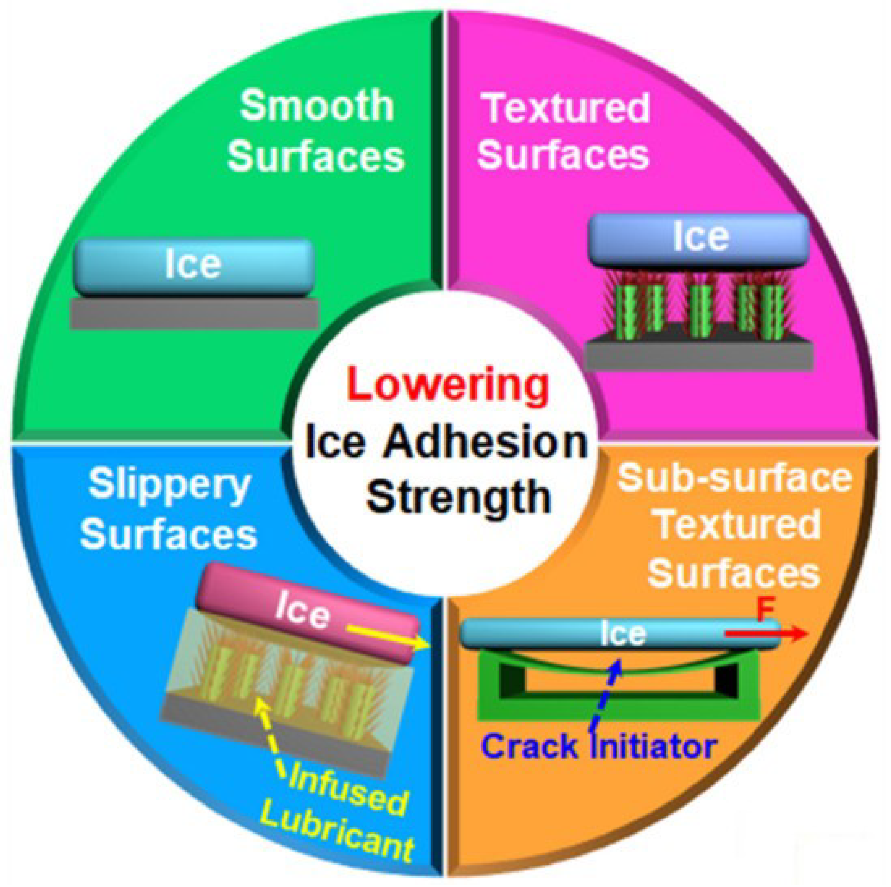
Figure 1. Overview of primary strategies for designing icephobic surfaces, categorized by surface properties: smooth, textured (e.g., hierarchical), slippery, and sub-surface textured [14].
Processes 14 00985 g001
Figure 2. (ac) Cassie–Baxter and Wenzel models of drops on rough surfaces.
Processes 14 00985 g002
Figure 3. Ice adhesion strength versus temperature for four surface categories: (a) smooth, (b) textured, (c) slippery, and (d) sub-surface textured. Data points are compiled from the literature and grouped by test method following [14]. The broad spread within each class reflects protocol dependence (ice type/formation, geometry, loading mode/rate, and failure mode) as well as true material differences, motivating standardized reporting and benchmarking [23].
Processes 14 00985 g003
Figure 4. Interfacial shear stress of various laser-treated samples as a logarithmic function of the developed interfacial area ratio ( S d r ) for four icing conditions. The non-linear trend highlights the complex relationship between surface texture and ice adhesion [26].
Processes 14 00985 g004
Figure 5. Adapted schematics of common ice adhesion testing methods: (a) horizontal shear (push test), (b) vertical shear test, (c) tensile pull-off, and (d) centrifuge. The blue elements represent ice, the gray elements represent the substrate, support, or loading fixture, the green element represents the additional support/adhesive component shown in the centrifuge schematic, and the arrows indicate the loading direction in each test configuration.
Processes 14 00985 g005
Figure 6. Mechanisms responsible for low ice adhesion on elastomeric coatings. (A) Ice adhesion strength for PDMS coatings with varying crosslink density ( ρ CL ) and with or without interfacial slippage. (B,C) Relationships between τ ice and ρ CL without (B) and with (C) interfacial slippage, revealing different scaling laws. (D) Resulting ice-reducing potential ( l * ) as a function of ρ CL [10].
Processes 14 00985 g006
Table 1. Representative wetting and ice-adhesion performance for common surface types. WCA: static water contact angle; CAH: contact-angle hysteresis; τ ice : shear ice adhesion strength at 10   ° C (approximate ranges); ARF: adhesion reduction factor relative to uncoated aluminum (baseline τ ice 200 kPa ).
Surface TypeWCACAH τ ice (kPa)ARFReference(s)
Bare aluminum (polished)≈75°high200 to 3001.0[4,27]
Smooth hydrophobic coating (e.g., PTFE)100 to 115°10 to 20°100 to 150≈2[19]
Superhydrophobic (micro-rough)150 to 160°<10°30 to 604 to 8[20,21]
Superhydrophobic (nano-rough)150 to 155°<15°50 to 803 to 5[19,28]
Soft silicone coating (low modulus)110 to 120°<20°5 to 20>10[10]
SLIPS (lubricant-infused)100 to 115° a<5°10 to 30≈10[10,24]
Hydrogel/hydrated coating≈89–95°-≈5–19°≫10[29,30]
a SLIPS typically exhibit very low hysteresis; static WCA may be moderate.
Table 2. Horizontal comparison of fabrication routes for passive icephobic surfaces: dominant mechanism levers, scalability, and typical durability limits (synthesized from [14,17,24,25]).
Fabrication RouteScalabilityIce Adhesion ( τ ice )Potential Durability
Laser TexturingMediumModerate
(∼50–100 kPa)
High
(Substrate intrinsic)
Chemical EtchingHighVery Low
(if SLIPS: <10 kPa)
Moderate
(Porosity/oxide fragility)
Spray/Sol–GelHighHigh Reduct.
(<20 kPa)
Moderate
(Binder/particle loss)
Thermal SprayHighModerate
(∼30–150 kPa)
High
(Hard ceramic/metal)
CVD/iCVDLow–MedHigh Reduct.
(Thin film)
Low–Moderate
(Thin film wear)
Molding (LIT)MediumHigh Reduct.
(<20 kPa)
Moderate
(Soft erosion/aging)
Disclaimer/Publisher’s Note: The statements, opinions and data contained in all publications are solely those of the individual author(s) and contributor(s) and not of MDPI and/or the editor(s). MDPI and/or the editor(s) disclaim responsibility for any injury to people or property resulting from any ideas, methods, instructions or products referred to in the content.