1. Introduction
With the continuous growth in the installed capacity of renewable energy generation, renewable energy sources—represented primarily by wind power—are progressively becoming a vital component of modern power systems. Due to the advantages of a smaller converter capacity rating, high operational efficiency, and flexible variable-speed constant-frequency (VSCF) control, the doubly fed induction generator (DFIG) maintains a broad application basis in onshore wind farms [
1]. However, large-scale wind power is typically integrated into relatively weak grid areas. The increased impedance from long-distance transmission and collection lines reduces the system’s short-circuit ratio (SCR), thereby significantly intensifying the dynamic interactions between the wind turbines and the grid impedance [
2]. Under weak grid conditions, wind power grid-connected systems are highly susceptible to stability issues, including subsynchronous, supersynchronous, and broadband oscillations [
3]. At the broader smart-grid level, reliable real-time monitoring and communication schemes have also been investigated to improve the detection of critical grid events [
4], further highlighting the need for robust converter operation under dynamically changing grid conditions. For grid-following DFIGs, the phase-locked loop (PLL) not only fulfills the function of synchronous phase detection but also alters the system’s equivalent impedance characteristics via coordinate transformations and current control loops, which subsequently deteriorates the system’s stability margin under weak grids [
5].
Currently, extensive research has been conducted by scholars worldwide on the stability issues of renewable energy grid-connected systems. Common analytical methods primarily include eigenvalue analysis based on state-space models, frequency-domain analysis based on transfer functions, and stability analysis based on impedance models. The state-space method can comprehensively describe the internal dynamic processes of the system, making it suitable for modal analysis and parameter sensitivity analysis; however, in scenarios involving multiple control loops and multi-converter coupling, it suffers from issues such as high model order and strong parameter dependency [
6]. The transfer function method facilitates the analysis of the impact of local control loops on stability, but its applicability is limited in multi-input multi-output (MIMO) coupled systems and scenarios with significant frequency coupling [
7].
In contrast, the impedance analysis method can characterize the dynamic interactions between the wind turbine and the grid from the perspective of terminal characteristics, and it can be combined with the Nyquist criterion to evaluate system stability [
8]. The introduction of the impedance stability criterion provided a foundational framework for the stability analysis of grid-connected converters [
9]. Subsequently, dq-frame impedance modeling methods for grid-connected voltage source converters (VSCs) have continuously evolved, providing an essential tool for analyzing the interactive effects among control loops, the PLL, and grid impedance [
10]. Further investigations into the dq-frame small-signal impedance characteristics of three-phase grid-connected converters have offered a valuable reference for impedance modeling and stability analysis under weak grid conditions [
11].
Regarding DFIG grid-connected systems under weak grid conditions, existing studies have demonstrated that the dynamics of the PLL are crucial factors affecting the system’s impedance characteristics and stability margin. The utilization of complex transfer functions and transfer matrices to describe three-phase dynamic systems has provided a theoretical foundation for impedance modeling under frequency coupling conditions [
12]. Systematic reviews of the structures and dynamic characteristics of three-phase PLLs have pointed out that PLL parameters significantly influence the dynamic response of grid-connected control systems [
13]. Investigations into the modeling and control of DFIGs under unbalanced grid conditions have demonstrated that grid disturbances can affect the rotor-side dynamic characteristics through the control loops [
14]. Studies on the subsynchronous interactions between wind farms and the grid in weak AC systems have revealed that the dynamic coupling between renewable energy grid-connected systems and weak grid impedance may induce oscillation issues [
15]. Furthermore, a unified impedance model for grid-connected VSCs was proposed, noting that the PLL and outer-loop control alter the equivalent impedance matrix and consequently affect system stability [
16]. To address the stability analysis of grid-connected converters with coupling terms, a generalized impedance stability criterion has also been proposed [
17].
Regarding stability enhancement, existing research has primarily focused on PLL parameter tuning, virtual impedance compensation, voltage-disturbance compensation, and supplementary impedance reshaping. A symmetrical PLL structure was developed to improve impedance-modeling accuracy and stability analysis for grid-connected converters in weak grids [
18]. An improved virtual-inductance controller considering PLL dynamics was proposed to enhance DFIG stability [
16], while voltage-disturbance compensation was introduced to reshape the terminal characteristics through an additional voltage-related control path [
19]. More closely related to the present work, supplementary compensation methods have been developed to mitigate PLL-induced frequency coupling and adverse impedance characteristics by acting on the rotor-current dynamics or converter control path [
20,
21]. These studies demonstrate the effectiveness of targeted impedance compensation without fundamentally changing the primary power- and current-control objectives.
A concise comparison of representative impedance-reshaping approaches is provided in
Table 1.
To address these limitations, this paper proposes an integrated Double-PLL-Based impedance-reshaping strategy for DFIGs under grid-frequency deviations. In this terminology, the proposed strategy consists of two coordinated parts: a supplementary rotor-current compensation path and a Double-PLL-Based relative-phase-angle generator. The supplementary path directly reshapes the adverse impedance characteristics by compensating the coupling from the point of common coupling (PCC) disturbance to the rotor-side control output, whereas the main and auxiliary PLLs generate a frequency-adaptive relative-angle signal for this compensation path. Therefore, the additional PLL alone is not regarded as an independent impedance-reshaping mechanism. Unlike the closest single-PLL implementation, the proposed strategy constructs the compensation signal from the relative dynamics of two PLL estimates rather than from the deviation between one PLL and the fixed nominal-frequency reference. This integrated architecture avoids continuous compensation drift under persistent frequency deviations and reduces reliance on a dedicated high-pass filter. Its effectiveness is evaluated through generalized Nyquist analysis, MATLAB/Simulink (2020b) time-domain simulations, and hardware-in-the-loop (HIL) experiments. The main contributions of this paper are summarized as follows:
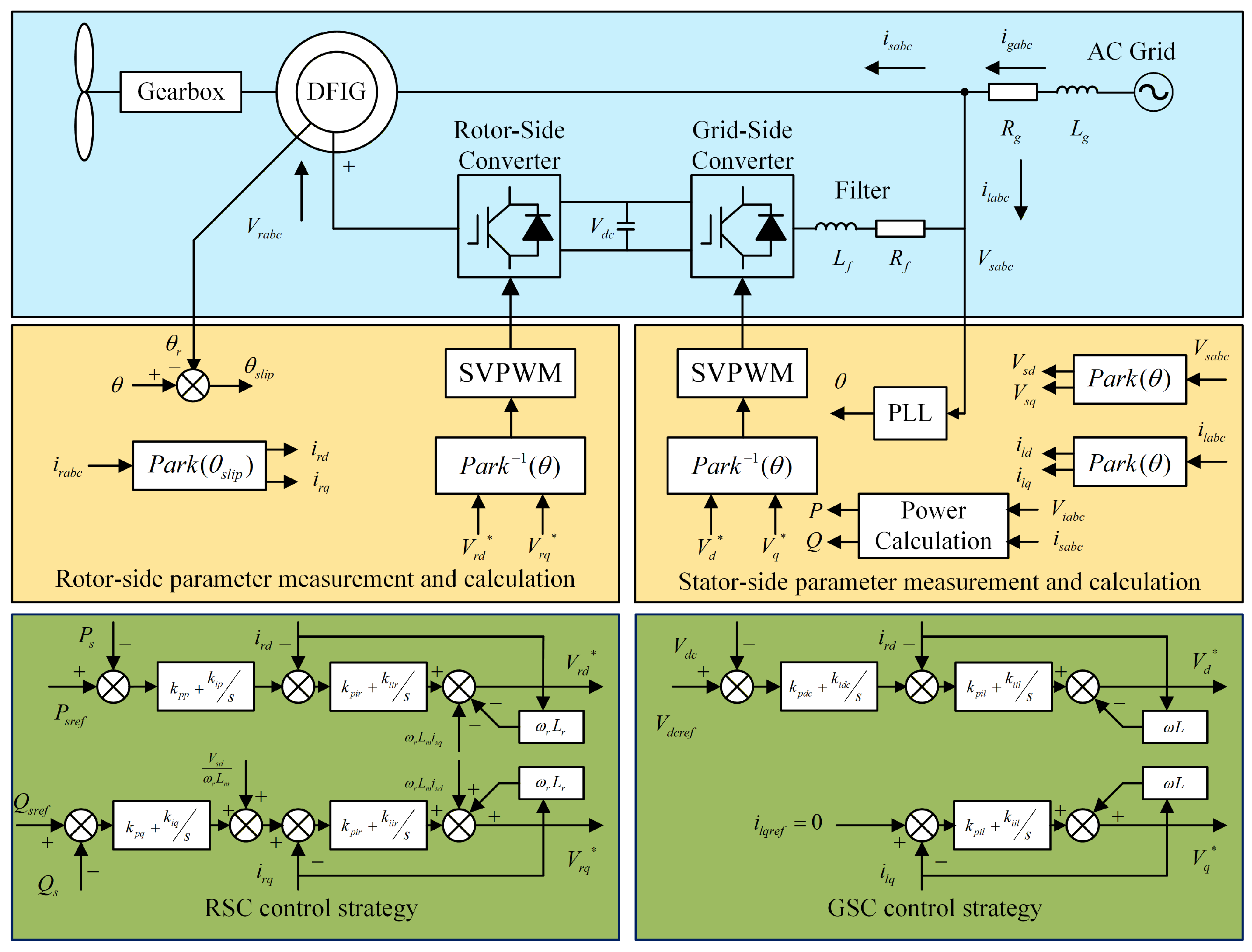
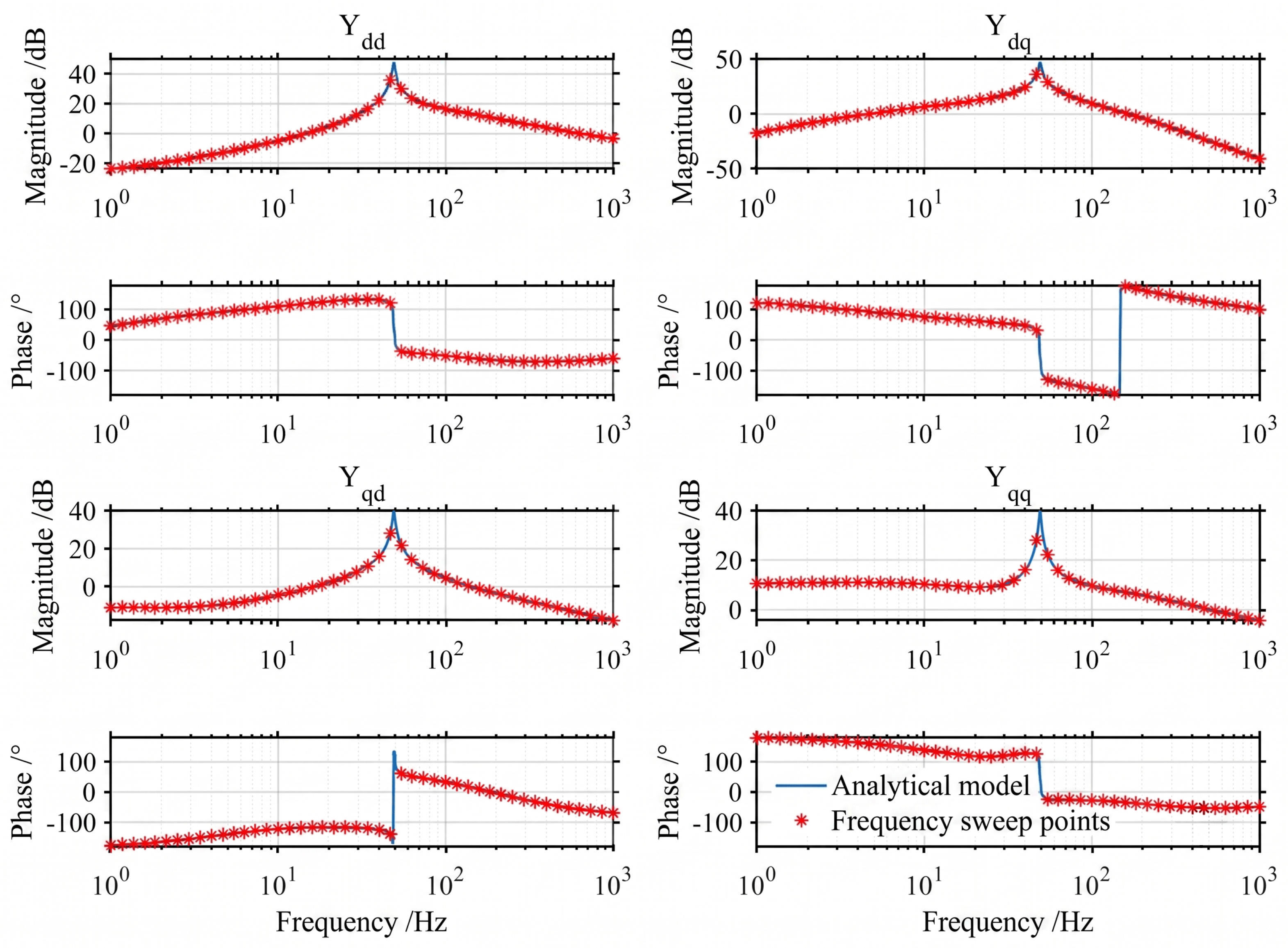
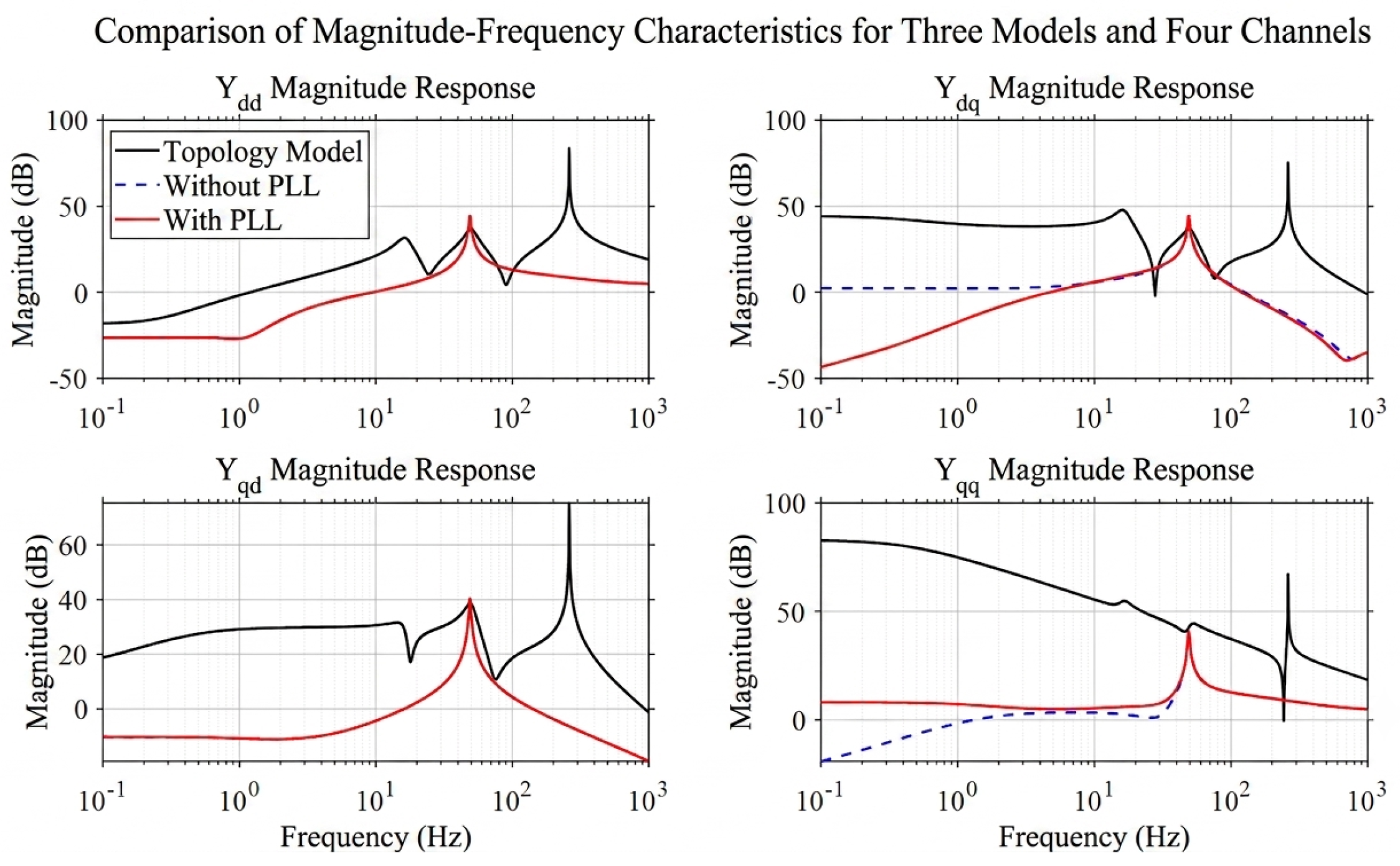
1. Admittance Modeling and Mechanism Analysis: A complete admittance model of the DFIG grid-connected system considering the RSC, GSC, DC link, and PLL dynamics is established, and the critical PLL-related coupling channel that degrades the impedance characteristics and stability margin under weak-grid conditions is identified.
2. Impedance Reshaping via Supplementary Compensation: A rotor-current compensation path is constructed to act on the identified adverse coupling channel and reshape the DFIG impedance characteristics within the target frequency range without changing the primary power- and current-control objectives.
3. Double-PLL-Based Frequency-Adaptive Implementation: The relative phase angle between the main and auxiliary PLLs is integrated into the rotor-current compensation path to form the complete Double-PLL-Based impedance-reshaping strategy. This implementation replaces the compensation signal referenced to the fixed nominal frequency, prevents continuous drift under persistent frequency deviations, and reduces reliance on a dedicated high-pass filter.
4. Impedance Reshaping Method for DFIGs
4.1. DFIG Impedance Reshaping Method Based on Feedforward Compensation
The preceding analysis demonstrates that the negative impedance characteristics introduced by the PLL significantly diminish the stability margin of the grid-connected DFIG system under weak grid conditions, constituting one of the primary causes of system instability. To address this issue, a common approach is to attenuate the influence of PLL dynamics on the system’s impedance characteristics by decreasing the PLL bandwidth or reducing the relevant control parameters, thereby improving the grid-connected stability. However, this method inherently sacrifices synchronization tracking speed and dynamic response capability in exchange for an increased stability margin. Consequently, it often leads to a sluggish system response during grid disturbances, operating condition variations, and fault recovery processes, making it difficult to simultaneously satisfy the requirements for both dynamic performance and stable operation.
By introducing a feedforward compensation loop, targeted adjustments are made to the magnitude and phase distribution of the DFIG output impedance, driving the system’s impedance characteristics within the frequency bands of interest toward a direction favorable for stable operation. Rather than directly modifying the main structure and fundamental control objectives of the original controller, this method mitigates the adverse effects of the PLL’s negative impedance effect on grid-connected stability by reconstructing the impedance shaping path via supplementary compensation signals.
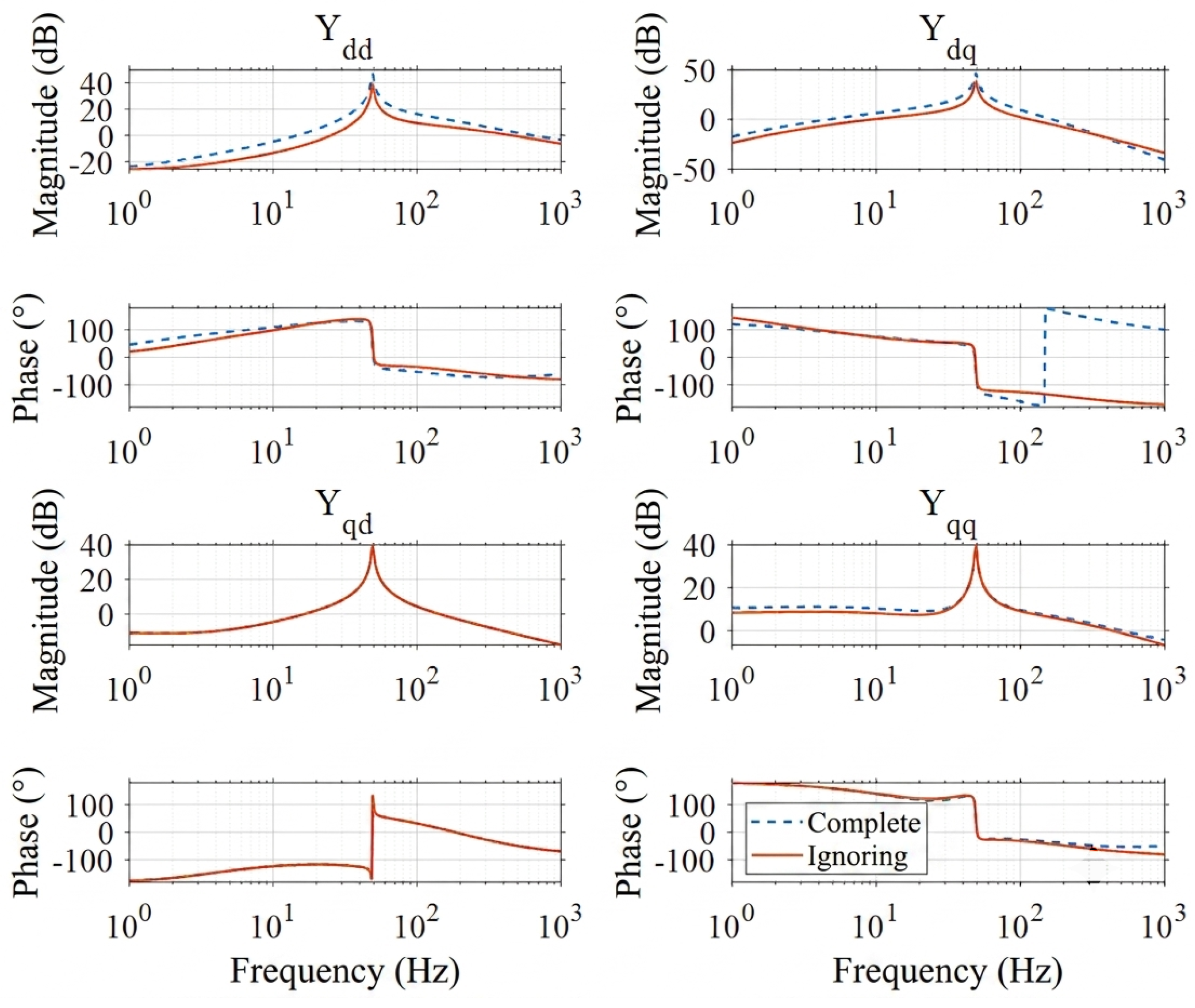
The term in the DFIG admittance model, which represents the perturbation effect of voltage fluctuations at the PCC on the rotor-side voltage of the DFIG, is a primary factor contributing to the system’s instability under weak-grid conditions. Therefore, it is imperative to redesign the control strategy to counteract the adverse impact on system stability caused by the negative-impedance loop introduced by this component. This matrix evidently exhibits an asymmetrical structure and is entirely associated with the q-axis voltage perturbation. Furthermore, following the incorporation of the PLL, the expression for resembles a second-order integral term; at lower frequencies, the low-frequency rotor current acquires an excessively large gain, leading to a deviation of the rotor current from its expected value. Consequently, a second-order high-pass filter (HPF) is incorporated into the feedforward control path to suppress the DC and low-frequency bias components of the phase-angle compensation signal.
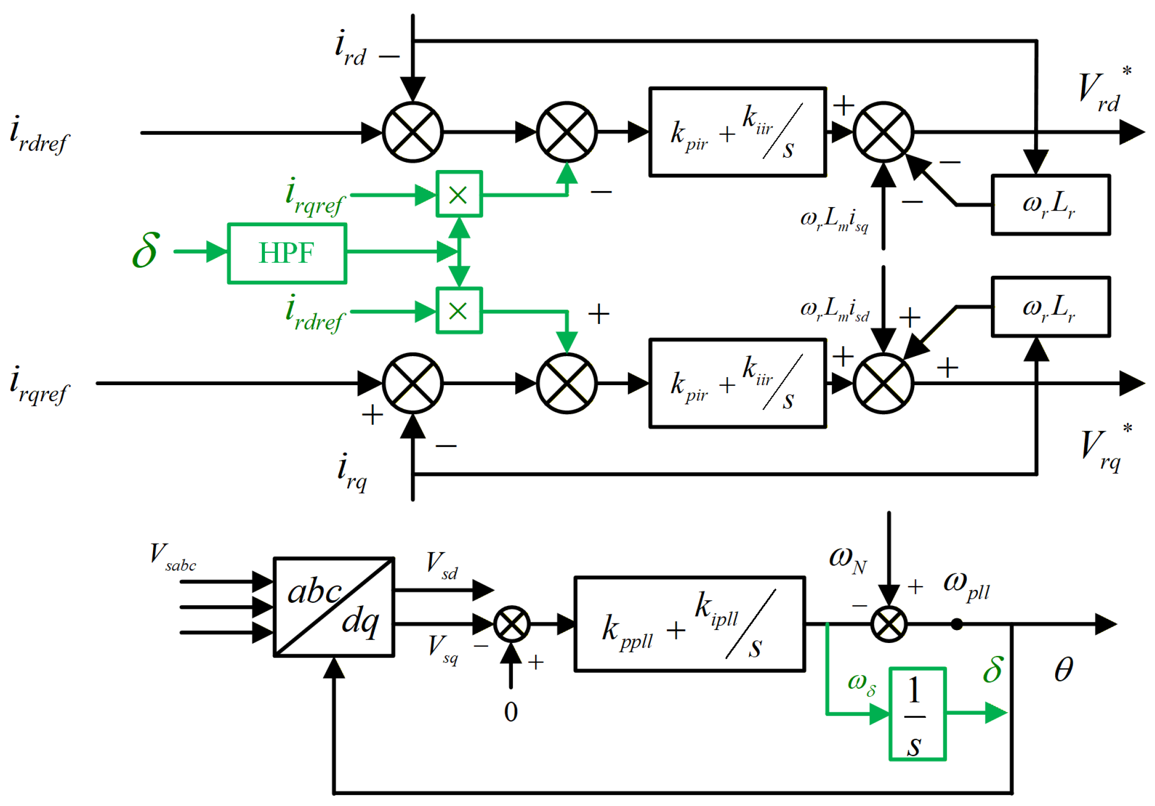
In
Figure 9, firstly, the phase angle deviation signal
is obtained from the output of the PLL. Next, a high-pass filter is utilized to extract its AC component associated with oscillations. Finally, this dynamic deviation is combined with the reference current channel to generate an additional compensation term, which is subsequently injected into the rotor-side voltage control loop. Since this compensation quantity inherently originates from the synchronization phase deviation, it can more directly reflect the influence path of the PLL dynamics on the system’s impedance characteristics.
The scheme illustrated in
Figure 9 can essentially be regarded as a small-signal feedforward correction based on phase angle deviation. Its physical significance lies in the following: when weak grid disturbances induce a dynamic shift in the output phase angle of the PLL, this shift will react on the rotor-side control output via coordinate transformations and controller coupling paths, thereby deteriorating the impedance characteristics of the DFIG. Conversely, the proposed compensation branch partially counteracts this original adverse effect by introducing an additional control variable related to this phase angle deviation.
4.2. DFIG Impedance Reshaping Method Considering Grid Frequency Deviation
However, the aforementioned method exhibits limitations under grid-frequency deviations. A high-pass filter is required to suppress the DC and low-frequency bias components of the phase-angle compensation signal. If a lower cutoff frequency is used, can cause continuous error accumulation and ultimately destabilize the system. Conversely, increasing can intensify frequency coupling.
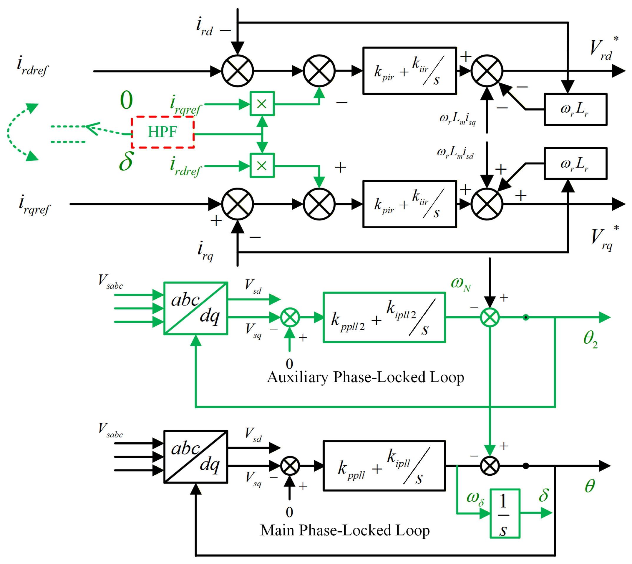
To address this issue, this paper proposes a Double-PLL-Based impedance-reshaping strategy for the DFIG, as shown in
Figure 10.
Compared with the conventional single-PLL implementation, the proposed Double-PLL-Based impedance-reshaping strategy introduces an auxiliary PLL in addition to the original main PLL. The main PLL maintains the synchronous reference frame for the DFIG vector controller, whereas the auxiliary PLL is used only to generate the relative phase-angle signal for the impedance-reshaping branch; both PLLs are driven by the PCC voltage.
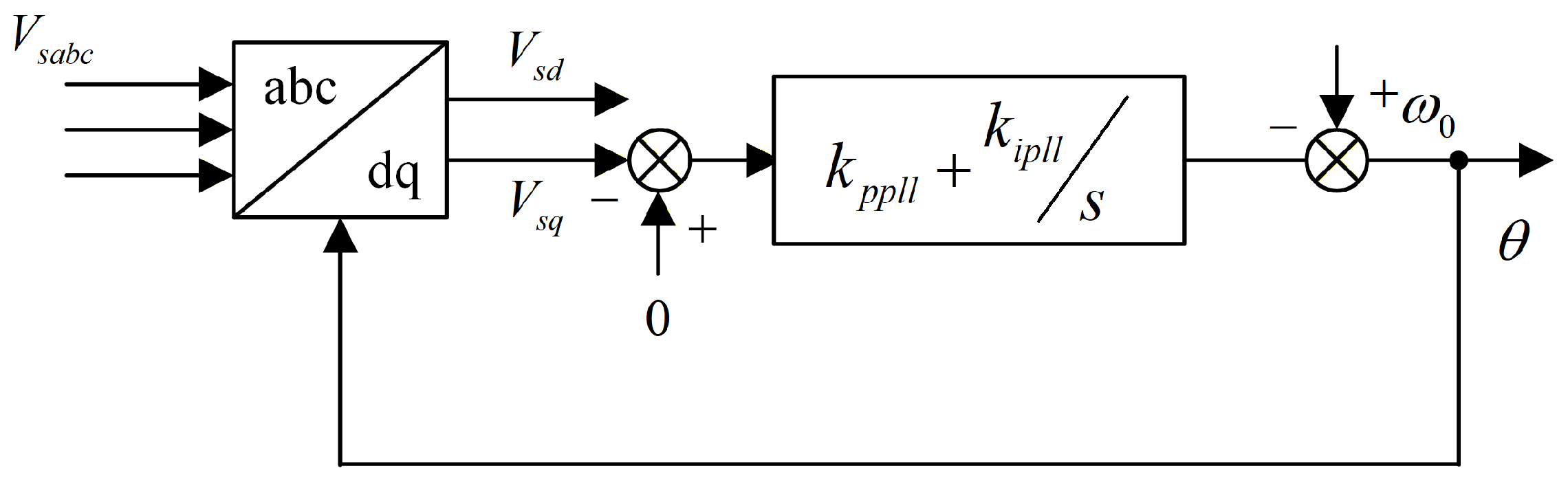
The PLL error signal
can be expressed as:
After passing through the PI controller of the PLL:
Following integration, the deviation
can be expressed as:
Let the angle deviation
be the difference between the two angles; after small-signal linearization,
can be expressed as:
Under the condition of a single PLL, utilizing the rated power frequency
as the reference frequency, the compensation angle can be expressed as:
When a deviation exists in the actual grid frequency, i.e.,
:
If the frequency deviation persists, will continuously accumulate, resulting in a drift in the compensation amount.
However, if the output
of the auxiliary PLL is adopted as the reference frequency, the compensation angle can be rewritten as:
For the
ith stable PLL, define
. Its closed-loop frequency-tracking transfer function is
, which satisfies
. Therefore,
For and , this transfer function has no pole at the origin and all its poles are in the left-half plane; hence, is bounded for any bounded grid-frequency deviation. In particular, a constant frequency deviation gives , while a grid-frequency ramp with rate r gives the finite value . Thus, the relative-angle signal does not continuously accumulate, provided that both PLLs remain locked within the small-signal operating range.
For systematic tuning, the closed-loop denominator of the
ith PLL (
for the main PLL and
for the auxiliary PLL) is matched to the standard second-order form
. The corresponding PI gains are selected as
where
is the steady-state
d-axis PCC voltage. The main-PLL parameters retain the original synchronization performance, while the auxiliary-PLL parameters are selected to provide adequate relative-angle dynamics within the target impedance-reshaping range. The bandwidth separation should not be excessive, because identical PLL dynamics yield a weak compensation signal, whereas an overly fast auxiliary PLL increases sensitivity to measurement noise and harmonics.
For the normalized PLL input, p.u. Under this condition, the auxiliary-PLL gains listed in Table 2, namely and , correspond to and . By comparison, the main-PLL parameters give and . Therefore, the auxiliary PLL has a lower characteristic frequency and provides slower and smoother tracking dynamics than the main PLL. The final parameter selection is verified using the generalized Nyquist criterion for the complete system.
From an implementation perspective, the proposed strategy introduces one additional PI-PLL, including an integrator, a PI controller, and a relative-angle calculation. Therefore, its computational burden and number of dynamic states are slightly higher than those of the single-PLL implementation. However, the main-PLL parameters remain unchanged, and the auxiliary PLL can be tuned directly through the desired damping ratio
and natural frequency
using (
54). In contrast, the conventional method additionally requires coordinated selection of the HPF cutoff frequency and filter parameters to balance drift suppression and frequency-coupling performance. Hence, the proposed method does not claim a lower total implementation cost; rather, it replaces HPF-related tuning trade-offs with a structured auxiliary-PLL tuning procedure.
The two PLLs interact through the relative angle and the supplementary compensation path. The auxiliary PLL does not alter the main synchronization loop directly; instead, is injected into the rotor-current compensation branch, which subsequently affects the PCC dynamics. Therefore, the final parameter selection should also preserve adequate stability margin for the complete Double-PLL-Based impedance-reshaping system.
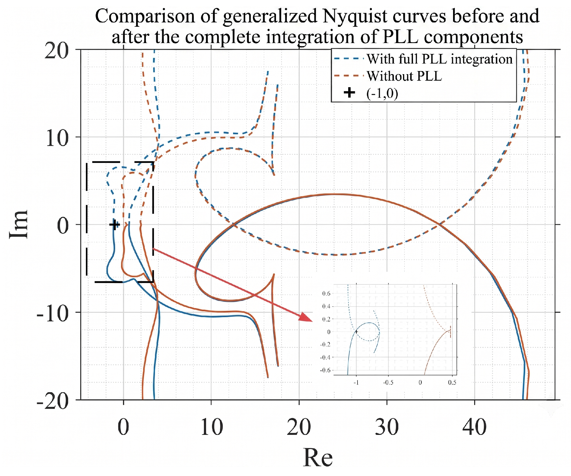
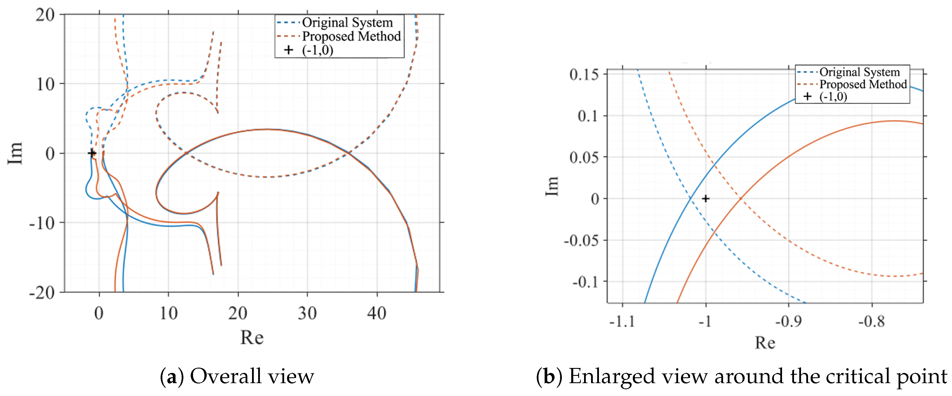
Figure 11 compares the generalized Nyquist eigenloci of the original system and the system using the proposed Double-PLL-Based method. The enlarged view shows that the proposed method shifts the critical eigenloci away from the critical point
. After compensation, the eigenloci do not encircle
; since the open-loop system has
, the proposed system has
and hence
, confirming closed-loop stability according to the generalized Nyquist criterion. This result demonstrates that the supplementary compensation branch reshapes the DFIG output impedance, mitigates the adverse influence of PLL dynamics, and improves the system stability margin.
5. Simulation and HIL Experimental Results
The Double-PLL-Based implementation replaces the original method of formulating the compensation amount relative to a fixed nominal-frequency reference with an approach based on the relative synchronous angle difference, thereby enhancing the adaptability of the control strategy to grid-frequency deviations. The parameters in
Table 2 are selected for simulations of a representative 1.5 MW, 690 V DFIG system and are not manufacturer data. The rated and electrical parameters define the operating point, whereas the controller gains are selected for the considered simulations; the PLL gains follow the tuning principle in
Section 4.2. Under weak-grid conditions (SCR=2), the wind turbine utilizes the parameters provided in
Table 2.
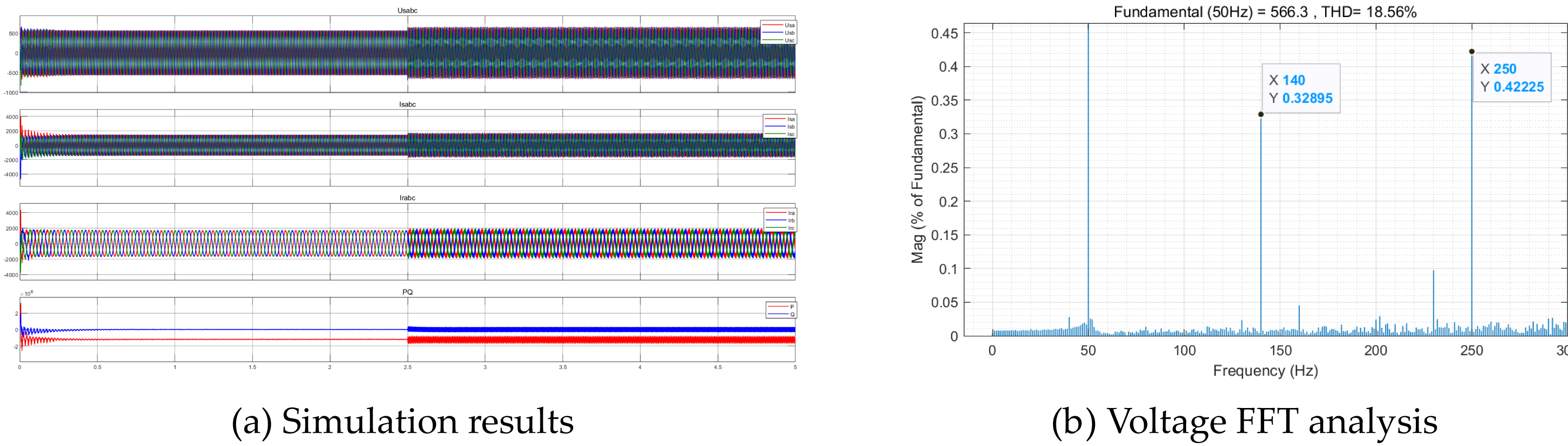
At 2.5 s, the system SCR is altered to 1.95, and the resulting waveforms are illustrated in
Figure 12. Upon changing the system short-circuit ratio at 2.5 s, the harmonics of the system waveforms increase significantly, and the active and reactive powers exhibit apparent oscillations, indicating that the system has become unstable due to oscillations. The FFT analysis of the system voltage reveals oscillation components at 140 Hz and 250 Hz. This indicates that, under weak-grid conditions, the system is highly susceptible to oscillations induced by
q-axis voltage disturbances in the PLL. Therefore, the proposed method targets PLL-induced oscillations within the 10–300 Hz range, including the dominant supersynchronous components at 140 Hz and 250 Hz observed in this case.
Table 2.
Simulation parameters of the representative DFIG system.
Table 2.
Simulation parameters of the representative DFIG system.
| Parameter | Symbol | Value |
|---|
| Rated capacity | | 1.5 MW |
| Rated voltage | | 690 V |
| Rated active power | | 1.2 MW |
| Rated reactive power | | 0 Mvar |
| Rated frequency | | 50 Hz |
| DC-link capacitance | | 1 × 10⁻² F |
| DC-link voltage | | 1150 V |
| Filter resistance | | 3.03 × 10⁻⁵ Ω |
| Filter inductance | | 2.02 × 10⁻⁵ H |
| Stator resistance | | 9.52 × 10⁻³ Ω |
| Rotor resistance | | 5.08 × 10⁻³ Ω |
| Magnetizing inductance | | 2.93 × 10⁻³ H |
| Stator leakage inductance | | 1.82 × 10⁻⁴ H |
| Rotor leakage inductance | | 1.62 × 10⁻⁴ H |
| Power loop proportional gain | | 0.02 |
| Power loop integral gain | | 0.002 |
| Rotor current loop proportional gain | | 1.2 |
| Rotor current loop integral gain | | 10 |
| Main PLL proportional gain | | 10 |
| Main PLL integral gain | | 100 |
| Auxiliary PLL proportional gain | | 5 |
| Auxiliary PLL integral gain | | 50 |
| DC voltage loop proportional gain | | 6 |
| DC voltage loop integral gain | | 400 |
| Grid-side current loop proportional gain | | 10 |
| Grid-side current loop integral gain | | 100 |
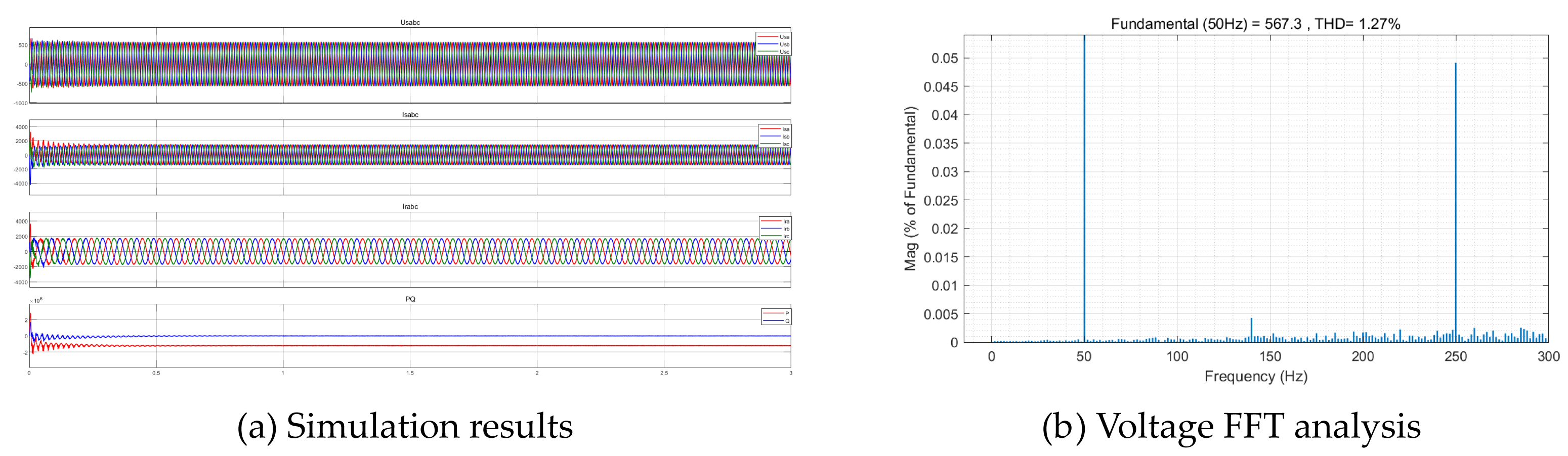
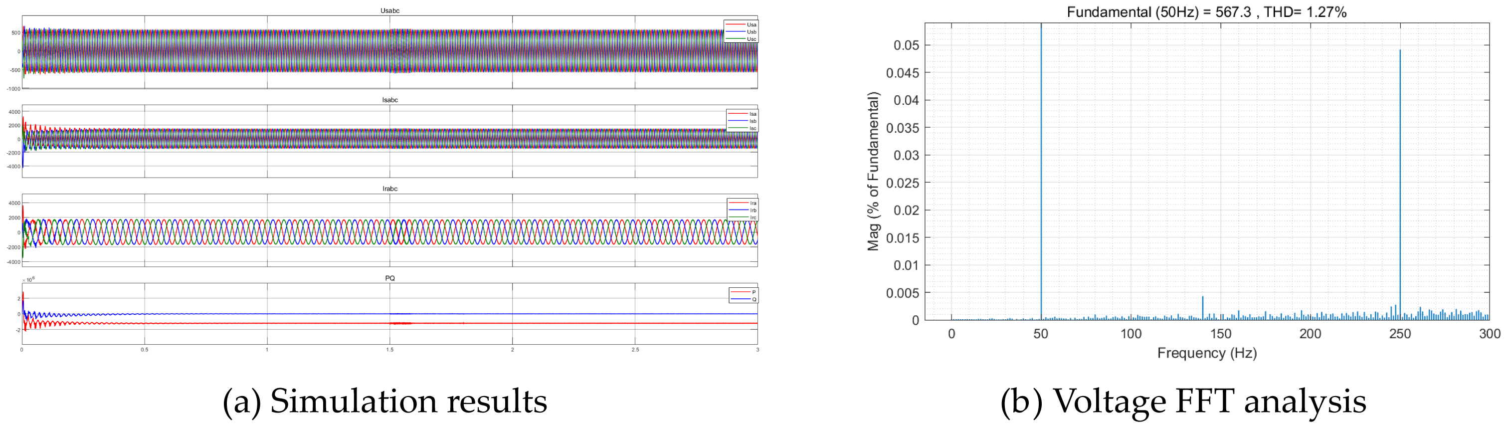
Under the proposed control strategy, when the SCR drops from 2 to 1.9 at 1.5 s, the simulation results in
Figure 13 show no obvious harmonic amplification. The voltage harmonic content remains below 5%. When the SCR drops to 1.8 at 1.5 s,
Figure 14 shows that the system returns to stable operation after a brief oscillation of approximately 0.1 s, and the steady-state voltage harmonic content remains below 5%. The quantitative comparison in
Table 3 therefore indicates that the proposed strategy retains adaptability under weak-grid conditions.
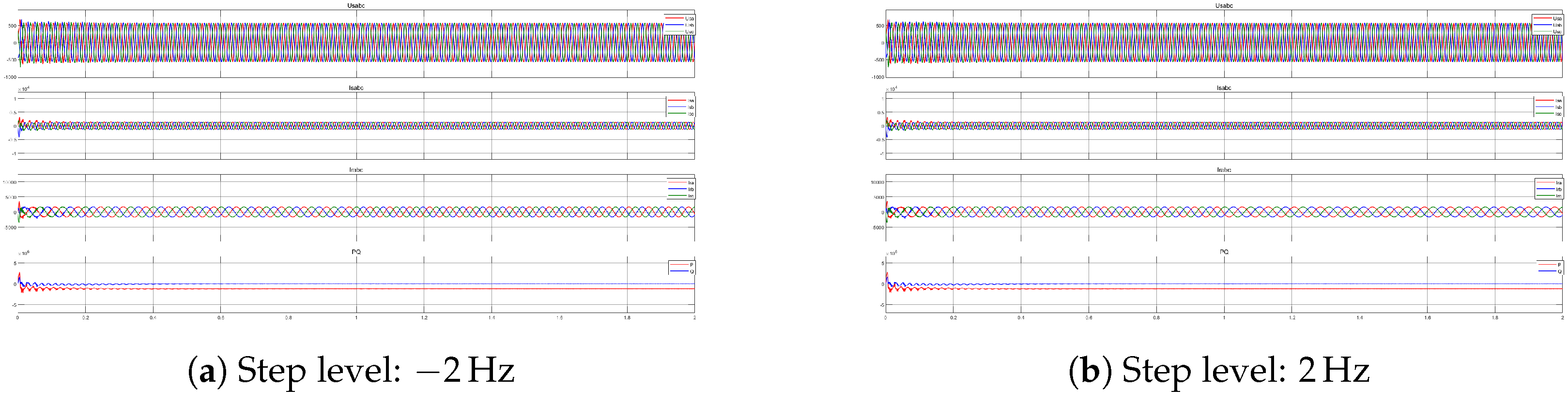
To demonstrate the adaptability of the proposed control strategy to grid-frequency deviations, simulations were conducted under three frequency-variation scenarios: continuous frequency drop, continuous frequency rise, and step frequency change. The results were compared with those obtained using the rotor-current feedforward compensation method [
21], as detailed in
Table 4.
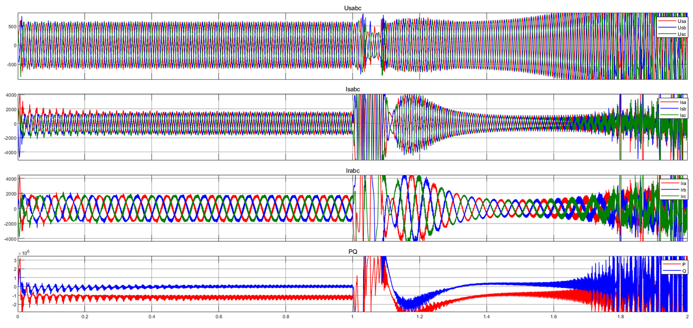
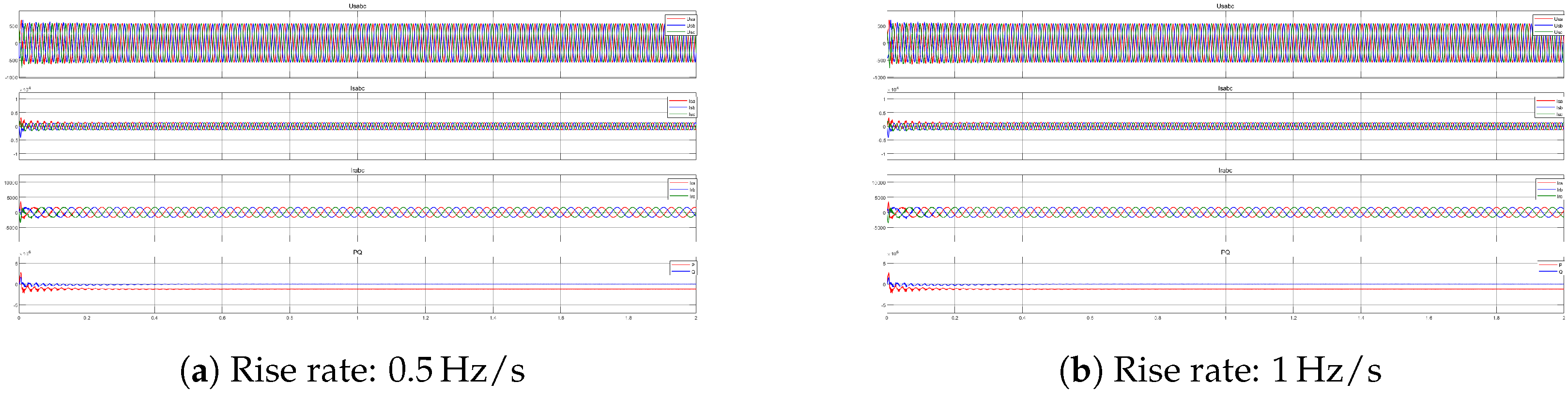
Figure 15 shows the response of the system using rotor-current feedforward compensation under a continuous grid-frequency drop. The grid frequency decreases linearly from 50 Hz at
to 49.5 Hz at
, corresponding to a drop rate of 0.5 Hz/s. With
, the gain coefficient
, and the quality factor
, the nonzero frequency deviation causes the compensation error to accumulate continuously, ultimately resulting in instability and oscillation.
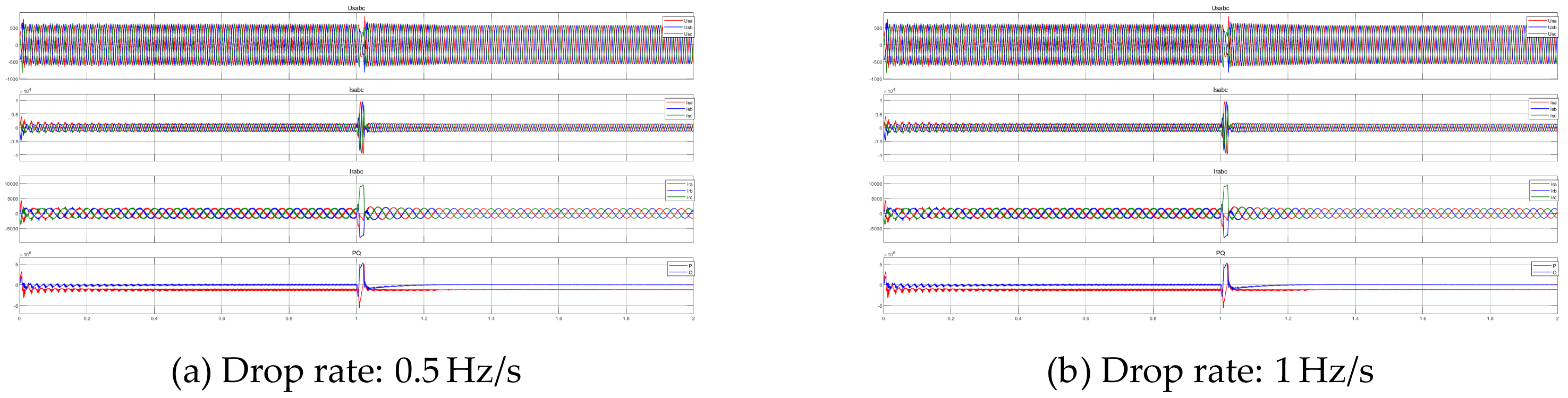
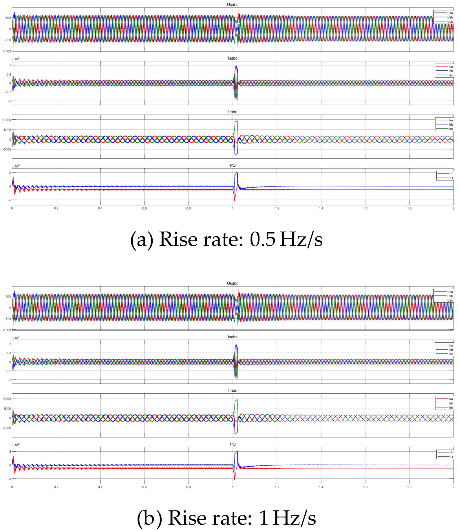
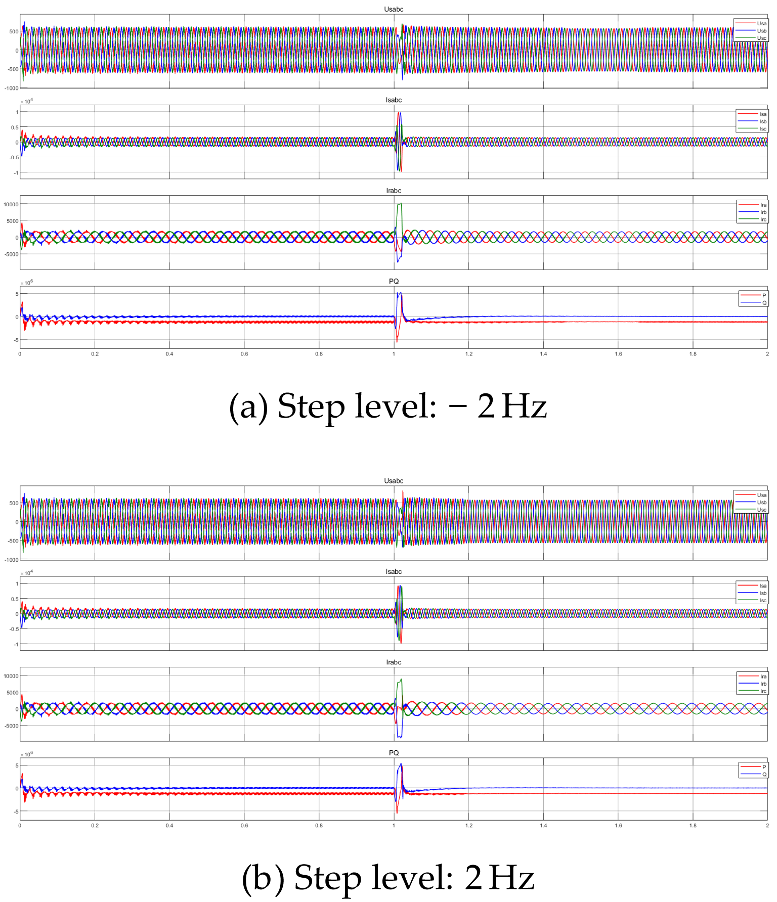
Figure 16,
Figure 17 and
Figure 18 show the results obtained using rotor-current feedforward compensation under continuous frequency drop, continuous frequency rise, and step frequency change after increasing
. In all cases, the disturbance applied at
causes brief but pronounced transients in the stator-voltage, stator-current, and rotor-current waveforms. The active and reactive powers also exhibit short spikes before rapidly returning to steady values without sustained oscillation.
This indicates that the filtering stage can more effectively mitigate the low-frequency bias components induced by frequency deviations, allowing the compensation branch to act primarily on dynamic disturbance components and thus preventing the continuous accumulation of system errors. Consequently, the impedance reshaping strategy can function properly, and the system waveforms recover to a stable state relatively quickly. This demonstrates that, after appropriately increasing , the single-PLL-based impedance reshaping strategy can still achieve a certain degree of stability enhancement under frequency deviation conditions.
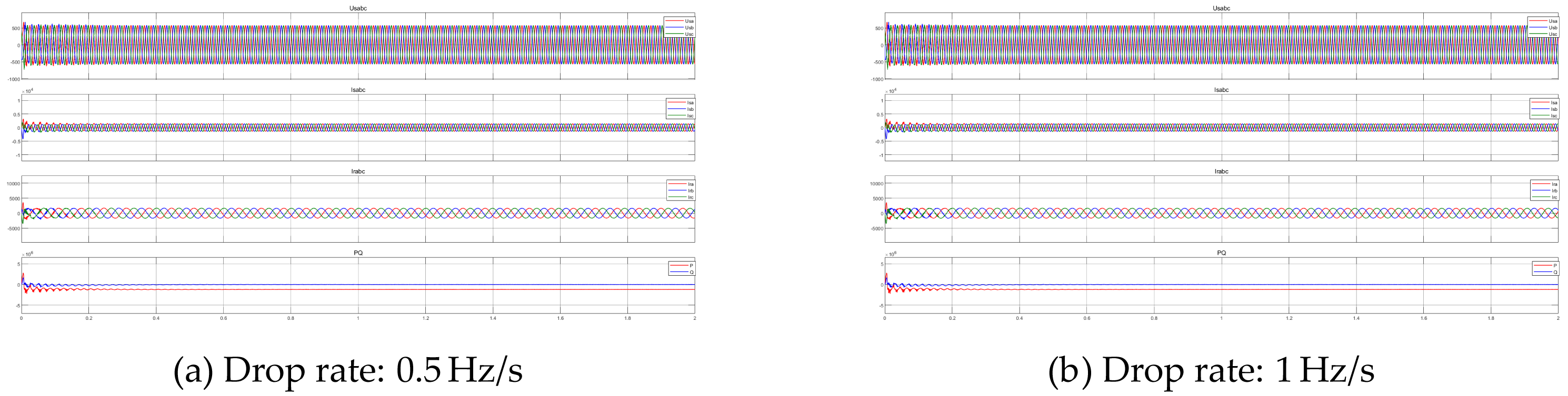
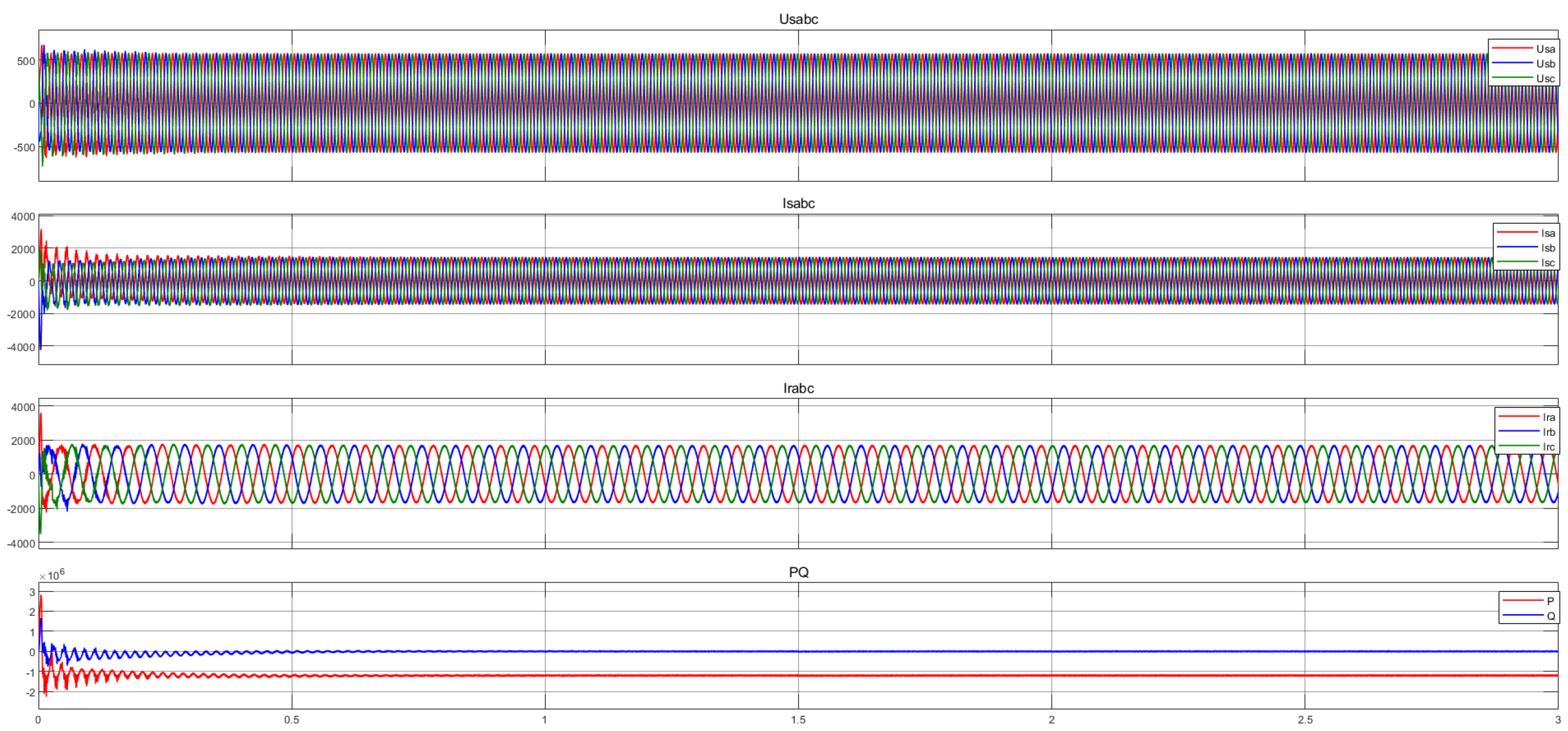
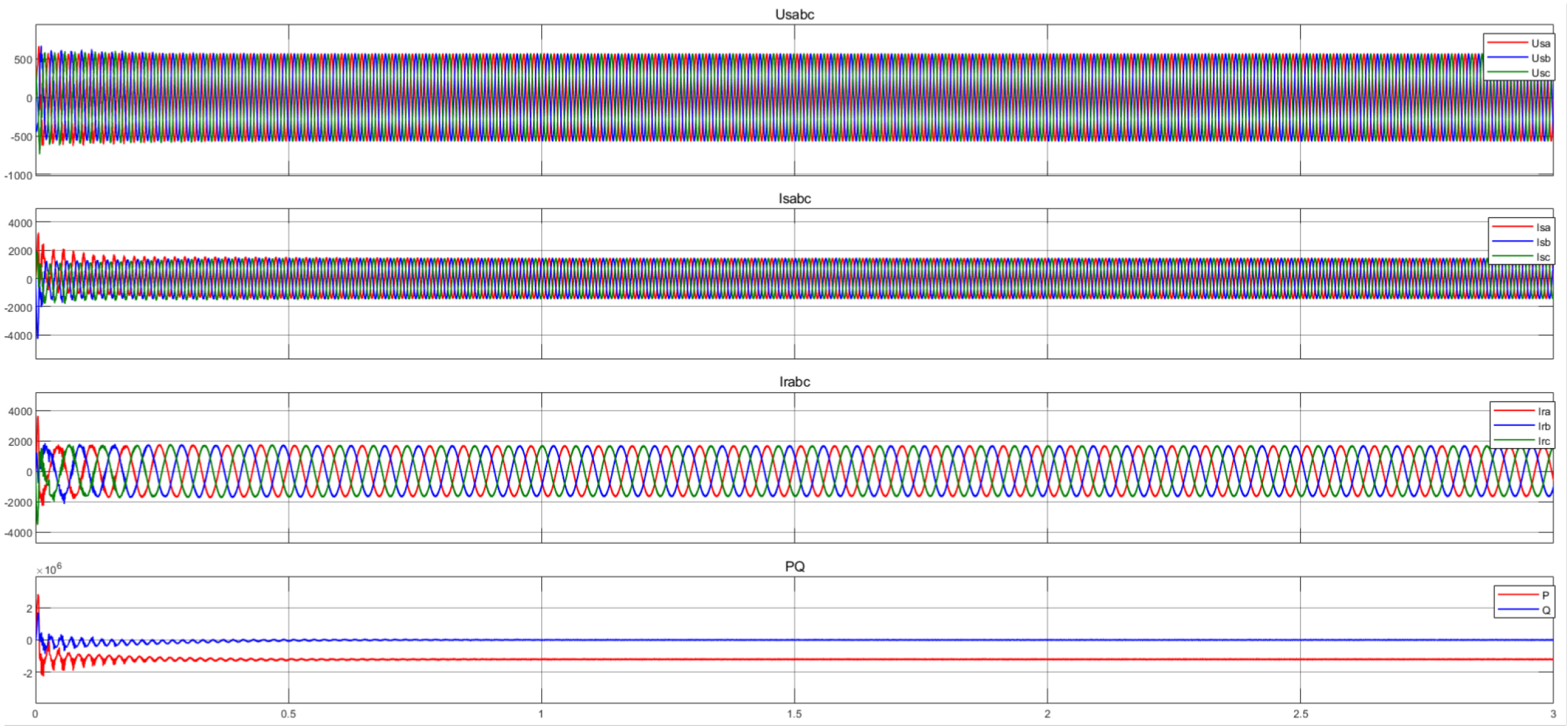
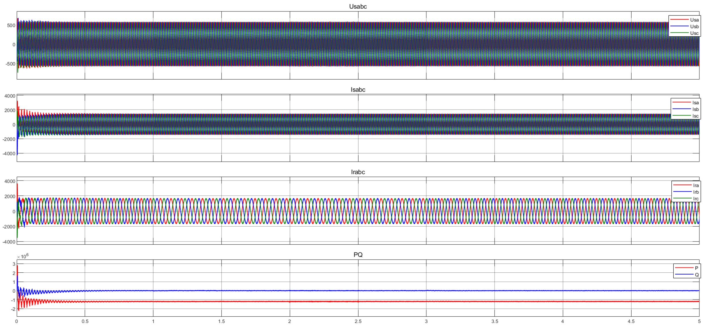
Figure 19,
Figure 20 and
Figure 21 present the simulation results of the proposed method under scenarios of continuous grid frequency drop, continuous frequency rise, and step frequency changes (step-up or step-down). The simulation results reveal that when the frequency disturbance occurs at
, the three-phase stator voltage, stator current, and rotor current waveforms of the system maintain a highly smooth, symmetrical sinusoidal profile throughout the entire simulation period under both continuous frequency variation and step disturbance scenarios. Unlike the rotor-current feedforward compensation method, the voltage and current waveforms under the proposed method exhibit no visible transient distortion, amplitude fluctuation, or harmonic amplification throughout the process. The active and reactive powers rapidly converge to their steady-state values.
These results demonstrate that the proposed control strategy maintains stable operation and suppresses pronounced transients under the grid-frequency variations considered in this study, thereby improving its adaptability to off-nominal-frequency conditions.
It is worth noting that, after the Double-PLL-Based impedance-reshaping strategy is introduced, the compensation branch no longer constructs the control variable from the deviation of the main PLL relative to a fixed nominal-frequency reference. Instead, it uses the relative deviation between the main and auxiliary PLLs for adaptive correction. Because both PLLs track the actual grid frequency in steady state, their steady-state frequency difference is zero, and the relative-angle signal does not accumulate continuously under grid-frequency deviations. Consequently, the compensation signal primarily reflects system dynamics without introducing a steady-state bias into the control channel. This feature eliminates the need for a dedicated high-pass filter for compensation-drift suppression and avoids the associated filter-tuning trade-off.
The aforementioned simulation results demonstrate that the proposed method exhibits strong robustness under scenarios of weak grids and frequency variations. To further investigate its performance when the internal control parameters change, the following simulation tests were conducted.
Figure 22 shows the system waveforms before and after changing the current-loop parameters. At
and
, these parameters are stepped to 1.2 and 0.8 times their nominal values, respectively. No obvious deterioration is observed in the waveforms, and the system remains stable throughout the test, demonstrating the robustness of the proposed method to current-loop parameter variations.
Figure 23 presents the simulated system waveforms before and after changing the PLL parameters. At
and
, the PLL parameters are stepped to 1.2 and 0.8 times their nominal values, respectively. The waveforms exhibit no obvious deterioration, sustained oscillation, or pronounced power overshoot, and the system remains stable throughout the test. These results demonstrate the robustness of the proposed control strategy under the considered PLL-parameter variations.
Under weak grid conditions, multiple operating conditions that cause system instability may occur simultaneously. Therefore, it is necessary to evaluate the robustness of the proposed method under complex operating conditions. This paper considers the following complex scenario: At
, the frequency steps to 52 Hz, and the SCR decreases from 2 to 1.8; at
, the frequency undergoes a step decrease of 2 Hz, and the current loop parameters abruptly step to 1.2 times their nominal values; at
, the PLL parameters drop to 80% of their nominal values. Under these conditions, the simulation results of the system are illustrated in
Figure 24.
To further validate the simulation results in
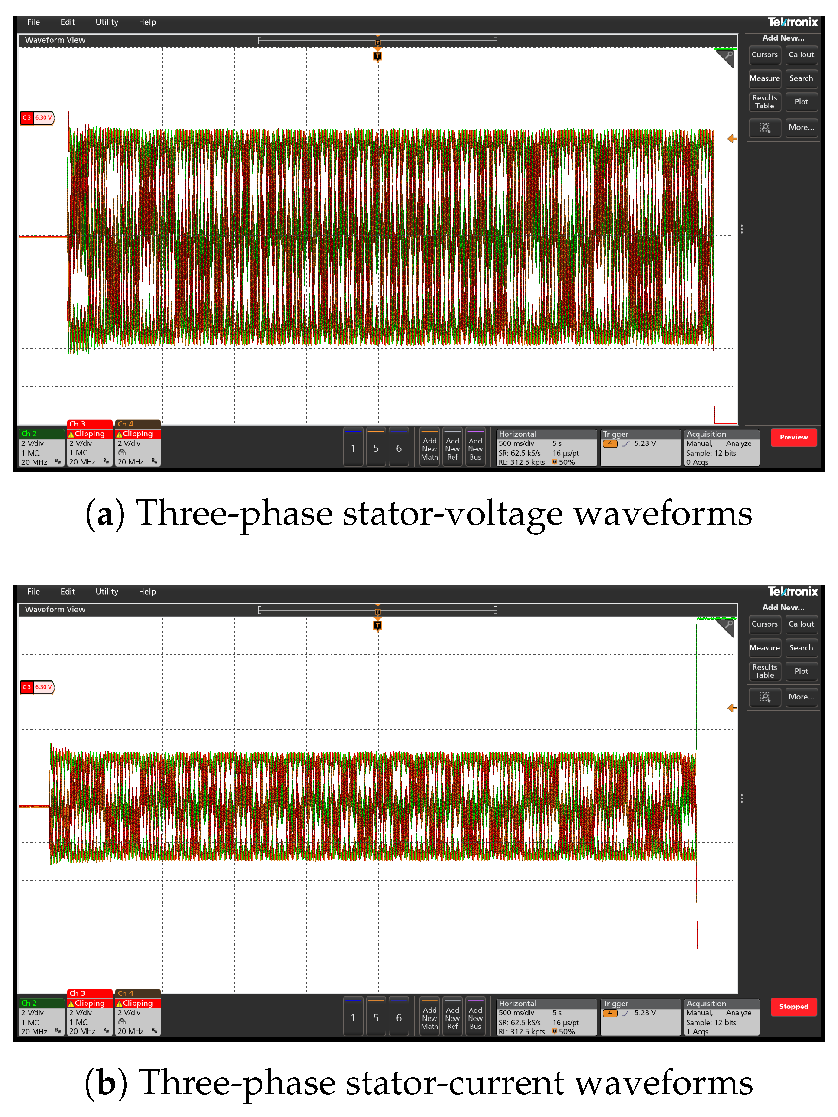
Figure 24, an HIL experiment was performed using the same PLL-parameter variation sequence. The measured three-phase stator-voltage and stator-current waveforms are shown in
Figure 25. Following the PLL-parameter variations, both waveforms remain balanced and exhibit no sustained oscillatory growth, which is consistent with the simulation results and confirms the robustness of the proposed strategy under the considered PLL-parameter perturbations.