Article

Aerodynamic Performance of Steam Turbine Blades with Influence of Tip Seal Leakage Flow

School of Energy and Power Engineering, Northeast Electric Power University, Jilin 132012, China
*
Author to whom correspondence should be addressed.
Processes 2026, 14(17), 2728; https://doi.org/10.3390/pr14172728
Submission received: 21 July 2026 / Revised: 23 August 2026 / Accepted: 24 August 2026 / Published: 26 August 2026

Abstract

Tip seal leakage in shrouded steam turbines can significantly affect the aerodynamic performance of downstream blade rows. An unsteady three-dimensional numerical model of a 1.5-stage high-pressure steam turbine is established using ANSYS CFX (ANSYS2021) with the SST k–ω turbulence model. Tip seal clearances of 1.0, 1.5, and 1.9 mm are investigated using the Q-criterion and vorticity transport equation to characterize leakage-vortex evolution and its interaction with the mainstream. The results show that increasing tip seal clearance strengthens leakage flow and expands its interaction region. The expansion term exhibits a relatively stronger influence on vorticity variation near the seal teeth, whereas the vortex stretching term plays a significant role in leakage-vortex evolution near the seal inlet, outlet, and cavity. Leakage vortices interact with the rotor wake, intensifying velocity gradients and aerodynamic loss, with pronounced flow distortion near 85% rotor span. The disturbance is further transported to the downstream stator, causing marked variations in flow angle, circumferential velocity, and static pressure in the upper-span region. At 95% and 99% blade heights, pronounced differences in suction-surface static pressure occur within the forward 80% of the chord length. These findings clarify the aerodynamic consequences of tip seal leakage and its downstream effects.

1. Introduction

The tip clearance between the rotor blade shroud and turbine cylinder inevitably generates steam leakage flow in shrouded steam turbines. Driven by the pressure difference between the pressure and suction surfaces of the blade, the leakage flow passes through the labyrinth seal and subsequently interacts with the mainstream in the blade passage. This interaction modifies the local velocity and pressure distributions, distorts the wake and secondary-flow structures, and increases aerodynamic losses. The resulting leakage vortices can also be transported into downstream blade rows, thereby affecting their inlet flow conditions and aerodynamic performance. Therefore, understanding the formation, evolution, and downstream effects of tip seal leakage flow is important for the aerodynamic design and efficiency improvement of large-capacity steam turbines.
Extensive experimental and numerical investigations have been conducted on tip leakage flow and its influence on turbine aerodynamic performance. Sjolander and Amrud [1] experimentally investigated the effect of tip clearance on blade loading in a planar turbine cascade and demonstrated the aerodynamic influence of tip clearance. You et al. [2] employed large-eddy simulation (LES) to investigate the effect of tip-gap size on tip-leakage flow and showed that the clearance size strongly affects the development of leakage vortices. Yamamoto [3] investigated endwall flow and loss mechanisms in a turbine cascade with blade-tip clearance and demonstrated that leakage flow can substantially modify the endwall secondary-flow structure and associated losses. These studies established the fundamental relationship between tip clearance, leakage-vortex development, and aerodynamic loss, but mainly focused on individual blade rows or simplified cascade configurations.
In practical multi-stage turbines, leakage flow is strongly affected by the unsteady interaction between adjacent blade rows. Gao and Zheng [4] numerically investigated unsteady endwall flow interactions in 1.5-stage shrouded and unshrouded turbines and showed that flow unsteadiness modifies endwall secondary-flow structures and associated losses. Behr [5] experimentally investigated rotor tip leakage and secondary flow in a one-and-a-half-stage high-pressure axial turbine and examined their influence on turbine aerodynamic performance. Cao et al. [6] investigated the interaction between rim-seal flow and the main flow in an axial turbine using experimental and numerical methods and demonstrated the importance of unsteady effects in describing sealing-flow/mainstream interactions. Although rim-seal flow differs from rotor tip-seal leakage, these studies demonstrate the importance of sealing-flow-induced unsteadiness in multi-stage turbine aerodynamics. However, the detailed transport mechanisms of leakage vortices and their direct relationship with downstream aerodynamic loss were not systematically resolved.
The spatial and temporal evolution of leakage vortices has also received considerable attention. Pogorelov et al. [7] employed LES to resolve the transient characteristics and spatial development of tip-leakage flow. Kim and Ahn [8] investigated leakage flow in a stepped labyrinth seal using LES and compared its performance with RANS approaches, highlighting the complex flow structures inside labyrinth-seal cavities. Yang et al. [9] analyzed tip-leakage flow in a transonic turbine cascade using unsteady numerical simulations and quantitatively described the evolution of leakage-vortex trajectory and intensity. Zhou and Zhou [10] investigated the unsteady interaction between tip-leakage vortices and flow separation and associated vortex breakdown with aerodynamic loss. These studies have improved the understanding of leakage-vortex structure and unsteady behavior; however, most emphasized vortex identification, trajectory, or overall flow characteristics rather than the physical mechanisms governing vortex evolution and their contribution to aerodynamic loss.
The vorticity transport equation provides a useful framework for identifying the mechanisms governing vortex development. Xu et al. [11] investigated tip-leakage cavitating flow under different tip-clearance sizes using LES and employed the vorticity transport equation to examine the contributions of vortex stretching, dilatation, and baroclinic torque to vortex development. Their results demonstrated that the relative importance of these mechanisms varies with tip-clearance size, while the stretching term remained dominant for the investigated cases. Although this work provides an important methodological reference for analyzing the relationship between tip clearance and vorticity transport, it investigated cavitating flow around a NACA0009 hydrofoil instead of steam flow in a high-pressure turbine. In addition, the analysis mainly focused on tip-leakage-vortex development, without considering its subsequent interaction with turbine wakes and aerodynamic loss generation. Therefore, the applicability of this approach to the complex-flow environment of large-capacity shrouded steam turbines requires further investigation.
Vorticity-transport analysis has also been applied to turbine seal and secondary-flow problems. Rusch et al. [12] analyzed the unsteady vorticity field in an axial turbine rotor labyrinth cavity and related vorticity-transport mechanisms to secondary-flow effects and loss generation. Barmpalias et al. [13] further investigated vorticity dynamics in an axial turbine and related vortex stretching to secondary-flow loss generation. More recently, Kan et al. [14] combined vorticity-transport analysis with entropy-production analysis to investigate the energy-loss mechanism associated with tip-leakage flow and showed the importance of vortex stretching in leakage-vortex evolution. These studies demonstrate the potential of vorticity-transport analysis for connecting vortex dynamics with loss generation. However, the complete evolution of tip-seal leakage vortices from a multi-tooth labyrinth seal through rotor-wake interaction to downstream stator distortion in a high-pressure, large-capacity shrouded steam turbine remains insufficiently understood.
Various sealing configurations have also been developed to suppress leakage and reduce the associated aerodynamic penalties. Vakili et al. [15] investigated advanced labyrinth seals for steam turbine generators and demonstrated the potential of seal-geometry modification for reducing leakage. Cangioli et al. [16] developed a thermo-elastic bulk-flow model for labyrinth seals in steam turbines and considered the influence of operating conditions on seal behavior. Zeng et al. [17] investigated the effects of squealer-tip geometry on tip-leakage flow and loss and showed that tip geometry can substantially alter leakage-vortex development. Cao et al. [18] optimized labyrinth-seal structural parameters using orthogonal experiments and regression analysis. Li et al. [19] investigated steam excitation forces and vorticity distributions induced by tip-seal leakage flow. Li et al. [20] further examined the influence of double-side labyrinth seals on the aerodynamic performance of a transonic shrouded turbine stage. These studies demonstrate that seal geometry and clearance are important design parameters, but the downstream aerodynamic consequences of leakage vortices remain less systematically addressed.
The interaction between leakage flow, wakes, and downstream blade rows is another important mechanism affecting turbine aerodynamic performance. Qian et al. [21] investigated the interaction between tip leakage flow and blade wakes and demonstrated that their coupling affects turbine aerodynamic performance. Zhao and Wang [22] developed an analytical model for predicting leakage rate and pressure distribution in an axial labyrinth seal, while Yang [23] proposed a loss-assessment method for fluid-curtain labyrinth seals. These studies contribute to the understanding of leakage characteristics and seal-related losses, but do not establish a direct relationship between vorticity-transport mechanisms, rotor-wake loss, and downstream stator distortion.
Therefore, although previous studies have clarified the effects of tip clearance on leakage-vortex development and demonstrated the applicability of vorticity-transport analysis to vortex dynamics and loss generation, their combined application to high-pressure, large-capacity shrouded steam turbines remains limited. In particular, the links between leakage-vortex evolution, rotor-wake interaction, aerodynamic loss, and downstream stator distortion under different tip clearances remain insufficiently understood.
Accordingly, this study investigates a 1.5-stage configuration representative of the high-pressure section of a 1000 MW ultra-supercritical steam turbine with a typical labyrinth tip seal. Unsteady simulations are performed for tip-seal clearances of 1.0, 1.5, and 1.9 mm. The Q-criterion and vorticity transport equation are used to characterize leakage-vortex evolution and quantify the contributions of vortex stretching, expansion, and baroclinic torque, while the aerodynamic loss production rate is employed to relate vortex interaction to rotor-wake loss and downstream stator distortion. The results provide further insight into the aerodynamic consequences of tip-seal leakage in large-capacity steam turbines.

2. Methodology

2.1. Computational Model and Boundary Conditions

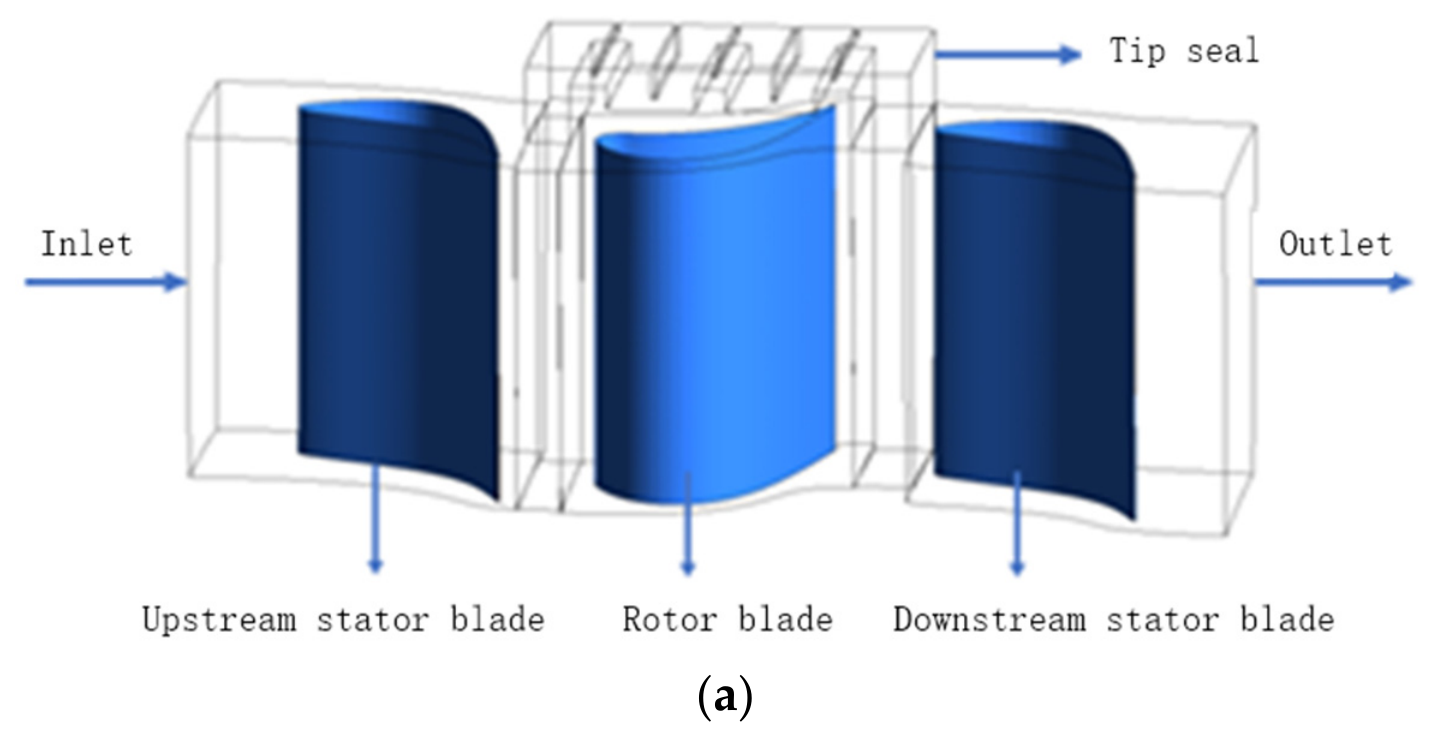
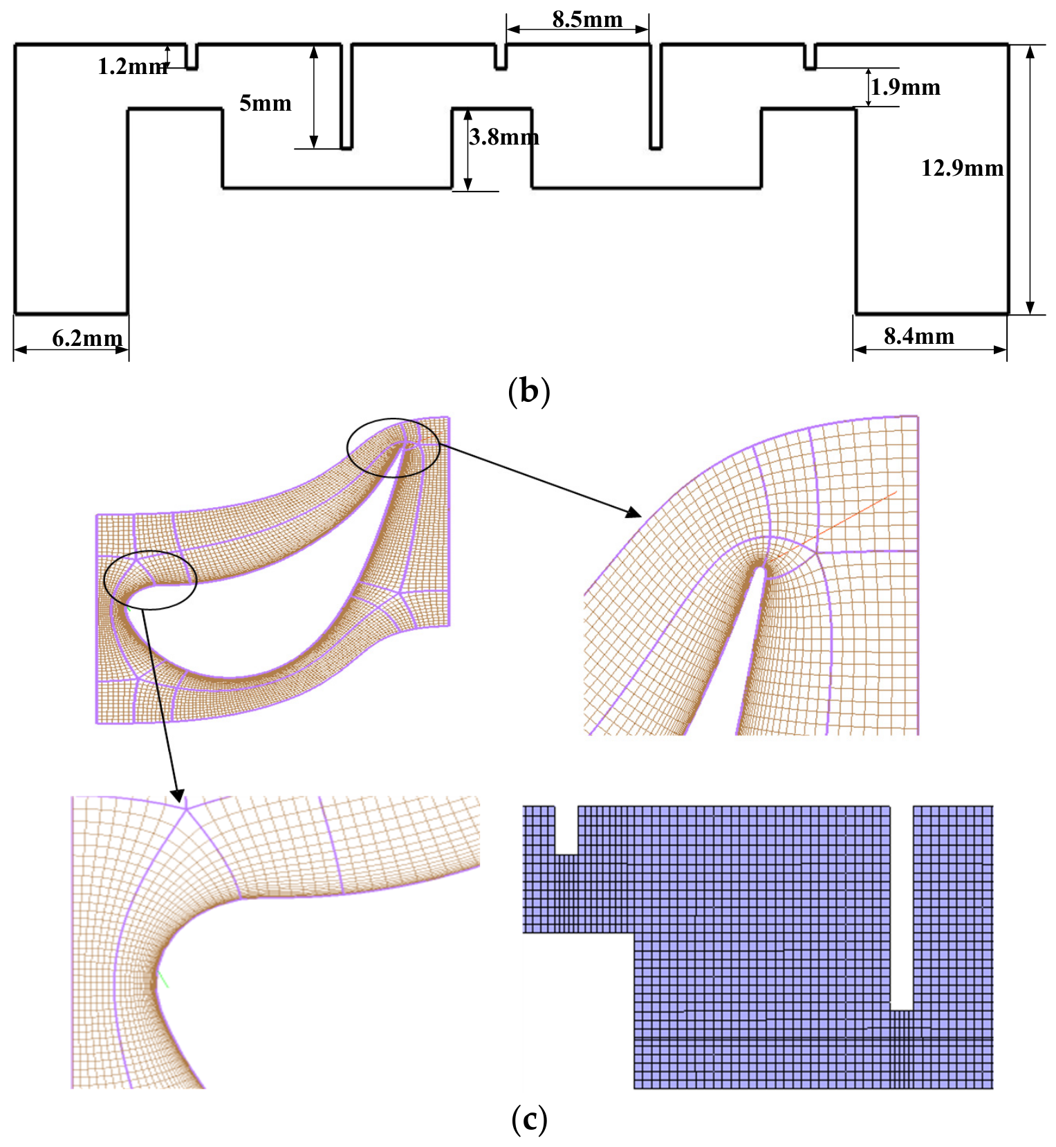
The stator and rotor blades used in this study are three-dimensional twisted blades, consistent with the structural features of full-scale large-capacity steam turbines. The 1.5-stage computational model derived from the high-pressure cylinder of a 1000 MW ultra-supercritical steam turbine is shown in Figure 1a, with 68 stator blades and 68 rotor blades arranged in a single stage. Figure 1b presents the schematic layout of the labyrinth seal at the rotor blade tip, and Figure 1c shows the local meshing details of the blade passage and tip labyrinth seal.
This stage adopts a typical 50% reaction design. Table 1 lists the overall geometric parameters of the computational model, and Table 2 summarizes the spanwise geometric data of the rotor blade at three representative sections (blade root, mid-span and blade tip), including chord lengths and inlet/outlet flow angles. The rotor Zweifel loading coefficient decreases gradually from 0.716 at the blade root to 0.672 at the blade tip.
To improve the accuracy of the numerical simulation, the model is divided into blocks for grid generation. ANSYS ICEM (ANSYS Fluent, 2022 R1, ANSYS Inc., Canonsburg, PA, USA) and Turbo Grid are used to create a structured hexahedral mesh for the labyrinth seal, the axial gap section between the rotor blades and the adjacent two stator blades, and the structure of the 1.5-stage blade. The boundary layer of the blade is locally refined, and an “HOH” topology structure is employed around the blade.
The boundary conditions correspond to rated operating conditions. The flowing working fluid is superheated steam, and the data is sourced from IAPWS-IF97 [24]. Uniform inlet total pressure and total temperature boundary conditions are specified at the domain inlet for simplification. The inlet extension section is reserved upstream of the first stator blade row to develop the incoming boundary layer automatically, so an independent inlet endwall boundary layer profile is not manually imposed. The inlet turbulence intensity is set to 5%, and the turbulence length scale is defined as 5% of the stator blade span according to typical steam turbine inlet flow characteristics. The inlet total temperature is 544.2 °C, the inlet total pressure is 18.96 MPa, and the outlet static pressure is 16.46 MPa. In the labyrinth seal, the stator blades are set as no-slip adiabatic solid wall surfaces. The rotor blades are set as rotating surfaces with a speed of 3000 r/min. The steady-state interface between the rotor, stator and seal is modeled using the Frozen Rotor approach, and each domain is set as a rotating periodic surface. The unsteady interface between the rotor and stator is modeled using the Transient Rotor Stator approach. The residual convergence accuracy of the continuity equation is 1 × 10⁻⁴, while the residual convergence accuracy of the momentum equation and energy equation are both 1 × 10⁻⁶. The calculated sub-time step size is 1 × 10⁻⁵ s.
Mesh independence validation was conducted using turbine isentropic efficiency as the evaluation criterion, which is given in Equation (1) as follows [4]:
η   =   ( 1     T t , o u t T t , i n ) / [ 1     ( P t , o u t P t . i n ) ( γ     1 ) / γ ]
where η is the turbine isentropic efficiency. Tt,in is the inlet total temperature of the stage, K. Tt,out is the outlet total temperature of the stage, K. Pt,in is the inlet total pressure of the stage, Pa. Pt,out is the outlet total pressure of the stage, Pa. γ is the adiabatic index; for superheated steam, γ is taken as 1.35.
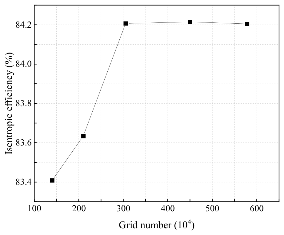
A grid-independence study was performed using the turbine isentropic efficiency as the evaluation criterion. Five mesh densities ranging from 1.40 to 5.80 million cells were tested under the design tip-clearance condition of 1.9 mm. As shown in Figure 2, the isentropic efficiency increases from 83.41% to 84.21% as the mesh density increases from 1.40 to 3.05 million cells. For tip clearances of 1.0, 1.5, and 1.9 mm, the corresponding isentropic efficiencies are 86.10%, 85.44%, and 84.21%, respectively. Further refinement to 4.50 and 5.80 million cells changes the efficiency only to 84.22% and 84.20%, respectively. The corresponding leakage mass flow rates through the tip seal are 0.105 kg/s, 0.151 kg/s, and 0.206 kg/s for tip clearances of 1.0 mm, 1.5 mm, and 1.9 mm, respectively. The increase in leakage mass flow with clearance enlargement indicates enhanced leakage intensity and provides a direct explanation for the strengthened interaction between leakage flow and mainstream flow discussed in subsequent sections. The difference between the 3.05-million-cell mesh and the finest mesh is only 0.01 percentage point, indicating that further mesh refinement has a negligible effect on the calculated isentropic efficiency. Therefore, the 3.05-million-cell mesh is adopted for both the steady-state and unsteady simulations to balance numerical accuracy and computational cost. The y+ values in the tip-leakage region are mainly within the range of 30–120; therefore, scalable wall functions are employed to model the near-wall turbulent boundary layer instead of directly resolving the viscous sublayer.
A reasonable turbulence model should be selected for the accuracy of the numerical calculation, so the standard model, RNG model, and SST model in CFX are evaluated. The total pressure loss coefficient is used to make a comparison among them, which can be written as follows:
C pt   =   P t , i n     P t P t , i n     P t , o u t
where Pt is the area-averaged total pressure inside the flow field, Pa. Cpt is the total pressure loss coefficient.
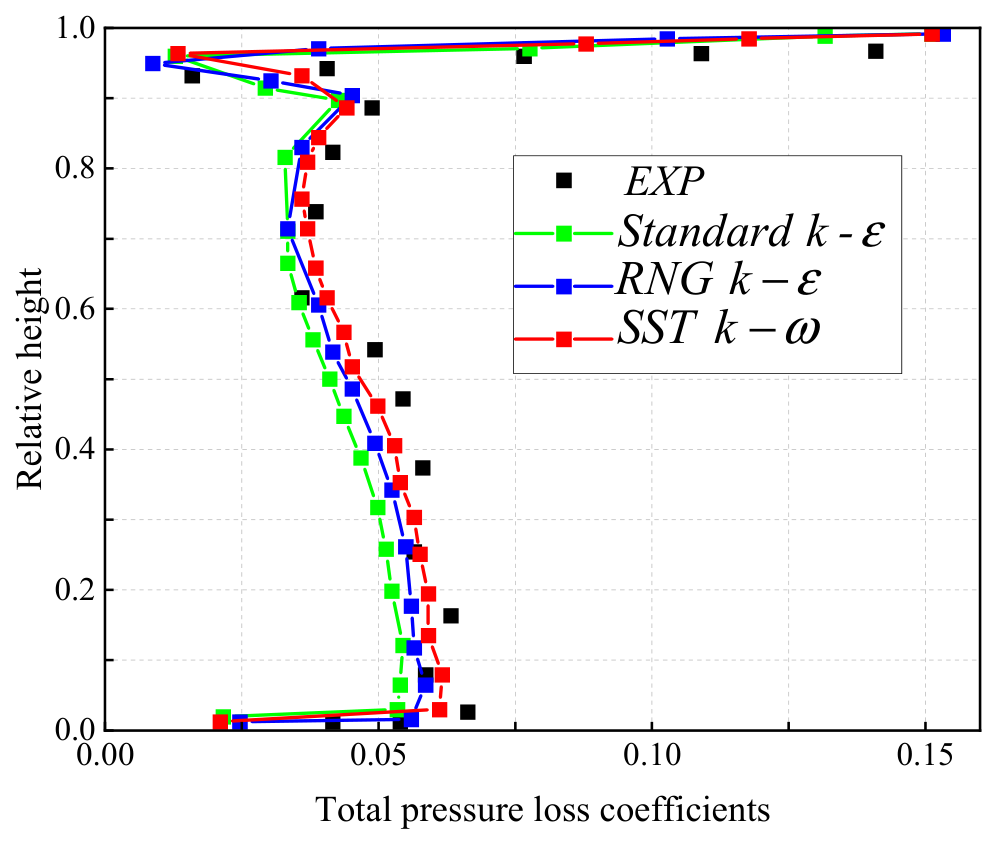
Figure 3 compares the spanwise distribution of the total pressure loss coefficient at the rotor outlet predicted by the three turbulence models with the experimental data reported by Behr [5]. Among the three models, the SST k–ω model provides the closest agreement with the experimental trend. Therefore, the SST k–ω model is selected for the present simulations.
It should be noted that the experimental turbine investigated by Behr [5] is an unshrouded air turbine with a different blade configuration from the shrouded steam turbine considered in the present study. Therefore, this comparison is not intended as a direct validation of the complete computational model, including the labyrinth tip-seal flow. Instead, it is used only as a reference comparison to assess the capability of the tested turbulence models to reproduce the spanwise aerodynamic loss distribution in turbine flows.
Because experimental data for a geometrically and thermodynamically identical large-capacity shrouded steam turbine with a multi-tooth labyrinth tip seal are not available, direct one-to-one experimental validation of the present configuration is not feasible. This lack of configuration-specific experimental validation represents a limitation of the present numerical study. Therefore, the comparison with Behr [5] is used only as a reference for evaluating the turbulence-model performance, rather than as validation of the complete shrouded steam-turbine configuration. In addition, a grid-independence study is performed to assess the sensitivity of the calculated isentropic efficiency to mesh resolution. The selected mesh provides nearly unchanged isentropic efficiency with further grid refinement, indicating that the numerical results are sufficiently insensitive to mesh density.

2.2. Q-Criterion and Aerodynamic Loss Production Rate

Due to the complex interaction between the tip seal leakage flow and the mainstream flow, as well as the presence of unsteady effects, the Q-criterion is employed to identify the intensity of the vorticity. This helps to provide a clearer understanding of the mixing between the leakage flow and the mainstream flow. The equation for the Q-criterion is as follows:
Q   =     1 2 ( u x ) 2   +   ( v y ) 2   +   w z ) 2     u y v x     u z w x     v z w y
where u, v and w are the components of the velocity vector in the x, y and z directions.
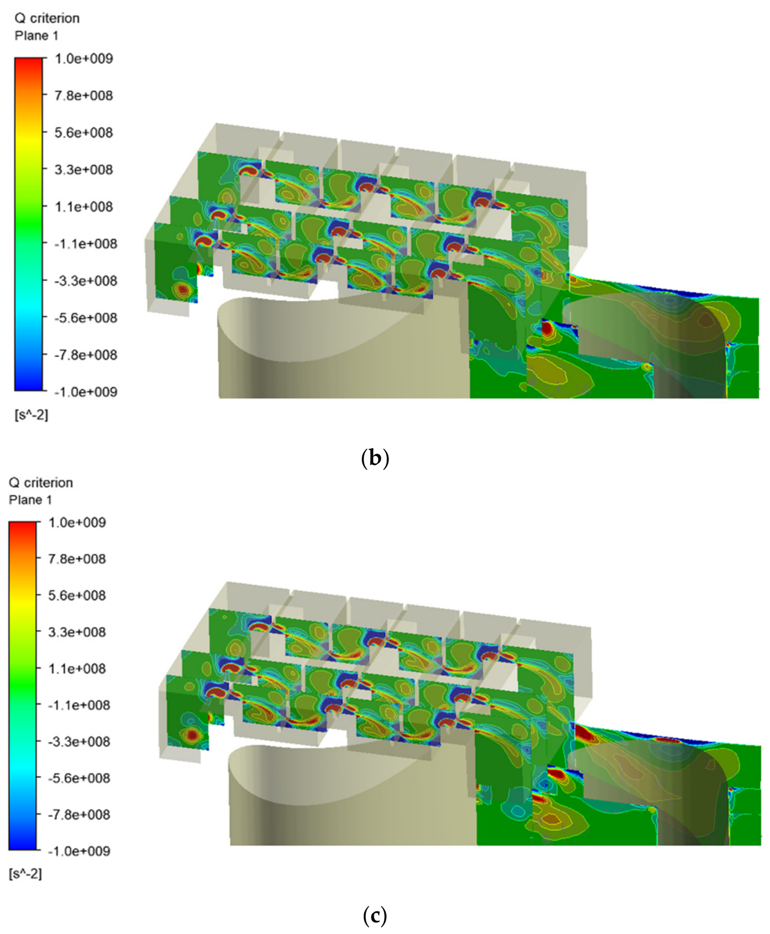
The Q-criterion is not a direct measure of vorticity strength, but it reflects the relative magnitude between the vorticity tensor and strain rate tensor, and it is applied to identify coherent vortex structures in the leakage-mainstream mixing region. To further analyze the detailed variation in vorticity during the mixing of the tip seal leakage flow with the mainstream flow, the axial vorticity is used to study the intensity and morphological changes in the vortices in the x-y plane. Thus, the significant changes in axial mixing flow are demonstrated. The axial vorticity is given as follows in Equation (4):
ω z   =   v x     u y
The mixing of blade tip seal leakage flow with the mainstream flow in the downstream stator blade passage is complex. The direction of the leakage vortices is related to the radial and tangential velocities of the steam. In order to observe the size and position changes in the tip leakage vortices, the axial vorticity given in Equation (4) is dimensionless. In addition, the counterclockwise direction is defined as positive vorticity, and the clockwise direction is defined as negative vorticity. The equation for dimensionless axial vorticity is as follows [11]:
ω a   =   v r x     v c y   ·   l v i n
where l is the height of the downstream stator blade, m. vin is the inlet velocity of the downstream stator blade, m/s. vr is the radial velocity of the downstream stator blade, m/s. vc is the tangential velocity of the downstream stator blade, m/s. x and y denote the local radial and tangential Cartesian coordinates, respectively.
The vorticity transport equation is used to analyze the formation and development process of the tip-seal leakage vortices. The equation is as follows [11]:
D ω z D t   =   ω   ·   V z     ω   ·   V z   +   ρ   ×   P ρ 2 z   +   V ( 2 ω ) z
where ω is the fluid vorticity, s−1. t is the time, s. ρ is the density, kg/m3.
The four terms on the right-hand side of Equation (6) represent the vortex stretching term, expansion term, baroclinic torque term, and viscous diffusion term, respectively. The vortex stretching term describes the effects of velocity gradients on vortex stretching, compression, and tilting. The expansion term represents the effect of fluid compressibility on vorticity. The baroclinic torque term is associated with the misalignment between pressure and density gradients, while the viscous diffusion term describes the diffusion of vorticity caused by viscous effects.
The corresponding expressions for the stretching, expansion, baroclinic torque, and viscous diffusion terms are given by Equations (7)–(10), respectively.
ω   ·   V z   =   ω x w x   +   ω y w y   +   ω z w z
ω   ·   V z   =   ω z u x   +   v y   +   w z
ρ   ×   P ρ 2 z   =   1 ρ 2 α v x P y     α v y P x
V ( 2 ω ) z   =   V 2 ω z x 2   +   2 ω z y 2   +   2 ω z z 2
where V is the fluid velocity, m/s. P is the fluid pressure, Pa.
In the present study, the axial vorticity and three vorticity-transport mechanisms, namely vortex stretching, expansion, and baroclinic torque, are analyzed to clarify the formation and evolution of tip-seal leakage vortices under different clearance conditions. The viscous diffusion term is comparatively small in the investigated flow field and is therefore not included in the subsequent quantitative analysis.
The local aerodynamic loss production rate is evaluated based on the viscous dissipation rate, which represents the irreversible loss associated with viscous effects and velocity gradients. The loss production rate per unit volume is expressed as:
ϕ   =   2 μ u i x j   +   u j x i 2     2 3 μ u i x i 2
where μ is the dynamic viscosity, Pa·s; ui and uj are the velocity components, m/s; and xi and xj are the corresponding spatial coordinates, m. The unit of ϕ is W/m3.
In the present study, the local viscous dissipation rate is used as an indicator of aerodynamic loss production to evaluate the local loss associated with viscous dissipation and enhanced velocity gradients resulting from the interaction between the tip-seal leakage flow and the rotor wake.

3. Results and Discussion

3.1. Flow Mixing Characteristics Based on Q-Criterion

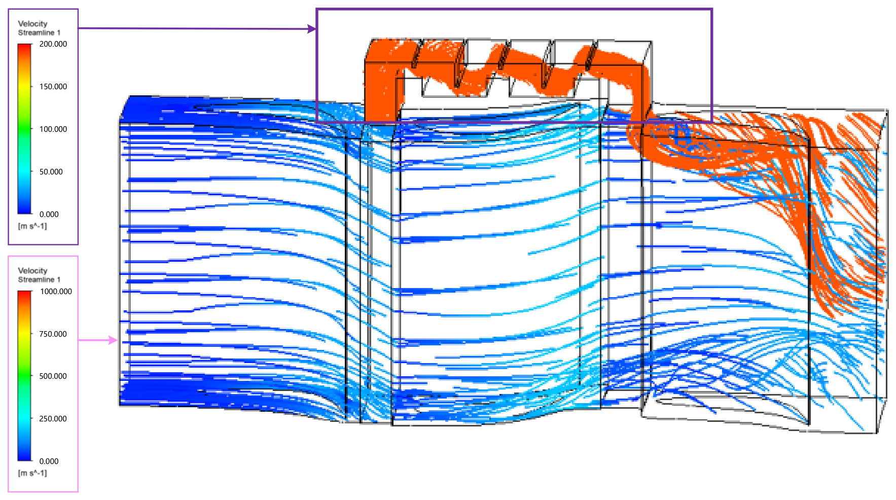
Figure 4 shows that the interaction between the tip seal leakage flow and the mainstream flow affects the flow field around the mid-span region of the downstream stator blades. Due to the leakage flow being pulled by the mainstream, this influence is mainly concentrated above 80% of the blade height. The Q-criterion is used to identify and visualize the coherent structures of the tip-seal leakage vortices and their spatial evolution during the mixing process. In this study, the evolution and spatial characteristics of the tip-seal leakage vortices are investigated under tip-seal clearances of 1.0, 1.5, and 1.9 mm. The vorticity transport equation is subsequently employed to quantify the contributions of the stretching, expansion, baroclinic torque, and viscous diffusion terms to vortex evolution.
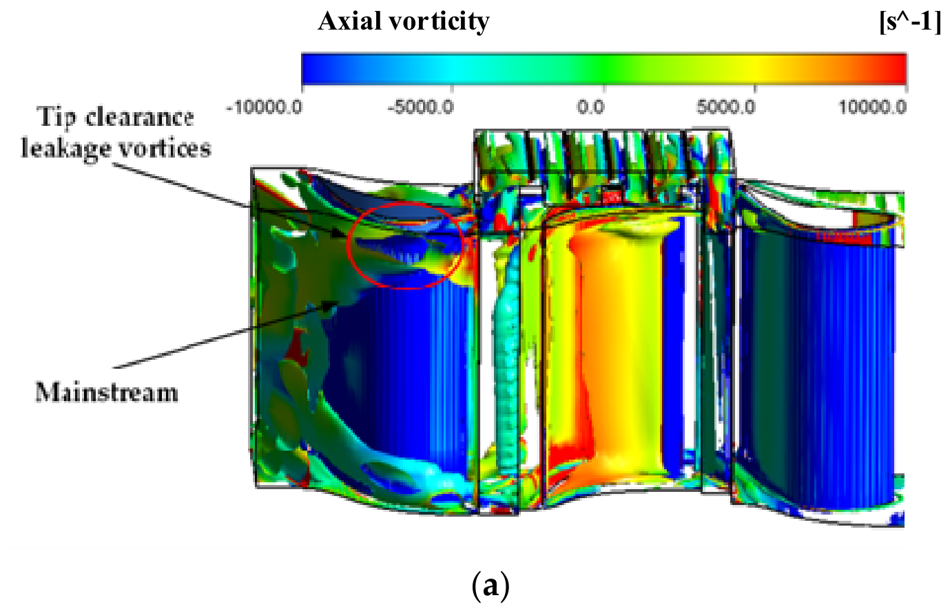
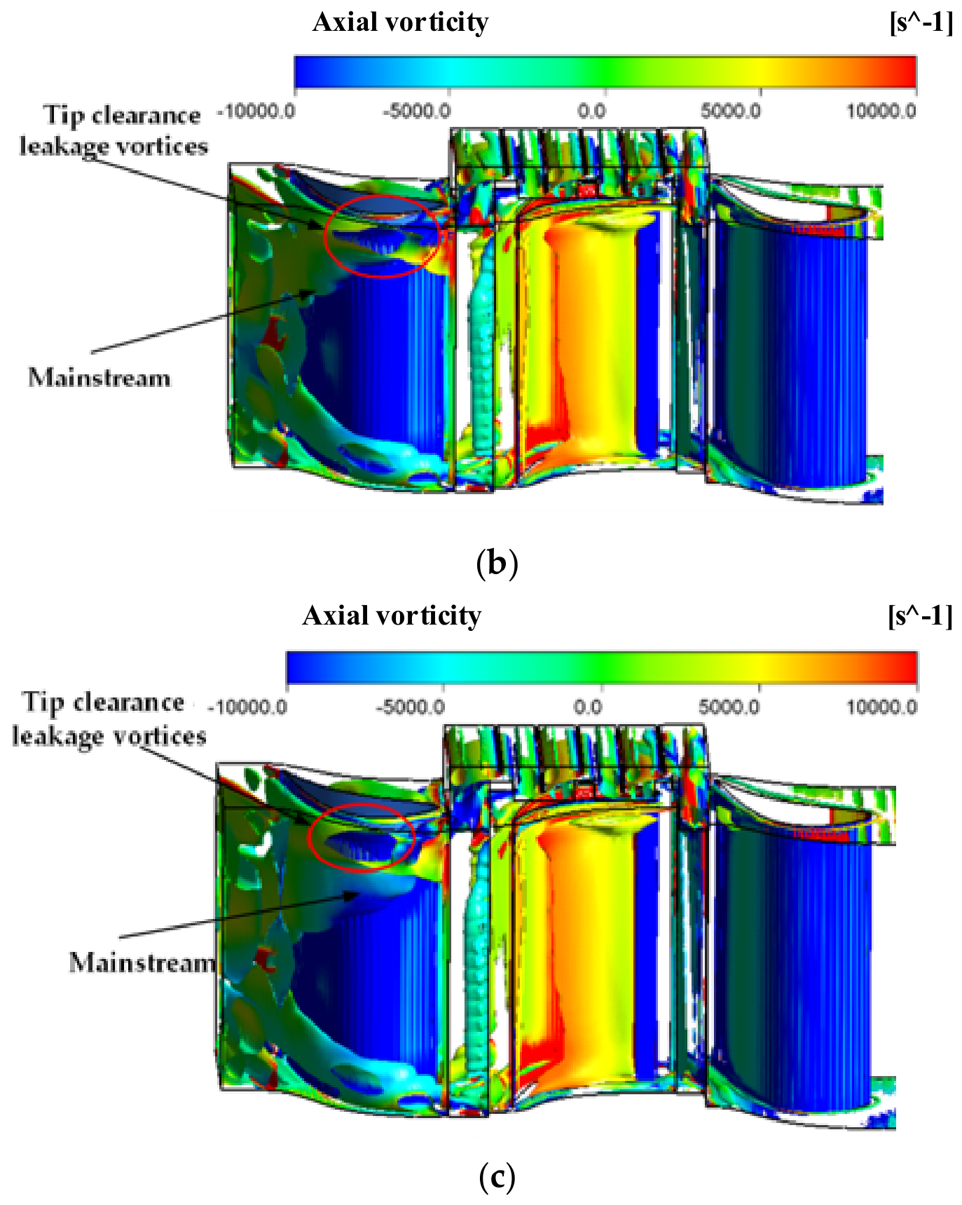
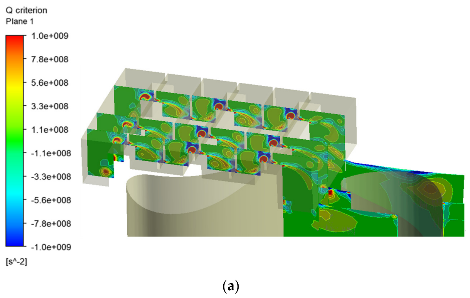
From Figure 5, it can be observed that the tip seal clearance leakage vortices mix and collide with the mainstream flow. Due to the pressure difference between the suction surface and the pressure surface of the stator blades, the tip seal leakage flow undergoes a flow reversal. Near the suction surface, the leakage flow adheres closely to it, while the portion moving away from the suction surface mixes with the mainstream flow and subsequently curls upward. As the tip seal clearance increases, the leakage flow intensifies, causing the flow on the suction surface to plunge further downward and enhancing the upward rolling tendency of the leakage flow away from the suction surface. This strengthens the interaction between the leakage flow and the mainstream, amplifying the upward flipping effect. The vortex intensity at the inlet of the tip seal cavity escalates with increasing clearance. At the downstream stator blades, the leakage vortices formed on the suction surface gradually intensify and migrate downstream, expanding the channel of the tip seal clearance leakage vortex. This compresses the mainstream, further intensifying the mixing with the leakage flow and broadening the influence range of the leakage flow. When the clearance is 1.0 mm, the leakage vortices do not roll upward as rapidly. This is attributed to the significant pressure difference between the pressure and suction surfaces, which accelerates the leakage flow compared to the 1.5 mm and 1.9 mm clearances. Consequently, the mixing channel between the leakage flow and the mainstream remains narrower, limiting the influence range.

3.2. Internal Vortex Evolution Inside the Tip Labyrinth Seal

In addition to affecting the flow field within the axial clearance between the rotor and stator, the tip leakage vortex under rotor–stator interaction also influences the flow field inside the tip seal cavity. The complex structure of the labyrinth tip seal leads to the formation of leakage vortices within the seal. As analyzed in Figure 5, the vortex quantities at the inlet and outlet of the tip seal change when the tip seal clearance varies. Therefore, investigating the formation and development of leakage vortices within the tip seal cavity is of significant importance for analyzing the intricate flow field of the tip labyrinth seal.
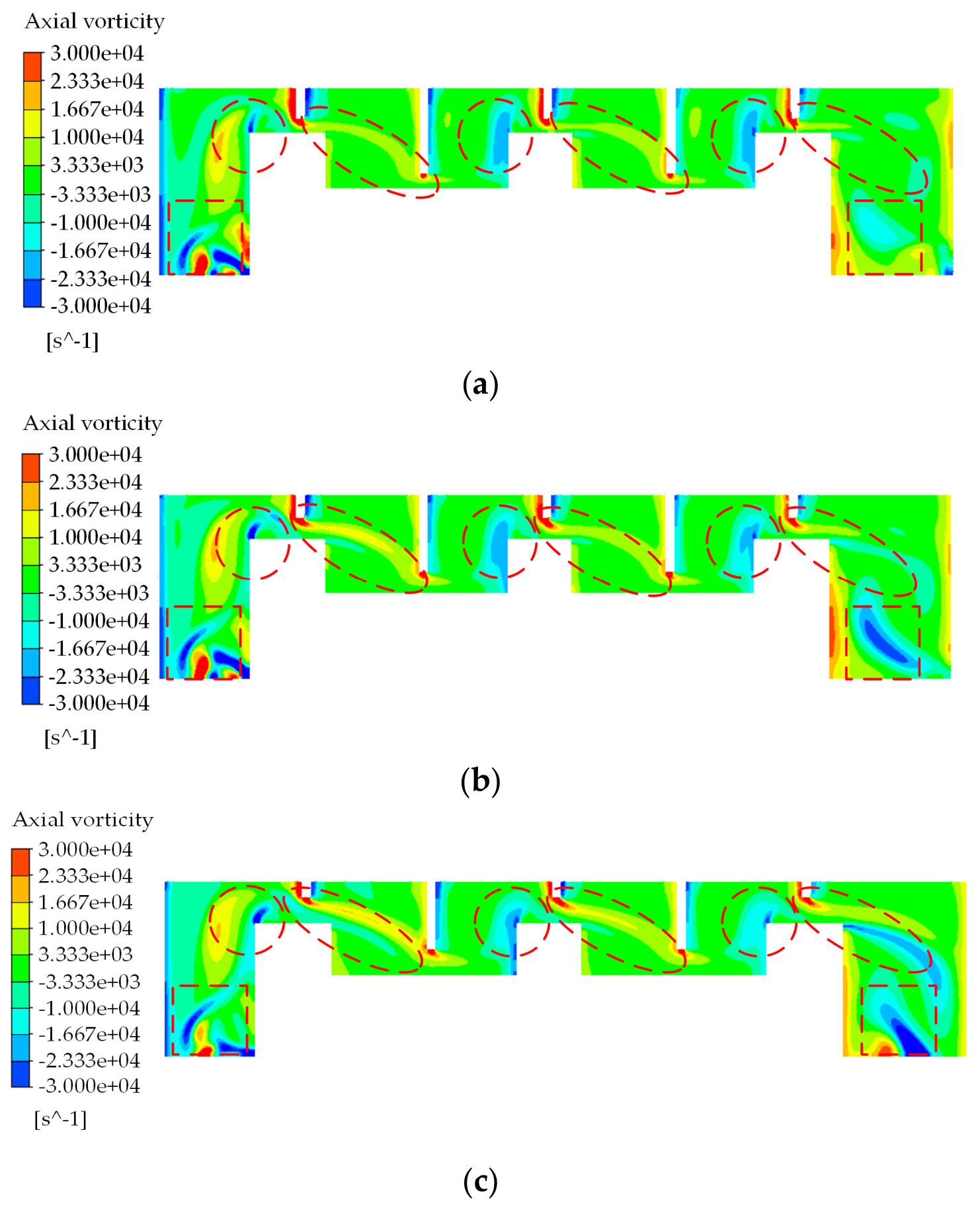
The formation and development patterns of tip seal clearance leakage vortices are analyzed by examining the variation in axial vorticity within the tip seal for different clearances. Figure 6 shows that as leakage flow passes through the tip seal, constriction and expansion acceleration at the seal teeth gradually lead to vortex formation within the seal. The vortices in the seal cavity are generated by the jet flow at the seal teeth, while the wake vortices form due to the suction effect. The strength of positive axial vorticity at the seal teeth increases with larger tip seal clearances. This behavior is associated with the increased leakage mass flow rate and enhanced interaction between the leakage flow and the surrounding flow as the clearance increases.
When the tip seal clearance rises, the leakage flow within the seal gap exhibits prominent inertial effects that stretch, distort and convection vortex structures. The mass flow rate of leakage at the seal inlet rises synchronously with clearance, amplifying impingement intensity on the seal boss and expanding the spatial coverage of negative vorticity near the inlet plane. With the enlargement of tip clearance, the zone occupied by negative vorticity extends both at the seal outlet and downstream of the final seal tooth. Larger leakage mass flow yields stronger inertial action, and the high-speed jet at the seal outlet produces stronger local flow impingement on the outlet wall.
For the tested minimum clearance of 1.0 mm, the magnitude of positive and negative vorticity within the seal outlet region remains close to zero. When clearance expands from 1.0 mm to the maximum design value of 1.9 mm, the spatial scale and peak absolute value of both positive and negative vortex structures grow markedly. This quantitative comparison indicates that smaller tip clearances suppress vortex generation and reduce the total leakage mass flow through the labyrinth seal.
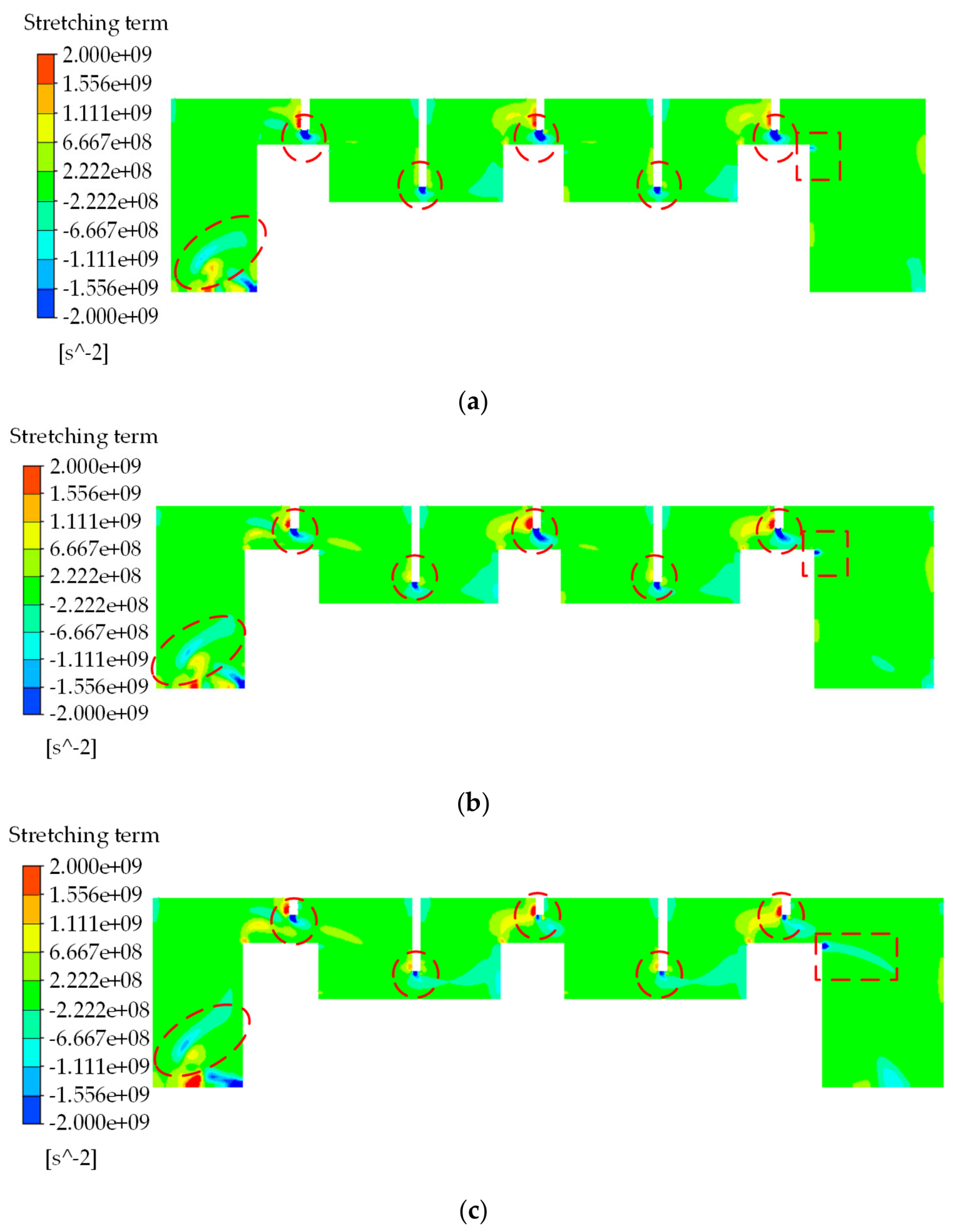
The formation of tip seal leakage vortices, as described by Equation (6), involves stretching, expansion, and baroclinic torque terms. These terms have different effects, leading to variations in the formation patterns of the vortices. Therefore, the contributions of these three terms under different tip seal clearances are quantitatively analyzed. From Figure 7, it is evident that as the tip seal clearance increases, the negative stretching effect of the seal teeth gradually weakens. As the leakage flow increases, the impact and jet intensities strengthen behind the boss-corner regions at the seal inlet and outlet. The positive vortex at the seal inlet and the negative vortex at the seal outlet are enhanced. These vortices undergo gradual stretching, deformation, and even fragmentation. So, the vortices at the seal inlet and outlet exhibit complex structures.
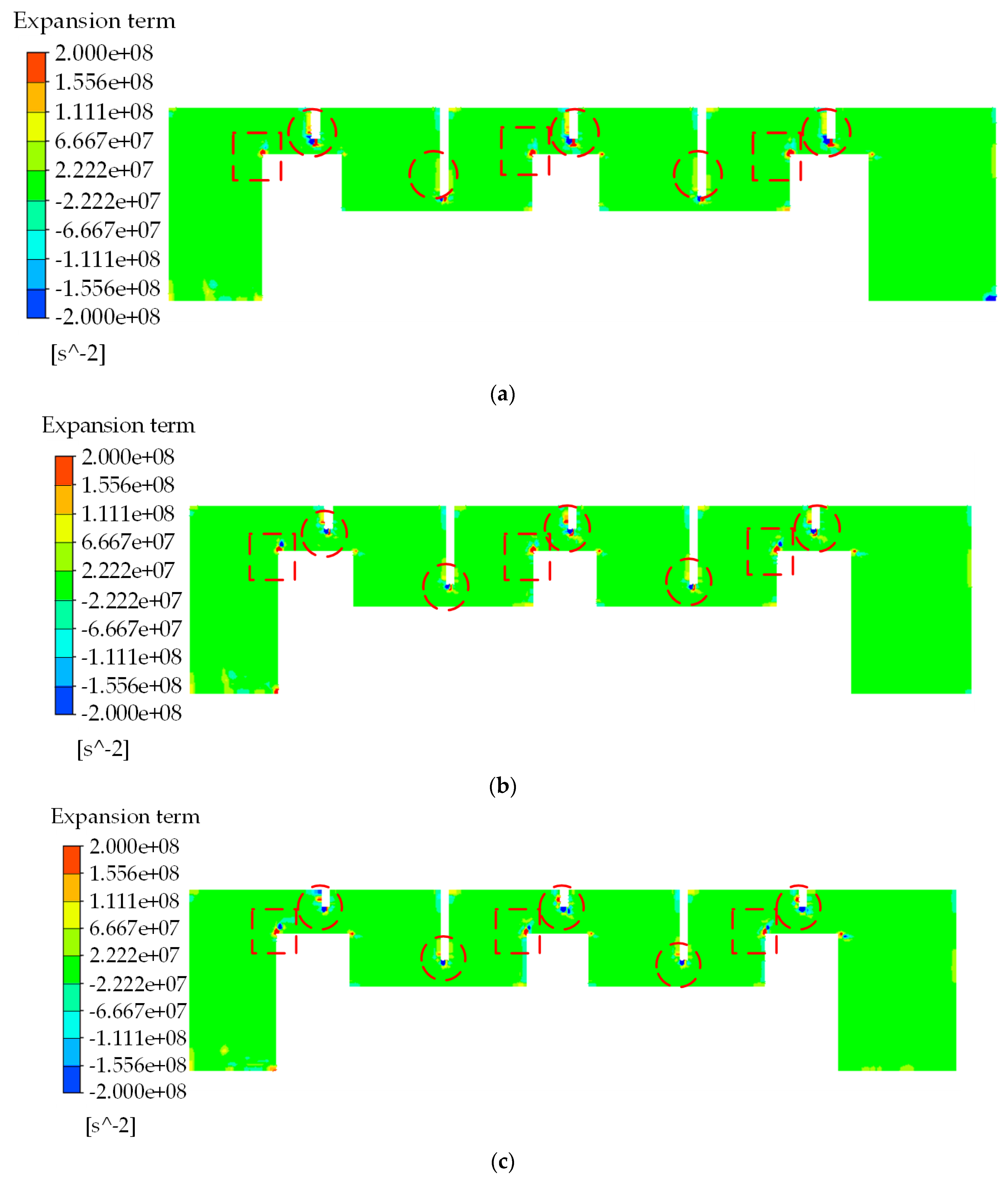
From Figure 8, it can be observed that as the tip seal clearance increases, the expansion term at the seal teeth changes from positive to negative. This indicates that the local vorticity at the seal teeth decreases, while the expansion effect gradually strengthens. It also suggests that the expansion term has a relatively stronger influence on the local vorticity variation near the seal teeth under the investigated conditions. The expansion effect at the leading edge of the seal teeth increases with the enlargement of the tip seal clearance. The expansion effect at the seal inlet and outlet is not significant, indicating that the stretching term plays a more prominent role in the vorticity at these locations.
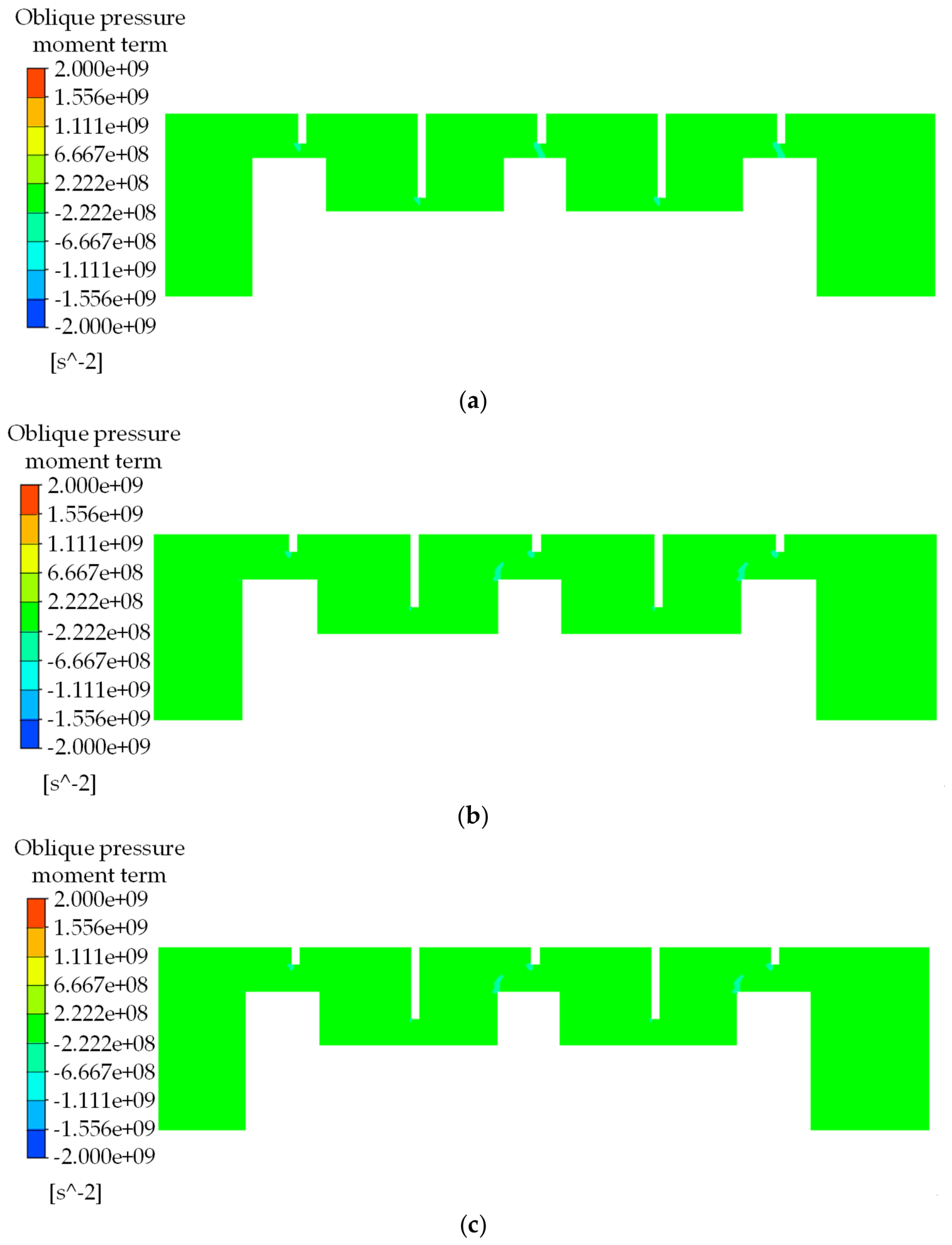
From Figure 9, it can be observed that the baroclinic torque term exhibits relatively weak variation compared with the stretching and expansion terms under different tip-seal clearances. Although local changes can be observed near the leading edges of the seal teeth, the overall magnitude of this term remains relatively small. Therefore, the baroclinic torque term exhibits a relatively weaker contribution under the investigated operating conditions and is not considered in the subsequent comparative analysis.
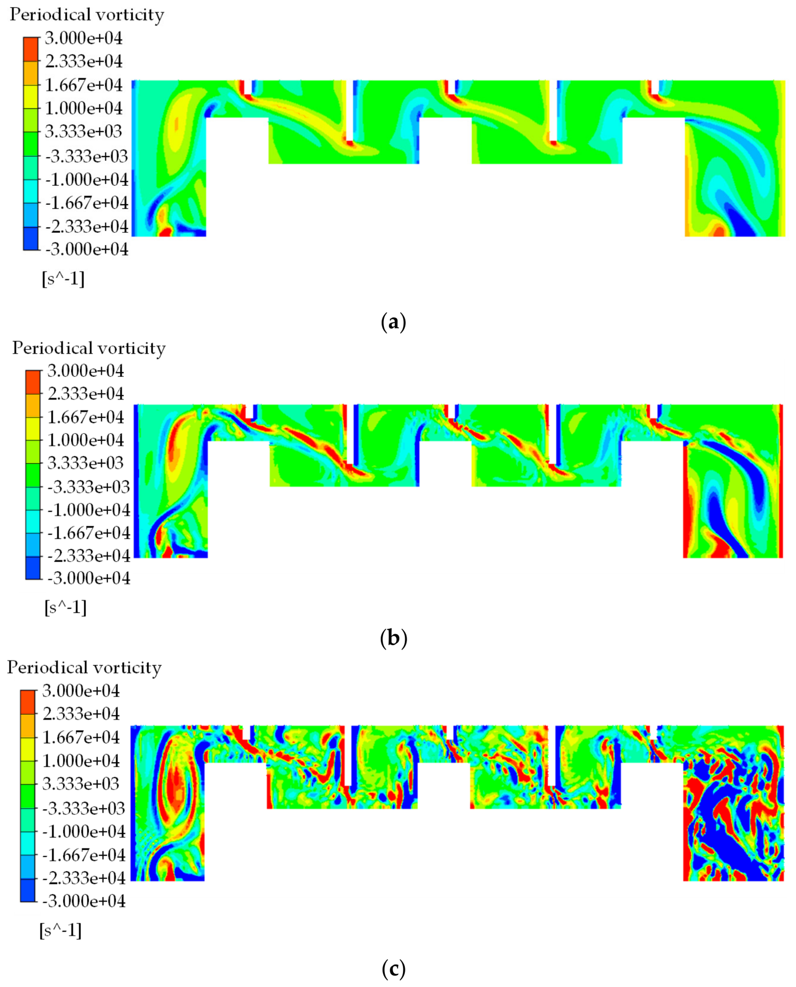
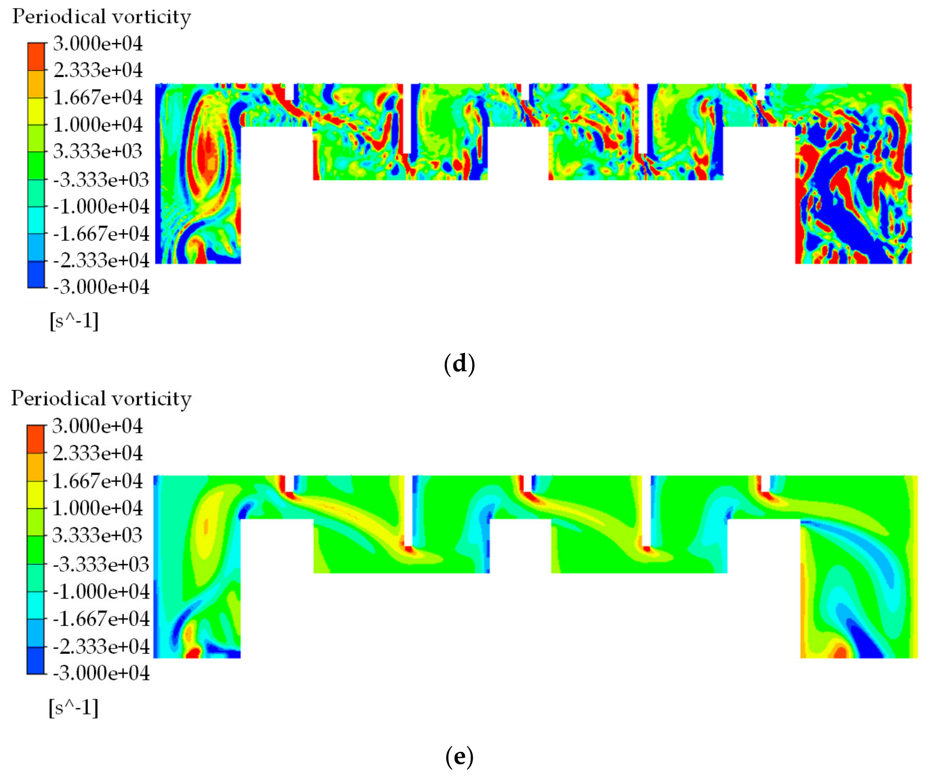
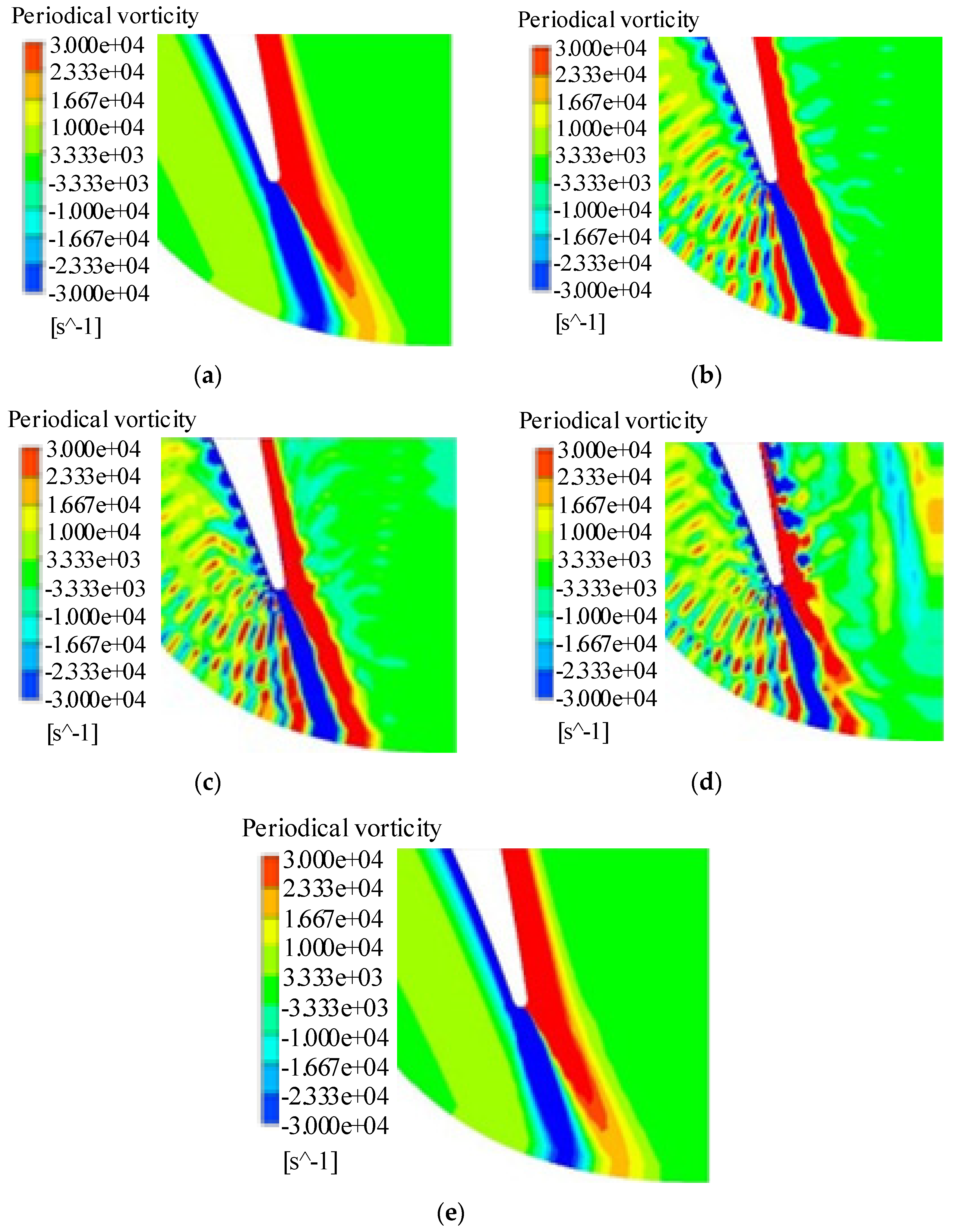
Here, T denotes the blade-passing period, i.e., the time required for one rotor blade to pass through one stator passage, corresponding to approximately 29 sub-time steps. The unsteady calculation was performed for two blade-passing periods, and the second period was used for subsequent analysis. As shown in Figure 10, the vorticity field exhibits a periodic evolution over one complete blade-passing period, with the tip-leakage vortex undergoing a repeatable sequence of formation, development, and convection.
It can be observed that at 1/4T, the negative vorticity at the tip seal inlet gradually stretches and wraps around the positive vorticity. At 2/4T, it merges with the negative vorticity at the first boss corner. At 3/4T, the upper positive vorticity squeezes and truncates the negative vorticity, resulting in the disruption of the tip seal inlet vortex system. By 4/4T, the tip seal inlet vortex returns to a configuration similar to the initial state. The complexity of the tip seal inlet vortex system with time is due to the significant role played by the stretching term in the formation of the inlet vortices. The stretching, compressing, and tilting effects of the stretching term cause the negative vortices at the tip seal inlet to stretch and envelop the positive vortices, gradually expanding their range and increasing their intensity through the enhanced interaction. The positive vorticity at the seal teeth evolves downstream over time, interacting with the negative vorticity within the seal cavity. This interaction is primarily due to the combined effects of the stretching and expansion terms, which stretch, compress, and tilt the vortices. However, the formation and evolution of vorticity within the seal cavity are closely associated with the stretching effect, which contributes significantly to the deformation and transport of leakage vortices. At 1/4T, the negative vortices behind the boss corner and at the outlet gradually expand. At 2/4T, the negative vortices mix with positive vorticity and eventually break apart. At 3/4T, the small vortex system formed at the boss corner of the sealing outlet mixes with other vortices gradually, resulting in the appearance of numerous small-scale vortices at the sealing outlet. This behavior is attributed to the combined effects of jet inertia and the stretching term on the vortices formed at the boss corner and seal outlet, thereby expanding the influence range of vorticity and intensifying the interaction between the leakage flow and the mainstream flow.

3.3. Aerodynamic Performance of Rotor Blades Influenced by Mixing Flow

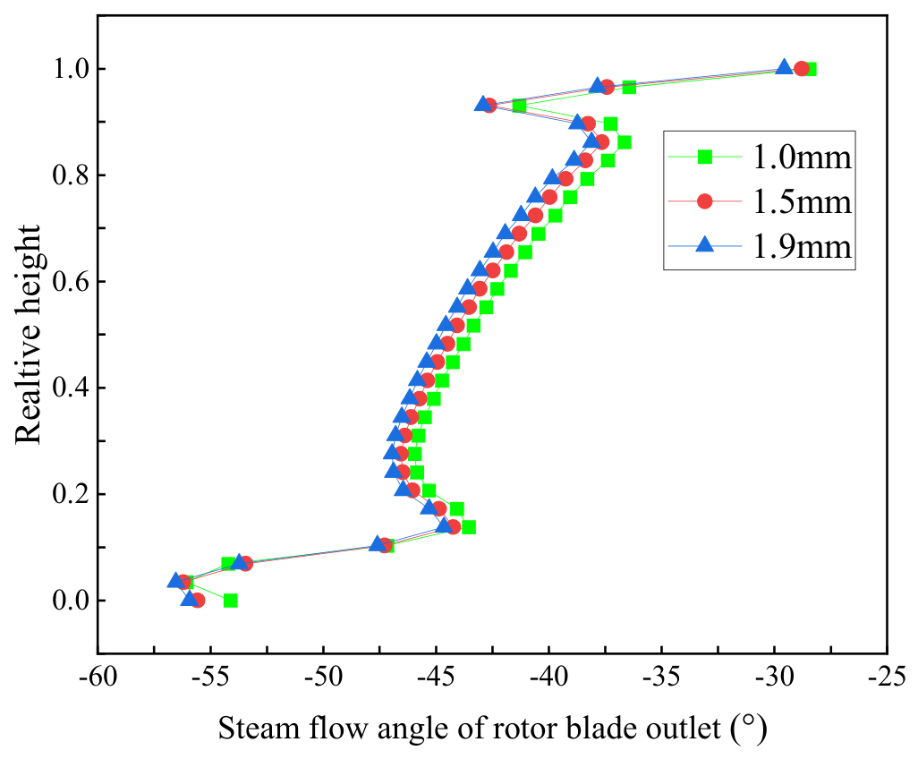
The mixing of the leakage flow with the mainstream flow at the outlet of the labyrinth seal leads to changes in the outlet pressure of the rotor blades. This has an influence on the aerodynamic performance of the rotor blades. From Figure 11, it can be seen that the flow angle deviation begins to occur at 85% of the blade height and increases with the increase in tip seal clearance. This is a result of the enlarged tip seal clearance leakage vortex channel due to the increased clearance, which enhances the interaction with the upstream channel vortex. This interaction causes a change in the direction of rotation of the vortex, leading to a larger deviation in the flow angle at the outlet of the rotor blades, resulting in a flow-angle shift from the mid-span region toward the endwall within the 20–70% span range. There is a noticeable deviation in the flow angle at 10% of the blade height, indicating that the downstream vortices at the blade root also influence the distribution of the flow angle at the outlet of the rotor blades.
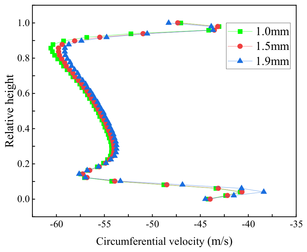
From Figure 12, it can be seen that the leakage flow has a significant impact on the circumferential velocity of the rotor blades above 85% of the blade height. The circumferential velocity decreases in the mid-span region with the increase in tip seal clearance. This is because the mixing of tip seal leakage flow with the mainstream flow reduces rotor interference and the negative incidence, resulting in an increased tip seal leakage flow, an enlarged flow angle at the outlet of the rotor blades, and a decreased circumferential velocity at the outlet. The variation in circumferential velocity above 85% of the blade height is more pronounced than that in the mid-span region. This is primarily due to the variations in the velocity gradients induced by the rotor blade wake.
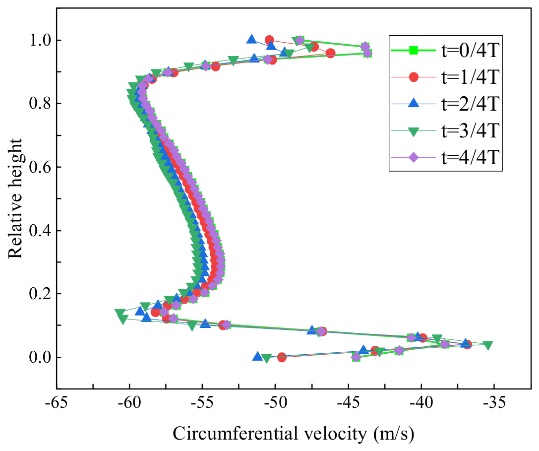
From Figure 13, it can be observed that the circumferential velocity varies at different time steps at the outlet of the rotor blades. The variation is more pronounced at the blade root, while the circumferential velocity at the blade tip exhibits temporal fluctuations. This is attributed to the increased tip seal leakage flow, which strengthens the inertial jet effect of the leakage flow, enhances the mixing with the mainstream flow, and leads to changes in the flow angle at the outlet of the rotor blades. As a result, the circumferential velocity exhibits pronounced temporal variations above 85% of the blade height at the outlet of the rotor blades.
Figure 14 represents the periodic vorticity cloud at the trailing edge of the rotor blades. At 0/4T, two positive and negative vortices appear at the trailing edge of the rotor blades, gradually developing downstream. At 1/4T, the trailing edge separation vortices begin to shed at the pressure surface of the rotor blades. By 3/4T, the separation vortices shedding from the suction surface of the rotor blades mix with the negative tip seal leakage vortices, causing the separation and shedding of the positive vortices at the trailing edge. This phenomenon has an impact on the aerodynamic performance of the rotor blades. At 4/4T, the vorticity at the trailing edge gradually returns to its initial configuration, forming a periodic variation.
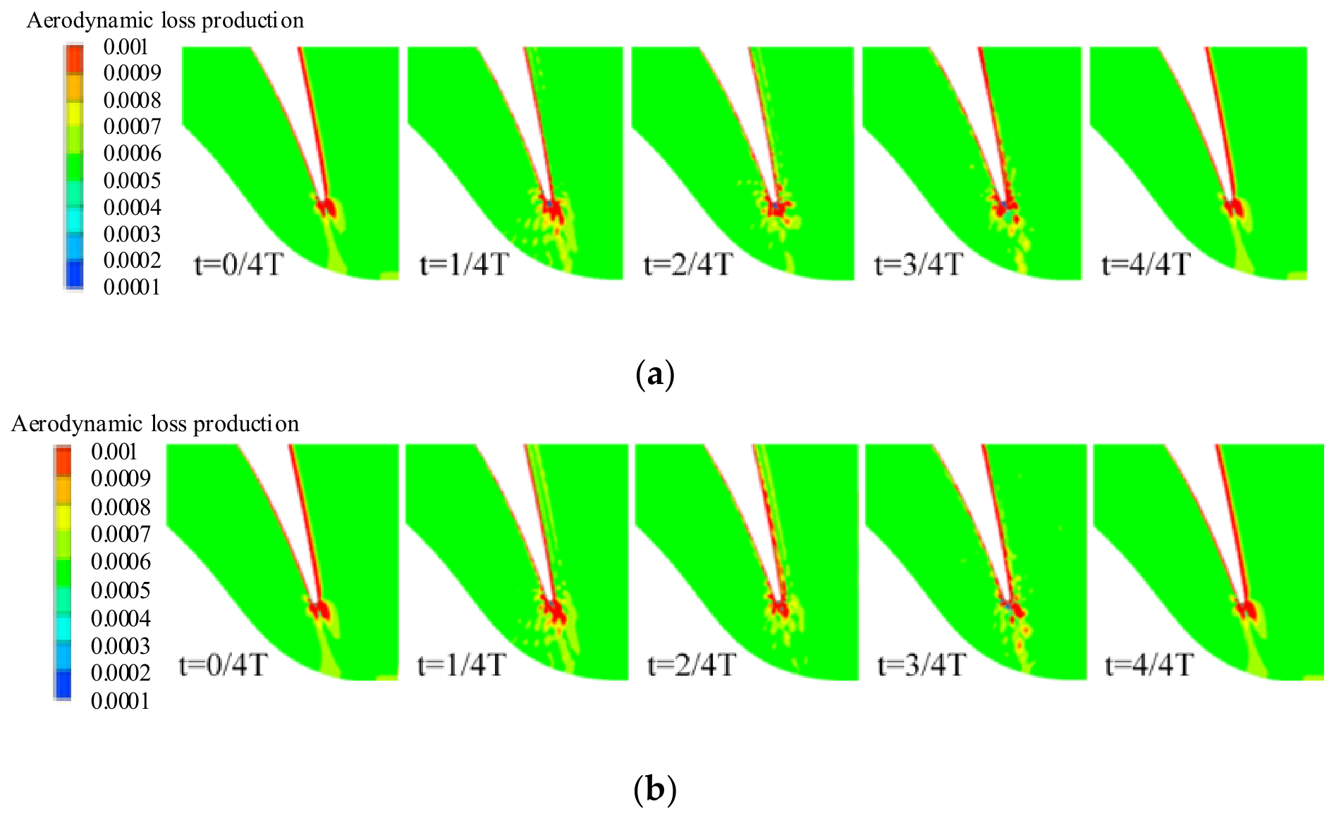
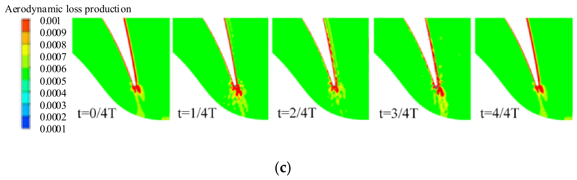
From Figure 15, it is evident that the suction surface boundary layer of the rotor blades exhibits a significant velocity gradient. According to the aerodynamic loss production rate Equation (11), a high-loss region forms in the boundary layer of the rotor blades, contributing to aerodynamic losses. As trailing-edge vortices shed, this high-loss region progressively migrates downstream, causing significant aerodynamic losses at the blade’s trailing edge. Over time, aerodynamic losses exhibit periodic variations: at 1/4T, trailing-edge vortex shedding induces a loss increase; by 2/4T, losses diminish gradually while migrating downstream with vortex shedding; at 3/4T, loss productivity rises again due to separation vortices on the suction surface breaking into smaller-scale vortices that interact with leakage vortices, intensifying leakage flow velocity gradients and elevating loss productivity. As the mixing between these vortices weakens, loss productivity declines and continues downstream migration, resulting in a high–low–high–low periodic pattern of trailing-edge losses. Larger tip seal clearance further amplifies loss productivity by increasing leakage flow, which enhances mainstream flow mixing and velocity gradients, ultimately elevating aerodynamic losses. As time evolves, the unsteady effects enhance the mixing between the shedding vortices and the leakage vortices at the rotor blade’s trailing edge, leading to an increase in the aerodynamic loss production rate as well.

3.4. Aerodynamic Performance of Stator Blades Influenced by Mixing Flow

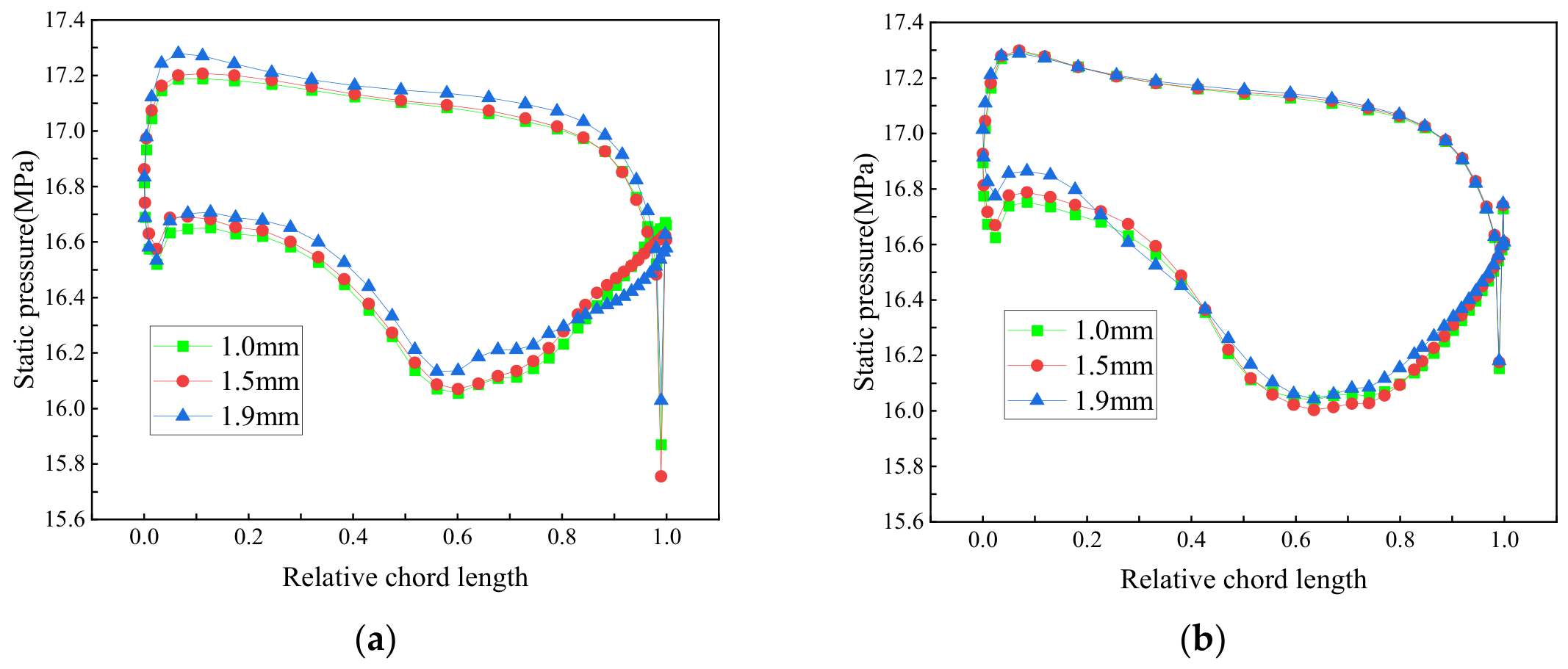
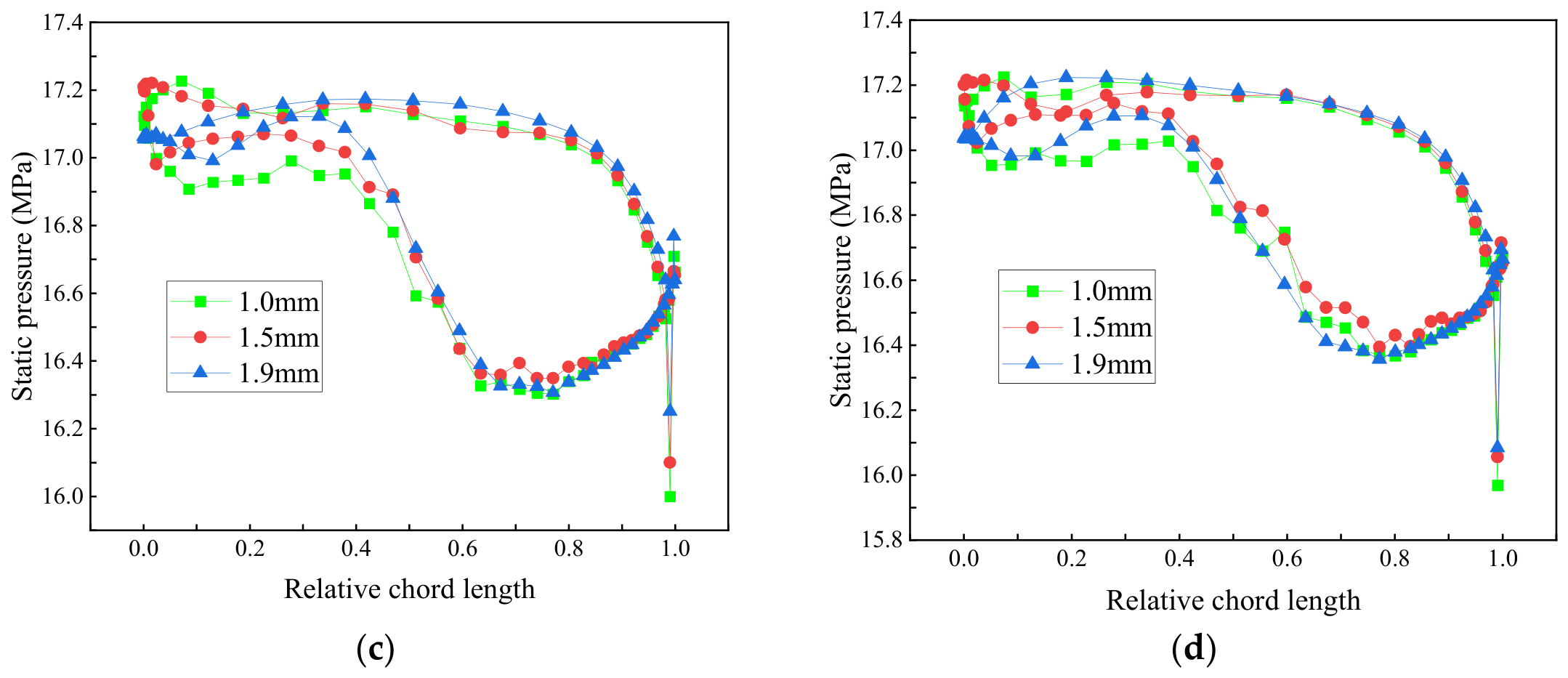
As shown in Figure 16, increasing the tip seal clearance modifies the static-pressure distribution on the downstream stator blade surface, with the most pronounced differences occurring on the suction surface in the upper-span region. At 80% blade height, noticeable differences in static pressure among the three clearance conditions are observed near the leading edge of the suction surface, as shown in Figure 16b. These differences are associated with the enhanced interaction between the leakage flow and the mainstream on the suction side as the tip seal clearance increases. The static-pressure distributions on the pressure surface are relatively less sensitive to the tip seal clearance, whereas more pronounced variations are observed on the suction surface. In particular, at 95% and 99% blade heights, pronounced differences in the suction-surface static-pressure distributions occur within the forward 80% of the chord length of the stator blade. This behavior is attributed to the pressure difference between the pressure and suction surfaces, which drives the tip-seal leakage flow toward and along the suction surface. As the tip seal clearance increases, the leakage flow becomes stronger, and its interaction with the mainstream is enhanced, thereby enlarging the region affected by the leakage flow and modifying the static-pressure distribution on the stator blade surface. The relatively small differences observed on the pressure surface in the upper-span region are mainly associated with the wake of the upstream rotor blades.
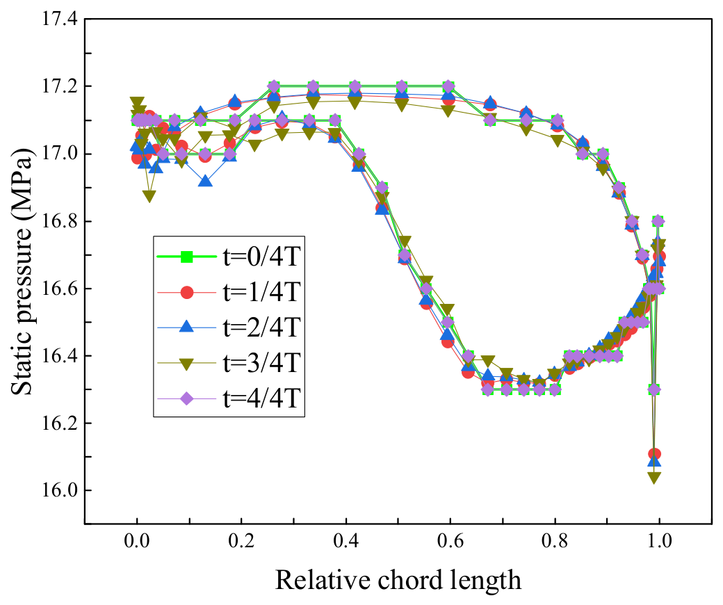
From Figure 17, it can be observed that at different time steps, the pressure on the surface of the downstream stator blades varies. The pressure fluctuations are particularly evident at the leading edge of the stator blades. There are significant pressure fluctuations on the suction surface within the forward 40% of the chord length of the stator blade. These fluctuations are caused by the mutual mixing of the leakage flow and the mainstream flow. At approximately 90% of the chord length on the pressure surface, there are noticeable pressure fluctuations, which are also influenced by the wake from the upstream rotor blades.
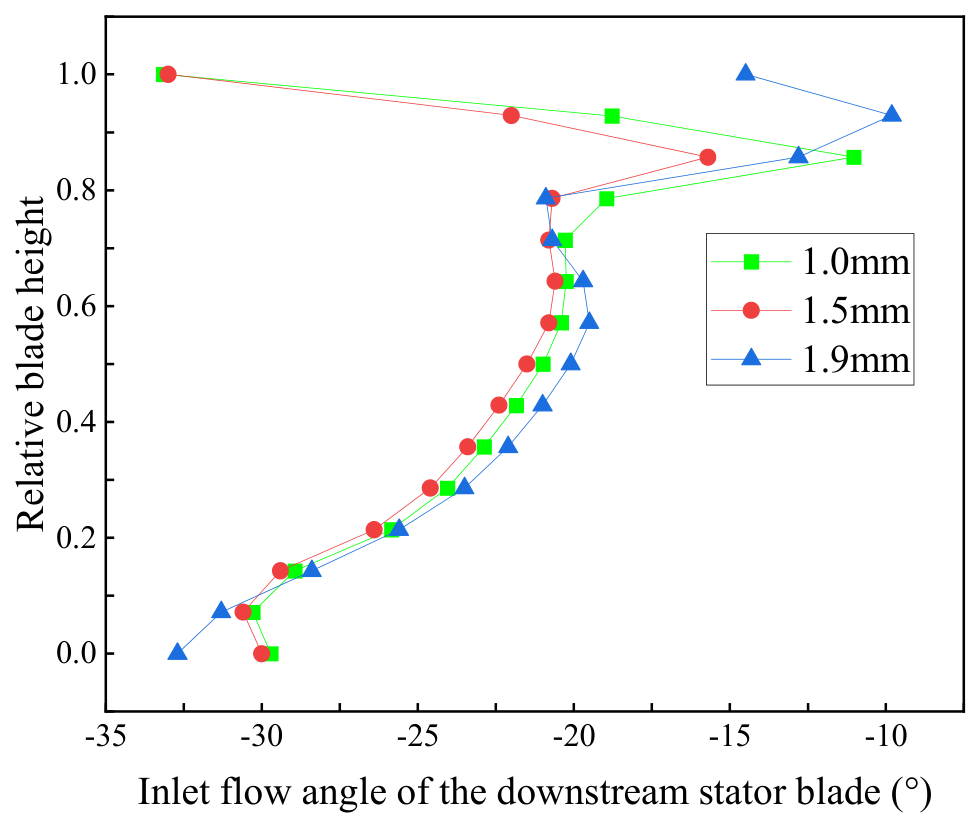
From Figure 18, it can be observed that the mutual mixing of the tip seal clearance leakage flow and the mainstream flow becomes stronger with the tip seal clearance increasing. This results in significant flow-angle variations in the downstream stator above 80% of the blade height. With the tip seal clearance increasing, the downward impact area of the tip seal clearance leakage flow expands, squeezing the normal flow within the passage. This leads to an underturning from mid-span to the end wall within the range of 20–70% of the blade height, which is caused by the displacement of the upstream passage vortex by the tip seal clearance leakage vortex, resulting in a shift in the flow angle. Additionally, significant changes in the flow angle can be seen at 10% of the blade height, indicating that the downstream vortices at the blade root also influence the distribution of the flow angle at the inlet of the downstream stator blades.
From Figure 19, it can be observed that there is a distinct distribution of positive and negative vortices at the inlet and outlet of the tip seal. With the increase in tip seal clearance, the strength of these vortices gradually increases. At the outlet of the tip seal, the positive vortices compress the negative vortices on the pressure surface of the stator blades, resulting in significant pressure fluctuations on the downstream pressure surface. On the suction surface, the tip seal clearance leakage vortices expand their influence range and enhance the mixing interaction with the negative vortices. This leads to obvious pressure fluctuations and significant aerodynamic losses on the suction surface of the stator blades.
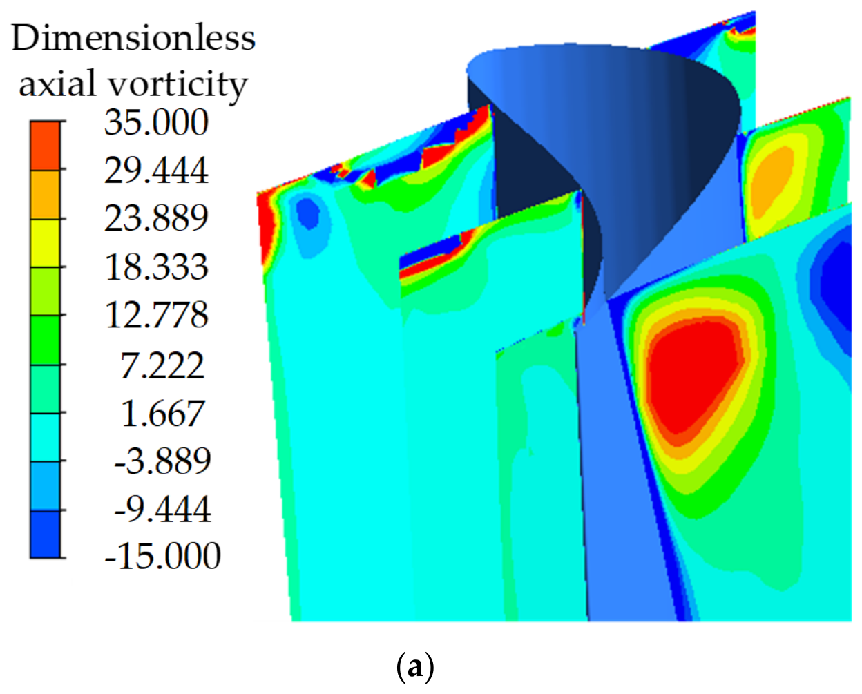
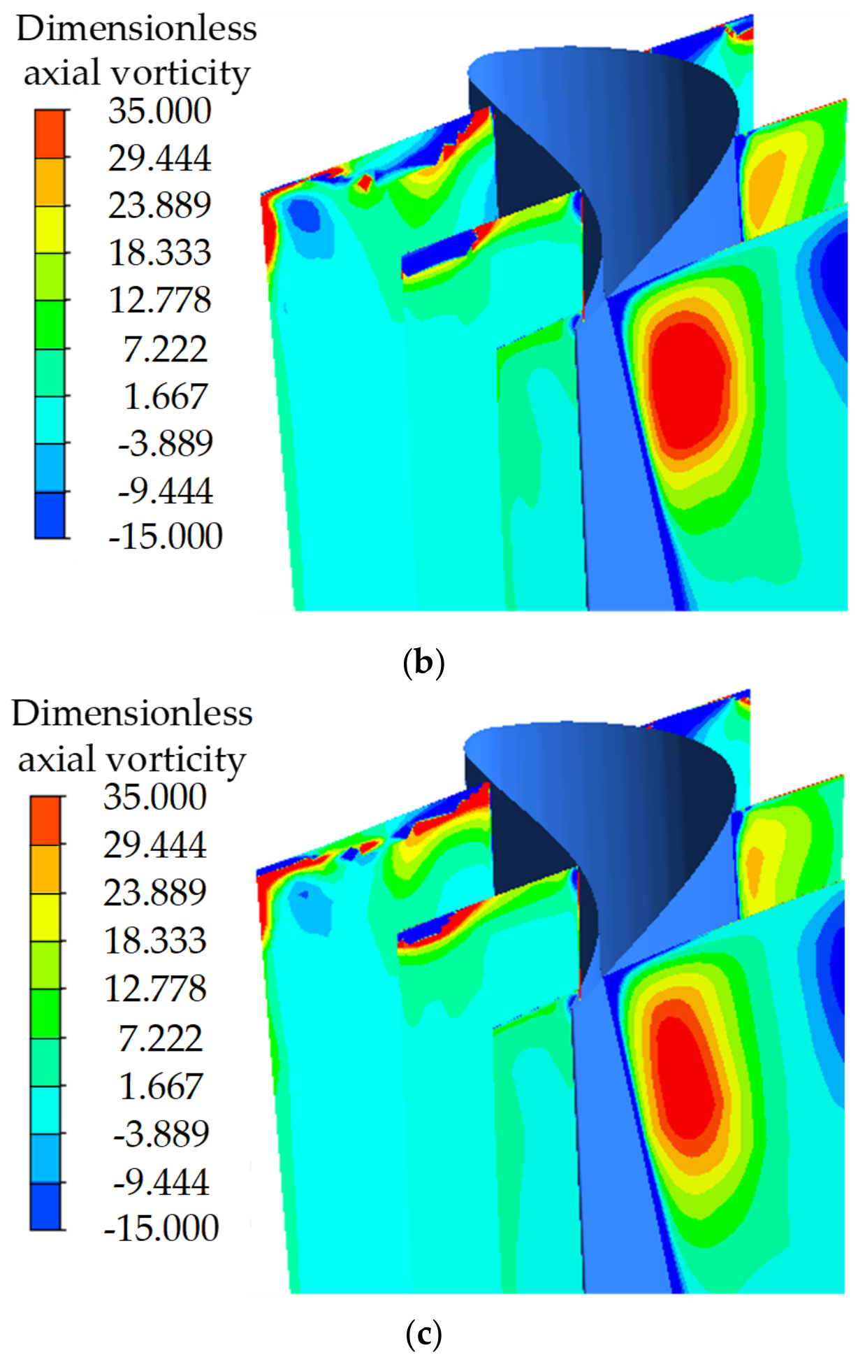
From Figure 20, as tip seal clearance rises, radial scale and coverage of leakage vortices expand gradually. Negative and positive vortices interact at the leading edge of the blade pressure side, which originates from upstream rotor wake shedding propagating downstream and complicates the vortex distribution near the stator leading edges.

4. Conclusions

In this study, a model of a 1.5-stage blade in the high-pressure cylinder of a 1000 MW ultra-supercritical steam turbine is established. The effects of the mixing between the tip seal leakage flow and the mainstream flow on the aerodynamic performance of the rotor and stator blades are analyzed through unsteady calculations. The specific conclusions are as follows:
(1)
Enlarged tip seal clearance strengthens the squeezing action of leakage vortices on the mainstream flow, which amplifies flow mixing and extends its affected zone. The Q-criterion is capable of capturing tip leakage vortices and characterizing their suction, over-turning and migration features in the mixing zone.
(2)
The expansion term exhibits a relatively stronger effect on local vorticity variation around the seal teeth and front boss corners, whereas the vortex stretching term plays an important role in the formation and evolution of leakage vortices at the seal inlet, outlet, inner cavity, and rear boss corners. The baroclinic torque term exhibits a relatively weaker contribution under the investigated conditions and is therefore not considered in the subsequent analysis.
(3)
The interaction between leakage and mainstream flow reverses vortex rotation at the rotor outlet, producing prominent flow angle deviation over the upper 85% span. As tip clearance rises, aerodynamic loss production grows and propagates downstream along shed wake vortices, accompanied by pronounced circumferential velocity non-uniformity above 85% blade height.
(4)
Increasing the tip seal clearance intensifies the influence of leakage vortices on the downstream stator. Pronounced flow-angle variations occur above 80% of the blade height, while the most severe flow-angle distortion is observed near the blade tip, particularly above 95% span. Meanwhile, the static-pressure distributions on the downstream stator suction surface are significantly affected in the upper-span region, especially at 95% and 99% blade heights.

Author Contributions

Conceptualization, D.L. and L.W.; Methodology, D.L., H.S. and Z.Z.; Software, D.L.; Validation, D.L. and L.W.; Formal analysis, L.W.; Investigation, L.C.; Resources, H.S. and Z.Z.; Data curation, L.C.; Writing—original draft, L.W.; Writing—review and editing, D.L.; Visualization, D.L.; Supervision, Z.Z.; Project administration, L.C.; Funding acquisition, L.C. All authors have read and agreed to the published version of the manuscript.

Funding

This research was funded by the National Science Foundation of China, grant number 52176003.

Data Availability Statement

The raw data supporting the conclusions of this article will be made available by the authors on request.

Acknowledgments

This work was supported by the National Science Foundation of China (No. 52176003), which is gratefully acknowledged.

Conflicts of Interest

The authors declare no conflicts of interest.

Nomenclature

The following nomenclature and symbols are used in this manuscript.
VariableDefinition
ηTurbine isentropic efficiency
Tt,inInlet total temperature of the stage [K]
Tt,outOutlet total temperature of the stage [K]
Pt,inInlet total pressure of the stage [Pa]
Pt,outOutlet total pressure of the stage [Pa]
γAdiabatic index for superheated steam
PtArea-averaged total pressure inside the flow field [Pa]
CptTotal pressure loss coefficient
uThe component of the velocity vector in the x direction [m/s]
vThe component of the velocity vector in the y direction [m/s]
wThe component of the velocity vector in the z direction [m/s]
xx direction
yy direction
zz direction
ωzAxial vorticity [s−1]
lHeight of the downstream stator blade [m]
vmInlet velocity of the downstream stator blade [m/s]
vrRadial velocity of the downstream stator blade [m/s]
vcTangential velocity of the downstream stator blade [m/s]
ωaDimensionless axial vorticity
tTime [s]
ρFluid Density [kg/m3]
VFluid velocity [m/s]
ωFluid vorticity [s−1]
ωxThe vorticity in the y-z direction [s−1]
ωyThe vorticity in the x-z direction [s−1]
PFluid pressure [Pa]
ϕAerodynamic loss production rate
μFluid viscosity [Pa·s]

References

  1. Sjolander, S.A.; Amrud, K.K. Effects of tip clearance on blade loading in a planar cascade of turbine blades. J. Turbomach. 1987, 109, 237–244. [Google Scholar] [CrossRef] [Scilit]
  2. You, D.H.; Wang, M.; Moin, P.; Mittal, R. Effects of tip-gap size on the tip-leakage flow in a turbomachinery cascade. Phys. Fluids 2006, 18, 105102. [Google Scholar] [CrossRef] [Scilit]
  3. Yamamoto, A. Endwall flow/loss mechanisms in a linear turbine cascade with blade tip seal clearance. J. Turbomach. 1989, 111, 264–275. [Google Scholar] [CrossRef] [Scilit]
  4. Gao, J.; Zheng, Q. Comparative investigation of unsteady flow interactions in endwall regions of shrouded and unshrouded turbines. Comput. Fluids 2014, 105, 204–217. [Google Scholar] [CrossRef] [Scilit]
  5. Behr, T. Control of Rotor Tip Leakage and Secondary Flow by Casing Air Injection in Unshrouded Axial Turbines. Ph.D. Thesis, ETH Zürich, Zürich, Switzerland, 2007. [Google Scholar]
  6. Cao, C.; Chew, J.W.; Millington, P.R.; Hogg, S.I. Interaction of rim seal and annulus flows in an axial flow turbine. J. Eng. Gas Turbines Power 2004, 126, 786–793. [Google Scholar] [CrossRef] [Scilit]
  7. Pogorelov, A.; Meinke, M.; Schröder, W. Cut-cell method based large-eddy simulation of tip-leakage flow. Phys. Fluids 2015, 27, 075102. [Google Scholar] [CrossRef] [Scilit]
  8. Kim, J.H.; Ahn, J. Large eddy simulation of leakage flow in a stepped labyrinth seal. Processes 2021, 9, 2179. [Google Scholar] [CrossRef] [Scilit]
  9. Yang, Y.; Ma, H.W.; Zhong, Y.F.; Zhang, Q.D. Modal analysis and vortex trajectory description for tip leakage flow of a transonic turbine cascade. J. Therm. Sci. 2023, 32, 789–801. [Google Scholar] [CrossRef] [Scilit]
  10. Zhou, K.; Zhou, C. Unsteady effects of vortex interaction on tip leakage vortex breakdown and its loss mechanism. Aerosp. Sci. Technol. 2018, 82–83, 363–371. [Google Scholar] [CrossRef] [Scilit]
  11. Xu, M.; Cheng, H.; Ji, B.; Peng, X. LES of tip-leakage cavitating flow with special emphasis on different tip clearance sizes by a new Euler-Lagrangian cavitation model. Ocean Eng. 2020, 213, 107661. [Google Scholar] [CrossRef] [Scilit]
  12. Rusch, D.; Pfau, A.; Schlienger, J.; Kalfas, A.I.; Abhari, R.S. Deterministic unsteady vorticity field in a driven axisymmetric cavity flow. J. Comput. Appl. Mech. 2004, 5, 353–365. [Google Scholar]
  13. Barmpalias, K.G.; Kalfas, A.I.; Chokani, N.; Abhari, R.S. The dynamics of the vorticity field in a low solidity axial turbine. In Proceedings of the ASME Turbo Expo 2008: Power for Land, Sea, and Air, Berlin, Germany, 9–13 June 2008. [Google Scholar]
  14. Kan, K.; Zhang, Q.; Xu, Z.; Zheng, Y.; Gao, Q.; Shen, L. Energy loss mechanism due to tip leakage flow of axial flow pump as turbine under various operating conditions. Energy 2022, 255, 124532. [Google Scholar] [CrossRef] [Scilit]
  15. Vakili, A.D.; Meganathan, A.J.; Ayyalasomayajula, S.; Hesler, S. Advanced labyrinth seals for steam turbine generators. In Proceedings of the ASME Turbo Expo 2006: Power for Land, Sea, and Air, Barcelona, Spain, 8–11 May 2006. [Google Scholar]
  16. Cangioli, F.; Chatterton, S.; Pennacchi, P.; Nettis, L. Thermo-elasto bulk-flow model for labyrinth seals in steam turbines. Tribol. Int. 2017, 119, 346–358. [Google Scholar] [CrossRef] [Scilit]
  17. Zeng, F.; Zhang, W.H.; Wang, Y.F.; Cao, X.; Zou, Z.P. Effects of squealer geometry of turbine blade tip on the tip-leakage flow and loss. J. Therm. Sci. 2021, 30, 1376–1387. [Google Scholar] [CrossRef] [Scilit]
  18. Cao, L.; Si, H.; Li, P.; Li, Y. Labyrinth seal design optimization based on quadratic regression orthogonal experiment. Energy Power Eng. 2017, 9, 204–215. [Google Scholar]
  19. Li, P.; Wang, H.; Peng, H.C.; Si, H.Y.; Jiang, T.L. Study on steam excitation forces induced by tip seal leakage flow in steam turbines. Machines 2025, 13, 518. [Google Scholar] [CrossRef] [Scilit]
  20. Li, W.; Chen, S.; Liu, H.; Zhou, Z.; Wang, S. Effects of double-side labyrinth seals on aerodynamic performance in a transonic shrouded turbine stage. J. Eng. Gas. Turbines Power 2020, 142, 021010. [Google Scholar] [CrossRef] [Scilit]
  21. Qian, Y.P.; Li, Q.S.; Lu, Y.J. Effect of tip leakage flow and wake interactions on off-design point performance of tandem rotors. J. Aerosp. Power 2013, 28, 1350–1356. (In Chinese) [Google Scholar]
  22. Zhao, J.; Wang, Y. Analytical model for leakage prediction in an axial labyrinth seal. In Proceedings of the ASME Turbo Expo 2025: Turbomachinery Technical Conference and Exposition, Memphis, TN, USA, 16–20 June 2025. [Google Scholar]
  23. Yang, G.Y. Loss assessment method of fluid curtain-labyrinth seals and action mechanism of key parameters on seal performance in a turbine rotor tip. J. Fluids Eng. 2025, 147, 121203. [Google Scholar] [CrossRef] [Scilit]
  24. IAPWS‑IF97; Revised Release on the IAPWS Industrial Formulation 1997 for the Thermodynamic Properties of Water and Steam. International Association for the Properties of Water and Steam: Lucerne, Switzerland, 2007.
Figure 1. A 1.5-stage computing domain, seal structure and grid division. (a) 1.5-stage model; (b) tip labyrinth seal structure; (c) grid of labyrinth seal and blade.
Processes 14 02728 g001aProcesses 14 02728 g001b
Figure 2. Mesh independence validation.
Processes 14 02728 g002
Figure 3. Comparison of the spanwise total pressure loss coefficient at the rotor outlet predicted by different turbulence models with the experimental data.
Processes 14 02728 g003
Figure 4. Three-dimensional streamlines of leakage flow mixing with the mainstream flow.
Processes 14 02728 g004
Figure 5. Axial vorticity intensity cloud image identified by Q-criterion with different clearance. (a) Tip seal clearance of 1.0 mm; (b) tip seal clearance of 1.5 mm; (c) tip seal clearance of 1.9 mm.
Processes 14 02728 g005aProcesses 14 02728 g005b
Figure 6. Axial vorticity cloud image with different clearance at mid-pitch circumferential position. (a) Tip seal clearance of 1.0 mm; (b) tip seal clearance of 1.5 mm; (c) tip seal clearance of 1.9 mm.
Processes 14 02728 g006
Figure 7. Stretching term contour plots with different clearance at mid-pitch circumferential position. (a) Tip seal clearance of 1.0 mm; (b) tip seal clearance of 1.5 mm; (c) tip seal clearance of 1.9 mm.
Processes 14 02728 g007
Figure 8. Expansion term contour plots with different clearance at mid-pitch circumferential position. (a) Tip seal clearance of 1.0 mm; (b) tip seal clearance of 1.5 mm; (c) tip seal clearance of 1.9 mm.
Processes 14 02728 g008
Figure 9. Baroclinic torque term contour plots with different clearance at mid-pitch circumferential position. (a) Tip seal clearance of 1.0 mm; (b) tip seal clearance of 1.5 mm; (c) tip seal clearance of 1.9 mm.
Processes 14 02728 g009
Figure 10. Periodic vorticity variation of 1.9 mm clearance. (a) t = 0/4T; (b) t = 1/4T; (c) t = 2/4T; (d) t = 3/4T; (e) t = 4/4T.
Processes 14 02728 g010aProcesses 14 02728 g010b
Figure 11. Steam flow angle distribution of rotor blade outlet with different clearance.
Processes 14 02728 g011
Figure 12. Circumferential velocity distribution of rotor blade outlet with different clearance.
Processes 14 02728 g012
Figure 13. Circumferential velocity distribution of rotor blade outlet with different periods.
Processes 14 02728 g013
Figure 14. Periodical vorticity cloud image of rotor blade trailing edge with 1.9mm clearance. (a) t = 0/4T; (b) t = 1/4T; (c) t = 2/4T; (d) t = 3/4T; (e) t = 4/4T.
Processes 14 02728 g014
Figure 15. Aerodynamic loss production rate contour of rotor blade wake calculated by Equation (11) with different clearances. (a) Tip seal clearance of 1.0 mm; (b) tip seal clearance of 1.5 mm; (c) tip seal clearance of 1.9 mm.
Processes 14 02728 g015aProcesses 14 02728 g015b
Figure 16. Static pressure distribution of downstream stator blade. (a) 50% blade height; (b) 80% blade height; (c) 95% blade height; (d) 99% blade height.
Processes 14 02728 g016aProcesses 14 02728 g016b
Figure 17. Static pressure of downstream stator blade at 95% blade height.
Processes 14 02728 g017
Figure 18. Flow angle distribution of downstream stator blade inlet.
Processes 14 02728 g018
Figure 19. Influence of tip seal leakage vortex on vortex intensity of downstream stator blade. (a) Tip seal clearance of 1.0 mm; (b) tip seal clearance of 1.5 mm; (c) tip seal clearance of 1.9 mm.
Processes 14 02728 g019aProcesses 14 02728 g019b
Figure 20. Dimensionless axial vorticity cloud image of downstream stator blade. (a) Tip seal clearance of 1.0 mm; (b) tip seal clearance of 1.5 mm; (c) tip seal clearance of 1.9 mm.
Processes 14 02728 g020aProcesses 14 02728 g020b
Table 1. Geometry parameters of high and low tooth seal, rotor and stator blade.
ParametersValues
Inlet width of seal (mm)6.2
Outlet width of seal (mm)8.4
Boss height of seal (mm)3.8
Low tooth length of seal (mm)1.2
High tooth length of seal (mm)5.0
Upstream stator height (mm)59.1
Rotor height (mm)58.1
Downstream stator height (mm)59.2
Rotational speed (rpm)3000
Blade installation angle (°)69.08
Hub radius (mm)506.0
Rotor blade pitch (mm)30.45
Table 2. Geometric parameters of the first stage stator and rotor blades at different spanwise sections.
Blade TypeSection
Position
Chord Length (mm)Inlet Flow Angle (°)Outlet Flow Angle (°)Zweifel Loading Coefficient
StatorBlade root (A1-A1)53.2720.0414.59
StatorMid-span (A9-A9)5319.414.12
StatorBlade tip (A16-A16)51.451813.22
RotorBlade root (A1-A1)53.2720.0414.590.716
RotorMid-span (A9-A9)5319.414.120.698
RotorBlade tip (A16-A16)51.451813.220.672
Disclaimer/Publisher’s Note: The statements, opinions and data contained in all publications are solely those of the individual author(s) and contributor(s) and not of MDPI and/or the editor(s). MDPI and/or the editor(s) disclaim responsibility for any injury to people or property resulting from any ideas, methods, instructions or products referred to in the content.