Article

Multi-Objective Parameter Matching of Servo Pump-Controlled Units for Electric Loaders Using Sobol Sensitivity Analysis and NSGA-II Optimization

1
School of Mechanical Engineering, Yanshan University, Qinhuangdao 066000, China
2
School of Mechanical and Electrical Engineering, Xinjiang Institute of Engineering, Urumqi 830023, China
*
Author to whom correspondence should be addressed.
Processes 2026, 14(13), 2221; https://doi.org/10.3390/pr14132221
Submission received: 30 May 2026 / Revised: 21 June 2026 / Accepted: 2 July 2026 / Published: 7 July 2026
(This article belongs to the Section Process Control, Modeling and Optimization)

Abstract

With the development of electrification and green technologies in construction machinery, servo pump-controlled technology has shown great potential in electric loaders due to its high efficiency and energy-saving characteristics. However, the complex coupling among multiple parameters makes it difficult to simultaneously optimize dynamic response and energy efficiency. To address this issue, a multi-objective parameter optimization method for servo pump-controlled units based on Sobol sensitivity analysis and the NSGA-II algorithm is proposed. First, an electro-hydraulic coupling model of the servo pump-controlled unit is established. Subsequently, Sobol global sensitivity analysis is employed to identify sensitive parameters affecting system performance, and a multi-objective optimization model is constructed with dynamic performance and energy efficiency as optimization objectives. Finally, the NSGA-II algorithm is adopted for coordinated parameter optimization, and the results are validated through MATLAB/Simulink simulations and experiments. Results show that the optimized system achieves improved dynamic response, stability, and energy efficiency, demonstrating the effectiveness of the proposed method for the parameter optimization of electric loader servo pump-controlled systems.

1. Introduction

With the rapid development of carbon reduction strategies and electrification technologies in construction machinery, electric loaders have attracted increasing attention due to their low emissions, low noise, and high energy efficiency [1,2,3]. As one of the core subsystems, the hydraulic drive system directly affects the operational performance, dynamic response, and energy efficiency of the loader [4,5]. Compared with conventional valve-controlled systems, servo pump-controlled systems provide advantages such as lower throttling losses, higher integration, and better dynamic performance, leading to their widespread application in electro-hydraulic systems and electric machinery [6,7,8]. However, the strong electro-hydraulic coupling characteristics, together with parameter nonlinearities, leakage, and load disturbances, make parameter matching and performance optimization challenging [9,10].
Extensive research has been conducted to improve the dynamic performance and energy efficiency of servo pump-controlled systems. Zad et al. [11] proposed a robust model predictive position control method for direct-drive electro-hydraulic servo systems to address nonlinearities and parameter uncertainties, thereby improving system dynamic response. Chiang et al. [12] applied a variable-speed pump-controlled hydraulic servo system to wind turbine pitch control and achieved improved dynamic characteristics and control stability through system optimization. Luo et al. [13] established a dynamic model for a pump-controlled electro-hydraulic actuator used in active suspension systems and proposed an adaptive robust force control method to enhance disturbance rejection capability and control accuracy.
In recent years, with the development of electro-hydrostatic actuators (EHAs) and pump-controlled electro-hydraulic systems, related research has gradually shifted from conventional control methods toward structural optimization and performance improvement. Gaile et al. [14] investigated the application of EHAs in aircraft actuation and landing gear systems, highlighting their high power density and fast dynamic response characteristics. Liem et al. [15] proposed a neural network fuzzy gray predictor-based control method to improve the force control performance of electro-hydraulic actuators. Jin et al. [16] studied the time-delay control problem of pump-controlled electro-hydraulic actuators and achieved improved dynamic response performance. Lee et al. [17] further applied EHAs to robotic joint actuation and analyzed their structural design and motion control characteristics.
In addition, intelligent optimization algorithms have gradually been introduced into hydraulic system parameter matching and performance optimization. Moulik et al. [18] employed a multi-objective optimization algorithm to optimize the parameters of a hybrid hydraulic powertrain, achieving improved system performance. Ali et al. [19] investigated the influence of sensor sensitivity on lithium-ion battery model parameters and state-of-charge estimation, providing insights for parameter sensitivity analysis in complex systems. Baghestan et al. [20] proposed an energy-saving nonlinear position control strategy for electro-hydraulic servo systems, which improved dynamic response performance while reducing system energy consumption.
Although significant progress has been achieved in improving the dynamic performance, energy efficiency, and intelligent control of electro-hydraulic servo systems, existing studies mainly focus on control strategy design or local performance optimization, while lacking systematic analysis of the coupling effects between key parameters, system dynamic response, and energy efficiency in servo pump-controlled systems. In addition, current parameter optimization methods generally suffer from experience-dependent variable selection, unclear parameter coupling relationships, and limited optimization efficiency.
However, the aforementioned studies exhibit the following methodological limitations. First, MPC, adaptive robust control, and nonlinear control approaches essentially belong to control law design—they address uncertainties for systems with fixed parameters rather than optimizing the design parameters themselves. When parameter matching is inherently poor, control strategies alone cannot fundamentally resolve the trade-off between dynamic performance and energy efficiency. Second, existing parameter optimization studies typically select variables based on engineering experience or orthogonal experiments, which cannot quantitatively reveal the independent contributions or coupling effects among parameters, potentially leading to the omission of critical parameters or inclusion of redundant ones. Third, conventional multi-objective methods reduce multi-objective problems to single-objective formulations, where weight selection relies heavily on subjective judgment and only a single solution is obtained per run, failing to fully capture the trade-off relationships among objectives.
To address these limitations, this study combines Sobol global sensitivity analysis with the NSGA-II algorithm. At the sensitivity analysis level, the Sobol method is a variance-based global approach that, unlike local perturbation or screening methods, handles nonlinear and non-monotonic models while simultaneously quantifying both the independent main effects and interaction effects of parameters via first-order and total-effect indices. This provides a quantitative basis for selecting optimization variables without omitting parameters with significant coupling effects. At the optimization level, NSGA-II offers several advantages over alternatives such as MOPSO, MOEA/D, and PAES: fast non-dominated sorting with crowding distance ensures a uniformly distributed Pareto front at computational complexity O(MN2); an elitist preservation strategy prevents the loss of superior solutions; and the algorithm has been extensively validated in hydraulic system optimization, demonstrating high maturity and reliability. Together, Sobol analysis ensures scientific rigor in variable selection, while NSGA-II efficiently solves the multi-objective trade-off problem—the two components complement each other to form a complete parameter optimization framework.
To address the above issues, this study introduces the Sobol global sensitivity analysis method to quantitatively evaluate key parameters of the servo pump-controlled unit and combines the NSGA-II algorithm to achieve multi-objective optimization of dynamic response performance and energy efficiency, thereby improving overall system performance and parameter matching efficiency.
The primary contributions of this paper are outlined as follows:
(1)
We propose a multi-objective parameter optimization method for electric loader servo pump-controlled units based on Sobol sensitivity analysis and the NSGA-II algorithm. By establishing quantitative models for dynamic response and energy efficiency, coordinated optimization is achieved to improve overall system performance and energy utilization efficiency.
(2)
We establish a global sensitivity analysis framework for servo pump-controlled units. By applying Sobol sensitivity analysis to quantitatively evaluate key parameters, sensitive parameters affecting dynamic response and energy efficiency are identified, thereby improving the reliability and effectiveness of parameter optimization.
(3)
We establish simulation and experimental platforms for the electric loader servo pump-controlled unit to validate the optimization results. Comparative results demonstrate that the proposed method effectively improves dynamic response performance and reduces energy loss, verifying its effectiveness in hydraulic drive system parameter optimization.
The remainder of this paper is organized as follows. Section 2 introduces the operating principle and modeling of the electric loader servo pump-controlled unit. Section 3 analyzes system dynamic response and energy efficiency and identifies sensitive parameters using Sobol global sensitivity analysis. Section 4 develops a multi-objective optimization model and applies the NSGA-II algorithm for parameter optimization. Section 5 validates the proposed method through simulations and experiments. Finally, Section 6 concludes the paper and discusses future work.

2. Modeling of the Electric Loader Servo Pump-Controlled Unit

2.1. System Structure and Operating Principle

To improve the dynamic response performance and energy efficiency of electric loader hydraulic systems, a servo pump-controlled drive architecture is adopted to replace the conventional valve-controlled hydraulic system. The proposed servo pump-controlled unit mainly consists of a servo motor, variable pump, hydraulic cylinder, oil tank, relief valve, and pressure sensors, as shown in Figure 1.
The system employs a servo motor to directly drive the variable pump, enabling active control of hydraulic flow and pressure. The output torque of the servo motor drives the variable pump, whose displacement is adjusted through the swash plate angle, thereby controlling the velocity and direction of the hydraulic cylinder. Compared with conventional valve-controlled systems, the servo pump-controlled architecture adopts volumetric speed regulation for flow control, which reduces throttling and overflow losses and significantly improves energy efficiency.
During the operation of the servo pump-controlled unit, the controller generates motor control signals according to operation commands, and the motion of the hydraulic actuator is achieved by adjusting the servo motor speed and pump displacement. The system output flow rate can be expressed as:
Q p = D P n P
where Q P is the pump output flow, D P is the pump displacement, and n P is the pump speed.
As can be observed from Equation (1), the system output flow rate is jointly determined by the pump displacement and motor speed, indicating that the servo pump-controlled system possesses good flow regulation capability. The relationship between the hydraulic cylinder velocity and system output flow rate can be expressed as:
v = Q p A
where v denotes the velocity of the hydraulic cylinder, and A represents the effective area of the hydraulic cylinder.
Furthermore, the output force of the hydraulic cylinder can be expressed as:
F = A P 1 P 2
where F denotes the output force of the hydraulic cylinder, and P 1 and P 2 represent the pressures in the two chambers of the hydraulic cylinder, respectively.
During system operation, the servo motor and variable pump jointly determine the dynamic response characteristics, while the load variations of the hydraulic cylinder directly affect pressure fluctuations and energy transmission efficiency. Therefore, key parameters such as servo motor inertia, pump displacement, and effective cylinder area have significant influences on system dynamic performance and efficiency.
In addition, the proposed servo pump-controlled unit possesses favorable four-quadrant operating capability. Under overrunning load conditions, the gravitational potential energy generated during boom lowering can be converted into hydraulic energy, driving the variable pump/motor in reverse and further enabling the servo motor to generate electricity for energy recovery. In this case, the system output power can be expressed as:
P h = P × Q
where P h denotes the hydraulic power, P represents the system pressure, and Q is the system flow rate.
Since the servo pump-controlled system can actively regulate output flow and pressure according to load demand, high operating efficiency can still be maintained under partial load conditions. In addition, the direct-drive architecture eliminates the throttling regulation process in conventional valve-controlled systems, resulting in a simpler energy transmission path and improved dynamic response and energy efficiency.
In summary, the electric loader servo pump-controlled unit achieves active regulation of hydraulic flow and pressure through the coordinated control of servo motor speed and pump displacement, thereby improving dynamic response performance while reducing energy loss. This provides a theoretical basis for subsequent parameter sensitivity analysis and multi-objective optimization.

2.2. Mathematical Modeling of the Servo Pump-Controlled Unit

To analyze the dynamic response and energy transmission characteristics of the electric loader servo pump-controlled unit and provide a theoretical basis for subsequent sensitivity analysis and multi-objective parameter optimization, mathematical models of the key components are established. The developed models mainly include the servo motor model, variable pump model, hydraulic cylinder model, and system simulation model.
(1)
Mathematical Model of the Servo Motor
As the core power component of the servo pump-controlled unit, the dynamic response performance of the servo motor directly affects flow regulation speed and overall control accuracy. In this study, a permanent magnet synchronous servo motor is employed as the driving component, and its mathematical model is established based on the dq coordinate system. In the dq rotating reference frame, the stator voltage equations of the servo motor can be expressed as:
u d = R s i d + L d d i d d t ω e L q i q
u q = R s i q + L q d i q d t + ω e L d i d + ω e ψ f
where u d and u q denote the d-axis and q-axis voltages, respectively; i d and i q represent the d-axis and q-axis currents, respectively; R s is the stator resistance; L d and L q denote the d-axis and q-axis inductances, respectively; ω e represents the electrical angular velocity; and ψ f is the permanent magnet flux linkage.
Since the reluctance torque of the permanent magnet synchronous servo motor adopted in this study is relatively small, the electromagnetic torque equation can be simplified as:
T e = 3 2 p ψ f i q
where T e denotes the electromagnetic torque, and p represents the number of pole pairs of the motor.
According to the torque balance relationship, the mechanical motion equation of the servo motor can be expressed as:
J d ω m d t = T e T L B ω m
where J denotes the system rotational inertia, ω m represents the mechanical angular velocity, T L is the load torque, and B denotes the damping coefficient.
It can be observed from the above model that parameters such as rotational inertia, inductance, and damping coefficient of the servo motor significantly affect system dynamic response performance. Therefore, these parameters are selected as important variables for subsequent sensitivity analysis.
(2)
Mathematical Model of the Variable Pump
The variable pump is a key hydraulic energy conversion component in the servo pump-controlled system, and its output flow directly determines the motion characteristics of the hydraulic actuator. The output flow rate of the variable pump can be expressed as:
Q p = D p n p C t p Δ P V β e d P d t
where Q p denotes the output flow rate of the variable pump; D p represents the pump displacement; n p is the pump rotational speed; C t p denotes the total leakage coefficient; β e is the bulk modulus of hydraulic oil; P represents the system pressure; V is the total volume of the high-pressure chamber at the pump outlet; and Δ P represents the pressure difference across the pump outlet.
The output torque of the variable pump can be expressed as:
T p = D p Δ P 2 π
where T p denotes the load torque of the variable pump.
Variations in the swash plate angle directly affect the system output displacement; therefore, the dynamic characteristics of the swash plate have a significant influence on system response speed. According to the swash plate motion equilibrium, its dynamic equation can be expressed as:
J p d 2 θ d t 2 + B p d θ d t + K p θ = T h
where J p denotes the rotational inertia of the swash plate, B p represents the damping coefficient, K p is the spring stiffness, θ denotes the swash plate angle, and T h represents the hydraulic torque.
It can be observed from the above model that parameters such as pump displacement, leakage coefficient, and swash plate dynamic parameters affect both system dynamic performance and energy efficiency.
(3)
Mathematical Model of the Hydraulic Cylinder
As the actuator of the system, the dynamic characteristics of the hydraulic cylinder directly determine the motion performance of the electric loader boom. According to the flow continuity equation of the hydraulic cylinder, the following relationship can be obtained:
Q 1 = A 1 d x d t + V 1 β e d P 1 d t + C t P 1 P 2
Q 2 = A 2 d x d t V 2 β e d P 2 d t + C t P 1 P 2
where Q 1 and Q 2 denote the flow rates of the two chambers of the hydraulic cylinder, respectively; A 1 and A 2 represent the effective areas of the hydraulic cylinder, respectively; V 1 and V 2 denote the effective chamber volumes, respectively; and C t represents the internal leakage coefficient.
The load force balance equation of the hydraulic cylinder can be expressed as:
A 1 P 1 A 2 P 2 = M d 2 x d t 2 + B c d x d t + K x + F L
where M denotes the equivalent load mass, B c represents the damping coefficient, K is the load stiffness, and F L denotes the external load force.
Pressure variations and load disturbances in the hydraulic cylinder directly affect system dynamic response and stability. Therefore, parameters such as effective cylinder area, hydraulic oil bulk modulus, and leakage coefficient are also considered important variables for subsequent optimization analysis.
(4)
System Simulation Model
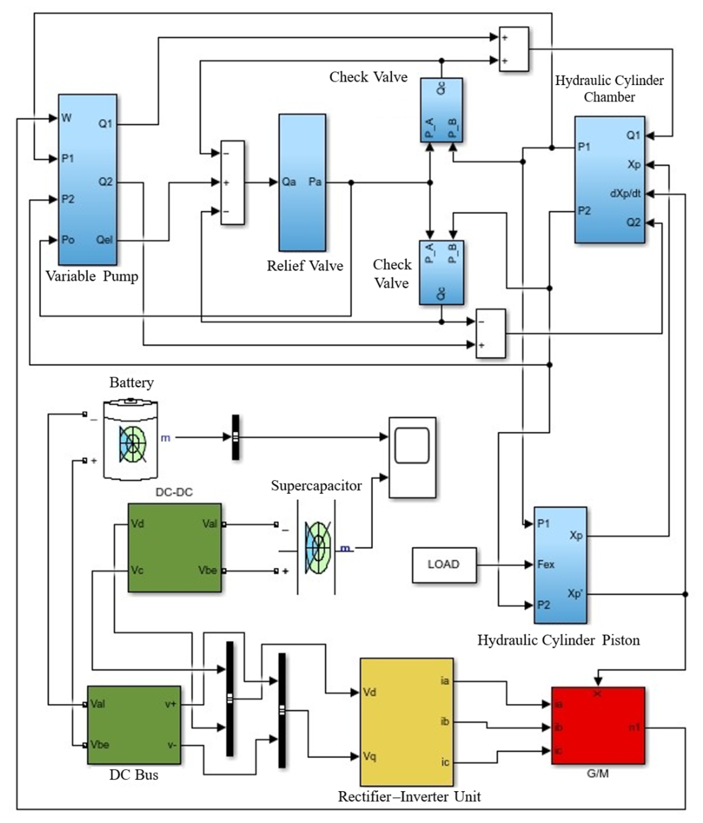
Based on the mathematical models of the key components, an overall simulation model of the electric loader servo pump-controlled unit is established in MATLAB/Simulink R2022b for subsequent dynamic response analysis, sensitivity analysis, and multi-objective parameter optimization.
The simulation model mainly consists of servo motor, variable pump, hydraulic cylinder, and load modules, where electro-mechanical-hydraulic co-simulation is achieved through the coupling among these modules. The developed model can effectively reflect system dynamic response characteristics and energy transmission behavior, providing a simulation basis for subsequent parameter optimization studies. The developed system simulation model is shown in Figure 2.
In summary, mathematical models of the key components of the electric loader servo pump-controlled unit are established, and an overall simulation model is developed to provide a theoretical basis for subsequent dynamic response analysis, Sobol sensitivity analysis, and NSGA-II-based multi-objective parameter optimization.

3. Sensitivity Analysis of the Servo Pump-Controlled Unit Based on the Sobol Method

3.1. Dynamic Response and Energy Efficiency Analysis

The dynamic response performance and energy transmission efficiency of the servo pump-controlled unit directly determine the operating performance of the electric loader hydraulic system. Due to the strong electro-mechanical-hydraulic coupling characteristics, variations in different parameters significantly affect system dynamics and energy loss. Therefore, it is necessary to establish appropriate performance evaluation indices to provide a basis for subsequent sensitivity analysis and parameter optimization.
System dynamic response performance mainly reflects the ability of the system to track variations in input signals. In this study, settling time and overshoot are selected as evaluation indices for dynamic performance. The settling time is defined as:
t s = t s t e a d y t 0
The percentage overshoot is defined as:
M p = y max y s s y s s × 100 %
where y max denotes the maximum system output, and y s s represents the steady-state output value.
To analyze the system’s energy utilization capability, this paper investigates the efficiency of the servo motor and the variable displacement piston pump separately.
  • Servo Motor Efficiency
During the normal operation of a servo motor, three primary types of energy losses occur: mechanical losses, copper losses, and iron losses.
Mechanical loss, denoted as Pm, is primarily caused by friction in the bearings during the support of rotor motion:
P m = C b D m 3 ω
where Cb denotes the bearing–load correlation coefficient, Dm denotes the bearing diameter, and ω denotes the angular velocity of the servo motor bearing.
The power loss generated when the stator current flows through the motor windings is referred to as copper loss. Since the high-frequency copper loss is negligible due to the low operating frequency, this paper considers only the fundamental copper loss, denoted as PCu, when investigating the loss characteristics of the servo motor. Its mathematical expression is given as follows:
P C u = m I 2 R
where m denotes the number of phases of the servo motor, I denotes the phase current, and R denotes the resistance of each phase winding.
The energy loss generated in the stator core under the action of an alternating magnetic field is referred to as iron loss, denoted as PFe. The mathematical model of iron loss can be expressed as follows:
P F e = K h f B m + K c f 2 B m 2 + K e f 1.5 B m 1.5
where Kh denotes the hysteresis loss coefficient, Kc denotes the eddy current loss coefficient, Ke denotes the excess loss coefficient, f denotes the magnetic field frequency, and Bm denotes the amplitude of the magnetic flux density.
The overall efficiency of the servo motor, denoted as ƞ1, can be expressed as:
η 1 = T e ω T e ω + P m + P C u + P F e
2.
Variable Displacement Piston Pump Efficiency
The efficiency of the variable displacement piston pump, denoted as ƞ2, depends on its volumetric efficiency ƞm and mechanical efficiency ƞv. The volumetric efficiency can be expressed as:
η v = 1 D p n p Q L 1 + Q L 2 + Q L 3 + Q c
where QL1 denotes the leakage flow rate of the piston–cylinder pair, QL2 denotes the leakage flow rate of the slipper–swash plate pair, QL3 denotes the leakage flow rate of the valve plate pair, and Qc denotes the flow loss caused by fluid compressibility.
The mechanical efficiency can be expressed as:
η m = N t N t + N c + N V + N s
where Nt is the output power of the variable displacement piston pump, Nc is the friction power loss of the piston–cylinder pair, Ns is the friction power loss of the slipper–swash plate pair, and NV is the friction power loss of the valve plate pair.
The total efficiency of the variable displacement pump is the product of the volumetric efficiency and the mechanical efficiency, and can be expressed as:
η 2 = η m η v
The efficiency characteristic ƞ3 of the servo pump-controlled unit is mainly determined by the performance of the electro-proportional variable displacement piston pump and the servo motor. Its expression is:
η 3 = η 1 η 2
It can be observed from the above analysis that system dynamic performance and energy efficiency are jointly influenced by parameters such as pump displacement, leakage coefficient, hydraulic oil bulk modulus, and servo motor rotational inertia. Therefore, further analysis is required to evaluate the influence of each parameter on system performance.

3.2. Sobol Global Sensitivity Analysis

Due to the strong nonlinearities and parameter coupling characteristics of the electric loader servo pump-controlled unit, conventional local sensitivity analysis methods are insufficient to accurately characterize the influence of parameter variations on overall system performance.
Therefore, Sobol global sensitivity analysis is adopted to quantitatively evaluate key parameters and identify sensitive parameters that significantly affect system dynamic performance and energy transmission efficiency.
Sobol analysis is a variance-based global sensitivity analysis method that quantitatively evaluates the contributions of individual parameters and their interactions to system outputs. For a system output function:
Y = f X 1 , X 2 , , X n
where X i denotes the system input parameters, and Y represents the system output response.
The total variance of the system output can be expressed as:
V Y = i = 1 n V i + i < j V i j + + V 12 n
where V i represents the variance contribution of an individual parameter to the system output, and V i j denotes the variance contribution caused by parameter interactions.
The first-order Sobol sensitivity index is defined as:
S i = V i V Y
This index is used to measure the independent contribution of an individual parameter to the system output.
Considering parameter interactions, the total Sobol sensitivity index is defined as:
S T i = 1 V i V Y
where V ~ i represents the output variance caused by all parameters except parameter X i .
A larger sensitivity index indicates a greater influence of the corresponding parameter on system performance.
This study adopts the Sobol global sensitivity analysis method based on the Saltelli sampling strategy, combined with Monte Carlo random sampling to achieve uniform coverage of the high-dimensional parameter space. The sample size for each parameter was set to N = 10,000, and a stratified sampling approach was employed to improve computational efficiency and stability.
To ensure the reliability of the calculation results, a convergence criterion was introduced: the results were considered converged when the variation in the first-order sensitivity indices was less than 5% after three consecutive sample size expansions. Convergence analysis verified that the selected sample size meets the accuracy requirements for system sensitivity assessment.
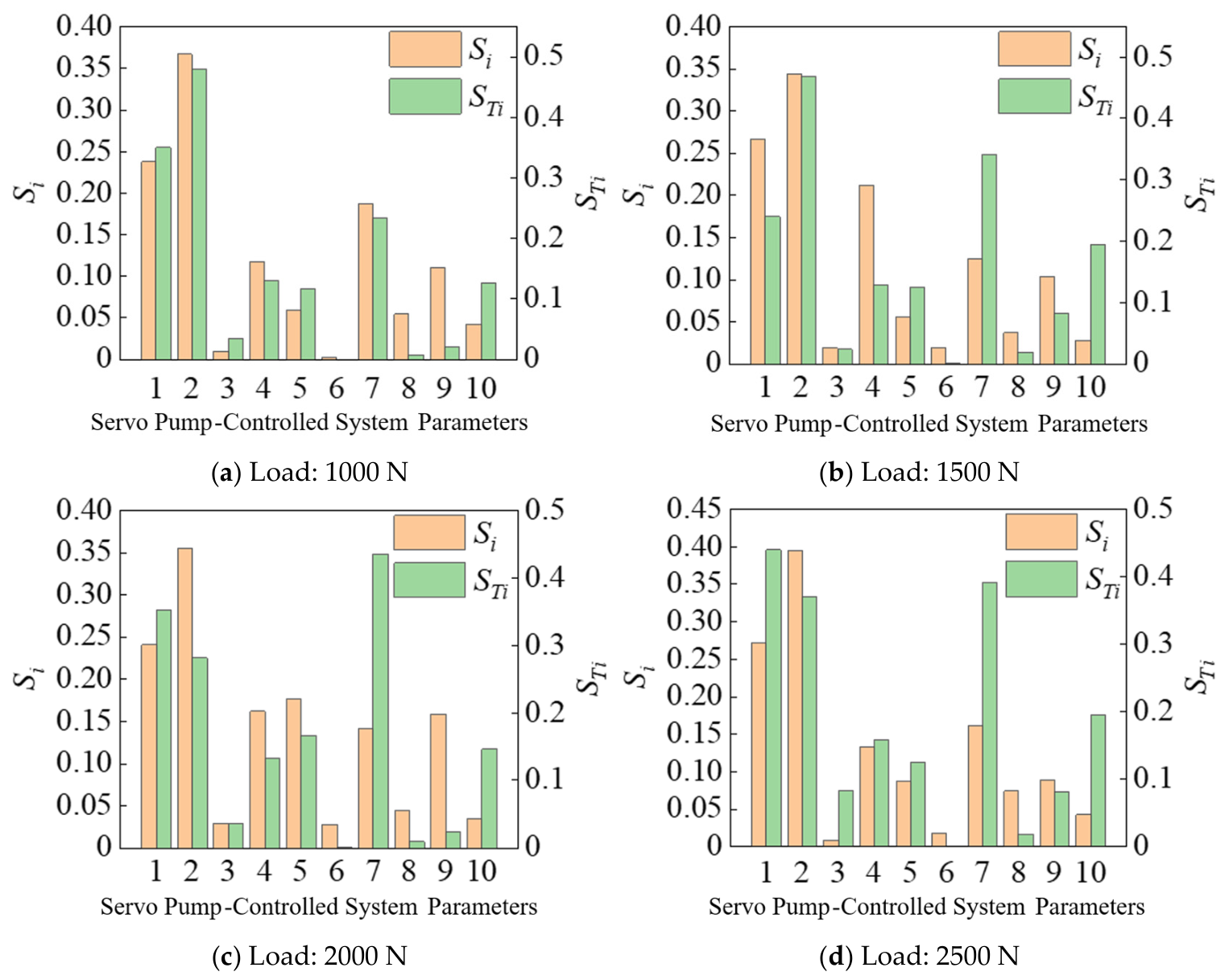
Combined with the structural characteristics and mathematical models of the servo pump-controlled unit, parameters including pump displacement, servo motor rotational inertia, effective cylinder area, hydraulic oil bulk modulus, and system leakage coefficient are selected for sensitivity analysis. Based on the MATLAB/Simulink platform, a co-simulation model is established to perform Sobol global sensitivity analysis on system dynamic performance and energy transmission efficiency. The parameter ranges of the servo pump-controlled unit are listed in Table 1.
Using the dynamic characteristic output as the objective function, the first-order and total sensitivities of each parameter of the servo pump control unit under different operating conditions were calculated. The results of the first-order sensitivity calculations are shown in Table 2, and the results of the total sensitivity calculations are shown in Table 3.
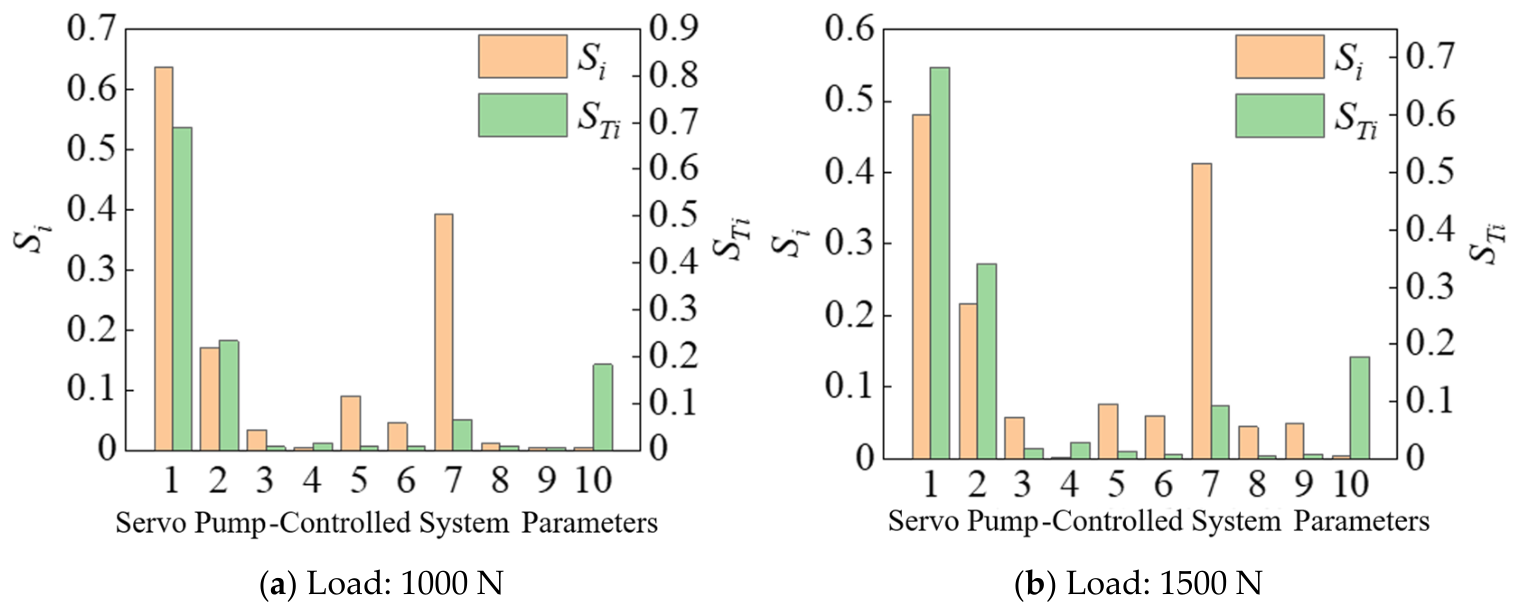
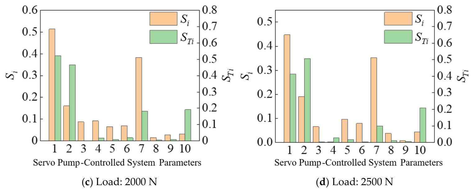
Using the system efficiency output as the objective function, the first-order sensitivity and total sensitivity of each parameter of the servo pump control unit under different operating conditions were calculated. The calculation results of the first-order sensitivity are shown in Table 4, and the calculation results of the total sensitivity are shown in Table 5.
The analysis results indicate that pump displacement and servo motor rotational inertia have the most significant effects on system dynamic performance. Specifically, increasing pump displacement improves flow output capability and reduces settling time, whereas larger rotational inertia decreases system response speed. In terms of energy efficiency, the system leakage coefficient and hydraulic oil bulk modulus have greater influences on energy transmission efficiency. An increase in leakage coefficient leads to higher energy loss, while the hydraulic oil bulk modulus affects pressure build-up speed and energy transmission stability. The global sensitivity results of the dynamic characteristics of the servo pump-controlled unit are shown in Figure 3.
In addition, significant interactions exist among some parameters, indicating that parameter optimization of servo pump-controlled systems is a typical multi-parameter coupling optimization problem. Therefore, single-parameter optimization is insufficient to simultaneously balance dynamic response performance and energy efficiency, and multi-objective optimization methods are required for coordinated optimization of key parameters. The global sensitivity results of the energy efficiency parameters of the servo pump-controlled unit are shown in Figure 4.

4. NSGA-II-Based Multi-Objective Parameter Optimization of the Servo Pump-Controlled Unit

4.1. Multi-Objective Optimization Problem Formulation

Based on the Sobol global sensitivity analysis in Chapter 3, parameters such as pump displacement, effective cylinder area, servo motor rotational inertia, and system leakage coefficient have significant influences on the dynamic response performance and energy transmission efficiency of the servo pump-controlled unit. Meanwhile, significant interactions exist among some parameters, making it difficult to simultaneously improve dynamic performance and energy efficiency through single-parameter adjustment. Therefore, to further improve overall system performance, the NSGA-II algorithm is employed for multi-objective coordinated optimization of key parameters in the servo pump-controlled unit.
In this study, system dynamic response performance and energy transmission efficiency are selected as optimization objectives. Dynamic performance is comprehensively evaluated using settling time and overshoot, and the objective function is defined as:
f 1 = ω 1 t s + ω 2 M p
where t s denotes the system settling time, M p represents the system overshoot, and ω1, ω2 denote the weighting coefficients.
The objective function for system energy efficiency is defined as:
f 2 = 1 η
where η denotes the system energy transmission efficiency.
Therefore, the optimization goal can be defined as T = 1 / f , α = 1 η 3 . The objective function can be defined as:
min α T e , D p , A p , T T e , D p , A p
where X represents the parameter vector to be optimized.
Combined with the sensitivity analysis results in Chapter 3, pump displacement D p , effective cylinder area A , servo motor rotational inertia J , and system leakage coefficient C are selected as optimization variables. The parameter ranges are determined according to practical operating conditions and engineering experience, as listed in Table 1.
To ensure system stability and engineering feasibility, the following constraints are imposed on the optimization variables:
X min X X max
In addition, constraints on system pressure and response stability should also be satisfied to avoid excessive pressure and dynamic oscillations.
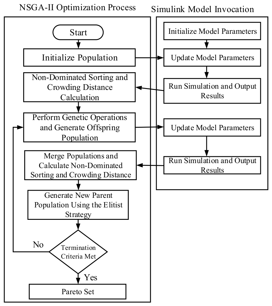
The NSGA-II algorithm is a multi-objective optimization algorithm based on non-dominated sorting, which has advantages such as strong global search capability and well-distributed Pareto solutions. By employing fast non-dominated sorting and crowding distance calculation, the algorithm can effectively solve multi-objective optimization problems. In this study, an NSGA-II optimization model is established in MATLAB and coupled with the servo pump-controlled system simulation model to achieve the automatic optimization of key system parameters. The principle of the NSGA-II algorithm is illustrated in Figure 5.
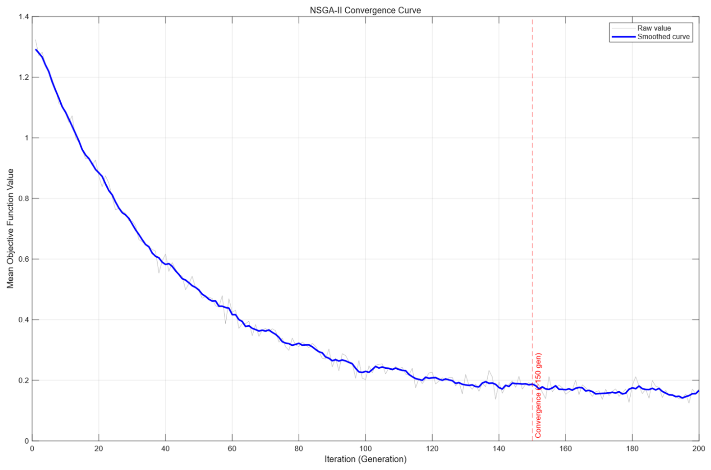
To ensure the stability and convergence of the optimization results, the parameters of the NSGA-II algorithm were set as follows: population size of 100, maximum number of iterations of 200, crossover probability of 0.9, and mutation probability of 0.1. Simulated binary crossover and polynomial mutation operators were adopted. The algorithm was run 20 times, and the average results were taken to reduce the influence of random errors.
To verify the convergence performance of the NSGA-II algorithm, the variation in the mean objective function value of the Pareto front solution set was recorded across generations. As shown in Figure 6, with the increase in the number of iterations, the objective function gradually converged and stabilized after approximately 150 generations, indicating that the algorithm exhibits good convergence and stability.

4.2. Optimization Results and Analysis

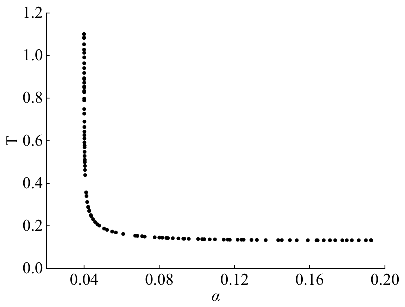
Based on the MATLAB/Simulink co-simulation platform, the NSGA-II algorithm is employed to perform multi-objective optimization of key parameters in the servo pump-controlled unit, obtaining the Pareto optimal solution set between dynamic response performance and energy transmission efficiency, as shown in Figure 7.
It can be observed from the Pareto front that there exists a clear trade-off between dynamic response performance and energy efficiency. Specifically, improving dynamic response performance tends to increase energy loss, whereas excessive pursuit of energy efficiency may reduce system response speed. Therefore, a reasonable balance between dynamic performance and energy efficiency is required.
The results demonstrate that system energy loss is significantly reduced after optimization, leading to improved energy transmission efficiency. This improvement is mainly attributed to the more reasonable matching between pump displacement and key system parameters, which reduces throttling losses and pressure fluctuations.
In summary, the proposed multi-objective parameter optimization method based on Sobol sensitivity analysis and the NSGA-II algorithm effectively improves the dynamic response performance and energy efficiency of the electric loader servo pump-controlled unit, achieving overall performance enhancement and providing an effective approach for parameter matching of high-efficiency hydraulic drive systems in electric construction machinery.

5. Experimental Validation and Analysis

5.1. Experimental Platform Setup

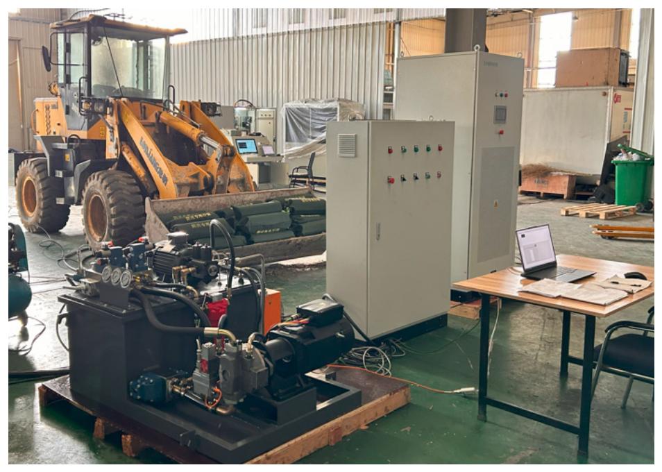
To validate the effectiveness of the proposed multi-objective parameter optimization method based on Sobol sensitivity analysis and the NSGA-II algorithm, an experimental platform for the electric loader servo pump-controlled unit is established to evaluate system dynamic response performance and energy transmission efficiency.
The experimental platform mainly consists of a servo motor, variable pump, hydraulic cylinder, hydraulic control circuit, data acquisition module, and host computer control system. The experimental platform is illustrated in Figure 8. The servo motor is used to drive the variable pump, while the hydraulic cylinder is employed to simulate actual loader load conditions.
Pressure and displacement sensors are utilized to acquire system operating parameters in real time. The host computer outputs control commands and records experimental data through the controller.
During the experiments, the dynamic response characteristics and energy efficiency of the servo pump-controlled unit before and after optimization are evaluated under different load conditions, and comparative analyses are conducted.
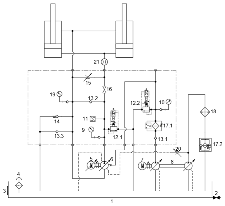
The operating principle of the servo pump-controlled unit is illustrated in Figure 9. The hybrid power supply serves as the power source for the servo motor, where the battery provides the primary energy supply and the supercapacitor is used for peak power support and regenerative energy recovery. The servo motor drives the electro-hydraulic variable pump to deliver hydraulic oil, thereby actuating the hydraulic cylinder to lift the loader boom, while the relief valve is employed to protect the system from excessive pressure.
Since the hydraulic cylinder of the loader is asymmetric, the variable pump draws oil from the tank through check valve 13.3 during boom lifting. During boom lowering, excess oil is discharged into the tank through check valve 14. When the boom reaches its lower limit, no oil enters the variable pump/motor from the rodless chamber of the hydraulic cylinder. Under this condition, the variable pump/motor continues operating and draws oil from the tank through check valve 13.2.
The system adopts a hierarchical control strategy. At the upper computer level, control commands are configured through the human–machine interface and transmitted to the motion controller. As the core processing unit, the motion controller acquires analog signals from pressure sensors and flow sensors in real time. Based on the control algorithm outputs, precise control is achieved through multiple output channels, where digital output channels are used to control the switching states of solenoid valves, while the EtherCAT communication interface transmits motor control commands to the servo drive.
In the experimental platform, high-precision pressure sensors and flow sensors were employed for data acquisition. The pressure sensor has a range of 0–25 MPa with an accuracy of ±0.25% FS, and the flow sensor has a range of 0–60 L/min with an accuracy of ±0.5% FS. The data acquisition system utilized an NI data acquisition card with a maximum sampling frequency of up to 10 kHz and a resolution of 16 bit, ensuring the real-time performance and accuracy of the experimental data.

5.2. Experimental Results and Analysis of the Servo Pump-Controlled Unit

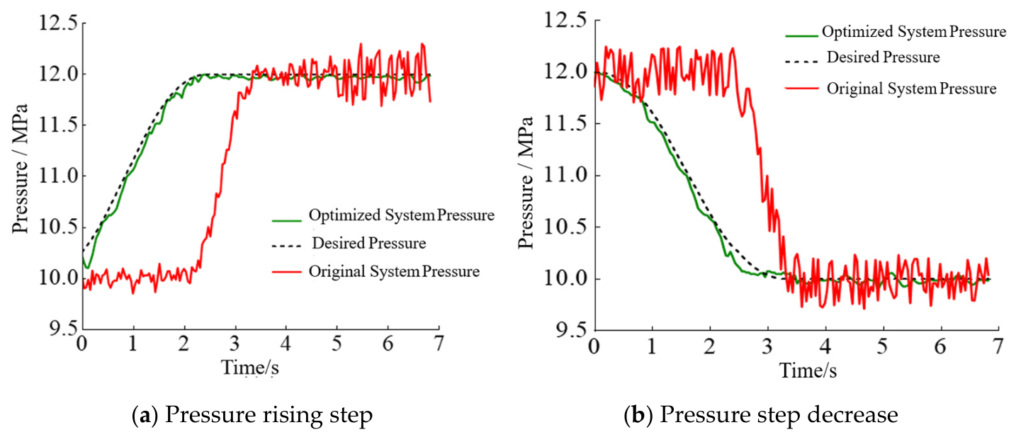
Pressure response tests are conducted to experimentally validate the dynamic performance of the servo pump-controlled unit. Step pressure signals are employed as system excitations to investigate the differences in dynamic response characteristics before and after optimization. During the tests, system pressure responses are collected in real time using high-precision pressure sensors, and comparative analyses are performed in combination with simulation results. Specifically, a step pressure input from 10 MPa to 12 MPa is applied to obtain the pressure tracking response, with the results shown in Figure 10a. Similarly, a step pressure input from 12 MPa to 10 MPa is applied, and the corresponding pressure tracking results are presented in Figure 10b.
The experimental results indicate that the original system exhibits obvious pressure tracking errors under this operating condition, requiring a longer time to reach the desired pressure and showing larger pressure fluctuations, with a maximum fluctuation amplitude of approximately ±0.5 MPa. In contrast, the optimized system demonstrates superior performance, with significantly reduced pressure tracking errors and pressure fluctuations effectively limited within 0.1 MPa, indicating higher stability and accuracy. Comparative analysis further shows that the optimized system achieves substantial improvements in dynamic response performance by reducing response time and suppressing pressure fluctuations, thereby verifying the effectiveness of the proposed parameter optimization strategy.
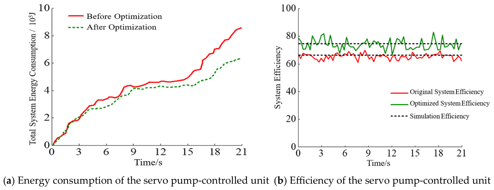
Energy consumption tests are conducted on the experimental platform to compare the servo pump-controlled unit before and after optimization, and the corresponding results are shown in Figure 11a. Based on the measured energy consumption, system efficiency is calculated and compared with that of the original servo pump-controlled unit, resulting in the efficiency comparison curves shown in Figure 11b. Comparative analysis of system efficiency is then performed to verify the effectiveness of the proposed multi-objective parameter optimization method.
This study optimizes the parameter matching of the servo pump-controlled unit based on sensitivity analysis and multi-objective optimization methods, followed by energy consumption and efficiency evaluation. As shown in Figure 5, Figure 6, Figure 7, Figure 8, Figure 9, Figure 10, Figure 11a, the energy consumption of the original servo pump-controlled unit is 849 kJ, while that of the optimized system decreases to 625 kJ, corresponding to a reduction of 224 kJ. Furthermore, Figure 5, Figure 6, Figure 7, Figure 8, Figure 9, Figure 10, Figure 11b shows that the efficiency of the optimized servo pump-controlled unit reaches 77.28%, representing an improvement of approximately 9% compared with the original system. These results verify the effectiveness of the proposed parameter optimization method. By identifying key parameters affecting system efficiency through sensitivity analysis and combining them with multi-objective optimization, comprehensive performance improvement is achieved. The results demonstrate the feasibility of the proposed optimization strategy and provide theoretical and practical guidance for improving the energy efficiency of servo pump-controlled units.

6. Conclusions and Future Work

6.1. Conclusions

To address insufficient dynamic response, complex parameter coupling, and low energy efficiency in the electric loader servo pump-controlled unit, a multi-objective parameter optimization method based on Sobol sensitivity analysis and the NSGA-II algorithm is proposed. Simulation and experimental results show that the optimized system achieves improved dynamic response and stability. During step pressure tests, pressure fluctuations are reduced from ±0.5 MPa to ±0.1 MPa, while response speed is significantly improved. Meanwhile, system energy consumption decreases from 1614 kJ to 1326 kJ, resulting in improved energy efficiency. These results demonstrate that the proposed method effectively balances dynamic performance and energy efficiency, reduces energy loss, and improves system stability, verifying its effectiveness for the parameter optimization of electric loader servo pump-controlled systems.

6.2. Future Work

Although the multi-objective optimization method based on Sobol sensitivity analysis and the NSGA-II algorithm proposed in this paper has achieved favorable optimization results in the servo pump-controlled system of an electric loader, there is still room for further research. Future work will focus on the following aspects:
(1) Further introducing a modeling approach that integrates data-driven methods with physical models to improve the system modeling accuracy under complex operating conditions;
(2) Investigating online parameter optimization and adaptive control methods to realize real-time adjustment of key parameters, thereby adapting to variations in unsteady operating conditions;
(3) Combining actual engineering operation data to verify the long-term stability and robustness of the optimization strategy, so as to enhance the engineering applicability of the method.

6.3. Limitations

This study still has certain limitations. First, in the process of mathematical modeling, the hydraulic oil temperature, system leakage characteristics, and friction factors were simplified, with the physical property parameters of the oil assumed to remain constant. This deviates to some extent from the parameter drift caused by temperature variations in actual operating conditions. Second, the simulation model was built on the MATLAB/Simulink platform, primarily considering ideal boundary conditions, and did not fully incorporate pipeline elastic deformation and complex nonlinear disturbance factors. Finally, although the experimental platform has verified the effectiveness of the proposed method, the range of experimental operating conditions remains limited and has not yet covered extreme loads and long-duration continuous operation scenarios.

Author Contributions

H.Z.: Conceptualization, Methodology, Software, Formal analysis, Investigation, Validation, Visualization, Writing—original draft. G.C.: Conceptualization, Methodology, Supervision, Project administration, Funding acquisition, Writing—review and editing. K.L.: Methodology, Formal analysis. K.Z.: Software, Validation. J.Z.: Data curation, Formal analysis. Y.D.: Investigation, Validation. S.T.: Investigation, Resources. B.L.: Data curation, Visualization. J.C.: Software, Resources. Y.L.: Investigation, Data curation. Y.Z.: Resources, Resources. T.J.: Visualization, Writing—review and editing. X.Y.: Writing—review and editing, Validation. All authors have read and agreed to the published version of the manuscript.

Funding

This study was funded by the Special Project for Serving Local Areas by the Tianchi Talent Introduction Programme (2024XGYTCYC02), the Xinjiang Uygur Autonomous Region Science and Technology Development Program (2025LQ04002), the Key Research and Development Program of the Xinjiang Uygur Autonomous Region (2024B01002-1) and the Outstanding Young Scientists Fund of the Natural Science Foundation of the Xinjiang Uygur Autonomous Region (2025D01E18).

Data Availability Statement

Data are available on request due to restrictions. The data presented in this study are available on request from the corresponding author.

Conflicts of Interest

The authors declare no conflict of interest.

References

  1. Lin, T.; Wang, Q.; Hu, B.; Gong, W. Development of hybrid powered hydraulic construction machinery. Autom. Constr. 2010, 19, 11–19. [Google Scholar] [CrossRef]
  2. Xu, B.; Cheng, M. Motion control of multi-actuator hydraulic systems for mobile machineries: Recent advancements and future trends. Front. Mech. Eng. 2018, 13, 151–166. [Google Scholar] [CrossRef]
  3. Bhola, M.; Wrat, G. Energy-Efficient Hydraulics in Heavy Machinery: Technologies, Challenges, and Future Directions. Sustainability 2025, 18, 302. [Google Scholar] [CrossRef]
  4. Gong, J.; Zhang, D.; Liu, C.; Zhao, Y.; Hu, P.; Quan, W. Optimization of electro-hydraulic energy-savings in mobile machinery. Autom. Constr. 2019, 98, 132–145. [Google Scholar] [CrossRef]
  5. Li, J.; Kong, L.; Liang, H.; Li, W. Review of development and characteristics research on electro-hydraulic servo system. Recent Pat. Eng. 2024, 18, 140–154. [Google Scholar] [CrossRef]
  6. Geffroy, S.; Brautlacht, A.; Wegner, S.; Gels, S.; Schmitz, K. Experimental validation of a new design concept for the increase of efficiency of the hydraulic drive system in mobile working machines. In IOP Conference Series: Materials Science and Engineering; IOP Publishing: Bristol, UK, 2021. [Google Scholar] [CrossRef]
  7. Yang, B.; Lu, Y.; Jiang, H.; Ling, Z.; Li, T.; Liu, H.; Ouyang, X. Quantitative comparative study on the performance of a valve-controlled actuator and electro-hydrostatic actuator. Actuators 2024, 13, 118. [Google Scholar] [CrossRef]
  8. Zakharov, V.; Minav, T. Influence of hydraulics on electric drive operational characteristics in pump-controlled actuators. Actuators 2021, 10, 321. [Google Scholar] [CrossRef]
  9. Yu, B.; Zhu, Q.; Yao, J.; Zhang, J.-X.; Huang, Z.-P.; Jin, Z.; Wang, X. Design, mathematical modeling and force control for electro-hydraulic servo system with pump-valve compound drive. IEEE Access 2020, 8, 171988–172005. [Google Scholar] [CrossRef]
  10. Yan, Z. Characteristics of high energy-efficient Electro-hydraulic power source driven by servo motor and variable pump. Proc. Inst. Mech. Eng. Part C J. Mech. Eng. Sci. 2023, 237, 1525–1536. [Google Scholar] [CrossRef]
  11. Zad, H.S.; Ulasyar, A.; Zohaib, A.A. Robust Model Predictive position Control of direct drive electro-hydraulic servo system. In Proceedings of the 2016 International Conference on Intelligent Systems Engineering (ICISE); IEEE: Piscataway, NJ, USA, 2016. [Google Scholar] [CrossRef]
  12. Chiang, M. A novel pitch control system for a wind turbine driven by a variable-speed pump-controlled hydraulic servo system. Mechatronics 2011, 21, 753–761. [Google Scholar] [CrossRef]
  13. Luo, G.; Görges, D. Modeling and Adaptive Robust Force Control of a Pump-Controlled Electro-Hydraulic Actuator for an Active Suspension System. In Proceedings of the 2019 IEEE Conference on Control Technology and Applications (CCTA); IEEE: Piscataway, NJ, USA, 2019. [Google Scholar] [CrossRef]
  14. Kumar, M. A survey on electro hydrostatic actuator: Architecture and way ahead. Mater. Today Proc. 2021, 45, 6057–6063. [Google Scholar] [CrossRef]
  15. Liem, D.T.; Truong, D.Q.; Park, H.G.; Ahn, K.K. A feedforward neural network fuzzy grey predictor-based controller for force control of an electro-hydraulic actuator. Int. J. Precis. Eng. Manuf. 2016, 17, 309–321. [Google Scholar] [CrossRef]
  16. Ba, D.X.; Dinh, T.Q.; Bae, J.; Ahn, K.K. An effective disturbance-observer-based nonlinear controller for a pump-controlled hydraulic system. IEEE/ASME Trans. Mechatron. 2019, 25, 32–43. [Google Scholar]
  17. Lee, W.Y.; Kim, M.J.; Chung, W.K. An approach to development of electro hydrostatic actuator (eha)-based robot joints. In Proceedings of the 2015 IEEE International Conference on Industrial Technology (ICIT); IEEE: Piscataway, NJ, USA, 2015. [Google Scholar] [CrossRef]
  18. Moulik, B.; Karbaschian, M.A.; Soffker, D. Size and parameter adjustment of a hybrid hydraulic powertrain using a global multi-objective optimization algorithm. In Proceedings of the 2013 IEEE Vehicle Power and Propulsion Conference (VPPC); IEEE: Piscataway, NJ, USA, 2013. [Google Scholar] [CrossRef]
  19. Ali, M.U.; Zafar, A.; Nengroo, S.H.; Hussain, S.; Kim, H.-J. Effect of sensors sensitivity on lithium-ion battery modeled parameters and state of charge: A comparative study. Electronics 2019, 8, 709. [Google Scholar] [CrossRef]
  20. Baghestan, K.; Rezaei, S.M.; Talebi, H.A.; Zareinejad, M. An energy-saving nonlinear position control strategy for electro-hydraulic servo systems. ISA Trans. 2015, 59, 268–279. [Google Scholar] [CrossRef] [PubMed]
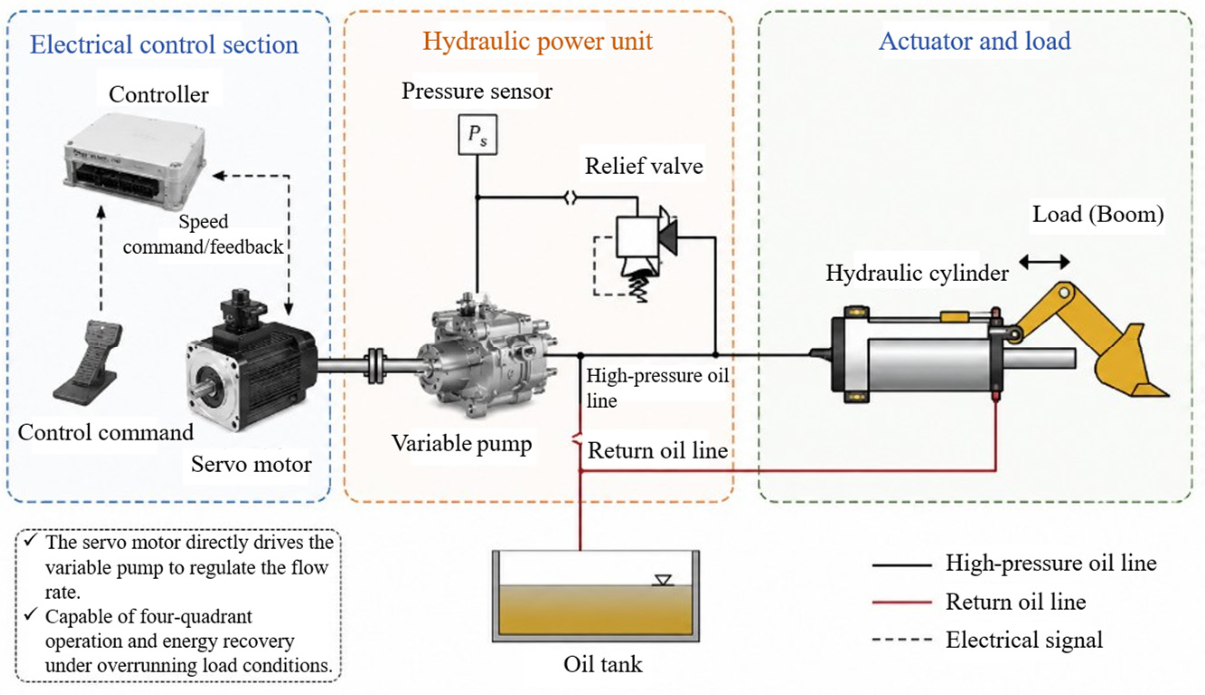
Figure 1. Structure of the electric loader servo pump-controlled unit.
Processes 14 02221 g001
Figure 2. System simulation model.
Processes 14 02221 g002
Figure 3. Global sensitivity of dynamic characteristics for parameters of the servo pump-controlled unit.
Processes 14 02221 g003
Figure 4. Global sensitivity results of energy efficiency of the servo pump-controlled unit.
Processes 14 02221 g004aProcesses 14 02221 g004b
Figure 5. Principle of the NSGA-II algorithm.
Processes 14 02221 g005
Figure 6. Convergence curve of the mean objective function value.
Processes 14 02221 g006
Figure 7. Pareto optimal solution set.
Processes 14 02221 g007
Figure 8. Structure of the experimental platform.
Processes 14 02221 g008
Figure 9. Operating principle of the servo pump-controlled unit. 1—oil tank; 2—ball valve; 3—oil level/temperature gauge; 4—air filter; 5—servo motor; 6—proportional variable piston pump; 7—three-phase motor; 8—double variable vane pump; 9—high-pressure gauge; 10—medium-pressure gauge; 11—pressure sensor; 12—relief unloading valve; 13—check valve; 14—back pressure check valve; 15—adjustable throttle valve; 16—manual ball valve; 17—filter; 18—air cooler; 19—low-pressure gauge; 20—tube throttle valve; 21—flow sensor.
Processes 14 02221 g009
Figure 10. Pressure response curves under step signals.
Processes 14 02221 g010
Figure 11. Energy consumption/efficiency curve.
Processes 14 02221 g011
Table 1. Parameter ranges of the servo pump-controlled unit.
ParameterSymbolMaximum ValueMinimum Value
Hydraulic Cylinder Area/m2Ap14735
Pump Displacement/(L/min)Dp322
Leakage Coefficient/[L/(min/MPa)]C2.01 × 10−111.98 × 10⁻¹¹
Hydraulic Cylinder and Pipeline Volume/LV1810
Viscous Damping Coefficient/[N·s/m]Bm100.1
Effective Bulk Modulus/Paβe1.2 × 1098 × 108
Motor Torque/(N·m)Te1104
Stator Winding Resistance/ΩRa0.9760.1098
Motor Torque Constant/[(N·m)/A]Kt2.720.01
Equivalent Rotor Rotational Inertia/(kg·m2)J0.30.01
Table 2. First-order sensitivity of the dynamic characteristics of servo pump control unit parameters under different operating conditions.
Item NumberParameterLoad of 1000 NLoad of 1500 NLoad of 2000 NLoad of 2500 N
1Ap0.23770.26720.24050.2717
2Dp0.36710.34350.35470.3953
3C0.00910.01880.02910.0089
4V0.11690.21140.16230.1331
5Bm0.05880.05560.17640.0866
6βe0.00250.01930.02780.0174
7Te0.18690.12420.14120.1608
8Ra0.05450.03670.04390.0745
9Kt0.11010.10290.15850.0892
10J0.04230.02810.03500.0427
Table 3. Overall sensitivity of dynamic characteristics of servo pump control unit parameters under various operating conditions.
Item NumberParameterLoad of 1000 NLoad of 1500 NLoad of 2000 NLoad of 2500 N
1Ap0.35050.24020.35210.4402
2Dp0.47990.46980.28150.3698
3C0.03460.02310.03520.0831
4V0.13050.12890.13210.1589
5Bm0.11570.12420.16680.1242
6βe0.00030.00050.00090.0005
7Te0.23330.34170.43540.3917
8Ra0.00750.01780.00920.0178
9Kt0.02070.08150.02290.0815
10J0.12570.19430.1467 0.1943
Table 4. First-order sensitivity of the efficiency of servo pump control unit parameters under different operating conditions.
Item NumberParameterLoad of 1000 NLoad of 1500 NLoad of 2000 NLoad of 2500 N
1Ap0.63650.48030.51440.4476
2Dp0.17080.21580.16060.1909
3C0.03430.05820.08790.0648
4V0.00280.00190.09210.0025
5Bm0.08990.07710.06630.0959
6βe0.04510.05950.06970.0784
7Te0.39260.41240.38330.3518
8Ra0.01070.04490.01520.0367
9Kt0.00320.04860.02880.00769
10J0.00440.00370.03150.0434
Table 5. Total sensitivity of servo pump control unit parameter efficiency under various operating conditions.
Item NumberParameterLoad of 1000 NLoad of 1500 NLoad of 2000 NLoad of 2500 N
1Ap0.68890.68340.52230.4145
2Dp0.23330.34170.46580.5073
3C0.00670.01680.00110.0033
4V0.01440.02910.01760.0281
5Bm0.00760.01250.00830.0166
6βe0.00790.00730.01920.0014
7Te0.06380.0940.1830.0997
8Ra0.00860.00560.00670.0122
9Kt0.00510.00920.00880.005
10J0.18220.17890.19190.2079
Disclaimer/Publisher’s Note: The statements, opinions and data contained in all publications are solely those of the individual author(s) and contributor(s) and not of MDPI and/or the editor(s). MDPI and/or the editor(s) disclaim responsibility for any injury to people or property resulting from any ideas, methods, instructions or products referred to in the content.