Article

Investigation into the Heat Transfer Mechanism via Mixed Coherent Structures Induced by Vortex Generators Punched with Multi-Holes

1
School of Intelligent Manufacturing, Wuhan Technical University, Wuhan 430074, China
2
School of Mechanical Engineering, Wuhan University of Science and Technology, Wuhan 430081, China
*
Authors to whom correspondence should be addressed.
Processes 2026, 14(13), 2217; https://doi.org/10.3390/pr14132217
Submission received: 6 June 2026 / Revised: 1 July 2026 / Accepted: 3 July 2026 / Published: 7 July 2026

Abstract

Perforated vortex generators have been widely investigated as a passive heat transfer enhancement technique due to their ability to modify local flow structures through perforation-induced bleed flows. However, their thermo-hydraulic performance is strongly dependent on geometric and flow conditions, and a consistent enhancement effect has not been universally observed. In this study, the mechanism of heat transfer enhancement as well as flow behaviors associated with perforation-induced bleed flows are elucidated through an analysis of the generation and interference behaviors of mixed coherent structures induced by vortex generators punched with multi-holes (PMHVGs). The results showed that the beveled edges of the PMHVGs are responsible for initiating the formation of mixed coherent structures, while local fluid-pressure gradients are identified as the primary driving factor behind their development. Once formed, the perforation-induced bleed flows exert interference on other coherent structures, thereby reducing both their formation intensity and interaction strength. After their generation, the mixed coherent structures contribute to thermal energy transport within the flow through their near-wall ejection and sweep motions.

1. Introduction

With the aggravation of the energy crisis and environmental issues, the improvement of heat transfer efficiency and the reduction in energy consumption have been regarded as significant research subjects in the field of thermal science and engineering. The heat exchanger has been considered a core component in energy conversion and thermal management systems, and its heat transfer and flow characteristics have been recognized as directly determine the overall performance and operational economy of the system. However, limitations have been encountered in the structural optimization and performance improvement of conventional heat exchangers, and the simple reliance on geometric compactness has been found insufficient to satisfy the demand for high efficiency and low energy consumption. Against this background, various heat transfer enhancement techniques have been widely investigated, among which passive methods have been especially emphasized due to the absence of additional external energy input. By placing vortex generators (VGs) inside the flow passages, the generation of various vortices can be induced, whereby fluid mixing and thermal boundary layer disturbance can be intensified, and this approach has been considered as an efficient and feasible enhancement strategy. It has been demonstrated that VGs are capable of significantly improving both local and overall heat transfer performance, while a compromise between heat transfer enhancement and pressure drop penalty can be achieved under appropriately designed conditions.
Ismail et al. [1] systematically summarized the design, optimization, and application of various VG configurations, including delta winglets, rectangular winglets, and perforated types, highlighting their potential in balancing thermal efficiency and hydraulic performance. Zheng et al. [2] proposed a novel self-join winglet VG and assessed its thermo-hydraulic performance in circular tubes through both simulations and experiments. Their findings revealed that the new configuration induced multiple vortices inside the tube, leading to a 1.50–3.49-fold improvement in heat transfer compared with a plain tube. Wu et al. [3] investigated the influence of multiple V-shaped winglet VGs arranged at different attack angles and layouts. Using a combination of numerical and experimental approaches, they demonstrated that properly arranged multi-V winglets could generate strong longitudinal vortices, markedly increase the Nusselt number, and offer a reasonable trade-off between heat transfer enhancement and pressure drop. Promvonge et al. [4] numerically examined V-type double baffles installed in a square duct. The study indicated that the double-baffle arrangement promoted intense flow disturbances and secondary flows, thereby achieving substantial heat transfer enhancement and improved thermal efficiency across a wide Reynolds number range. Feng et al. [5] carried out a numerical investigation on the influence of multiple delta-winglet VGs in tubes under turbulent conditions (Re = 7577~27,276), in which particular attention was given to the flow structures and heat transfer characteristics associated with different arrangements. In their study, three attack angles (60°, 90°, and 120°), three VG heights (2.1, 3.2, and 4.2 mm), and three numbers of VGs (N = 4, 5, and 6) were considered, and it was found that the optimal thermal enhancement factor (TEF) reached 1.63. The transition process of airflow downstream of delta-winglet VGs in a channel (Re = 400~12,000) was investigated by Younes et al. [6], who reported that the turbulence dissipation rate was observed to increase with downstream distance before exhibiting an exponential decay. The thermo-hydraulic behavior of channels equipped with multiple rows of VGs was numerically examined by Karkaba et al. [7]. Their results suggested that the placement of successive VG rows was capable of further increasing the TEF, with a maximum enhancement of 14%. In the study of Ekrani et al. [8], it was shown that longitudinal vortices were generated near the VG tips and rear sides, which subsequently interacted, merged, and gradually dissipated; this vortex evolution was accompanied by pressure variations in the flow field, which in turn altered the local heat transfer enhancement and pressure drop. Wu et al. [9] applied sinusoidal wavy winglet VGs in a fin-and-tube heat exchanger, where CFD combined with exergy analysis was employed. Their results demonstrated that the presence of VGs induced recirculation zones, within which fluid stagnation caused heat transfer deterioration at the rear edge of the tube and led to locally elevated temperatures, suggesting that the mitigation of recirculation regions could be regarded as an effective strategy to reduce such heat transfer deficiencies.
In order to further mitigate the recirculation zones induced by VGs, several approaches have been proposed, which mainly include: (1) designing VGs with a streamlined shape (where the VG possesses a certain curvature angle from the leading edge to the trailing edge); (2) perforating the VG surface; and (3) employing multiple VG combinations [10]. In the first approach, the streamlined configuration is utilized so that the pressure difference between the front and rear sides of the VG can be reduced, thereby weakening the intensity of the recirculating flow. In the second approach, local jets are induced by the pressure difference generated across the perforated VG surface, through which the formation of recirculation can be suppressed. In the third approach, the interference of vortices generated by multiple VG arrays is exploited to decrease the fluid mass entering the recirculation zones. Among these three strategies, the second one has been regarded as the most economical and effective, and therefore has attracted considerable research attention.
In the research on perforated VGs, current studies have primarily focused on the influence of perforation parameters as well as the flow behavior of mixed vortices under different conditions. Zhou et al. [11] experimentally investigated the effects of perforated VGs with different perforation designs on heat transfer and friction characteristics. It was found that perforations could improve heat transfer performance, but the hole size needed to be properly matched with the VG surface area. Gupta et al. [12] numerically evaluated the influence of perforated rectangular winglets on heat transfer performance, and observed that the heat transfer in tubes equipped with perforated rectangular winglets was enhanced by 34%. Syaiful et al. [13] reported on the enhancement of heat transfer using concave rectangular winglet VGs, and their results indicated that the Nusselt number (Nu) increased by 53.58% compared with a smooth tube when staggered arrangements were applied. Pérez et al. [14] examined flow patterns in a rectangular heat transfer channel equipped with three VG configurations and sixteen different transverse spacings, and it was shown that all configurations enhanced heat transfer while increasing pressure drop, with maximum increases of 12.8% and 17.5%, respectively. Hap et al. [15] proposed a perforated arc-shaped VG and installed it in a rectangular channel to study its thermo-hydraulic performance under turbulent conditions (Re = 6000–18,000). Their results demonstrated that the tube equipped with the new VG achieved a heat transfer enhancement of 2.1 times, accompanied by a pressure drop increase of 3.4 times, and they suggested that the new VG could achieve substantial heat transfer improvement when Re exceeded 13,000.
Göksu and Behçet [16] investigated perforated VGs with structural tapes (combining rectangular VGs and circular holes, with the excess material forming fins) placed at the center of heat transfer tubes. The study considered two perforation angles (15° and 30°), two perforation orientations (forward and backward), and two numbers of perforations (1 and 2). It was found that fins that opened both upward and downward on the flow-facing side contributed more significantly to heat transfer enhancement. Compared with a smooth tube, the 30° windows opened upward and downward achieved an increase of up to 173%, while the open and closed 15° window configuration showed the smallest enhancement of 14%. Wang et al. [17] conducted numerical and experimental studies on fluid flow and heat transfer over perforated VGs, revealing that perforations induced local jets whose subsequent behavior was closely related to the VG geometry. Later, Wang et al. [18] applied machine learning to predict the enhanced heat transfer in single-perforation VGs, demonstrating that machine learning models could accurately predict both heat transfer rate and flow resistance. Luo et al. [19] numerically examined the combination of perforated delta-winglet VGs with internal dimples in tubes, and found that a staggered arrangement significantly improved heat transfer, achieving an enhancement of 28.5%. Xu et al. [20] numerically studied perforated delta-winglet VGs at different attack angles, showing that an angle of 30° yielded the optimal heat transfer performance. Sheikholeslami [21] investigated the effects of perforated straps and horseshoe ribs on heat transfer enhancement. Results indicated that, when the horseshoe rib angle was 0° with a pitch ratio of 3.2, heat transfer enhancement increased by approximately 0.01%. Furthermore, increases in inlet flow velocity led to improvements of 0.18% in heat transfer performance and 31.98% in convective heat transfer coefficient. Huang et al. [22] numerically studied the effects of VG position, attack angle, and perforation radius on heat transfer and reported that perforations reduced pressure drop while achieving the desired temperature variation. Saini et al. [23] numerically evaluated curved wavy delta winglet VGs with circular perforations and demonstrated that perforations can enhance the Nu while simultaneously reducing pressure drop. Ajarostaghi et al. [24] compared perforated rectangular and sinusoidal VGs in a double-pipe heat exchanger and demonstrated that the presence of perforations significantly reduces pressure drop while maintaining competitive heat transfer performance. Zhang et al. [25] investigated a perforated streamlined winglet pair VG (PSWVG) in fin-and-tube heat exchangers and demonstrated that perforations on the VG surface can reduce the reverse-pressure region behind the PSWVG, thereby decreasing pressure loss and improving overall performance. The optimal hole diameter and attack angle were reported as 4.59 mm and 43.8°, respectively. Promvonge et al. [26] investigated a novel perforated delta-winglet VG numerically, finding that the Nu and f were enhanced by 17.1 and 5.9 times, respectively, with an optimal heat transfer efficiency of 2.1. Ali et al. [27] examined the influence of different small-hole sizes on heat transfer performance and VG mass reduction, reporting a 7% increase in heat transfer factor and a 9% reduction in VG mass.
The aforementioned studies have primarily focused on single-perforation VGs, while investigations on multi-perforated VGs remain scarce. Heriyani et al. [28] introduced 36 circular holes on the surface of a rectangular VG and explored the flow behavior of the perforated VG in combination with cylindrical turbulators using a laser-based smoke visualization technique. It was reported that a staggered arrangement of cylindrical turbulators and perforated rectangular VGs achieved superior heat transfer performance compared with an in-line configuration. Promvonge and Skullong [29,30] proposed a novel perforated turbulator, consisting of a rectangular VG with open rectangular holes and a tape structure, and studied its thermo-hydraulic performance under turbulent flow conditions. Lertnuwat [31] systematically investigated the effect of the number and placement of punched holes in rectangular winglet VGs on solar air heater performance. Wang et al. [32] first proposed multi-perforation VGs and analyzed entropy generation and thermal behavior, achieving a maximum TEF of 1.59. Ahmed et al. [33] investigated natural convection heat transfer and entropy generation of non-Newtonian molten polymer flow in an odd-shaped cavity using the finite difference lattice Boltzmann method, revealing the effects of the Rayleigh number, power-law index, and cavity geometry on heat transfer and entropy generation characteristics.
The aforementioned literature indicates that introducing perforations on VGs can enhance their heat transfer augmentation performance. However, the underlying enhancement mechanisms associated with VGs punched with multi-holes (PMHVGs) have not yet been comprehensively elucidated. Although recent studies have extended perforated VGs from single-hole to multi-perforation configurations, most existing investigations have focused on geometric optimization and overall thermo-hydraulic performance evaluation. These studies generally indicate that perforations can introduce local bleed flows and jets (bleed flow), which modify vortex structures and improve heat transfer performance while affecting pressure losses. However, the underlying flow physics associated with multi-perforated VGs remains insufficiently understood. In particular, the formation process, interaction behavior, and evolution of the induced mixed coherent structures resulting from the coupling between perforation-driven jets have not been systematically clarified. As a result, the relationships among local pressure redistribution, vortex interaction, and heat transfer enhancement are still not fully established.
To address this gap, the present study focuses on the flow mechanism of multi-perforated VGs (PMHVGs), with particular emphasis on the generation and interaction of mixed coherent structures and their impact on thermo-hydraulic performance. The evolution of vortex structures, together with the associated heat transfer and pressure drop characteristics, is analyzed to provide a deeper understanding of the underlying enhancement mechanisms.
To provide a broader context for the present study, representative previous works on VG–based heat transfer enhancement are briefly summarized. Existing studies have mainly focused on conventional VG configurations or perforation-induced local jet effects, and have demonstrated that flow disturbance and vortex generation can effectively enhance heat transfer performance. However, most of these works primarily emphasize performance improvement, while the underlying evolution and interaction of coherent flow structures remain insufficiently addressed.
The present study focuses on the physical mechanism of flow and heat transfer behavior induced by perforated VGs, with particular attention to vortex evolution, interaction, and the associated irreversibility characteristics. It should be emphasized that the objective of this work is not parameter optimization or performance comparison, but rather a mechanistic interpretation of the flow structures and their influence on heat transfer enhancement.
The remainder of this paper is organized as follows. Section 2 introduces the numerical methodology and validation procedures. Section 3 presents the heat-transfer and flow characteristics together with the underlying physical mechanisms. Finally, Section 4 and Section 5 summarize the conclusions, study limitations, and future research directions.

2. Models and Methods

2.1. Physical Model

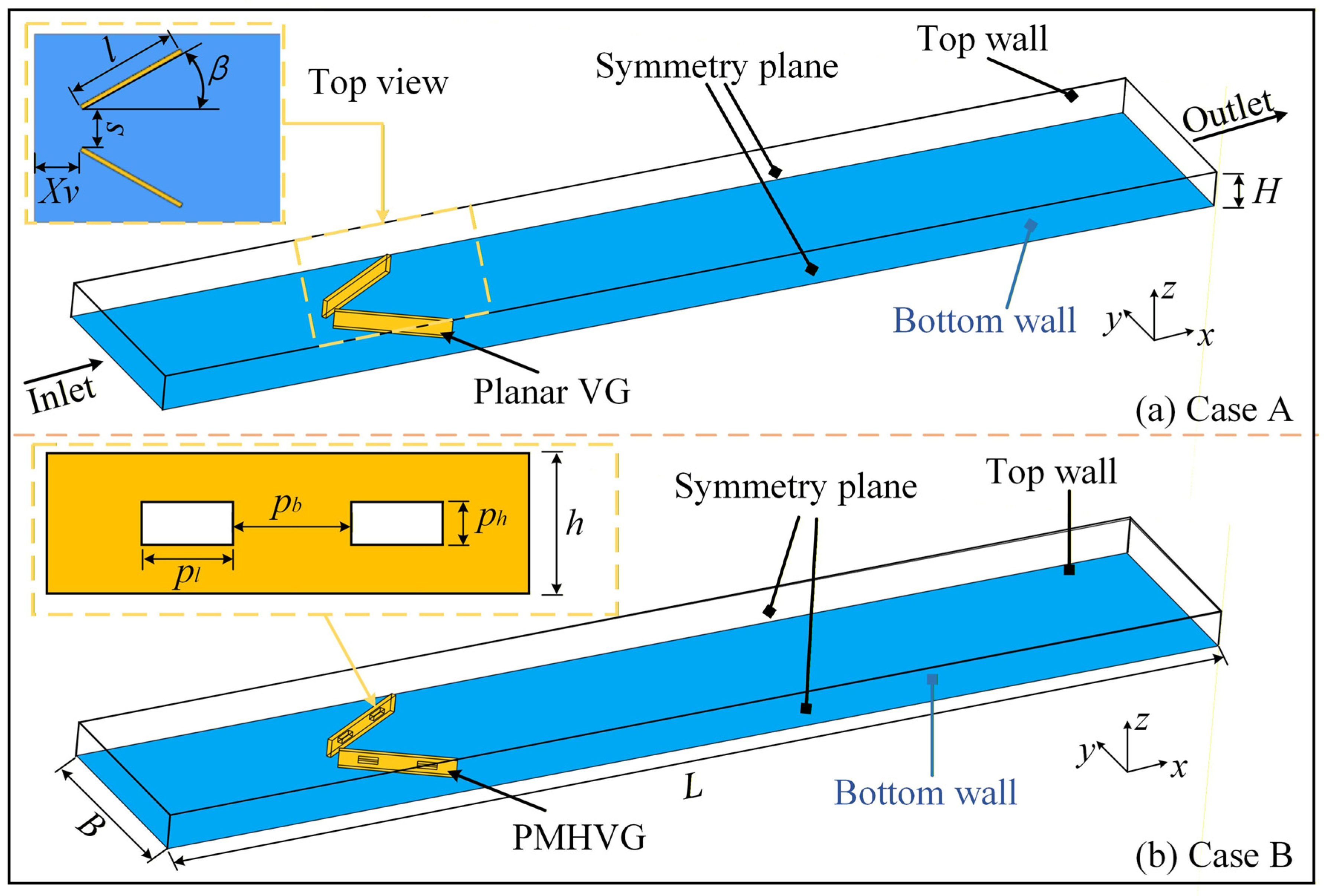
In this work, not only is the enhancement of heat-transfer performance achieved by PMHVGs examined, but the generation and interference behaviors of mixed coherent structures induced by PMHVGs under laminar conditions are also investigated. Considering that various external factors may influence vortex formation in practical applications, the selection of an appropriate VG configuration is essential for minimizing uncertainties arising from these factors. Therefore, in this study, the configuration was selected following methodologies reported in the relevant literature. Experimental [34] and numerical [35] investigations were conducted on the chosen configuration to evaluate the induced vortex behavior and the corresponding heat transfer enhancement and flow behavior effects, as illustrated in Figure 1. Detailed information on the selected models, including the non-punched VGs and the PMHVGs, is provided in Table 1.

2.2. Numerical Simulation

Numerical simulations were performed using a CFD package to investigate the heat transfer and flow characteristics induced by inserts, including both planar VGs and PMHVGs, within the channel. The flow was assumed to be steady, incompressible, and laminar, and the thermophysical properties of air were considered constant. The effects of viscous dissipation and gravitational forces were neglected. A symmetry boundary condition was applied, where zero normal velocity and zero gradients of all scalar quantities and tangential velocity components were imposed.
The governing equations are presented below:
Continuity equation:
( ρ u i ) x i = 0
Momentum equation:
( ρ u i u k ) x i = x i μ u k x i p x k
Energy equation:
x i ( ρ u i c p T ) = x i λ T x i
The computational domain was discretized using an unstructured mesh, and a grid independence study was performed to ensure numerical accuracy. Boundary conditions are summarized in Table 2. At the inlet, a uniform velocity profile and constant temperature were specified. At the outlet, a pressure outlet condition with zero-gradient temperature was applied. All solid surfaces, including the VGs and channel walls, were treated as no-slip and isothermal conditions.
The simulations were conducted using the steady-state segregated flow solver in STAR-CCM+, with SIMPLE pressure–velocity coupling and a second-order upwind discretization scheme. The gradients were reconstructed using the least-squares cell-based method with the Venkatakrishnan limiter. Convergence criteria were residuals for continuity, momentum, and energy equations < 10−5, 10−5, and 10−8. Additionally, the average outlet temperature and pressure drop were monitored; relative changes below 10−5 were considered converged. The laminar flow model was applied (Re = 200–1800). The flow is modeled as laminar since the Re remains below the conventional laminar–turbulent transition threshold for internal flows.

2.3. Data Reduction

The characteristic length of this work is defined as:
D = 2 H
where D is the equivalent diameter of the channel (m).
The Re is calculated as:
R e = ρ u i n D / μ
where ρ and μ are the density and viscosity of the fluid, respectively, and u i n is the air velocity in the inlet section.
The N u is given by:
N u = h m D λ
where h m is the mean convective heat transfer coefficient, and λ is the thermal conductivity of the air.
Furthermore, the f is employed to analyze the flow resistance characteristics induced by the PMHVGs installed inside the heated tube, and it is expressed as:
f = 2 Δ p D L ρ u i n 2
where Δ p is the pressure drop across the inlet and outlet of the section (Pa), and L is the length of the test section (m).
The dimensionless number S e , proposed by Song et al. [36,37], is adeptly employed to precisely characterize the intensity of mixed vortices. Its specific calculation formula is as follows:
S e = ρ D 2 μ | w y v z |
where | w y v z | represents the absolute value of the streamwise vorticity magnitude.
Thermal enhancement factor ( T E F ):
T E F = N u / N u 0 f / f 0
where subscript 0 denotes the smooth case.
In this study, mixed coherent structures refer to the integrated vortex system observed in the flow field, where multiple types of vortical structures (including streamwise and transverse vortices) coexist and interact without explicit separation. Instead of distinguishing individual vortex types quantitatively, the present work treats the vortex field as a coupled system and focuses on its overall spatial organization and evolution characteristics. The Q-criterion (Q = 0.5 (||Ω||2 − ||S||2), Q > 0) is employed to visualize vortex-dominated regions, where rotation strength exceeds strain rate [38,39]. This provides a global representation of the coherent vortex system rather than a classification of individual vortex components.
As a result of flow instability, a fluid with longitudinal velocity components emerges, generating a mixed vortex flow comprising both longitudinal and transverse vortices, each with distinct heat transfer benefits. The parameter S e is introduced to represent the ratio of the inertial force to the viscous force induced by this secondary flow. By employing S e , the correlation between the strength of secondary flow and heat transfer can be quantitatively characterized. This provides profound insight into the fundamental mechanisms that facilitate the enhancement of heat transfer rates via mixed vortex flows. Consequently, this paper will utilize S e as a tool to systematically analyze and demonstrate the inherent mechanisms of vortex-induced heat transfer enhancement under various circumstances.

2.4. Mesh Independence Test

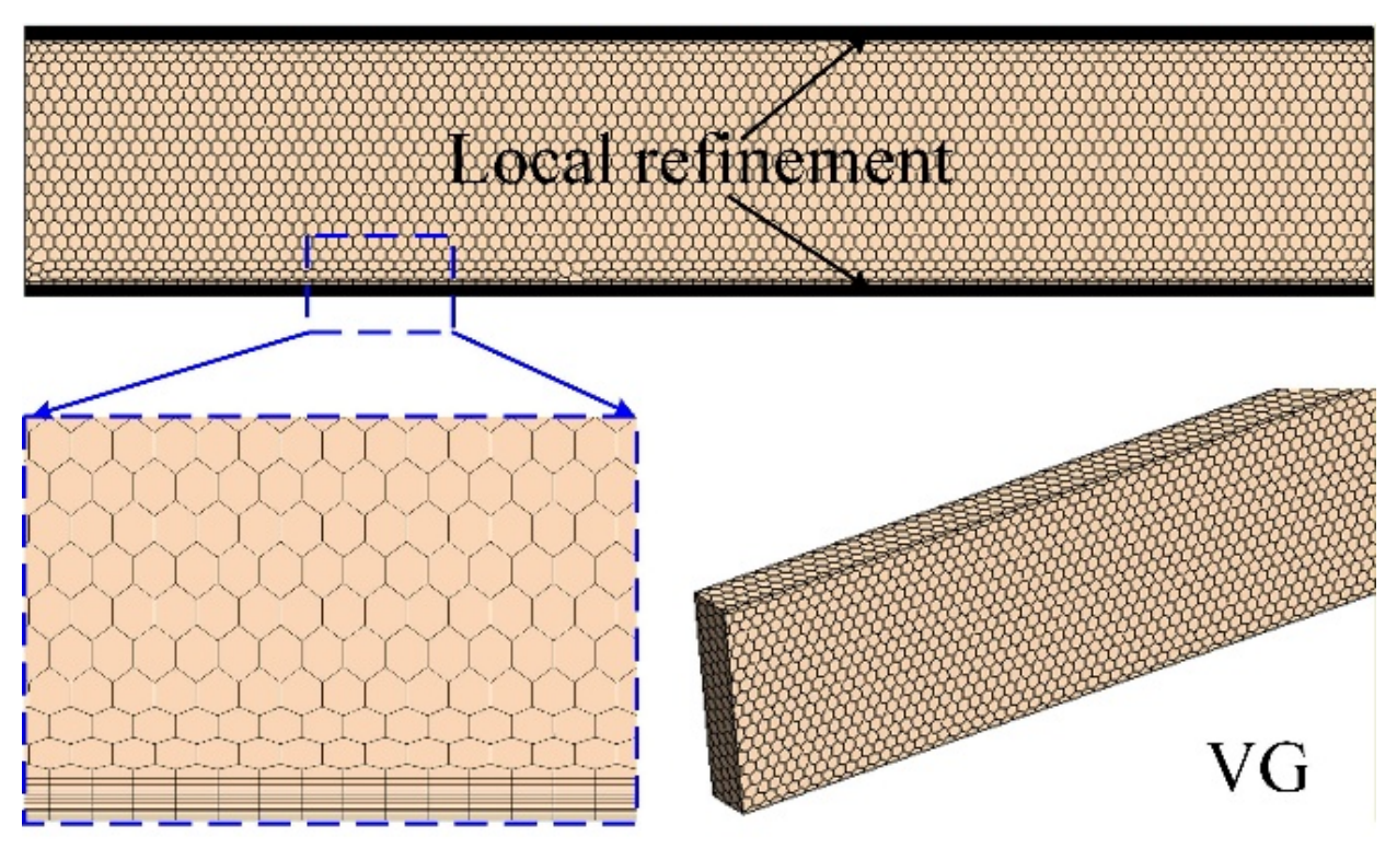
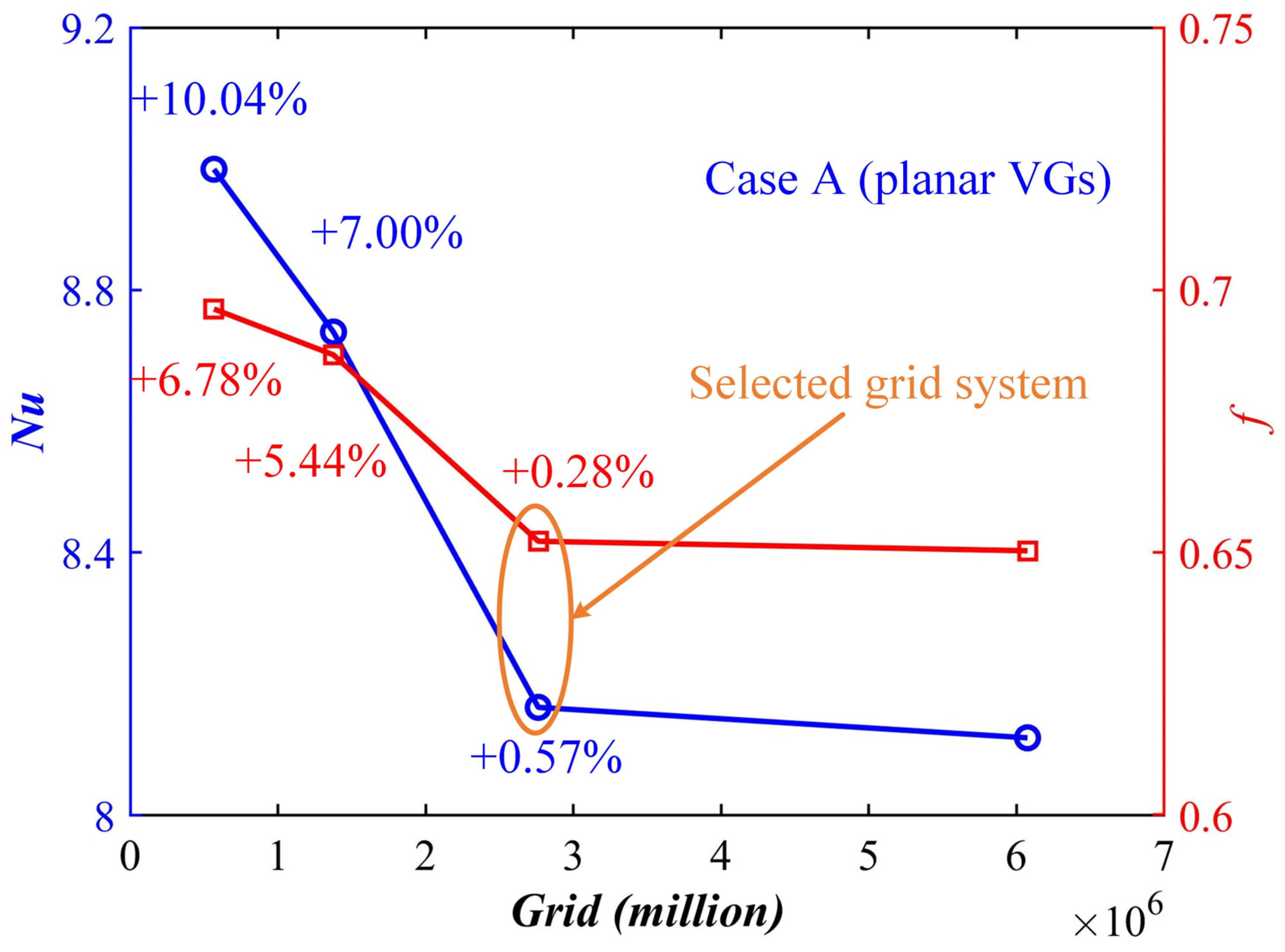
The computational mesh employed in this study is illustrated in Figure 2. To accurately resolve the near-wall flow and thermal boundary layers, prism-layer inflation and local mesh refinement were applied near the solid walls and VG surfaces. Four mesh systems with different resolutions were generated, consisting of 567,093, 1,376,204, 2,762,322, and 6,074,054 cells, respectively. A mesh independence study was conducted using the Nu and f as evaluation parameters.
The variations in Nu and f for different mesh densities are presented in Figure 3. Taking the third mesh system as the reference, the deviations of Nu and f obtained using the first mesh were 10.04% and 6.78%, respectively, while those obtained using the second mesh were 7.00% and 5.44%, respectively (Figure 3). When the mesh was further refined from 2,762,322 to 6,074,054 cells, the variations in Nu and f decreased to only 0.57% and 0.28%, respectively, indicating that the numerical solution had reached the asymptotic grid-convergence region.
To further quantify numerical uncertainty, a Grid Convergence Index (GCI) analysis based on Richardson extrapolation was performed using the three finest meshes. The corresponding formulation and procedure are provided in the revised manuscript. The obtained GCI values for the selected mesh are 0.62% for Nu and 0.31% for f, confirming that discretization uncertainty is negligible. Considering both numerical accuracy and computational cost, the mesh with 2,762,322 cells was selected for all subsequent simulations.

2.5. Numerical Uncertainty and Sources of Error

The principal numerical uncertainties originate from mesh discretization, convergence tolerance, discretization schemes, and the steady laminar assumption. Mesh-induced uncertainty was evaluated using the Grid Convergence Index (GCI). The convergence criterion for all governing equations was set to 10−6. Additional uncertainties associated with transient flow behavior and transition effects are discussed in the Limitations section.

3. Results and Discussion

3.1. Validation

To assess the reliability of the numerical model, a benchmark consistency validation is performed by comparing the present numerical results with those reported in Ref. [35], which provides numerical data for a geometrically identical VGs configuration at a representative Re number. Due to the absence of available data covering the full Re range for identical configurations in the literature, the validation is limited to this representative operating condition. The comparison shows good agreement in Nu (see Table 3), indicating that the present model is capable of accurately capturing (only 0.67%) the thermo-hydraulic characteristics of VG-induced flows.

3.2. Differences in Heat Transfer with and Without Holes

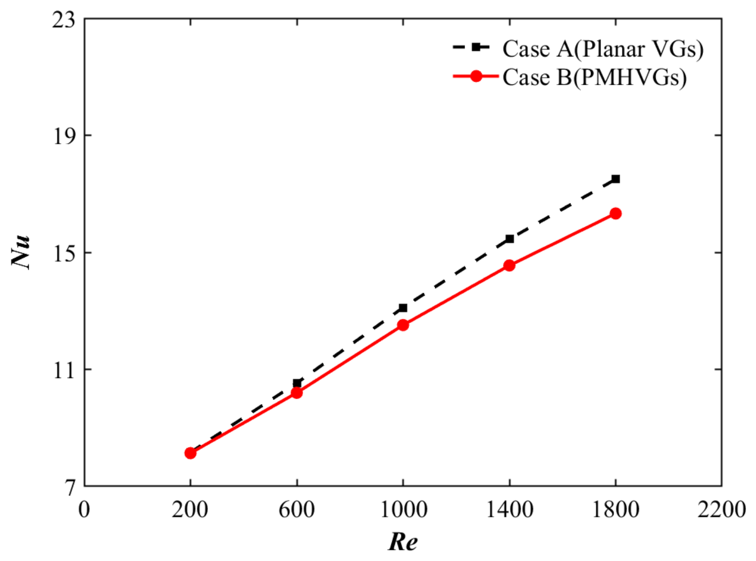
Figure 4 illustrates the variation in the space-averaged Nu as a function of the Re. Specifically, the plain VG (Case A) consistently outperforms the PMHVG (Case B) across the entire investigated laminar regime. At Re = 200, the Nu of Case A is higher by merely 0.32%, but this thermal deficit widens progressively at higher Re. This overall heat transfer degradation is fundamentally driven by the perforation-induced bleed flow, which passes through the PMHVG holes and directly weakens and disturbs the main longitudinal vortices. Within the laminar regime, these small-scale bleed flows fail to trigger turbulence but severely compromise the roll-up strength and structural sustainability of the mixed coherent structures.
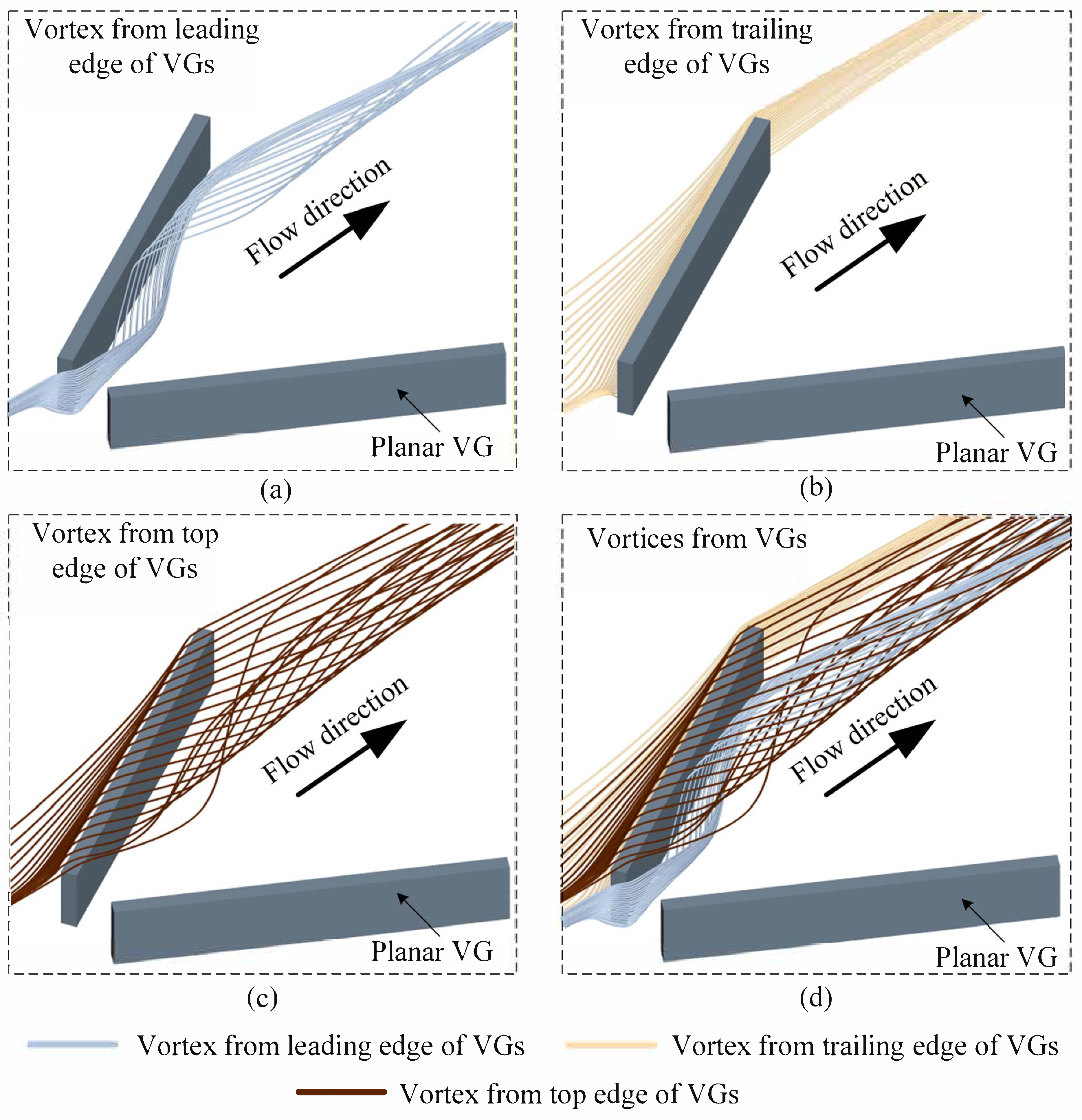
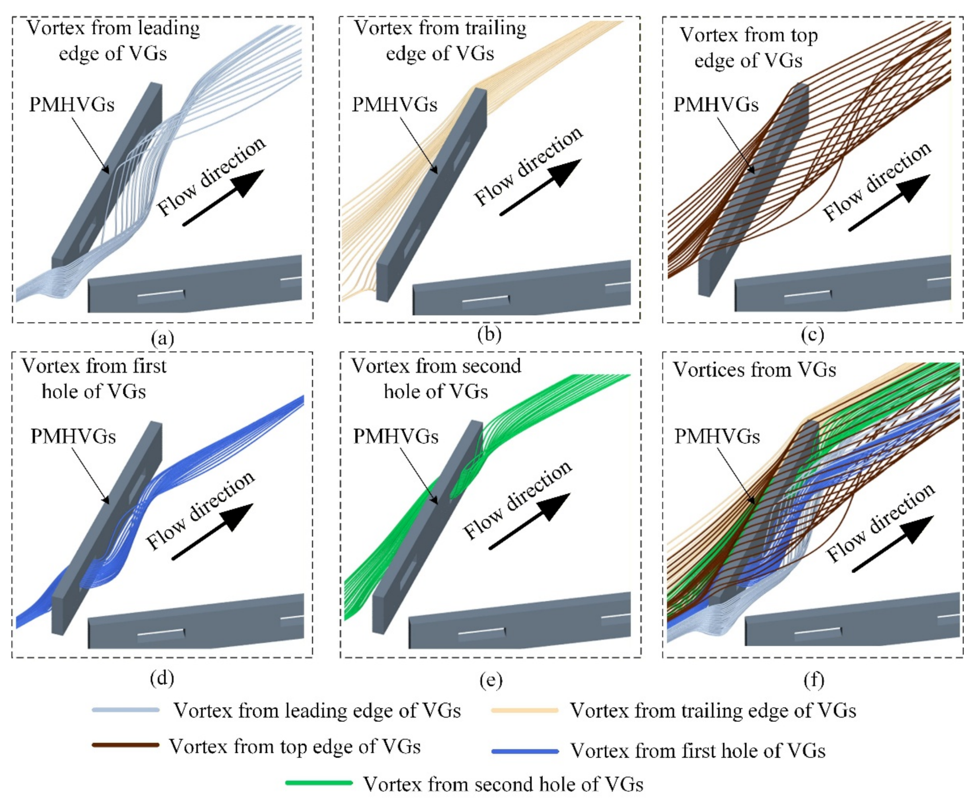
To further investigate the underlying fluid physics of this thermal disparity between the cases, Figure 5 and Figure 6 present the local streamline distributions for the two cases (Re = 200). When the fluid flows past the VGs, due to the development of the adverse pressure gradient, the fluid separates from the bottom surface and subsequently triggers three-dimensional flow separation in the vicinity of the VG. As a result, vortices were formed and encircled the VG in the form of mixed vortical flows. As shown in Figure 5a–c, the fluid rolls up from the leading edge, trailing edge, and top edge of the VG, forming vortices known as longitudinal vortices. The axes of rotation of these longitudinal vortices are parallel to the flow direction, and they move along with the fluid. The vortices induced at different VG locations exhibit distinct characteristics. Specifically, the vortex generated at the leading edge of the VG (Figure 5a) develops a ejecting into the recirculation zone downstream of the VG. After sweeping through the recirculation region, it merges into the main flow and propagates downstream. The vortex generated at the trailing edge of the VG (Figure 5b) does not immediately form large-scale high-intensity vortices but instead develops directly downstream. The vortex generated at the top of the VG (Figure 5c) initially rolls inward from the top toward the rear side of the VG. A portion of this vortex is attracted by the vortex originating from the leading edge, resulting in secondary inward rolling (Figure 5a). As shown in Figure 5d, the main vortices induced by the VG interact with each other, collectively governing the local transport of thermal energy within the fluid. In contrast, the fluid flow through case B exhibits different flow patterns. The streamline of the fluid flowing through the leading edge (Figure 6a) shows local weakening, while the changes in the fluid flowing through the trailing edge (Figure 6b) and top edge (Figure 6c) are not significant. When the fluid flows through the hole, it forms a local vortex by passing through the leading edge hole (Figure 6d), and after passing through the hole near the trailing edge (Figure 6e), it directly merges with the mainstream and flows downstream together. The mixing diagram is shown in Figure 6f.
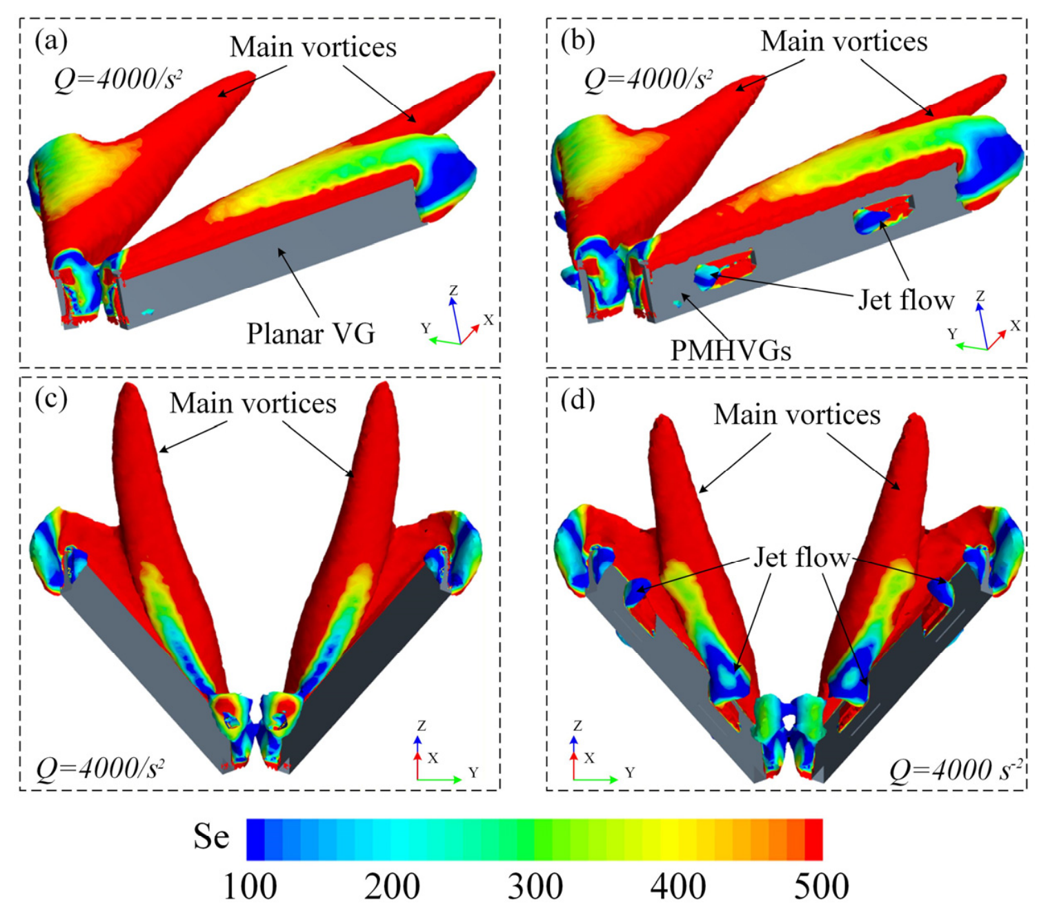
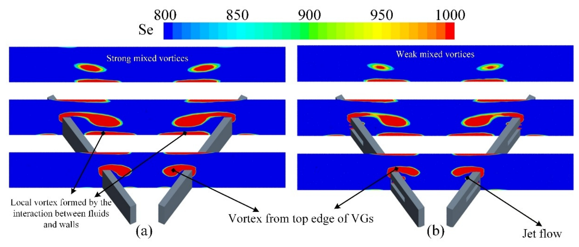
Figure 7 illustrates the intensity distributions of vortices induced by VGs in Cases A and B, where red indicates higher intensity. Overall, the mixed vortices induced by the non-punched VG exhibit greater intensity and extend farther downstream (Figure 7a,c, with a larger red area). Specifically, Compared to case A (see Figure 7b), the presence of holes alters the local pressure in the regions upstream and downstream of the VG. Consequently, in Figure 7c, the red regions display local discontinuities, indicating weakened vortex intensity and changes in the effective area of vortex influence.
Figure 7 illustrates the intensity distributions of vortices induced by VGs in Cases A and B, where red indicates higher intensity. Overall, the mixed vortices induced by the non-punched VG exhibit greater intensity and extend farther downstream (Figure 8a, with a larger red area). Specifically, the presence of holes alters the local pressure in the regions upstream and downstream of the VG. Consequently, in Figure 8b, the red regions display local discontinuities, indicating weakened vortex intensity and changes in the effective area of vortex influence.
As shown in Figure 8, the spatial distribution of se reveals distinct vortex interaction characteristics between planar and punched cases. In the planar case (Figure 8a), the vortex structures generated by the interaction of vortices exhibit significant coupling and mutual enhancement. This leads to the formation of continuous high Se regions, indicating enhanced coherent motion and momentum exchange. In contrast, the perforated case (Figure 8b) shows a more fragmented Se distribution, which is due to the weakened strength of other mixed eddies caused by the fluid formed by the perforation, resulting in a decrease in Se intensity.
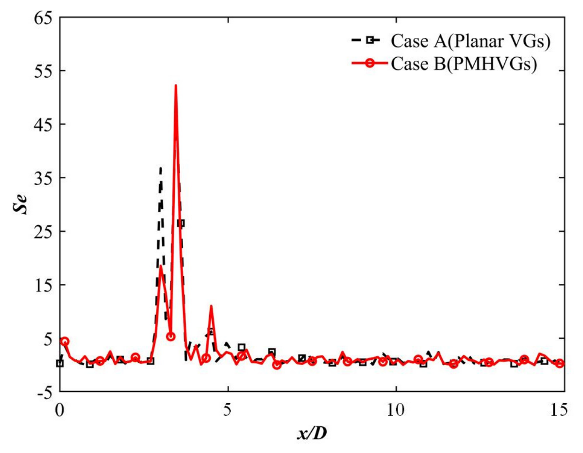
Figure 9 illustrates the streamwise distribution of the cross-sectional Se for both configurations at Re = 200. At the leading edge (x/D = 3), the Se value of Case A is significantly higher than that of Case B, representing a 98.2% increment. This indicates that the presence of perforations induces a pressure-relief effect on the windward face, which redirects part of the flow through the perforations and suppresses the initial vortex roll-up. Crucially, a distinct inversion occurs within the perforation bleed flow zone (x/D = 3.5), where Case B exhibits a noticeable enhancement, exceeding Case A by 7.8%. This local intensification is dynamically driven by the high-velocity perforation bleed flow, which generates intense localized shear and secondary mixing around the holes. Further downstream in the wake recirculation zone (x/D = 4.5), Case B maintains a higher local Se value with a 76.2% relative elevation compared to Case A, indicating that the base-bleeding action of the perforation bleed flows injects momentum into the low-pressure dead wake region. Nevertheless, this downstream recovery remains strictly localized and is insufficient to compensate for the massive attenuation of the primary longitudinal vortices at the leading edge.
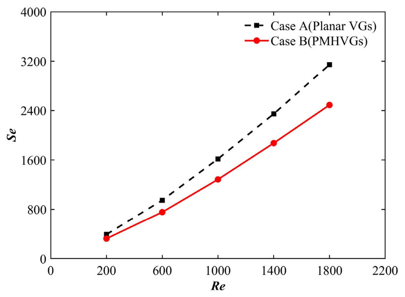
Figure 10 illustrates the variation in the volume-averaged Se with Re for Case A and Case B. For all investigated Re, the Se values of Case A remain consistently higher than those of Case B, indicating that the introduction of perforations weakens the overall secondary-flow intensity. This reduction is attributed to the redistribution of fluid momentum through the perforations, which partially dissipates the primary longitudinal vortices and consequently reduces the strength of the coherent secondary-flow structures.
Furthermore, the difference in Se between the two configurations increases with Re number, indicating that the influence of the perforation-induced bleed flow becomes increasingly pronounced as the flow rate increases. At relatively low Re, the bleed flow generated by the perforations is gradually damped by viscous effects, resulting in only a moderate attenuation of the secondary flow. As the Re increases, the stronger inertial effects intensify the momentum exchange through the perforations, leading to a more significant redistribution of the mainstream momentum. Consequently, the primary longitudinal vortices are weakened to a greater extent, causing a larger reduction in secondary-flow intensity compared with the planar VG. As a result, the difference in Se between the two configurations becomes progressively larger with increasing Re. These results demonstrate that the perforation-induced bleed flow modifies the evolution of the secondary flow rather than simply enhancing or suppressing it.
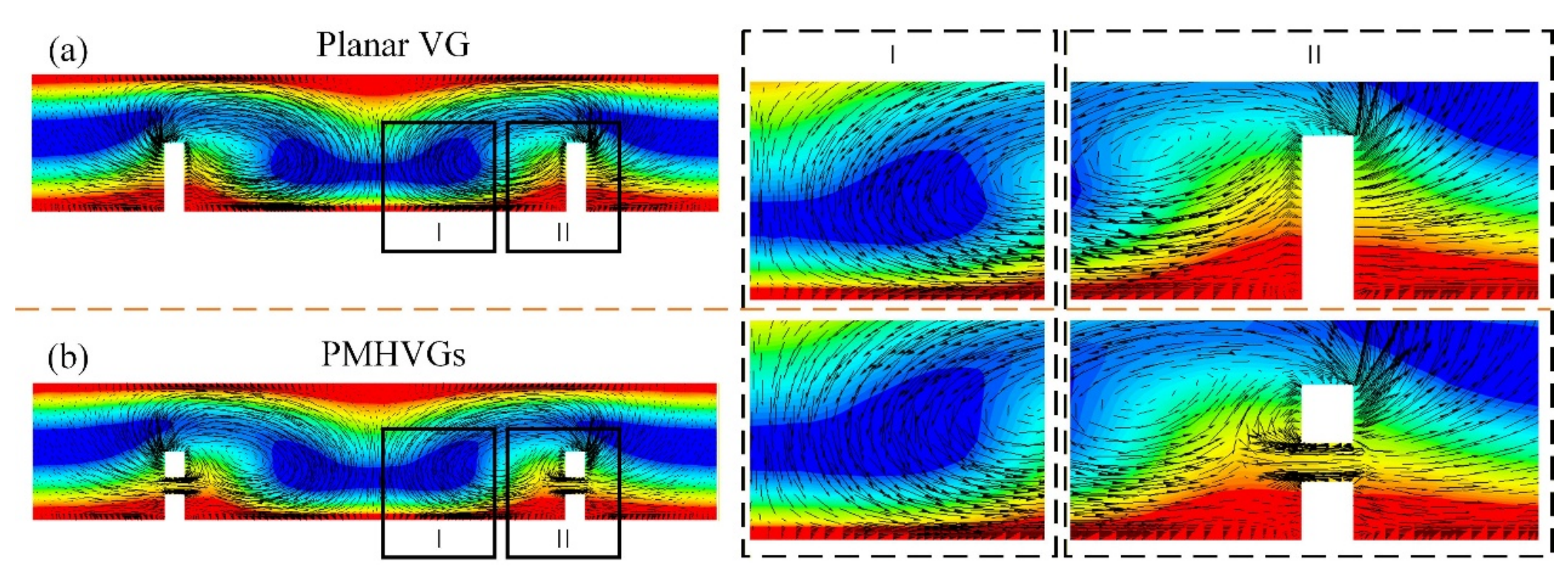
Figure 11 presents the velocity vector fields and temperature contour maps for the different cases. Based on a comparative analysis, two distinct regions were selected for decomposition and examination of vortex motion and temperature distribution. In Figure 11a (I), owing to the strong vortex induced at the top of the VG (Figure 7a and Figure 8a), the throw up and sweep motions of the mixed vortex enhance the mixing efficiency of fluids with temperature gradients inside the heat transfer tube. This is manifested in the figure as the low-temperature region extending away from the VG. In contrast, in Figure 11b (I), the vortex induced at the top of the VG is weaker (Figure 7c and Figure 8b), resulting in less intense near-wall ejection and sweep motions of the mixed vortex over a smaller area. Consequently, the mixing efficiency of the fluid with temperature gradients is reduced, and the low-temperature region shifts toward the VG, indicating a relatively weak control of the thermal boundary layer by the mixed vortex in this case.
In Figure 11a (II), the mixing efficiency of fluid with temperature gradients is similarly enhanced due to the strong vortex induced at the top of the VG. However, because this region is located within the VG’s recirculation zone and the downstream intensity of the mixed vortex is limited, the thermal boundary layer thickness remains relatively high. By contrast, in Figure 11b (II), the bleed flow generated by the perforations regulates the recirculation zone, redistributing heat on both sides of the VG. As a result, part of the heat from the outer side of the VG is transported into the inner side, leading to a more uniform fluid temperature distribution and a reduction in temperature gradients.

3.3. Differences in Pressure with and Without Holes

In this section, the flow characteristics in the different cases are discussed. The presence of perforations in the VGs locally alters the fluid pressure distribution, and this variation is related to factors such as the Re and the number of VGs. In the present study, with Re = 200–1800 and two VGs installed in the heat exchange tube, such minor variations are predictable.
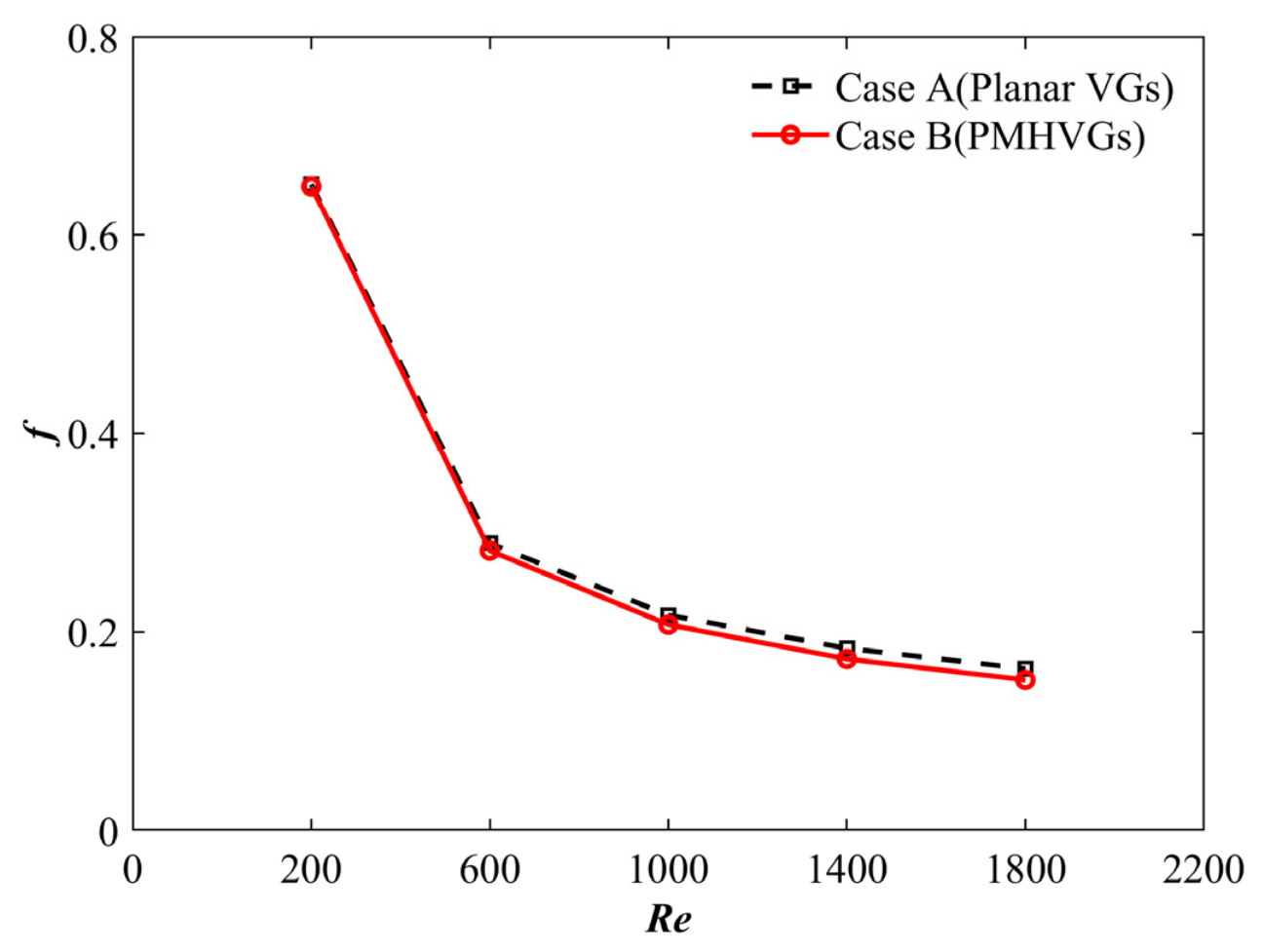
Figure 12 displays the f against Re for both cases. At Re = 200, the f value of Case A exceeds that of Case B by approximately 0.36%, a hydraulic advantage maintained up to Re = 1800. This friction mitigation is directly attributed to the form drag reduction achieved by the perforations. While the solid plate in Case A creates a large stagnation zone and an adverse low-pressure recirculation bubble, the multi-holes in Case B serve as passive bypasses. Fluid bleeding through these perforations suppresses flow separation and shrinks the dead recirculation zone, effectively minimizing macro-form drag under laminar constraints.
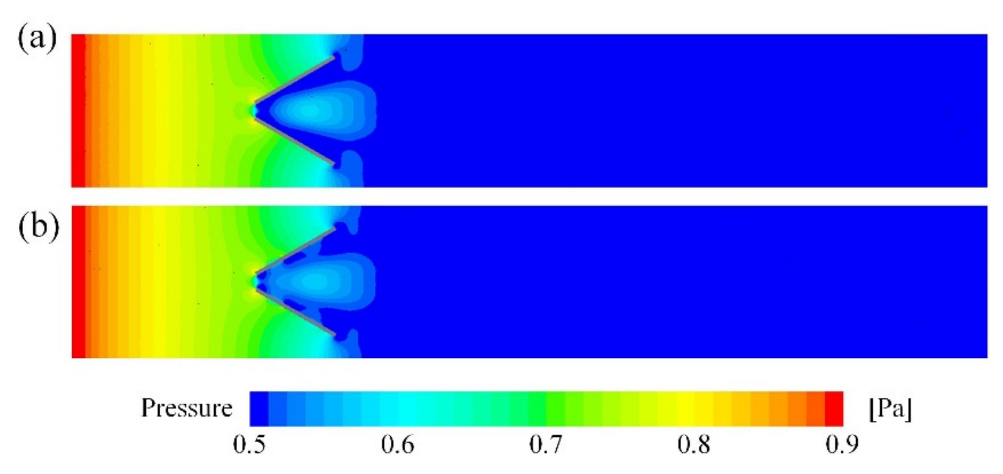
As shown in Figure 13, when the fluid passes through the VG, the presence of the VG induces significant local pressure variations. Specifically, a high-pressure region forms upstream of the VG, while a low-pressure region develops downstream. In the vicinity of the VG, the pressure exhibits relatively large fluctuations, which lead to the formation of mixed vortices. Downstream of the VG, the high-pressure region (yellow area) is relatively small, as the perforations on the VG reduce the pressure gradient between its upstream and downstream sides. In the present model, the local pressure characteristics near the VG remain pronounced for both cases, whereas the variations become negligible in regions far from the VG.
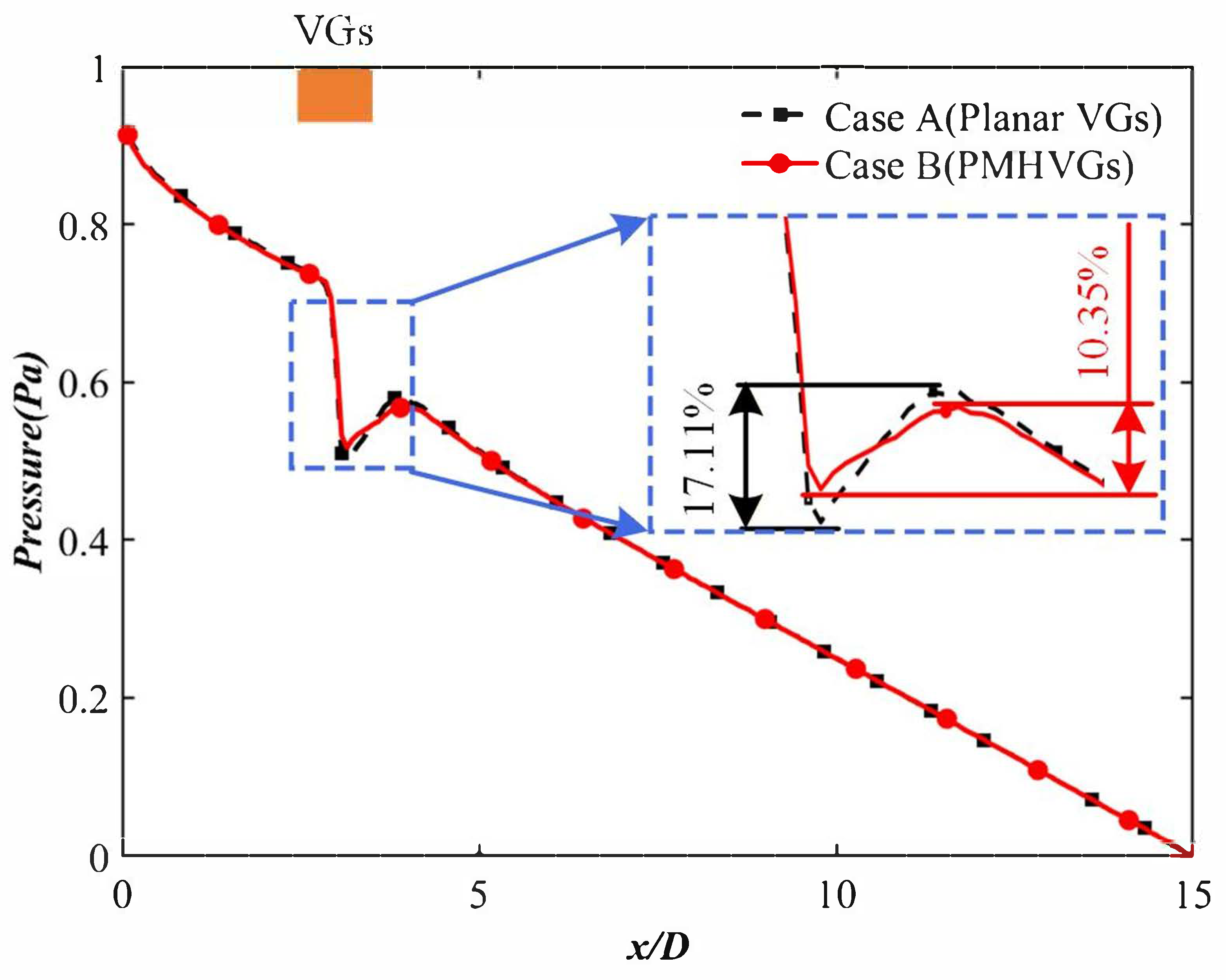
Figure 14 presents the pressure variation curves for the two cases, extracted along the centerline of the computational domain. In Case A, the local pressure upstream and downstream of the VG decreases by 17.11%, whereas in Case B, the corresponding change is 10.35%. This difference is attributed to the presence of holes in the VG.

3.4. Comprehensive Performance Evaluation

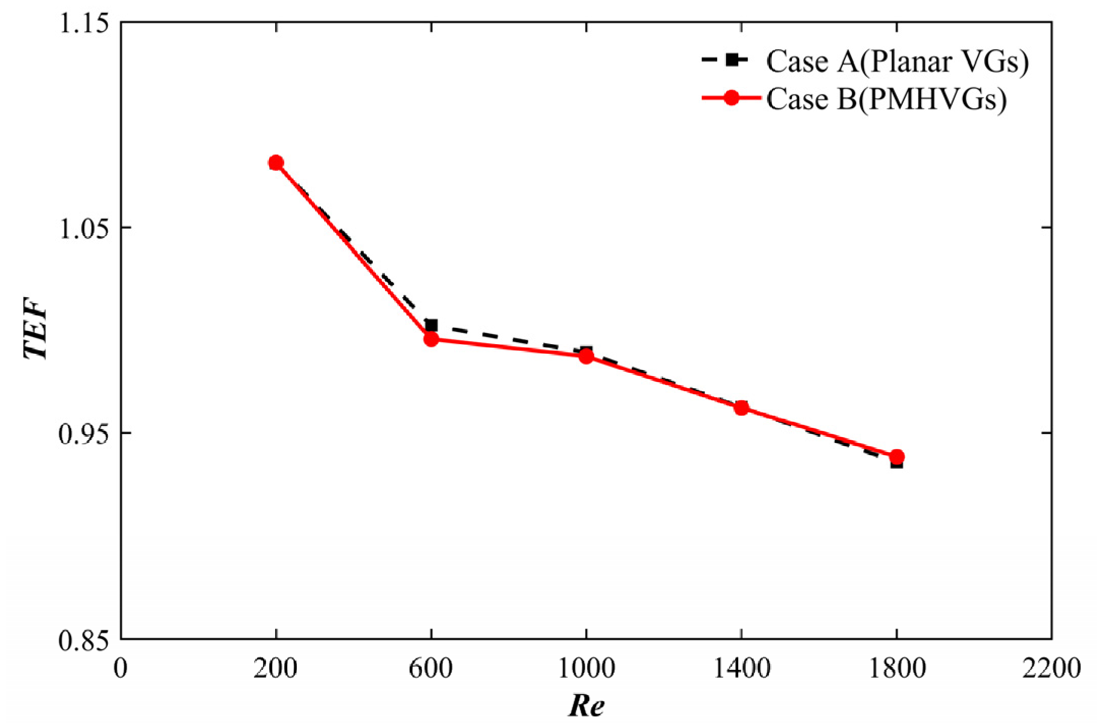
Figure 15 depicts the variations in TEF for both the plain VG (Case A) and the PMHVG (Case B) relative to the smooth channel baseline across the investigated Re range (Re = 200–1800). It can be observed that some configurations achieve a TEF greater than 1.0, with values spanning from 0.91 to 1.08 for Case A and from 0.92 to 1.08 for Case B, demonstrating a clear benefit in thermohydraulic performance over the smooth channel at Re < 600. Under the present geometric configuration, the TEF of the perforated VG is strongly dependent on Re. Compared with the non-perforated case, the perforated configuration yields superior TEF performance in the low Re regime (Re < 200) and in the high Re regime (Re > 1500), while no consistent advantage is observed in the intermediate range.

4. Conclusions

To clarify the influence mechanism of multi-hole perforations on VG-induced heat transfer enhancement, the flow and thermal characteristics of perforated VGs were numerically investigated over a laminar Re number range of Re = 200–1800. The evolution of mixed coherent structures and their interaction mechanisms were analyzed in detail. The main conclusions are summarized as follows:
1. Over the investigated Re range (Re = 200–1800), the introduction of perforations leads to a consistent reduction in flow resistance while maintaining comparable heat transfer performance. As a result, the overall thermo-hydraulic performance is improved, particularly in the high-Re regime.
2. The perforations modify the flow physics by introducing localized pressure-relief regions and viscosity-dominated bleed flows through the holes. These flows interact with the primary longitudinal vortices, leading to a redistribution of streamwise vorticity and a modification of vortex circulation and evolution of the coherent structures under laminar conditions.
3. The modified mixed coherent structures enhance near-wall sweep and ejection motions through laminar shear-driven interaction between bleed flow and vortical structures, which continuously disrupts the thermal boundary layer and promotes heat transport from the wall to the core region.
4. The present findings suggest that introducing controlled perforations in VGs can serve as an effective strategy to balance heat transfer enhancement and pressure loss reduction, providing useful guidance for the design of thermal management systems.

5. Limitations and Future Work

The potential early transition induced by VGs is not considered in the present study and is left for future work. The following remarks clarify the applicability and limitations of the present numerical model:
1. The present study employs a steady laminar-flow model to reveal the fundamental mechanisms governing perforation-induced pressure redistribution, vortex evolution, and heat transfer. The steady laminar assumption is considered appropriate for the present low-disturbance computational configuration. The steady nature of the solution is confirmed by the convergence of residuals and the stability of the flow and thermal fields.
2. The numerical uncertainty associated with mesh discretization has been quantified using the GCI. Additional uncertainties may arise from the steady-flow assumption and numerical modeling simplifications. These uncertainties are expected to remain within acceptable limits for comparative analysis.
3. Only one representative multi-hole vortex-generator configuration is considered in this study to isolate the underlying physical mechanisms. The effects of geometric parameters, including hole diameter, hole number, perforation arrangement, and attack angle, are beyond the scope of the present work. This approach ensures that the observed performance differences can be exclusively attributed to the presence of perforation, without interference from additional geometric coupling effects.
4. The present methodology can be extended to other VG geometries and operating conditions. Future investigations will focus on transient simulations, geometric optimization, and machine-learning-assisted surrogate models to further improve the thermo-hydraulic performance of perforated VGs, thereby enhancing the generality and predictive capability of the proposed framework.

Author Contributions

Conceptualization, J.W.; Methodology, K.L. and J.W.; Formal analysis, J.W.; Data curation, K.L. and J.W.; Writing—review & editing, K.L.; Visualization, K.L.; Funding acquisition, J.W. All authors have read and agreed to the published version of the manuscript.

Funding

This research was financially supported by the Youth Project of Hubei Provincial Natural Science Foundation (No. 2025AFB030) and the National Natural Science Foundation of China (Grant No. 52505274).

Data Availability Statement

The data presented in this study are available on request from the corresponding author.

Conflicts of Interest

The authors declare no conflicts of interest or state.

Nomenclature

BWidth of the test section, mm
DHydraulic diameter, m
f Friction factor
GCIGrid convergence index
HHeight of the test section, mm
hHeight of VGs, mm
h m heat transfer coefficient, W/(m2·K)
LLength of the channel, mm
lLength of VGs, mm
N u Nusselt number
p Pressure drop, Pa
p l Length of holes, mm
p b Distance between holes, mm
p h Height of holes, mm
PMHVGsVortex generators punched with multi-holes
R e Reynolds number
sDistance between VG, mm
S e Secondary flow intensity
SSTShear stress transport
T E F Thermal enhancement factor
uVelocity of the fluid, m s−1
VGsVortex generators
x, y, zCartesian coordinates
X v VG distance from entrance, mm
Greek symbols 
ρ Fluid density, Kg m 3
β Attack angles, °
λ Thermal conductivity, W m 1 K 1
ν Kinematic viscosity, m2 s−1
Subscripts 
oSmooth tube
inInlet of the channel
outOutlet of the channel
wWall

References

  1. Ismail, M.; Ali, A.M.; Pereira, S.-C.C. Vortex generators in heat sinks: Design, optimisation, applications and future trends. Results Eng. 2025, 25, 104216. [Google Scholar] [CrossRef]
  2. Zheng, N.; Zhang, K.; Chen, Q.; Sun, Z. Novel self-join winglet vortex generators for enhanced heat transfer of turbulent airflow in round tubes. Int. Commun. Heat Mass Transf. 2022, 130, 105806. [Google Scholar] [CrossRef]
  3. Wu, X.; Fu, T.; Wang, J.; Zeng, L.; Zhang, F. A comparative study of fluid flow and heat transfer in the tube with multi-v-winglets vortex generators. Appl. Therm. Eng. 2024, 236, 121448. [Google Scholar]
  4. Promvonge, P.; Sripattanapipat, S.; Thianpong, C.; Skullong, S.; Promthaisong, P.; Nakhchi, M.E. Enhanced thermal effectiveness of square duct with v-type double-baffles: Numerical study. Int. Commun. Heat Mass Transf. 2024, 157, 107727. [Google Scholar]
  5. Feng, J.J.; Teh, C.P.; Ng, K.C.; Jen-Haw, J.C.; Xiao, D.; Abakr, Y.A.; Chan, A.; Chen, B. Heat transfer and fluid flow analysis in circular tubes with multi-delta-winglets vortex generators. Int. Commun. Heat Mass Transf. 2024, 159, 108267. [Google Scholar]
  6. Younes, E.; Hamidouche, S.; Gautier, R.; Russeil, S. Spectral analysis of the transition to turbulence downstream a delta winglet pair vortex generator in an airflow channel. Phys. Fluids 2023, 35, 014108. [Google Scholar] [CrossRef]
  7. Karkaba, H.; Russeil, S.; Simo Tala, J.V.; Bougeard, D.; Boonaert, J.; Etienne, L.; Pelay, U.; Lecoeuche, S. Effect of using multiple vortex generator rows on heat transfer enhancement inside an asymmetrically heated rectangular channel. Appl. Therm. Eng. 2023, 227, 120359. [Google Scholar] [CrossRef]
  8. Ekrani, S.M.; Ganjehzadeh, S.; Esfahani, J.A. Multi-objective optimization of a tubular heat exchanger enhanced with delta winglet vortex generator and nanofluid using a hybrid cfd-svr method. Int. J. Therm. Sci. 2023, 186, 108141. [Google Scholar]
  9. Wu, J.; Liu, P.; Yu, M.; Liu, Z.; Liu, W. Thermo-hydraulic performance and exergy analysis of a fin-and-tube heat exchanger with sinusoidal wavy winglet type vortex generators. Int. J. Therm. Sci. 2022, 172, 107274. [Google Scholar]
  10. Min, C.; Li, H.; Gao, X.; Wang, K.; Xie, L. Numerical investigation of convective heat transfer enhancement by a combination of vortex generator and in-tube inserts. Int. Commun. Heat Mass Transf. 2021, 127, 105490. [Google Scholar] [CrossRef]
  11. Zhou, G.; Feng, Z. Experimental investigations of heat transfer enhancement by plane and curved winglet type vortex generators with punched holes. Int. J. Therm. Sci. 2014, 78, 26–35. [Google Scholar] [CrossRef]
  12. Gupta, A.; Roy, A.; Gupta, S.; Gupta, M. Numerical investigation towards implementation of punched winglet as vortex generator for performance improvement of a fin-and-tube heat exchanger. Int. J. Heat Mass Transf. 2020, 149, 119171. [Google Scholar]
  13. Syaiful; Nabilah, H.; Suryo Utomo, M.S.K.T.; Suprihanto, A.; Soetanto, M.F. Numerical simulation of heat transfer enhancement from tubes surface to airflow using concave delta winglet vortex generators. Results Eng. 2022, 16, 100710. [Google Scholar] [CrossRef]
  14. Pérez, R.B.; Pérez, A.M.; Suárez, D.S. Influence of the punched holes on thermohydraulic performance and flow pattern of rectangular channels with a pair of perforated vortex generators. Int. J. Heat Mass Transf. 2022, 184, 122291. [Google Scholar] [CrossRef]
  15. Van Hap, N.; Nhan, P.T.; Hien, H.P.; Phu, N.M. Thermohydraulic performance augmentation in a solar air heater using a perforated circular segment vortex generator. Environ. Sci. Pollut. Res. Int. 2023, 30, 65338–65350. [Google Scholar] [CrossRef] [PubMed]
  16. Göksu, T.T.; Behçet, R. Experimental investigation of the effect of a novel curved winglet vortex generator on heat transfer with a designed controller circuit. Int. J. Therm. Sci. 2022, 180, 107724. [Google Scholar] [CrossRef]
  17. Wang, J.; Zeng, L.; Yu, S.; He, Y.; Tang, J. Experimental and numerical investigations of tube inserted with novel perforated rectangular v-shape vortex generators. Appl. Therm. Eng. 2024, 249, 123451. [Google Scholar] [CrossRef]
  18. Wang, J.; Li, C.; Zeng, L.; Fu, T.; Liu, K. Thermal performance analysis of a heat exchanger with a novel turbulator insert by using machine learning method. Case Stud. Therm. Eng. 2025, 73, 106412. [Google Scholar]
  19. Luo, L.; Wen, F.; Wang, L.; Sundén, B.; Wang, S. On the solar receiver thermal enhancement by using the dimple combined with delta winglet vortex generator. Appl. Therm. Eng. 2017, 111, 586–598. [Google Scholar] [CrossRef]
  20. Xu, Y.; Islam, M.D.; Kharoua, N. Numerical study of winglets vortex generator effects on thermal performance in a circular pipe. Int. J. Therm. Sci. 2017, 112, 304–317. [Google Scholar] [CrossRef]
  21. Sheikholeslami, M. Numerical investigation of solar system equipped with innovative turbulator and hybrid nanofluid. Sol. Energy Mater. Sol. Cells 2022, 243, 111786. [Google Scholar] [CrossRef]
  22. Huang, C.-H.; Liu, L.-W. Optimal position and perforated radius of punched vortex generators for heat sink. Case Stud. Therm. Eng. 2022, 32, 101916. [Google Scholar] [CrossRef]
  23. Saini, P.; Shah, M.P. Performance evaluation of finned tube heat exchanger using curved wavy delta winglet vortex generators with circular perforations. Int. Commun. Heat Mass Transf. 2024, 159, 108184. [Google Scholar] [CrossRef]
  24. Wang, Y.; Foo, J.-J.; Tran, M.-V.; Nair, S.R.; Oon, C.S. Numerical investigation of thermo-hydraulic performance of perforated rectangular and sinusoidal vortex generators in a double-pipe heat exchanger. J. Therm. Anal. Calorim. 2024, 149, 11137–11154. [Google Scholar]
  25. Zhang, Y.; Zhang, P.; Wang, X.; Gong, B.; Zhang, L.J. Performance enhancement of punched holes streamlined winglet pair vortex generator for fin-and-tube heat exchanger. J. Mech. Sci. Technol. 2024, 38, 2613–2625. [Google Scholar]
  26. Promvonge, P.; Promthaisong, P.; Skullong, S. Numerical heat transfer in a solar air heater duct with punched delta-winglet vortex generators. Case Stud. Therm. Eng. 2021, 26, 101088. [Google Scholar] [CrossRef]
  27. Ali, S.; Dbouk, T.; Wang, G.; Wang, D.; Drikakis, D. Advancing thermal performance through vortex generators morphing. Sci. Rep. 2023, 13, 368. [Google Scholar] [CrossRef] [PubMed]
  28. Heriyani, O.; Djaeni, M.; Syaiful, S.; Putri, A.K. Perforated concave rectangular winglet pair vortex generators enhance the heat transfer of air flowing through heated tubes inside a channel. Results Eng. 2022, 16, 100705. [Google Scholar] [CrossRef]
  29. Promvonge, P.; Skullong, S. Thermohydraulic performance and entropy generation in heat exchanger tube with louvered winglet tapes. Int. J. Therm. Sci. 2022, 181, 107733. [Google Scholar] [CrossRef]
  30. Jayranaiwachira, N.; Promvonge, P.; Thianpong, C.; Skullong, S. Entropy generation and thermal performance of tubular heat exchanger fitted with louvered corner-curved v-baffles. Int. J. Heat Mass Transf. 2023, 201, 123638. [Google Scholar]
  31. Lertnuwat, B. Effect of the number and placement of punched holes in rectangular winglet vortex generators on solar air heater performance. Energy Convers. Manag. X 2024, 24, 100714. [Google Scholar] [CrossRef]
  32. Wang, J.; Zeng, L.; Ma, S.; Zhao, B.; Li, C. Entropy generation and thermal behavior analysis of tube fitted with multi-perforation vortex generators. Appl. Therm. Eng. 2025, 261, 125099. [Google Scholar]
  33. Ahmed, S.Y.; Al-Amir, Q.R.; Hamzah, H.K.; Ali, F.H.; Abed, A.M.; Al-Manea, A.; Egab, K.; Al-Rbaihat, R.; Saleh, K.; Alahmer, A. Part B: Fundamentals. Investigation of natural convection and entropy generation of non-newtonian flow in molten polymer-filled odd-shaped cavities using finite difference lattice boltzmann method. Numer. Heat Transf. Part B Fundam. 2025, 86, 2830–2855. [Google Scholar]
  34. Tiggelbeck, S.; Mitra, N.; Fiebig, M. Comparison of wing-type vortex generators for heat transfer enhancement in channel flows. J. Heat Transf. 1994, 116, 880–885. [Google Scholar] [CrossRef]
  35. Zhang, Q.; Wang, L.-B.; Zhang, Y.-H. The mechanism of heat transfer enhancement using longitudinal vortex generators in a laminar channel flow with uniform wall temperature. Int. J. Therm. Sci. 2017, 117, 26–43. [Google Scholar] [CrossRef]
  36. Song, K.; Tagawa, T.; Chen, Z.; Zhang, Q. Heat transfer characteristics of concave and convex curved vortex generators in the channel of plate heat exchanger under laminar flow. Int. J. Therm. Sci. 2019, 137, 215–228. [Google Scholar] [CrossRef]
  37. Song, K.; Hu, W.; Liu, S.; Wang, L. Quantitative relationship between secondary flow intensity and heat transfer intensity in flat-tube-and-fin air heat exchanger with vortex generators. Appl. Therm. Eng. 2016, 103, 1064–1070. [Google Scholar]
  38. Li, Z.; Zhang, X.; He, F. Evaluation of vortex criteria by virtue of the quadruple decomposition of velocity gradient tensor. arXiv 2024, arXiv:2406.02558. [Google Scholar]
  39. Kovacs, K.A.; Balla, E. Quantitative comparison of vortex identification methods in three-dimensional fluid flow around bluff bodies. Int. J. Heat Fluid Flow 2025, 113, 109773. [Google Scholar] [CrossRef]
Figure 1. Schematic view of the investigated model: (a) case A; (b) case B.
Processes 14 02217 g001
Figure 2. An unstructured mesh was generated in the computational domain.
Processes 14 02217 g002
Figure 3. Grid independence test of Case A.
Processes 14 02217 g003
Figure 4. Comparison of Nu values in two cases under different Re.
Processes 14 02217 g004
Figure 5. Schematic decomposition of local streamlines for the planar VG (case A).
Processes 14 02217 g005
Figure 6. Schematic decomposition of local streamlines for the perforated VG (case B).
Processes 14 02217 g006
Figure 7. Contour maps of vortex intensity for different vortex forms: (a) Se of Case A; (b) Se of Case B; (c) Bottom schematic diagram of Se of Case A; (d) Bottom schematic diagram of Se of Case B; (Q = 4000 s−2).
Processes 14 02217 g007
Figure 8. Contour maps of vortex intensity for different cases.
Processes 14 02217 g008
Figure 9. The streamwise distribution of the spanwise-averaged Se number.
Processes 14 02217 g009
Figure 10. Variation in the volume-averaged Se with Re for Case A and Case B.
Processes 14 02217 g010
Figure 11. Velocity vectors and temperature contours for different cases (a) Planar VG; (b) Punched VG.
Processes 14 02217 g011
Figure 12. Comparison of f values in two cases under different Re.
Processes 14 02217 g012
Figure 13. Pressure distribution contours for different cases (a) Planar VG; (b) Punched VG.
Processes 14 02217 g013
Figure 14. Pressure variation curves for different cases.
Processes 14 02217 g014
Figure 15. Comparison of TEF values in two cases under different Re.
Processes 14 02217 g015
Table 1. Details of the models.
ParameterValue (mm)ParameterValue
L 120 β 30°
B 20 X v 20   m m
H 4   p l 2   m m
s 0.8   p b 4   m m
l 12 p h 0.5   m m
h 2   
Table 2. Details of the boundary conditions.
Section (s)Boundary Conditions
Inlet u = u i n , v = w = 0 ,   T in   = 303.15   K
OutletPressure outlet. T x = 0
Bottom and top surfaces  u = v = w = 0 ,     T w = 353.15   K
Surface of VGsAdiabatic, no-slip
Table 3. Comparison of N u value obtained by our and other works.
N u Error
Present work8.160.67%
Zhang et al. [35]8.11
Disclaimer/Publisher’s Note: The statements, opinions and data contained in all publications are solely those of the individual author(s) and contributor(s) and not of MDPI and/or the editor(s). MDPI and/or the editor(s) disclaim responsibility for any injury to people or property resulting from any ideas, methods, instructions or products referred to in the content.