Article

Numerical Simulation and Field Testing of Coal Seam Drilling Hole Gas Discharge Characteristics Based on Fluid–Solid Interaction


1
College of Mining Engineering, Taiyuan University of Technology, Taiyuan 030024, China
2
Shanxi Xinyuan Coal Limited Liability Company, Jinzhong 046000, China
*
Author to whom correspondence should be addressed.
Processes 2026, 14(13), 2212; https://doi.org/10.3390/pr14132212
Submission received: 5 June 2026 / Revised: 18 June 2026 / Accepted: 20 June 2026 / Published: 7 July 2026
(This article belongs to the Topic Advances in Coal Mine Disaster Prevention Technology)

Abstract

The effectiveness of gas discharge depends on the geological conditions and drilling parameters. Investigating gas seepage behavior near boreholes under fluid–solid coupling conditions can provide theoretical support for scientifically determining the effective discharge radius (EDR) and ensuring mining safety. In this study, taking Xinyuan Coal Mine as the engineering background, a fluid–solid coupled model describing gas migration was developed. The effects of the discharge duration, borehole diameter, permeability, and borehole layout on the spatiotemporal evolution of gas around boreholes and EDR were investigated. The results indicate that gas pressure around the borehole continuously decreases with time, and the affected zone expands elliptically. The EDR exhibits a power-law relationship with time. Increasing the borehole diameter enlarges the EDR, with the effect being particularly significant in the initial stage of gas discharge. After 5 h of gas discharge, the EDR in high-permeability coal seams is approximately twice that in low-permeability coal seams. Compared to the triple-flower patterns, the square pattern produces a larger EDR at the same time. The EDR calculated based on the measured values of the drill cuttings volume S value and drill cuttings desorption gas volume K1 value shows a high degree of consistency with the simulation results. After 5 h of gas discharge using the square pattern, the gas volume fraction at the upper corner of the working face dropped to the safe level of 6%, enabling mining to resume.

1. Introduction

As a conventional fossil fuel, coal has played a pivotal role in China’s rapid economic and social development [1]. With the gradual depletion of shallow coal seam resources, mining activities have increasingly extended into deeper strata. The high temperature, pressure, and disturbance environments in deep mining zones significantly elevate the risk of coal–rock dynamic disasters [2]. To effectively curb accidents during coal mining operations, the Chinese government established, in 2019, the principle of “prioritizing regional comprehensive gas outburst prevention measures supplemented by local comprehensive measures,” based on a systematic review of historical accident data and lessons learned [3]. Since its implementation, both the frequency of mining disasters and the number of casualties have steadily declined, demonstrating the scientific rationale and practical effectiveness of this policy [4]. Among localized comprehensive outburst prevention strategies, borehole gas discharge technology has been widely adopted in coal mines because of its cost-effectiveness, high reliability, and strong adaptability [5].
Drilling gas discharge technology operates based on mechanisms such as negative pressure discharge and concentration gradient-driven flow [6]. This approach involves constructing specialized boreholes in coal seams to pre-extract the gas from within the seams, discharging it to the surface or underground treatment systems. The process achieves multiple objectives, including reducing the gas content and pressure in coal seams, mitigating outburst risks, and enabling the resource utilization of extracted gas [7,8]. A scientifically sound and well-planned drilling layout is crucial for improving the efficiency of gas discharge. Increasing both the borehole length and radius can enhance the coalbed methane discharge rates; however, this improvement does not always follow a stable trend [9,10,11]. When multiple boreholes are used for methane discharge, the interaction and disturbance effects between boreholes can expand the EDR and improve the overall discharge efficiency [12,13]. However, an excessively high borehole density may compromise coal structure integrity, thereby increasing the risk of dynamic disasters [14]. Owing to the extremely complex geological and mining conditions in coal mines, many existing theoretical approaches remain difficult to apply directly to precise field-scale disaster prevention and control [15].
The effective discharge radius (EDR) of boreholes, which is a crucial parameter for optimizing borehole layout, is defined as the distance from the borehole center to the point where the gas pressure in the coal seam decreases to the critical threshold required for safe production within a specified time frame [16]. Presently, the primary methods used for in situ determination of the borehole EDR include the gas pressure reduction, gas flow rate, and drill cuttings index methods [17,18,19]. Research indicates that coal and gas outburst are essentially destabilization processes resulting from the coupled interaction of multiple physical fields, including gas, geological stress, and coal properties [20]. However, the gas pressure reduction and gas flow rate methods capture changes in only a single parameter (gas pressure or flow rate), making it difficult to comprehensively characterize the integrated state of outburst hazards [21,22]. By contrast, the drill cuttings index method incorporates both the drill cuttings volume, which reflects stress distribution, and the gas desorption index of drill cuttings, which represents dynamic gas behavior [19]. This combined approach enables a more systematic reflection of the dynamic response associated with multi-field coupling in coal seams, from the perspective of the co-evolution of stress and gas fields. Moreover, compared with conventional methods for gas pressure or flow rate measurement, which typically require sophisticated equipment and prolonged testing periods, the determination of the S value and K1 value is considerably more convenient and efficient, making it more suitable for field application under underground mining conditions [23]. Consequently, it provides a more reliable approach for optimizing outburst prevention strategies.
Xinyuan Coal Mine, located in Shouyang County, Shanxi Province, is classified as a high-gas mine. To effectively prevent and control coal mine dynamic disasters, designing and optimizing advanced gas discharge borehole layouts based on the site-specific actual conditions is necessary. In this study, the working face of Xinyuan Coal Mine was selected as the engineering test site, and a fluid–solid coupled numerical model for gas discharge through coal seam boreholes was developed. The model was subsequently validated using field measurement data. Based on the validated model, the spatiotemporal evolution characteristics of gas during the discharge process were systematically analyzed. Additionally, the effects of the discharge duration, borehole radius, permeability, and borehole layout on the EDR were investigated. Finally, an efficient gas discharge strategy for Xinyuan Coal Mine was proposed.

2. Materials and Methods

2.1. Fluid–Solid Coupling Theory

Gas within coal seams migrates into boreholes through seepage and is ultimately discharged to surface or underground treatment systems, representing a typical gas–solid coupling process [24]. Based on seepage mechanics and fluid mechanics theories, the following assumptions are made in the simulation:
(1) The coal seam is treated as an isotropic medium. This study focuses on the gas seepage process during borehole gas emission and the negative feedback effect of effective stress on coal seam permeability. The process is primarily described using Darcy’s law and the effective stress equation; considering heterogeneity would make the derivation of the equations extremely complex.
(2) The coal seam is treated as a linear elastic medium. During coal seam gas extraction, the region around the borehole remains in a generally linear elastic state, and its stress–strain relationship can be expressed by the generalized Hooke’s law. An equivalent isotropic model provides a unified foundation for the subsequent incorporation of other physical field equations.
(3) The deformation of coal follows the small deformation theory. Changes in gas pressure around the borehole mainly cause the shrinkage or expansion of coal pores, with little or no large deformation involved.
(4) The adsorption/desorption of gas in the coal seam is an isothermal process. The temperature conditions at the coal mine working face are basically stable, and temperature changes caused by gas adsorption/desorption are almost negligible. This simplification also helps to focus on the core issues of fluid–solid coupling.

2.1.1. Control Equation for Coal Seam Deformation

The stress state of gas-bearing coal can be analyzed using the effective stress principle originally proposed by Terzaghi in soil mechanics, which can be expressed as follows [25]:
σ i j e = σ i j β f p f + β m p m δ i j
where σeij denotes the effective stress tensor, σij represents the original stress tensor, βf and βm are the effective stress coefficients, pf and pm denote the gas pressures in the coal fractures and coal matrix, respectively, and δij is the Kronecker delta function.
Coal is a porous medium composed of both a matrix and fractures network. According to elasticity theory, the deformation behavior of coal follows Hooke’s law, which can be expressed as follows [26,27]:
G u i , j j + G 1 2 ν u j , j i β f p f β m p m + F i = 0
where G represents the shear modulus, u denotes the deformation, υ is the Poisson’s ratio, and Fi is the external force acting at position i.

2.1.2. Control Equation for Gas Seepage

Gas in coal seams exists in both adsorbed and free states [28]. According to the law of mass conservation, the gas content per unit volume of coal can be expressed as follows:
m = a b p p ρ c M C ( 1 + b p p ) V m + φ f M C p p R T
where m denotes the gas content per unit mass of the coal seam, a and b are adsorption constants related to gas–coal adsorption, ρc represents the density of coal, Mc is the molar mass of the gas molecule, Vm denotes the molar volume of adsorption, ϕf is the porosity of the coal, R is the universal gas constant, and T represents the temperature of the coal.
Gas within coal seams migrates toward boreholes through diffusion and seepage along the fracture network, and subsequently flows into external spaces. Based on porous medium seepage theory [29] and Fick’s diffusion law [30], the methane seepage process in porous coal seams can be expressed as follows:
t ( ϕ f ρ g ) = ( ρ g V ) + Q s ( 1 ϕ f ) V = k μ p f Q = D 0 ( p m p f )
where ρg represents the gas density within the coal seam, V denotes the gas seepage velocity, Qs is the gas mass exchanged between the coal matrix and fracture system, k represents coal permeability, μ is the dynamic viscosity of the gas, and D0 denotes the gas diffusion coefficient.

2.1.3. Control Equations for Porosity and Permeability

Stress and gas pressure significantly influence the porosity and permeability of coal bodies. According to the permeability law for dual-porosity media, the variation in coal seam porosity during gas discharge can be expressed as follows [31]:
d ϕ f = 1 M ( 1 ϕ f ) f γ ( d σ d p f ) + K M ( 1 ϕ f ) γ d p f K M ( 1 ϕ f ) α d T
where M represents the volumetric modulus of the gas, f is a proportionality coefficient, ranging from 0 to 1, γ denotes the effective stress correlation coefficient, K is the volumetric modulus of the coal, α represents the thermal expansion coefficient, and T is the temperature of the coal.
Porosity and permeability in coal bodies exhibit an approximately cubic relationship [32]. Accordingly, the dynamic evolution of coal seam permeability during gas discharge can be expressed as follows:
k k 0 = ϕ f ϕ 0 3
where k0 represents the initial permeability of the coal, and ϕ0 denotes the initial porosity of the coal.

2.1.4. Control Equations for Coal Damage Evolution

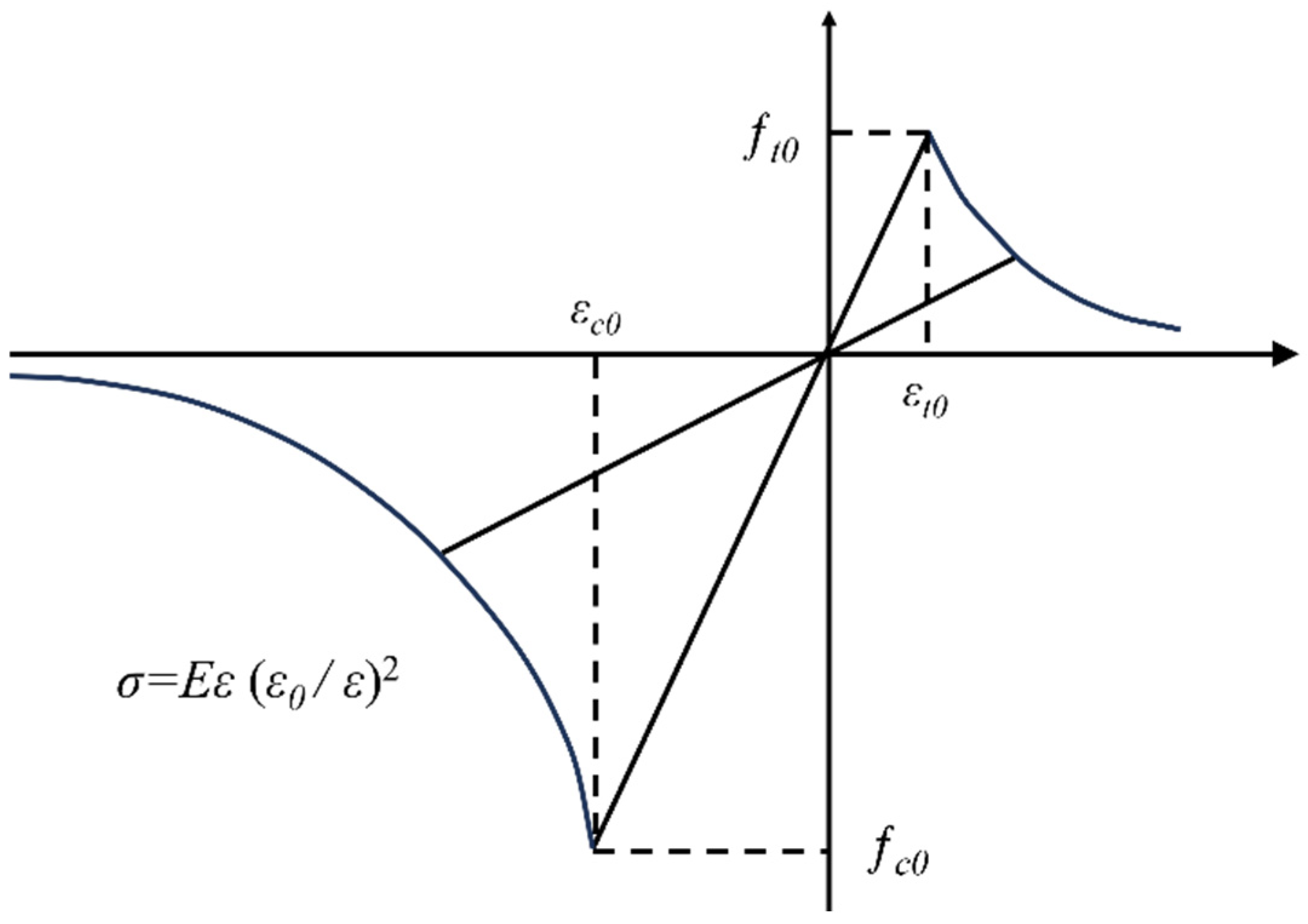
Under the combined action of drilling and gas pressure, the coal seam undergoes damage and even failure. According to damage mechanics theory, the evolution of the coal elastic modulus can be divided into two stages (Figure 1): in the elastic stage, the elastic modulus remains constant and no damage occurs; when the applied stress reaches the peak strength, damage and failure begin to develop in the coal [33].
The elastic modulus of coal during the damage process can be expressed as follows:
E = E 0 ( 1 D )
where E and E0 are the elastic modulus of the coal after and before damage, respectively; D is the damage variable.
The combined maximum tensile stress criterion and Mohr–Coulomb criterion are adopted to determine whether tensile or shear failure occurs in the coal under stress, and the corresponding failure criteria are given in Equation (8).
F 1 = σ 1 σ t = 0 F 2 = σ 3 + σ 1 1 + sin θ 1 sin θ σ c = 0
where σ1 and σ3 are the maximum and minimum principal stress, respectively; σt and σc are the uniaxial tensile and uniaxial compressive strength of the coal, respectively; θ is the angle of internal friction of the coal; and F1 and F3 are the threshold functions for tensile and shear damage, respectively.
The relationship between the damage and strain of the coal seam under the combined action of stress and gas pressure is given by Equation (9) [34].
D = 0                      F 1 < 0 , F 2 < 0 1 ε t 0 ε 1 2       F 1 = 0 , d F 1 > 0 1 ε c 0 ε 3 2       F 2 = 0 , d F 2 > 0
where ε1 is the maximum principal strain of coal; ε3 is the minimum principal strain of coal; εt0 is the ultimate tensile strain of coal when tensile damage occurs; and εc0 is the ultimate compressive strain of coal when shear damage occurs.

2.2. Site Conditions and Test Methods

2.2.1. Site Conditions

Xinyuan Coal Co., Ltd. is located in Shouyang County, Jinzhong City, Shanxi Province, in the northwestern part of the Qinshui Coalfield, in China. Measurements indicate that the Xinyuan mine has an absolute gas outflow rate of 196.727 m3/min and a relative gas outflow rate of 29.27 m3/t, classifying it as a high-gas outburst mine. Field tests were conducted at the No. 3 coal seam 31,001 working face and the No. 9 coal seam 9106 working face. The No. 3 coal seam 31,001 working face has a strike and dip length of 3238 and 239.4 m, respectively. This coal seam has an average thickness of 2.98 m, average dip angle of 4º, and a strength coefficient ranging from 0.50 to 0.58. The original gas content is 11.62 m3/t, with the gas pressure ranging from 0.53 to 0.64 MPa. The No. 9 coal seam 9106 working face has a strike and dip length of 1546.8 and 217 m, respectively. This coal seam has an average thickness of 2.45 m, average dip angle of 5º, and a strength coefficient ranging from 0.56 to 0.63. The original gas content is 7.48 m3/t, and the gas pressure ranges from 0.33 to 0.52 MPa.
To ensure safe coal mining operations, the Xinyuan company strictly implements the two “four-in-one” integrated outburst prevention measures. The local prevention strategy of the company primarily adopts Φ76 mm advanced gas discharge drilling technology. Prior to drilling, measuring and determining the EDR of boreholes at the working face of the coal seam is essential, as the accuracy of this parameter directly impacts both the efficient gas discharge of the coal seam gas and safe production of the mine. The drill cuttings index method provides a comprehensive assessment of gas discharge effectiveness, the S value of the drill cuttings volume reflects the stress distribution within the coal seam, whereas the K1 value of gas desorption from drill cuttings indicates the dynamic desorption characteristics of gas. The specific testing steps are as follows [35]:
(1) Construct an observation borehole at the selected measurement point within the coal seam working face. The borehole has a depth of 10 m and a diameter of 42 mm. Every 1 m, pause to collect and weigh all cuttings (S value) using a spring balance, then extract a 10 g sample to measure the gas desorption index K1 value using a WTC-type gas desorption index tester. Repeat until completion.
(2) After completing data collection for the observation borehole, ream the borehole to the predetermined discharge diameter (75 mm) and conduct a 2 h period of natural gas discharge.
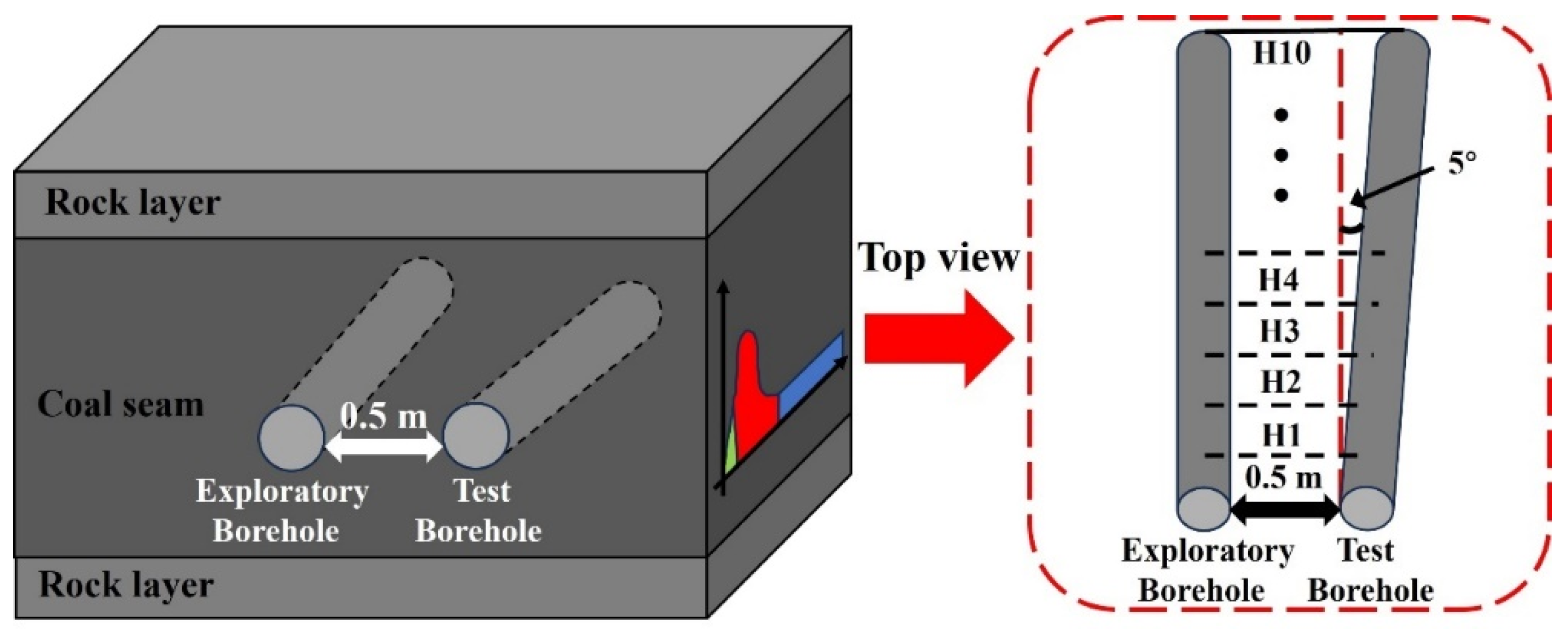
(3) After the natural gas discharge is completed, construct a test borehole 0.5 m from the observation borehole at an angle of 5° relative to it, as shown in Figure 2. Using the same procedure described in step (1), measure and record the S and K1 values for each meter drilled in the test borehole.

2.2.2. Principle for Determining the EDR of Boreholes

In the drill cuttings index method, the EDR is determined by comparing the S and K1 values before and after gas discharge. Prior to discharge, the S and K1 values reflect coal fragmentation and gas accumulation under original combined stress (geostress and gas pressure) [36]. After discharge, the gas pressure drops near the borehole, weakening the coal strength via the effective stress principle [37]. This causes coal damage, reducing the density, so the S value within the EDR becomes markedly lower than the initial S value. Damaged coal also has higher permeability, lowering the residual gas content [38]; thus, the K1 value within the EDR is also markedly smaller than the initial K1 value. By comparing field measurements from an observation borehole (pre-discharge) and a test borehole (post-discharge), if at depth H the test borehole’s S and K1 begin to exceed those of the observation borehole, that region lies outside the EDR. The EDR is then calculated using trigonometric relationships.
r = 2 l sin ( 2 . 5 ° ) + 0 . 5 / cos ( 2 . 5 ° )
where r denotes the EDR of the borehole, and l represents the borehole depth.

3. Results

3.1. Numerical Simulation Process

3.1.1. Establishing the Numerical Model

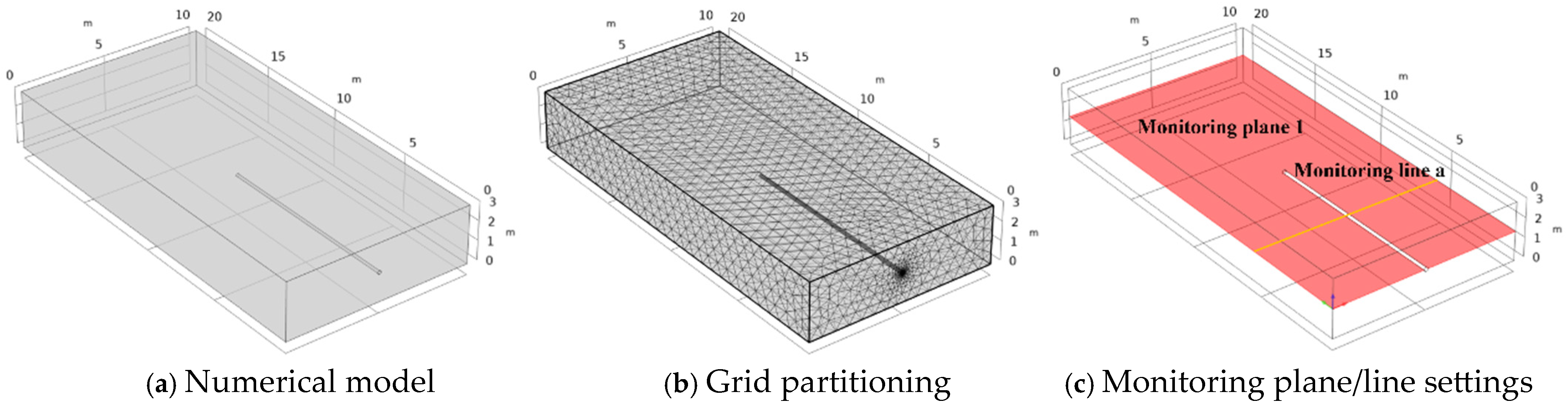
COMSOL Multiphysics 6.0, a finite element numerical simulation software, was employed to construct a multi-field coupled numerical model for gas discharge from coal seam boreholes, leveraging its built-in partial differential equation (PDE) solving capabilities. Figure 3a presents a three-dimensional coal seam model incorporating a borehole with a seam thickness, strike length, and width of 3, 20, and 10 m, respectively. To clearly characterize the quantitative evolution of gas within the coal seam, monitoring plane 1 is defined within the geometric model. This section passes through the center of the borehole and is aligned with the XY plane. Additionally, monitoring line a is established within monitoring plane 1 to track the quantitative evolution of coal seam gas pressure during borehole gas discharge, as shown in Figure 3c.

3.1.2. Boundary Conditions and Basic Parameters

The boundary conditions must be defined before the numerical simulation is conducted. The seepage boundary condition was established based on coalbed methane measurement data, with the initial gas pressure (P0) of the coal seam set to 0.37 MPa. Dirichlet boundary conditions were applied to the drilling region, where the gas pressure was specified as 0.10 MPa. The coal seam was located at approximately 500 m below ground level. Based on the relationship between the vertical stress and burial depth, the vertical stress at the upper boundary of the simulated model was set to 12 MPa. The bottom boundary of the model was fixed, while the lateral boundaries were constrained using roller supports. The basic parameters of the model are listed in Table 1. Among the numerical simulation parameters adopted in this study, the physical and mechanical parameters—including the coal density, elastic modulus, Poisson’s ratio, coal seam porosity, permeability, and initial temperature—were all obtained through laboratory tests. The gas diffusion coefficient and Langmuir adsorption constants were reasonably selected based on the existing literature [20].

3.1.3. Mesh Independence Verification

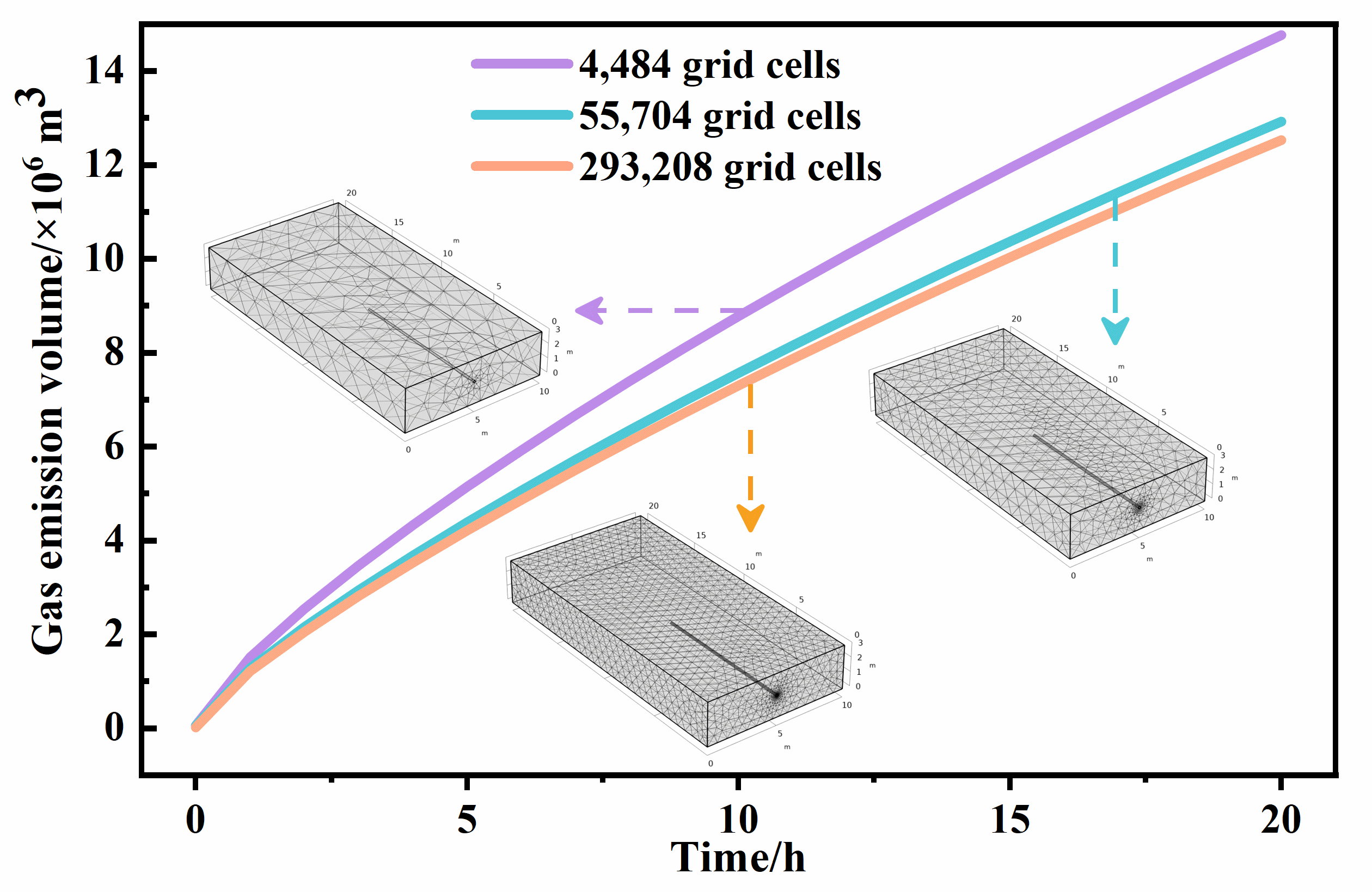
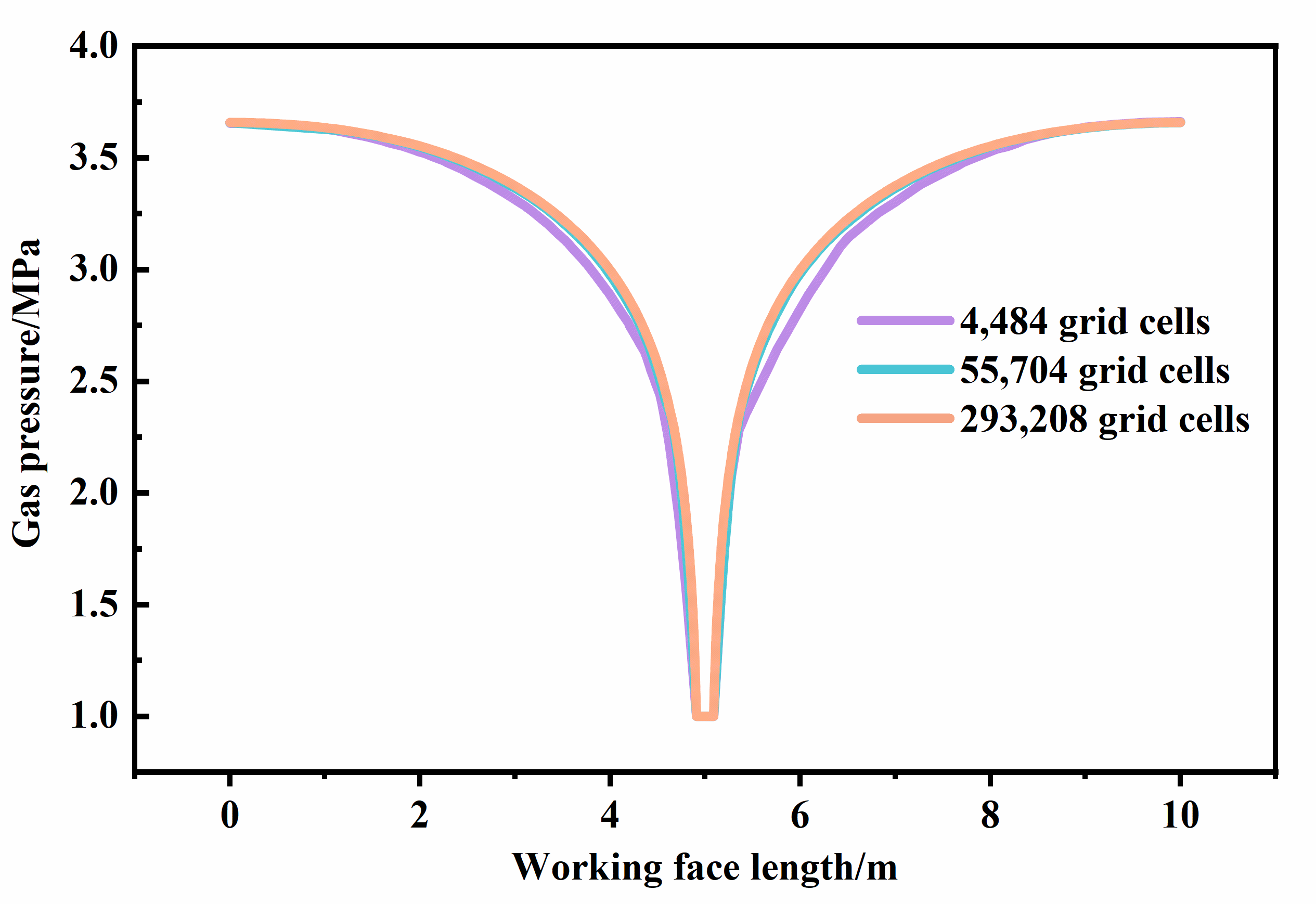
Prior to performing finite element simulations, the established model required mesh generation, as mesh quality directly affects the accuracy of simulation results [39]. In this study, the model was discretized using free tetrahedral elements, with localized mesh refinement applied near the borehole boundaries. To evaluate the influence of the mesh density on the simulation accuracy, a mesh independence analysis was conducted by generating models with varying numbers of meshes and comparing their corresponding simulation results, as shown in Figure 4. Monitoring gas discharges from the coal seam under different mesh densities revealed that when the number of elements exceeded 55,704, further mesh refinement had a negligible influence on the calculated gas discharge results, and the simulation outcomes became stable. Therefore, a mesh configuration consisting of 55,704 mesh elements was adopted for subsequent simulations in this study. Furthermore, the distribution patterns of gas pressure on monitoring line a under different grid quantities were comparatively analyzed. The results showed that when the number of grids increased from 55,704 to 253,208, the gas pressure distribution curves on monitoring line a were basically the same. This result indicates that the selected 55,704 grid scheme can effectively balance the calculation accuracy and resource consumption, meeting the numerical simulation requirements of this study.

3.2. Numerical Simulation Results

3.2.1. Influence of Time Factors on Gas Seepage Characteristics

(1) Gas seepage characteristics near boreholes at different time points
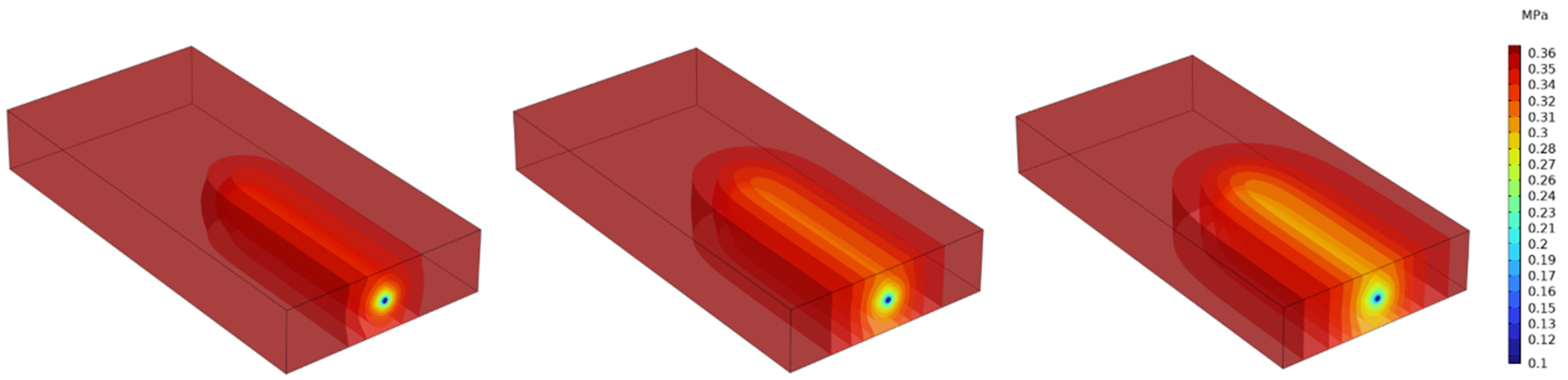
To investigate the influence of time factors on borehole gas discharge, simulations were conducted to capture the evolution of gas pressure within the coal seam at different stages of the discharge process, as shown in Figure 5. The simulation results indicate that, with the increasing discharge time, the gas pressure around the borehole continuously decreases, while the affected zone progressively expands. Figure 6 illustrates the spatial distribution of gas pressure during the discharge process. Vertically, the pressure relief region is constrained by the coal seam thickness; horizontally, the extent of the reduced gas pressure zone expands significantly over time.
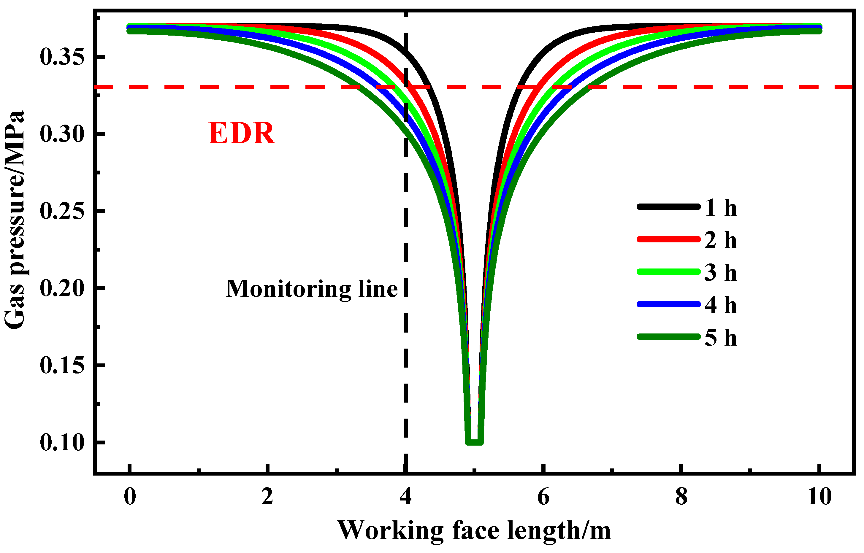
Figure 7 presents the changes in gas pressure along monitoring line a at different time points during the discharge process. Overall, the gas pressure on both sides of the borehole exhibits similar patterns of change. Regions closer to the borehole experience a more rapid decline in gas pressure, whereas areas farther away remain relatively stable, indicating that the influence of the borehole on the coal seam gas pressure remains spatially limited. Additionally, the rate of gas pressure reduction gradually decreases as the discharge time increases. Taking the monitoring point located 1 m to the left of the borehole as an example, the gas pressures at 1, 2, 3, 4, and 5 h were 0.352, 0.339, 0.330, 0.322, and 0.316 MPa, respectively, corresponding to hourly decay rates of 3.69%, 2.65%, 2.42%, and 1.86%. These results indicate that the gas discharge efficiency is relatively high during the initial stage of borehole operation and gradually transitions into a low-efficiency phase as discharge progresses.
(2) Damage characteristics at different time points
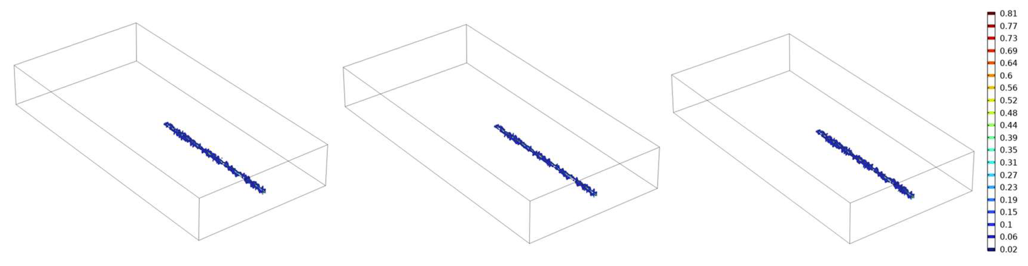
The spatiotemporal evolution of the damage zone within the coal seam during borehole gas discharge is illustrated in Figure 8. In the early stage of discharge, only a small amount of scattered and isolated damage appears around the borehole, with the damaged zones being relatively independent and discretely distributed. As discharge proceeds, the damaged zones gradually increase in number and evolve from a dispersed distribution toward a continuous and interconnected pattern, eventually forming a relatively complete damage band in the vicinity of the borehole.
(3) EDR of boreholes at different time points
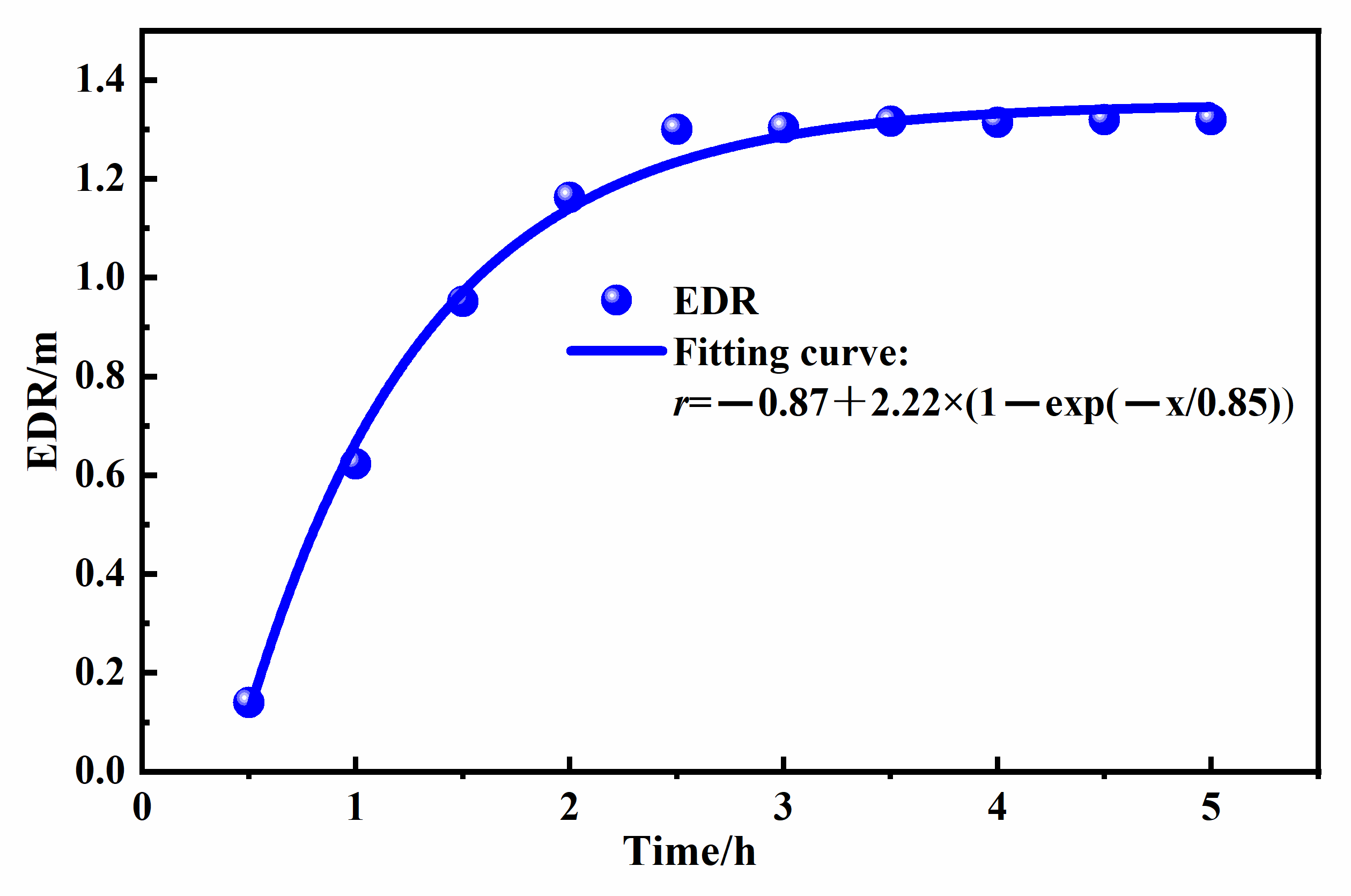
Based on previous studies, this study defines the EDR as the location where the coal seam gas pressure decreases by 10% from its initial value [40,41]. The initial coal seam pressure in this study was set at 0.37 MPa. Therefore, the position at which the gas pressure declined to 0.333 MPa was identified as the EDR of the borehole, as shown in Figure 7. Figure 9 illustrates the temporal evolution of the EDR, indicating a power-law relationship between the EDR and discharge time. During the initial phase of gas discharge, the EDR increases rapidly; however, the rate of growth gradually stabilizes during later stages. The EDR values at 1, 2, 3, 4, and 5 h were 0.64, 0.93, 1.16, 1.31, and 1.43 m, respectively, corresponding to hourly EDR growth rates of 45.3%, 24.7%, 12.9%, and 9.2%. These results further demonstrate that the effective influence range of boreholes on coal gas discharge is limited. Consequently, selecting an appropriate discharge duration is essential: excessively long discharge periods may lead to significantly reduced efficiency in later stages, whereas overly short discharge durations may prevent full utilization of the gas extraction capacity of the borehole.

3.2.2. Influence of Borehole Diameter on Gas Seepage Characteristics

(1) Gas seepage characteristics near boreholes with different borehole diameters
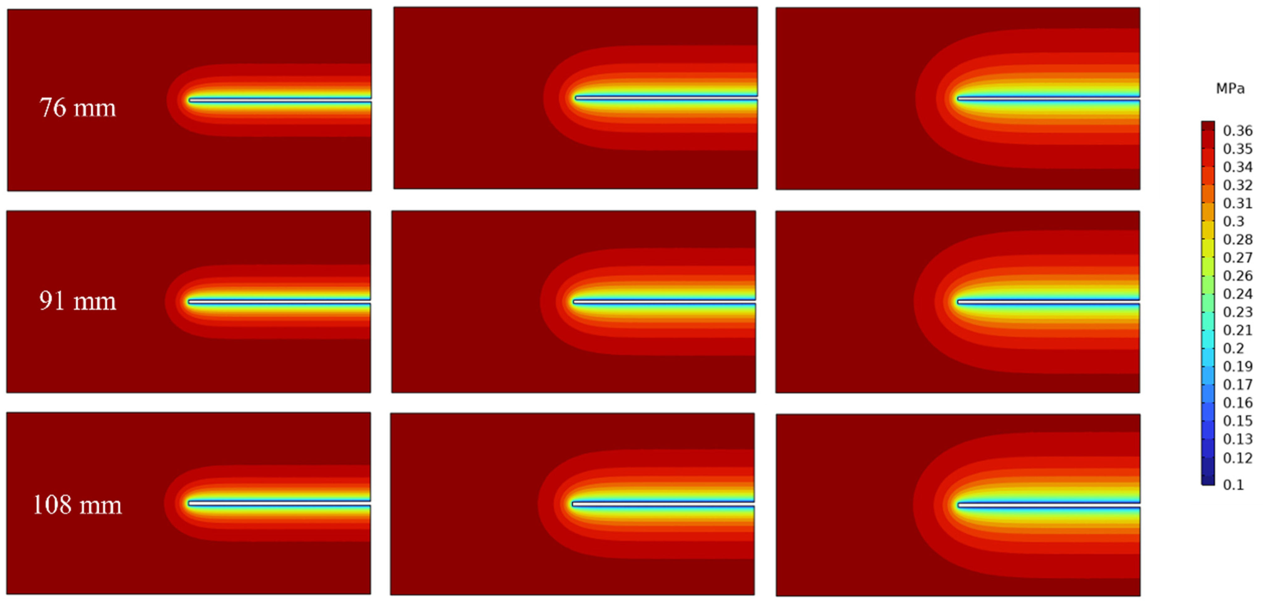
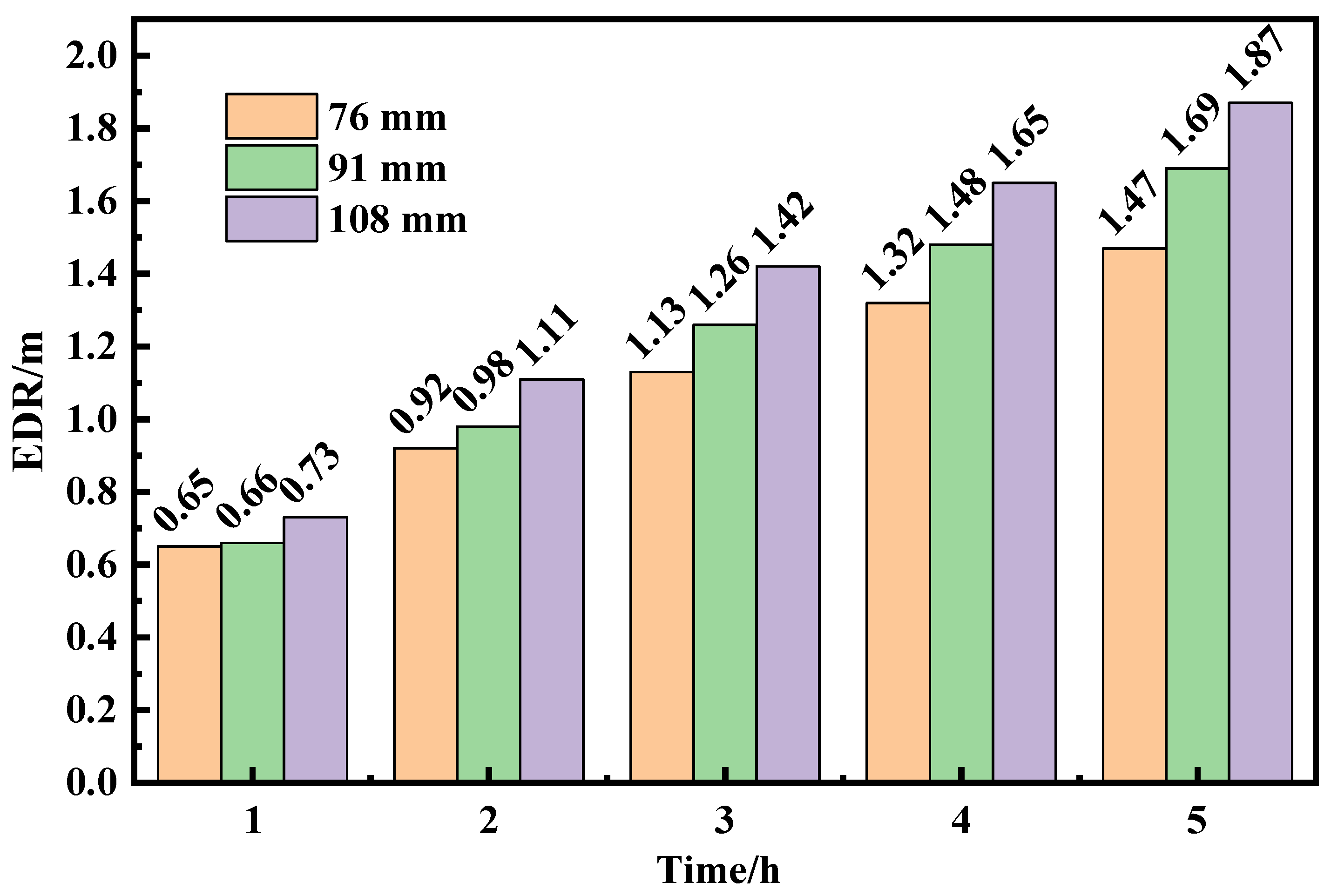
In coal mining faces, borehole diameters used for gas discharge typically range from 75 to 120 mm [42]. To evaluate the influence of borehole diameters on gas seepage behavior, simulations were conducted for boreholes with diameters of 76, 91, and 108 mm. Figure 10 illustrates the gas seepage characteristics observed at monitoring plane 1 for boreholes of varying diameters. The results indicate that, under the same gas discharge duration, increasing the borehole diameter expands the zone of gas pressure reduction within the coal seam and enhances the gas discharge efficiency. Furthermore, as the discharge time increases, the EDR associated with larger-diameter boreholes gradually expands. Larger borehole diameters provide less resistance to gas flow, thereby facilitating rapid gas migration, accelerating pressure reduction in the coal seam, and enhancing the overall discharge performance.
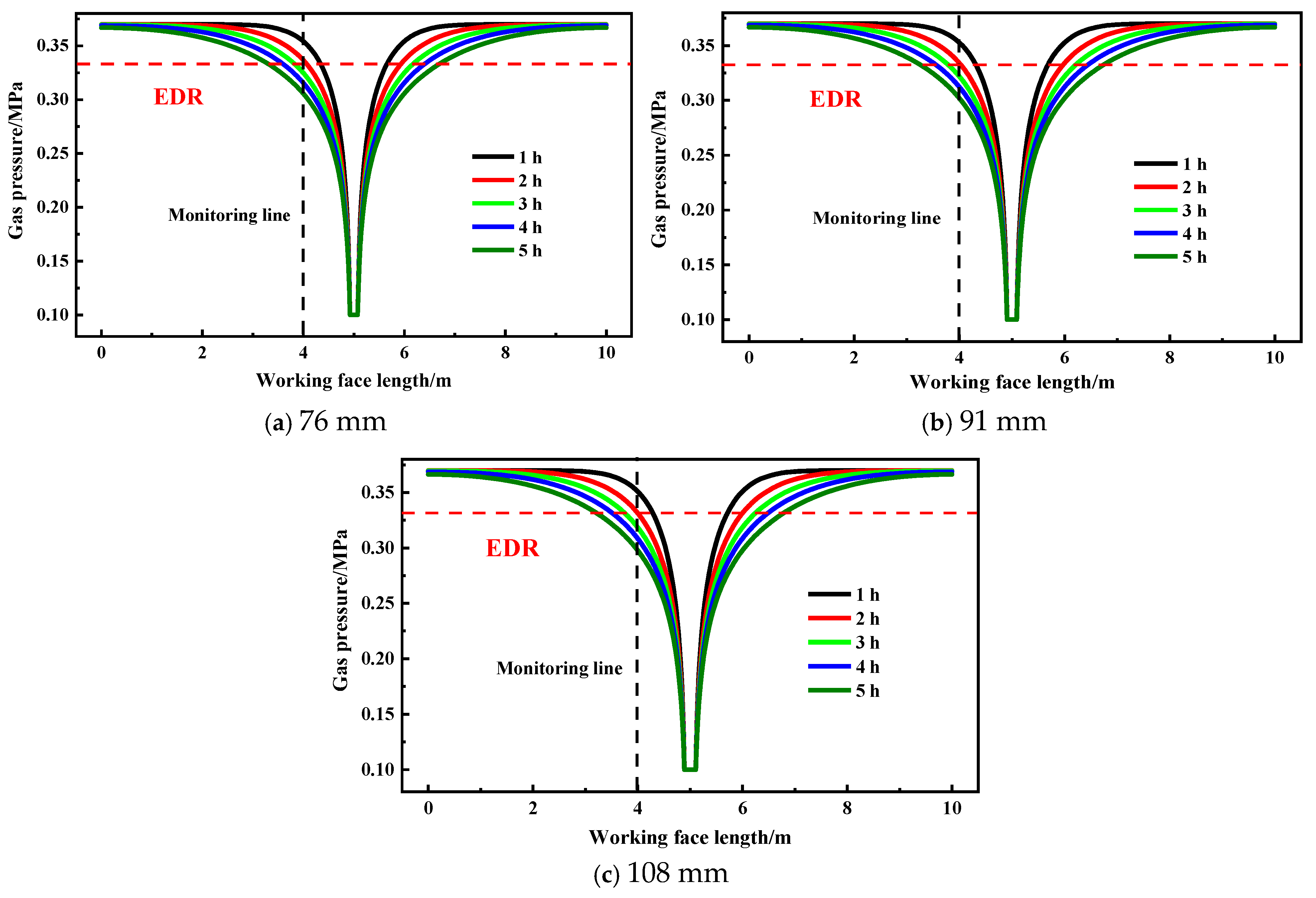
Figure 11 illustrates the gas pressure distribution along monitoring line a for different borehole diameters. Overall, similar pressure along monitoring line 1 exhibits similar variation patterns across different diameters: gas pressure decreases more rapidly near the borehole, whereas it remains relatively stable in regions farther away within the coal seam. Additionally, increasing the borehole diameter leads to a higher hourly gas pressure decay rate. Taking the monitoring point located 1 m from the borehole as an example, when the borehole diameter increased from 76 to 108 mm, the hourly gas pressure reductions increased from 0.016, 0.012, 0.012, 0.010, and 0.010 MPa to 0.021, 0.020, 0.013, 0.010, and 0.010 MPa, respectively. These results indicate that enlarging the borehole diameter significantly enhances the gas discharge efficiency during the early-stage gas discharge, while its influence on the later-stage gas discharge efficiency is comparatively limited.
(2) Damage characteristics at different borehole diameters
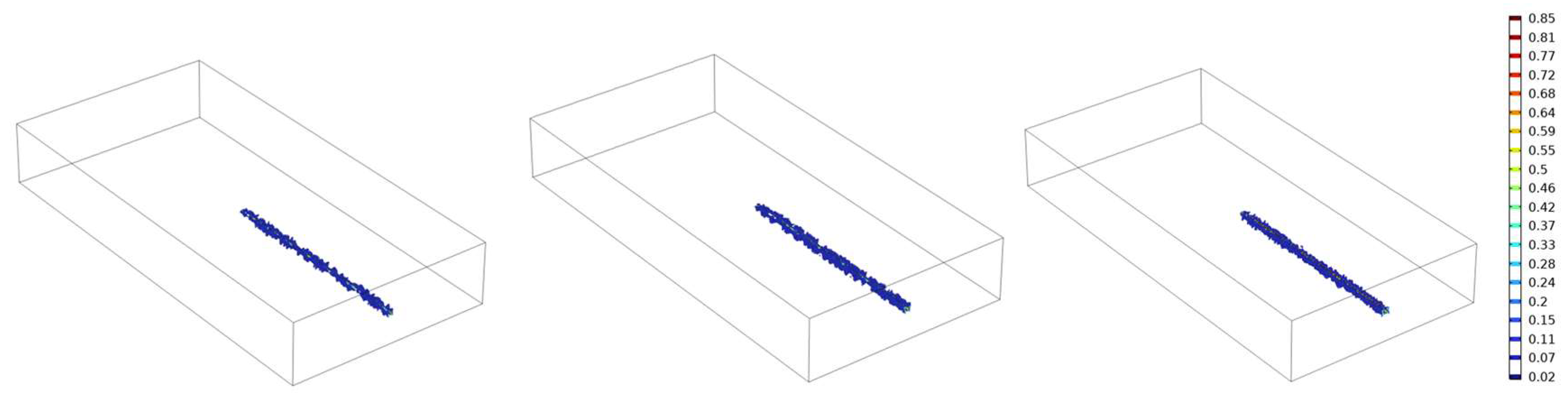
The numerical simulation results of coal seam damage under different borehole diameters are presented in Figure 12. Under small-diameter conditions, the damage zone around the borehole is relatively narrow and discontinuous, which is favorable for safe operation. As the borehole diameter increases, both the extent and degree of the damage zone gradually increase. Therefore, an optimal balance between the gas discharge efficiency and borehole wall stability should be sought in borehole design. Once the borehole diameter exceeds a certain threshold, the damage and failure of coal adjacent to the borehole will be exacerbated, leading to a sharp deterioration in borehole wall stability.
(3) EDR of boreholes at different borehole diameters
Figure 13 illustrates the influence of the borehole diameters on the EDR. Overall, the EDR exhibits a power-law growth trend with the increasing discharge time. Furthermore, enlarging the borehole diameter results in a progressive increase in the EDR. When the borehole diameter increased from 76 to 108 mm, the EDR increased by 12.3%, 20.7%, 25.1%, 25.7%, and 26.2% after 1, 2, 3, 4, and 5 h of gas discharge, respectively, with corresponding hourly growth rates of 7.5%, 3.6%, 0.5%, and 0.4%, respectively. These results indicate that enlarging the borehole diameter significantly accelerates EDR expansion during the first 3 h of gas discharge, whereas the growth rate gradually decreases and stabilizes thereafter. During coal seam drilling, larger borehole diameters tend to induce more fractures around the borehole, which enhances the gas migration efficiency and improves the overall discharge performance, thereby increasing the EDR. However, excessively large diameters may increase construction difficulty and elevate the risk of borehole collapse, particularly in soft coal seams. Therefore, in practical drilling operations, the borehole diameter must be selected carefully by considering the equipment capacity and coal seam mechanical properties.

3.2.3. Influence of Coal Seam Permeability on Gas Seepage Characteristics

(1) Gas seepage characteristics near boreholes at different coal seam permeabilities
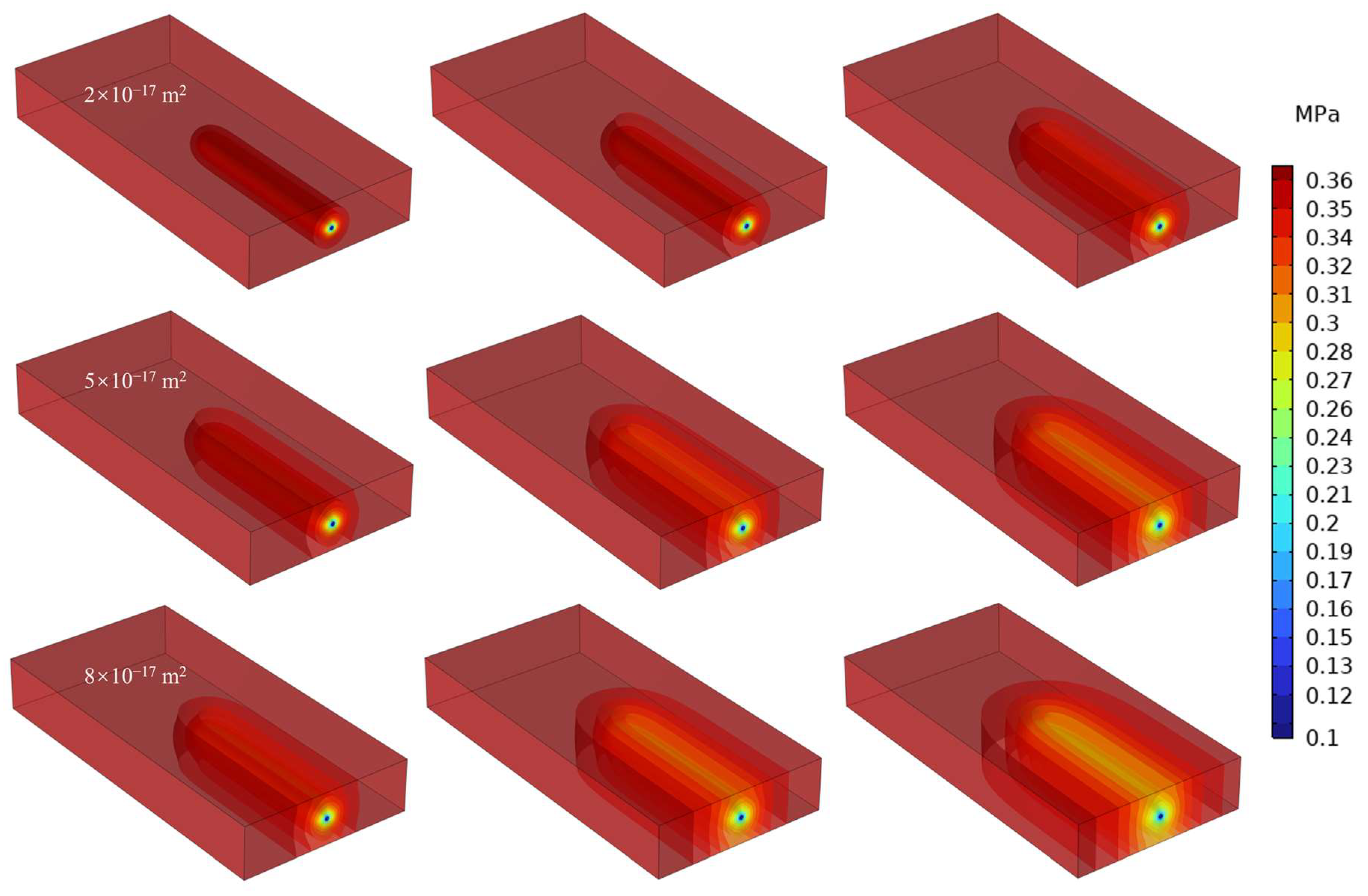
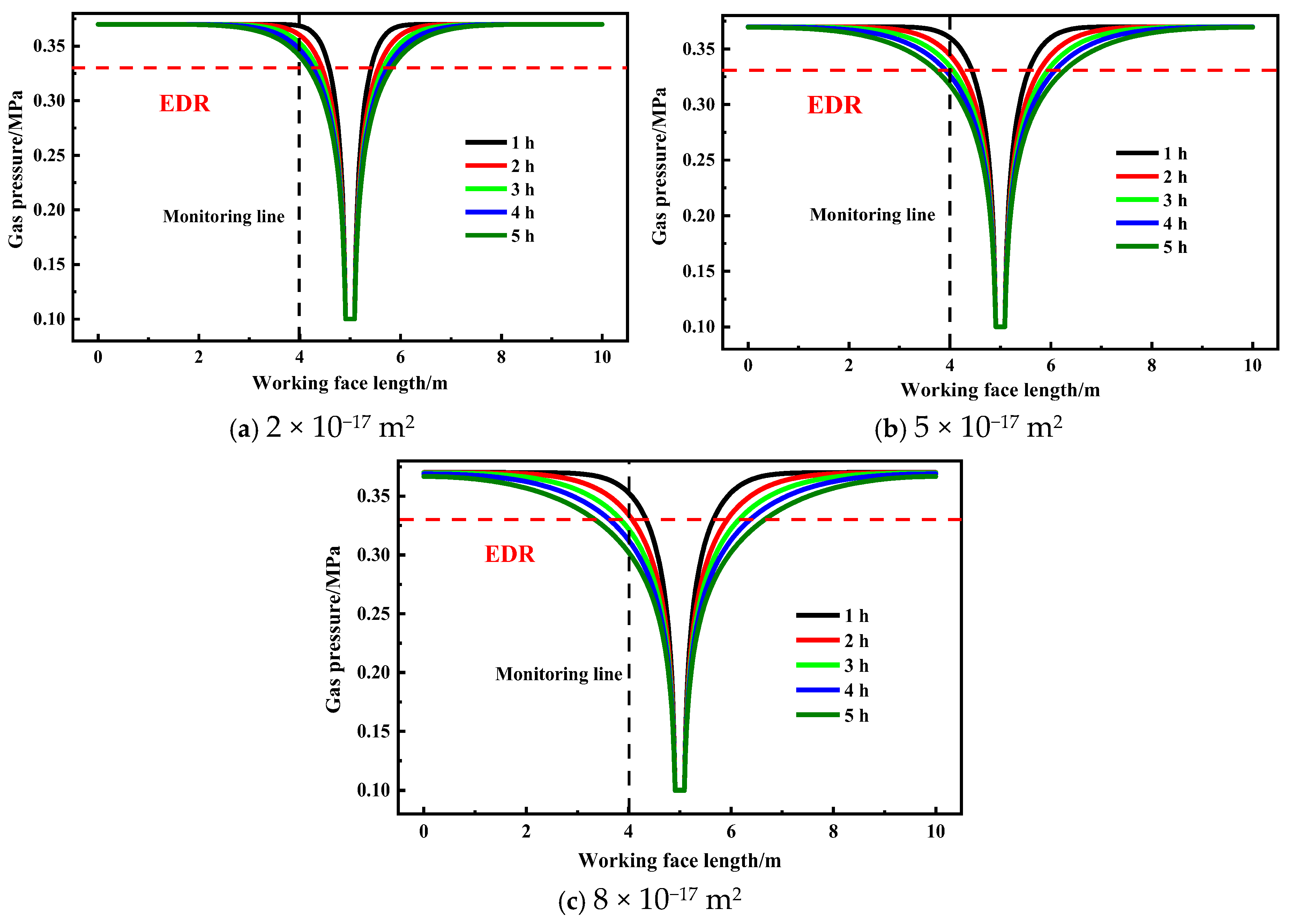
To investigate the influence of coal seam permeability on borehole gas seepage behavior, the initial permeability of the coal seam was set to 2 × 10⁻¹⁷, 5 × 10⁻¹⁷, and 8 × 10⁻¹⁷ m2. Figure 14 illustrates the spatial evolution of gas pressure within coal seams under different permeability conditions. Overall, the zone influenced by gas discharge expands markedly with the increasing discharge time. Additionally, at the same time point, coal seams with higher permeability exhibit a larger pressure relief zone. Taking a gas discharge duration of 5 h as an example, the affected area remains relatively limited in coal seams with the lowest permeability, whereas in higher-permeability coal seams, gas pressure reduction extends significantly in the horizontal direction. These results indicate that increased permeability reduces gas flow resistance within the coal seam, thereby facilitating more rapid gas migration and diffusion toward the external environment.
Figure 15 presents the quantitative relationship between coal seam permeability and gas discharge performance. The results indicate that, with the increasing discharge time, the gas pressure decreases more rapidly in coal seams with higher permeability. Taking the monitoring point located 1 m from the borehole as an example, when the coal seam permeability increases from 2 × 10⁻¹⁷ to 5 × 10⁻¹⁷ and 8 × 10⁻¹⁷ m2, the gas pressures after 5 h were 0.341, 0.317, and 0.302 MPa, respectively, corresponding to reductions of 7.8%, 14.3%, and 18.4%. These findings demonstrate that, during borehole gas discharge, high-permeability coal seams exhibit more efficient gas extraction, resulting in a greater pressure reduction within the same time period.
(2) Damage characteristics at different coal seam permeabilities
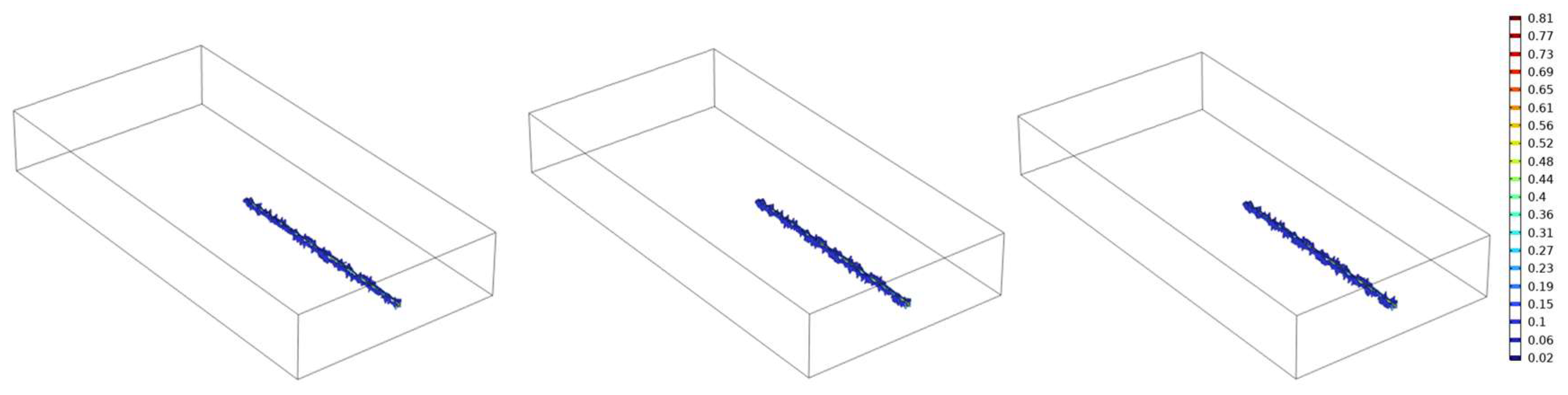
The distribution characteristics of internal damage in the coal seam during borehole gas discharge under different permeability conditions are illustrated in Figure 16. After 5 h of gas discharge, damage occurs in the vicinity of the borehole in all coal seams with varying permeabilities, and the spatial distribution patterns are generally similar. However, the damage zone near the borehole is more extensive in coal seams with higher permeability. Therefore, in field gas control practices, strengthened borehole support measures should be adopted for high-permeability coal seams to mitigate the risk of borehole wall instability that may arise from aggravated damage around the borehole wall.
(3) EDR of boreholes at different coal seam permeabilities
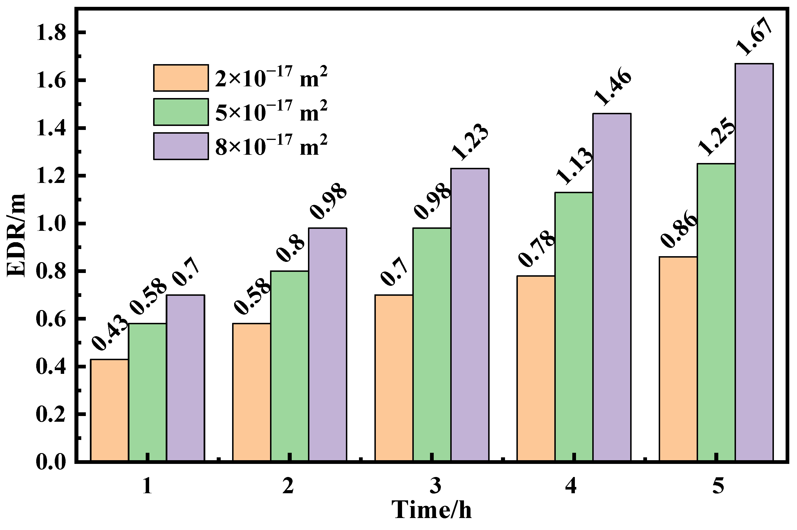
Figure 17 illustrates the influence of coal seam permeability on the EDR of boreholes. At the same discharge duration, increasing the coal seam permeability significantly enlarges the EDR, and this effect becomes more pronounced as the discharge duration extends. When the coal seam permeability increased from 2 × 10⁻¹⁷ to 8 × 10⁻¹⁷ m2, the EDR increased by 62.8%, 68.9%, 75.7%, 87.2%, and 94.2% after 1, 2, 3, 4, and 5 h of gas discharge, respectively. Furthermore, during the gas discharge process, the influence of the coal seam permeability on the EDR was more significant than that of the discharge duration. After 5 h of discharge, the EDR in high-permeability coal seams (8 × 10⁻¹⁷ m2) was approximately twice that observed in low-permeability coal seams (2 × 10⁻¹⁷ m2). These findings demonstrate that coal seam permeability plays a critical role in determining the effectiveness of borehole gas discharge. Under higher-permeability conditions, satisfactory gas discharge performance can be achieved even with shorter discharge durations. Therefore, in low-permeability coal seams, appropriate permeability enhancement measures should be implemented according to site-specific conditions to improve gas discharge efficiency.

3.2.4. Influence of Borehole Layout on Gas Discharge Characteristics

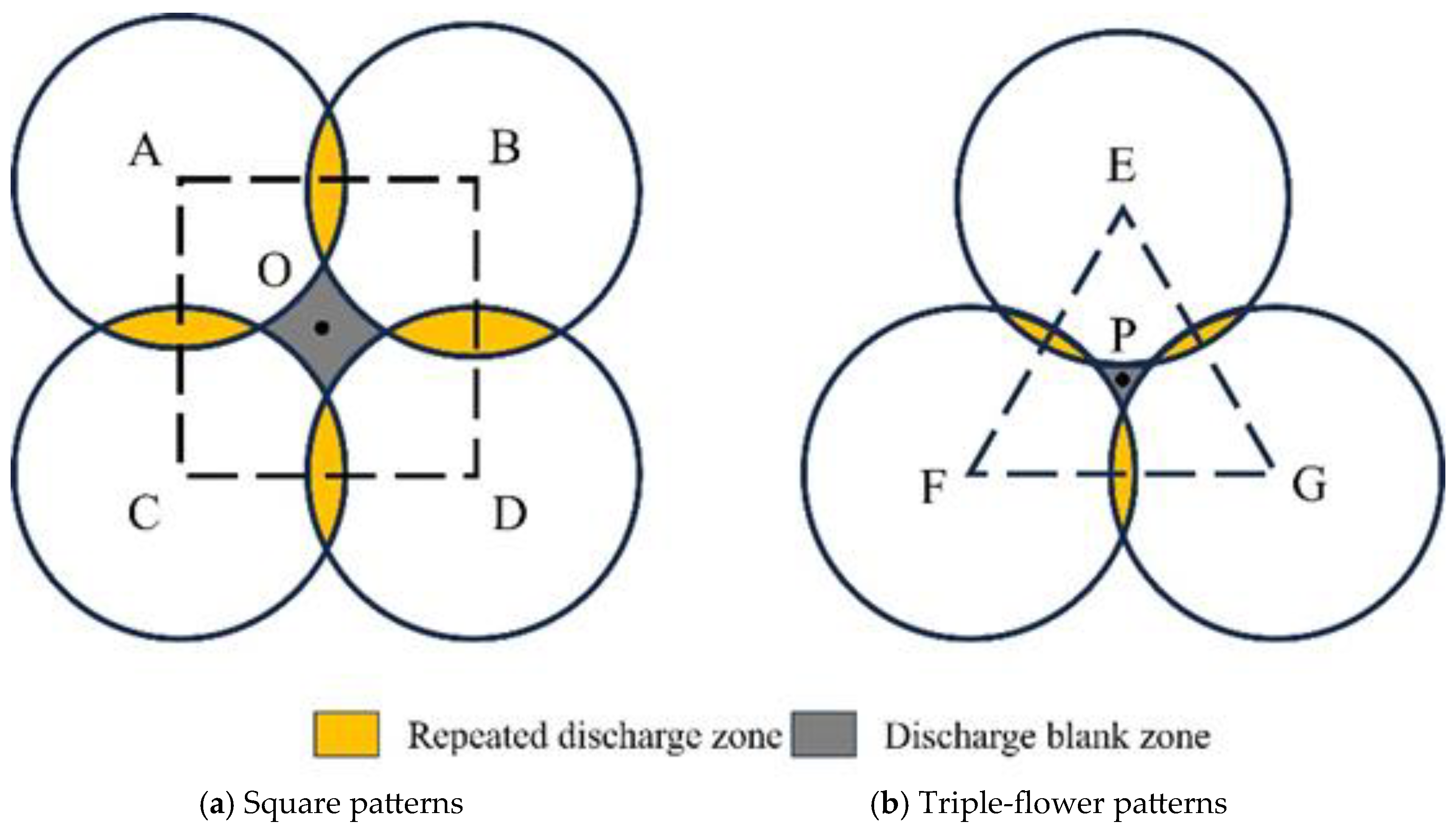
To enhance borehole gas discharge efficiency while minimizing labor and material consumption, rational design of borehole layouts is essential [43]. Accordingly, this study compares gas permeation patterns under commonly used borehole configurations. The square and triple-flower patterns are among the most frequently applied layouts in coal mines [44], as shown in Figure 18. Points A–F represent different borehole positions, with an inter-borehole spacing of R = 2 m. Point O denotes the center of the square borehole layout, where points A, B, C, and D are located at coordinates (4, 2.5), (6, 2.5), (4, 0.5), and (6, 0.5), respectively. Point P represents the center point of the triple-flower layout, with boreholes E, F, and G positioned at coordinates (5, 1.5 + 2√3/3), (4, 1.5 − √3/3), and (6, 1.5 − √3/3), respectively.
(1) Gas seepage characteristics near boreholes at different borehole layouts
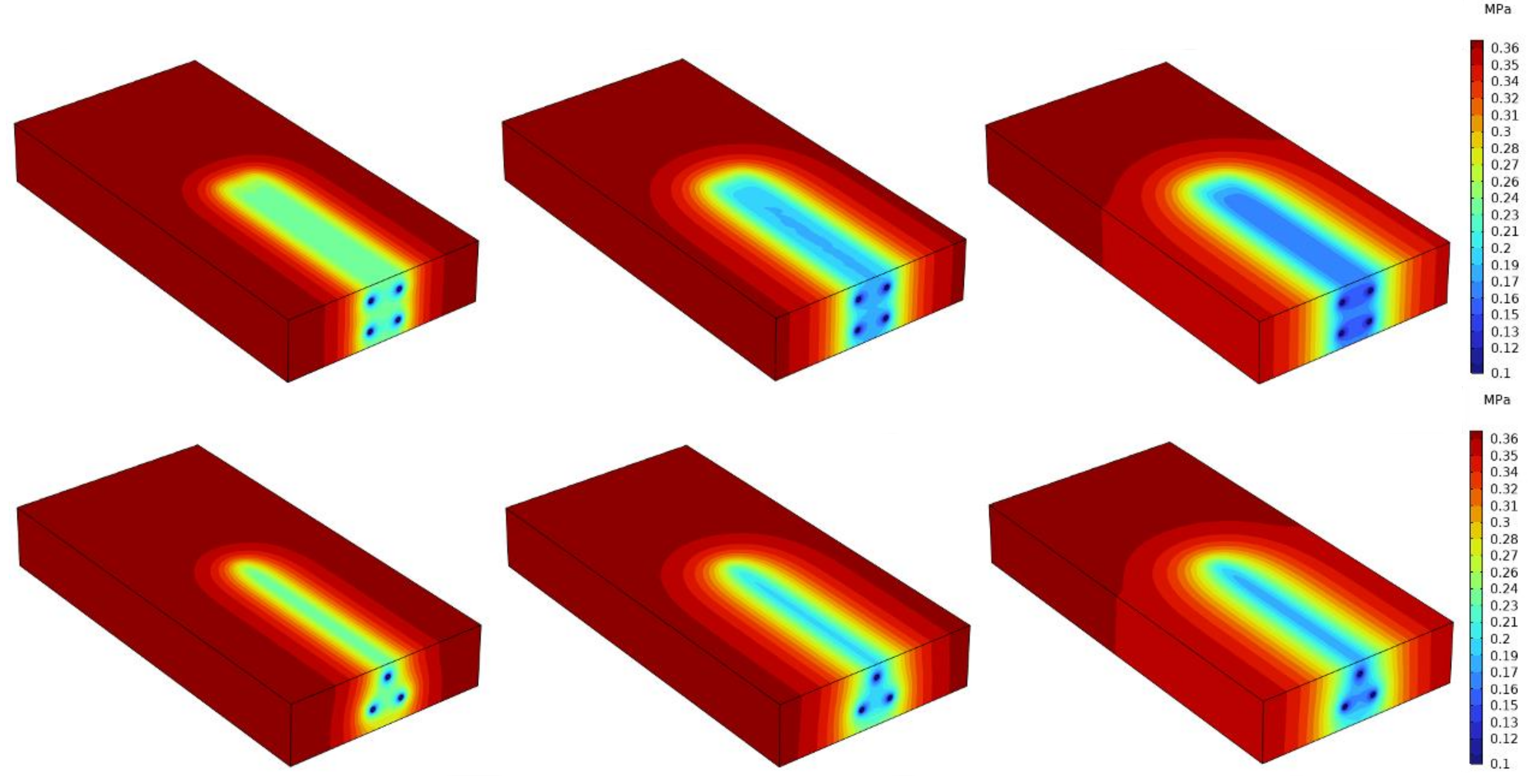
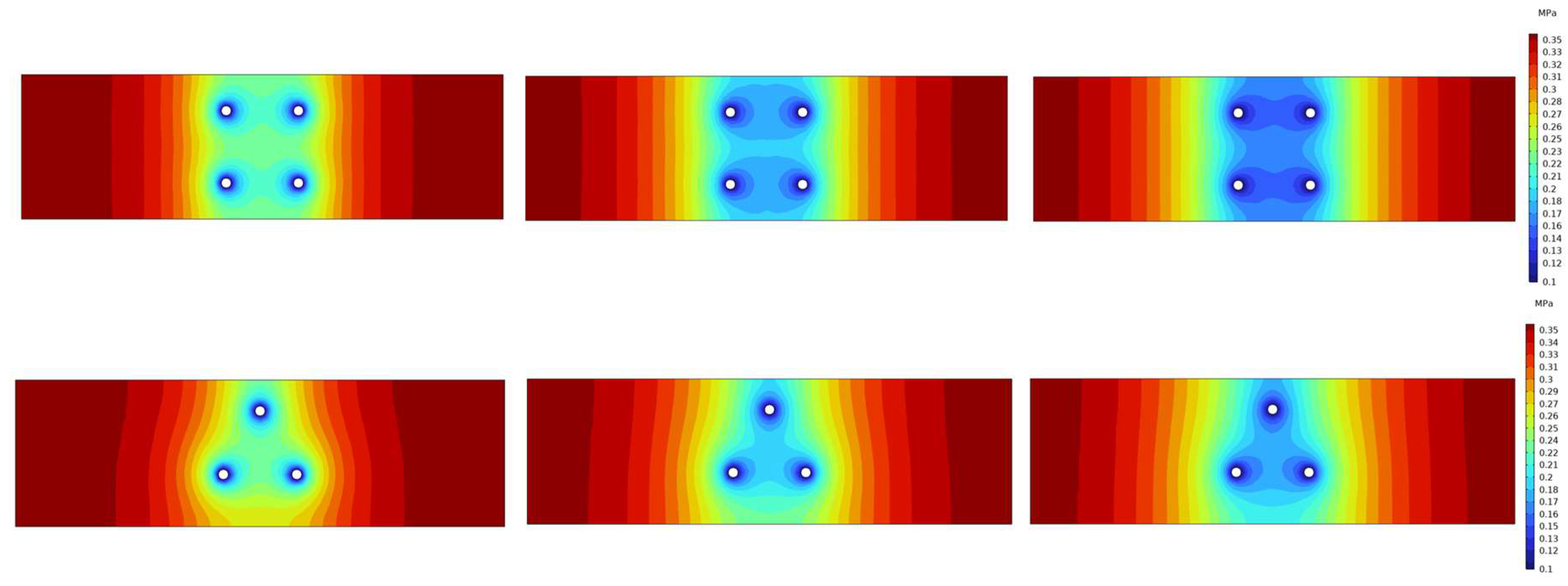
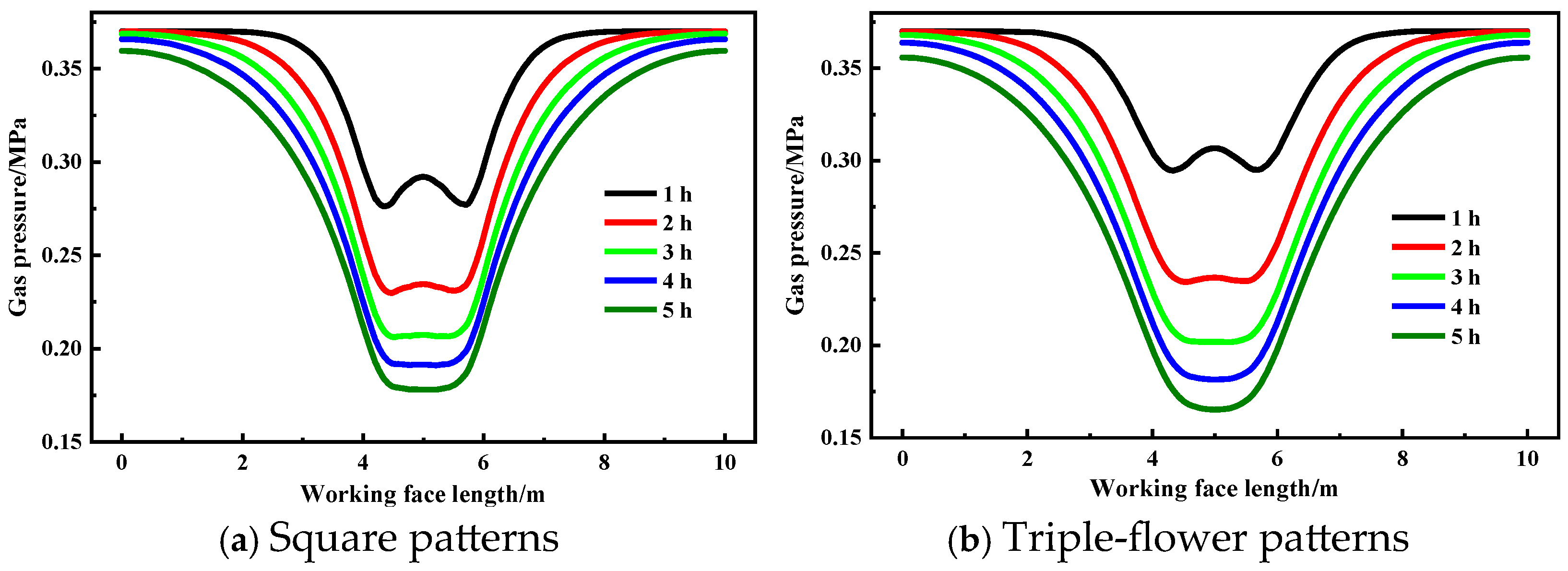
Figure 19 illustrates the gas permeation patterns associated with different borehole layouts. Overall, the zone influenced by gas discharge expands continuously with the increasing discharge time. However, the spatial evolution of gas pressure varies depending on the selected layout. Figure 20 illustrates the gas pressure distribution in the coal seam ahead of the boreholes. Owing to differences in geometric arrangement, the gas pressure relief zone produced by the square layout generally exhibits a near-rectangular distribution, whereas the triple-flower layout forms a near-triangular pressure distribution in the vicinity of the boreholes.
Figure 21 presents the variation in gas pressure along monitoring line 1 under different drilling layouts. The results indicate that changes in borehole configuration significantly affect the spatial distribution of gas pressure within the coal seam. Compared with a single-borehole arrangement, multi-borehole configurations tend to generate a localized high-gas-pressure zone near the midpoint of the coal seam. This phenomenon occurs because, during the initial stage of gas discharge, gas in proximity to the boreholes is preferentially extracted owing to pressure gradients. By contrast, gas located in the central area, being farther from individual boreholes, may experience delayed discharge, leading to a lag in pressure reduction and the temporary formation of a relatively high-pressure zone.
(2) Damage characteristics at different pore distribution patterns
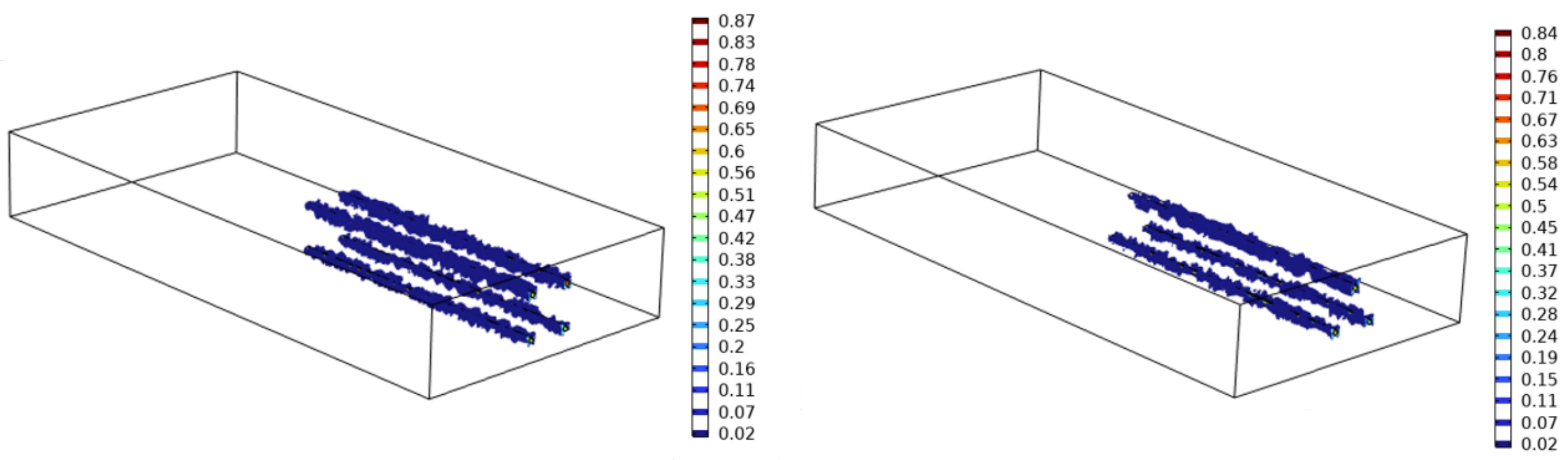
The distribution characteristics of coal damage during gas discharge under different borehole layout patterns are illustrated in Figure 22. Although the borehole arrangements differ, the damaged zones under both schemes are mainly concentrated around the boreholes. However, compared with the three-flower pattern, the square pattern induces stronger interference effects among boreholes, resulting in more pronounced cumulative damage. This finding suggests that in practical gas control engineering, blindly increasing the borehole density in pursuit of a higher discharge efficiency may exacerbate coal damage and elevate the risk of borehole wall instability.
(3) EDR of boreholes at different borehole layouts
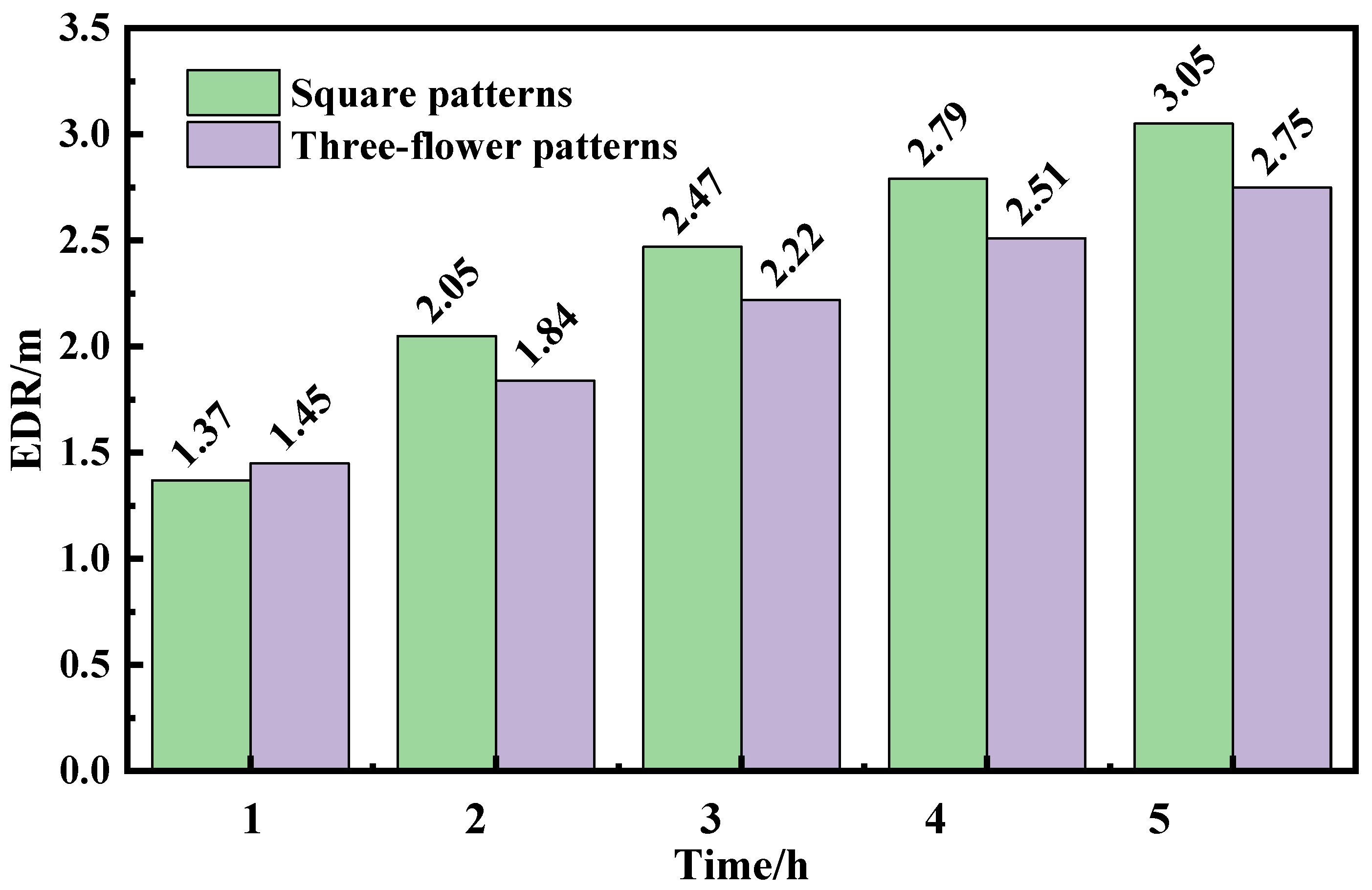
Figure 23 illustrates the impact of different borehole layouts on the EDR during the gas discharge process. Overall, the EDR exhibits a power-law relationship with time. Specifically, during the initial phase of gas discharge, the EDR increases rapidly on an hourly basis. In the later stages, the hourly growth rate decreases and gradually stabilizes. Taking the square pattern as an example, the EDR of the boreholes increased from 1.37 to 2.05, 2.47, 2.79, and 3.05 m at 1, 2, 3, 4, and 5 h, respectively, corresponding to increases of 49.6%, 20.5%, 12.9%, and 9.3%. Furthermore, prior to the first hour of gas discharge, the EDR was larger for the triple-flower pattern. However, after the first hour of gas discharge, the EDR becomes greater when using the square pattern, enabling more residual gas to be discharged from the coal seam.

3.2.5. Discussion

The dynamic growth of the borehole effective discharge radius (EDR) over time is essentially the result of the coal seam gas pressure field continuously expanding in space and evolving over time under negative pressure drive, and this process becomes even more complex due to the superposition and interference effects of pressure fields under multi-borehole conditions.
In the early stage of gas emission from a single borehole, the gas pressure gradient around the borehole is at its maximum, and gas flows toward the borehole at a high rate driven by the pressure difference, causing the EDR to expand rapidly outward. As time progresses, a large amount of gas is discharged from the coal seam, the pressure gradient gradually weakens, and the EDR growth rate slows down and eventually stabilizes. In the case of multi-borehole gas emission, the negative pressure zones independently formed by each borehole overlap spatially, producing a superposition effect. In the early stage of gas emission, the influence ranges of the negative pressure from each borehole have not yet intersected, and they act independently; as the emission time increases, the depressurized zones in the coal seam gradually expand outward and become interconnected, and the superposition effect is significantly enhanced. Within the superposition zone, the simultaneous emission from multiple boreholes causes a much greater gas pressure drop than that from single-borehole extraction, and the EDR growth rate exceeds that of a single borehole. However, this acceleration effect gradually diminishes as gas emission enters the later stage and the overall pressure gradient in the coal seam declines, eventually also tending to stabilize. Therefore, the superposition effect is most pronounced during the middle stage of extraction, which is the critical period for optimizing borehole layout design.

3.3. Parameter Sensitivity Analysis

To investigate the influence of key simulation parameters on the EDR, three factors, namely the elastic modulus E, Poisson’s ratio ν, and gas diffusion coefficient D, were selected for parameter sensitivity analysis. The specific simulation schemes are presented in Table 2. Using the parameters of Group 1 as the baseline scheme, simulation calculations show that the EDR distance from the borehole center at 3 h after gas emission is 1.38 m. To obtain the sensitivity ranking of each factor, the EDR distances from the borehole center under the nine schemes at this time point were extracted as response values. The results are summarized in Table 2.
From the variance analysis results in Table 3, it can be seen that the order of the sum of squares of deviations for each factor is gas diffusion coefficient > elastic modulus > Poisson’s ratio, indicating that there are significant differences in the sensitivity of the three factors to the EDR. At a significance level of α = 0.05, the p values for both the gas diffusion coefficient and the elastic modulus are less than 0.05, showing that they have significant effects on the EDR; whereas the p value for Poisson’s ratio is greater than 0.05, indicating that its effect on the EDR is not significant. Combining the F values and the ranking of the sum of squares of deviations, the sensitivity of the three factors to the EDR, from strong to weak, is: gas diffusion coefficient, elastic modulus, Poisson’s ratio. Thus, the gas diffusion coefficient is the dominant factor controlling the effective discharge radius, followed by the elastic modulus, while the influence of the Poisson’s ratio is negligible within the parameter range considered in this study. Therefore, in practical engineering, if the aim is to increase the effective discharge radius of boreholes within a limited time, the most effective technical approach is to prioritize permeability enhancement measures that improve or optimize the gas diffusion coefficient (e.g., hydraulic slotting, loose blasting, etc.).

3.4. Field Validation

3.4.1. Drill Cuttings Volume S Value

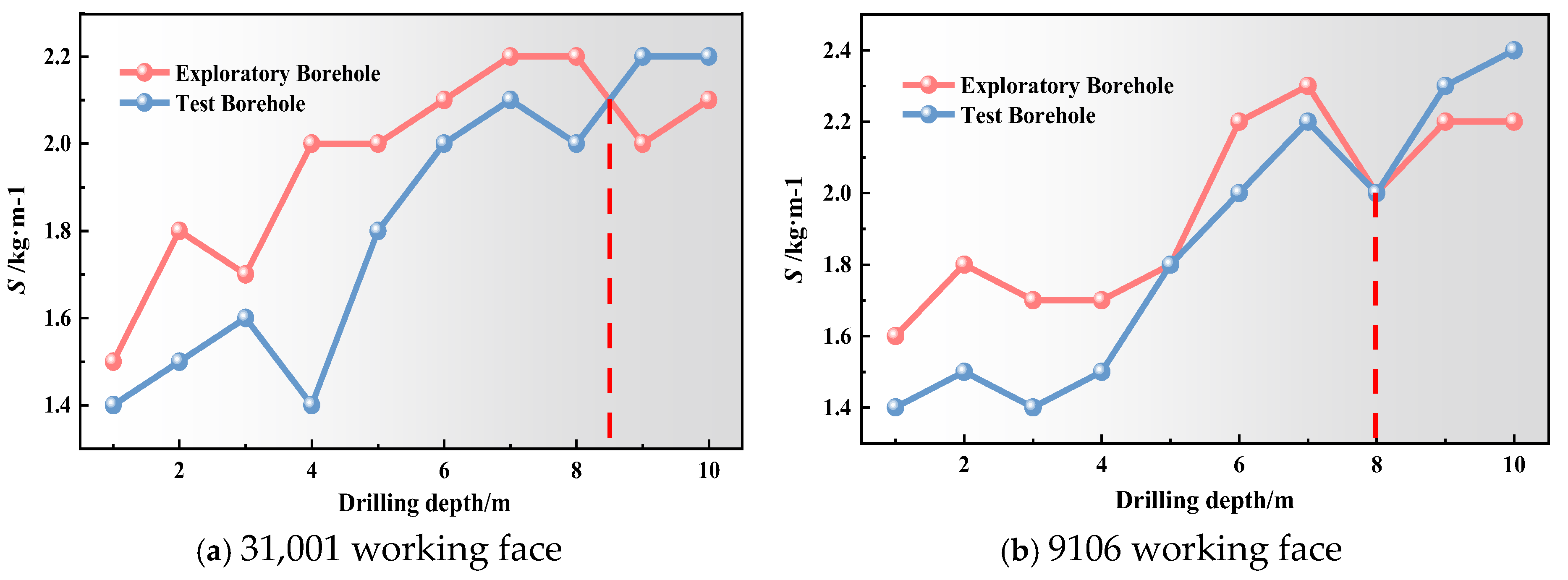
Field measurements of the drill cuttings volume S value obtained during drilling operations at the No. 3 coal seam 31,001 and No. 9 coal seam 9106 working faces at Xinyuan Coal Mine are presented in Figure 24. The results indicate that, with the increasing drilling depth, the S value initially decreases and then increases. Comparison of the variations in the S values of drill cuttings generated during the observation and test borehole drilling processes indicated that after 2 h of gas discharge, the S value of drill cuttings from the 76 mm diameter test borehole began to exceed that of the observation borehole at a depth of 8.5 m. According to Equation (10), the EDR of the boreholes at the No. 3 coal seam 31,001 working face at Xinyuan Coal Mine is 1.24 mm. Similarly, the EDR of boreholes at the No. 9 coal seam 9106 working face is 1.20 mm.
The S value of drill cuttings generated during drilling operations is closely related to the coal density [45]. Under the influence of mining disturbance, the coal seam ahead of the working face typically develops three zones sequentially along the advance direction: a stress relaxation zone, a stress concentration zone, and an original stress zone [46]. These three zones evolve dynamically as the mining face advances, as illustrated in Figure 2. As a key preventive measure against coal–rock dynamic disasters, drilling operations redistribute stresses within the coal seam. Within the stress relaxation zone, the coal has already undergone damage expansion and exhibits relatively low density [47]. Secondary disturbance during drilling further promotes coal failure and fragmentation, resulting in a further decrease in the S value per unit length of the drilled borehole. As drilling progresses deeper and approaches the stress concentration zone, the coal undergoes compaction under high in situ stress, resulting in a significant increase in density [48]. Consequently, the S value begins to increase. By contrast, coal within the original stress zone remains in an initial stress equilibrium state, where its density and mechanical properties remain largely unchanged [49]. Because drilling operations typically begin near the stress relaxation zone adjacent to the working face and gradually advance toward the stress concentration zone as the borehole deepens, the S value of drill cuttings exhibits a characteristic trend of initially decreasing and then increasing.

3.4.2. Drill Cuttings Gas Desorption K1 Value

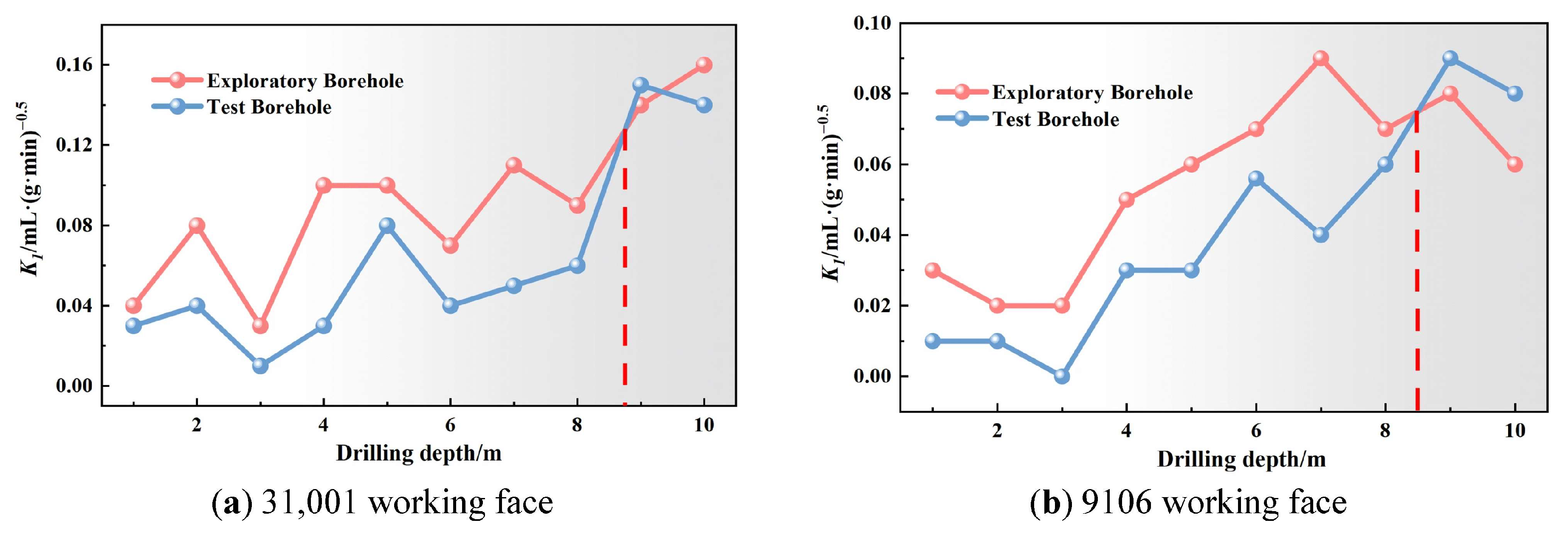
Figure 25 shows the measurement results of the drill cuttings gas desorption index (K1 value) at the No. 3 seam coal seam 31,001 and No. 9 coal seam 9106 working faces of Coal Seam 9 at Xinyuan Coal Mine. As the drilling depth increases, the K1 value generally exhibits a trend of initially decreasing and then increasing. Comparison of the variations in the K1 value between the observation and test boreholes during drilling indicated that after 2 h of gas discharge, the K1 value of the 76 mm diameter borehole began to exceed that of the observation borehole at a depth of 8.8 m. According to the calculation, the EDR of boreholes at the No. 3 coal seam 31,001 working face is 1.27 m. Similarly, the EDR for boreholes at the No. 9 coal seam 9106 working face is 1.23 m.
The K1 value of drill cuttings gas desorption primarily reflects the residual gas content within the coal [50]. As discussed previously, under mining influence, the coal ahead of the working face sequentially develops into stress relaxation, stress concentration, and original stress zones along the advance direction. Within the stress relaxation zone, the coal undergoes damage and fracturing owing to pressure relief, leading to the progressive development and interconnection of fracture networks [51], which significantly enhances the coal seam permeability, facilitating gas escape and resulting in relatively low residual gas content in this region. Consequently, during the initial stage of drilling (corresponding to the stress relaxation zone), the measured K1 value typically shows a downward trend. As drilling advances toward the stress concentration zone, the coal becomes compacted under high in situ stress, causing a substantial reduction in permeability and hindering gas migration [52]. This leads to increased residual gas content within the coal, which is indicated by a gradual increase in the K1 value of the drill cuttings gas desorption index with the increasing borehole depth.

3.4.3. Reliability Verification of the Numerical Model

To validate the field applicability of the established numerical model, a comparative analysis was conducted between the field-measured EDR values of the boreholes and the corresponding numerical simulation results. Considering the differences in the coal mechanical properties and seepage characteristics between the No. 3 coal seam 31,001 and No. 9 coal seam 9106 working faces at Xinyuan Coal Mine, the fundamental parameters of coal samples from both working faces were first determined through laboratory experiments prior to simulation. The results are presented in Table 4. By adjusting the relevant parameters in the numerical model, the EDR of the coal seam boreholes was simulated separately for the 31,001 and 9106 working faces.
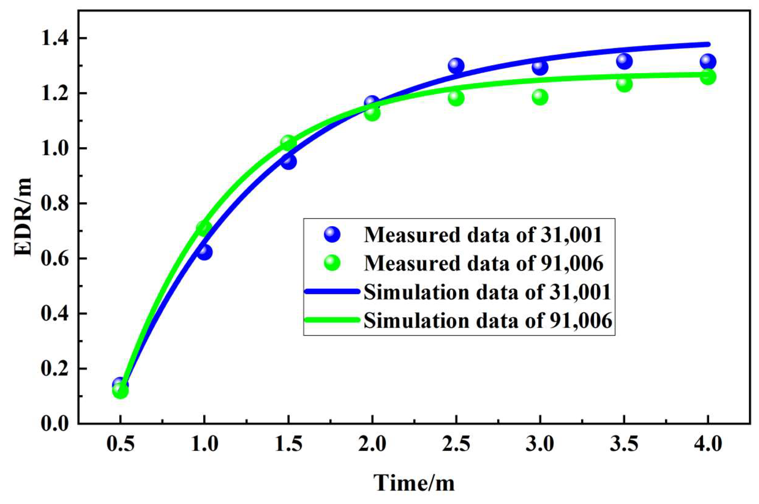
Figure 26 compares the field-measured EDR of the boreholes with the numerical simulation results. Overall, the temporal evolution trends of the EDR obtained from the field measurements and simulations are largely consistent. During the gas discharge process, the discrepancies between the field data and simulation results are relatively small. After 1, 2, 3 and 4 h of gas discharge, the errors for the 31,001 working face were 3.66%, 2.19%, 6.94% and 12.47%, respectively, while those for the 9106 working face were 2.85%, 3.49%, 12.38% and 5.56%, 1.37% respectively. Overall, the discrepancies between the field measurements and numerical simulation results for both the 31,001 and 9106 working faces remained below 15%, which generally satisfies the accuracy requirements for current engineering applications [53].

3.5. Field Application Results

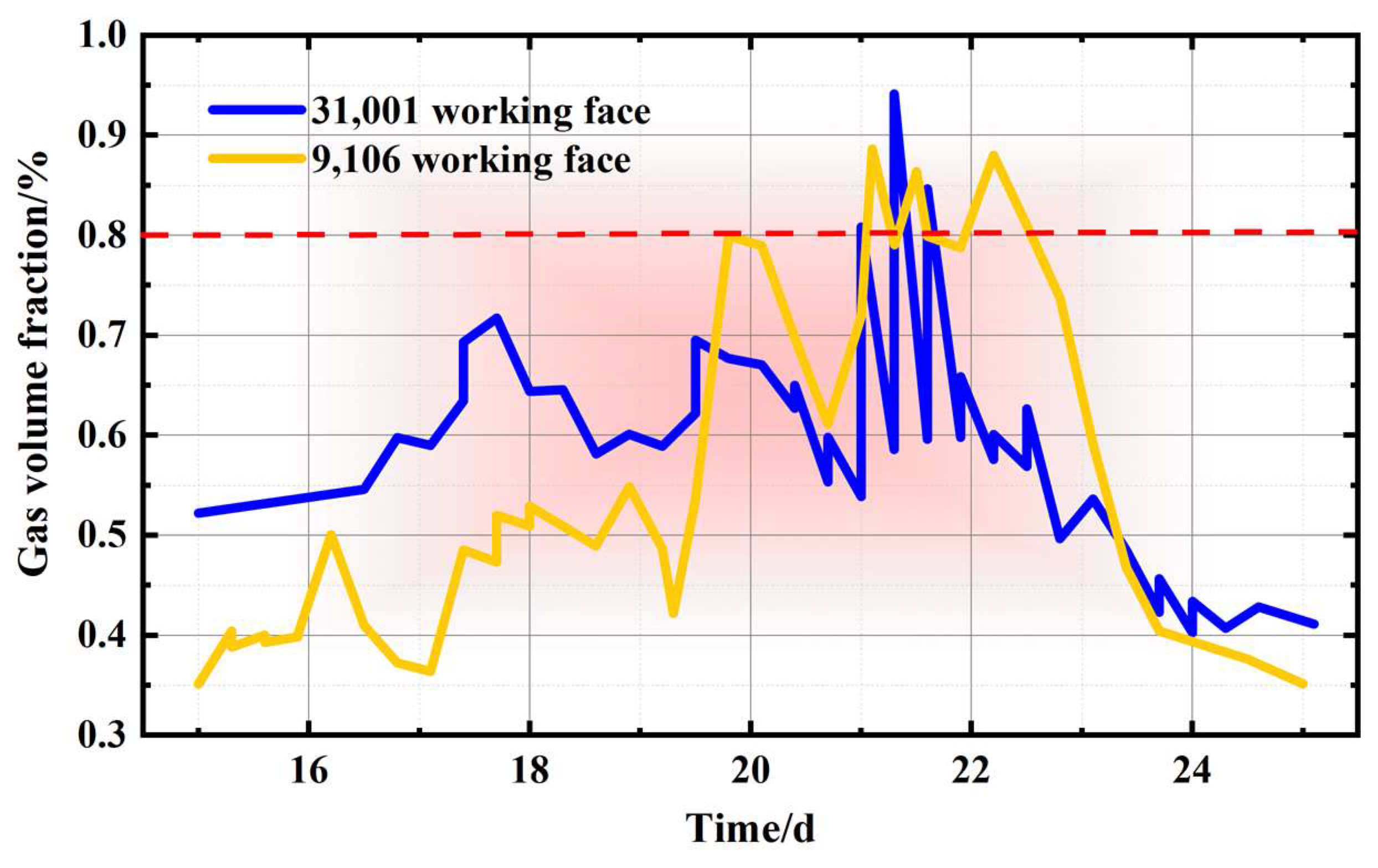
Figure 27 presents the monitoring results of the gas volume fraction at the upper corner of the No. 3 coal seam 31,001 and No. 9 coal seam 9106 working faces in late July 2025. The results indicate that on July 17, the gas volume fraction at the upper corner of the 31,001 working face exceeded the safety threshold of 0.6%. Subsequently, by adjusting the ventilation fan frequency, the gas volume fraction gradually decreased. However, on July 21, the gas volume fraction surged sharply and exceeded the warning threshold of 0.8%, necessitating immediate coal seam gas discharge operations. Meanwhile, on July 20, the gas volume fraction at the upper corner of the 9106 working face also reached the warning threshold of 0.8%. Both working faces subsequently initiated drilling operations for gas discharge.
Based on the experimental and simulation results, the drilling construction plan for the No. 3 coal seam 31,001 and No. 9 coal seam 9106 working faces at the Xinyuan coal mine is as follows: Two rows of square-pattern discharge boreholes are arranged in the central section of the coal seam within the mining face. A 15 m drilling-free zone is maintained at both the front and rear of the working face. Boreholes are positioned along soft stratification where possible. Drilling is conducted along the dip direction of the coal seam to a depth of 10 m, with a borehole diameter of 76 mm. The effective gas discharge duration is 5 h. Following gas discharge, the gas volume fraction at the upper corner of the working face gradually decreases to levels that permit safe coal mining, further validating the reliability of this study.

3.6. Borehole Layout Schemes Under Complex Geological Conditions

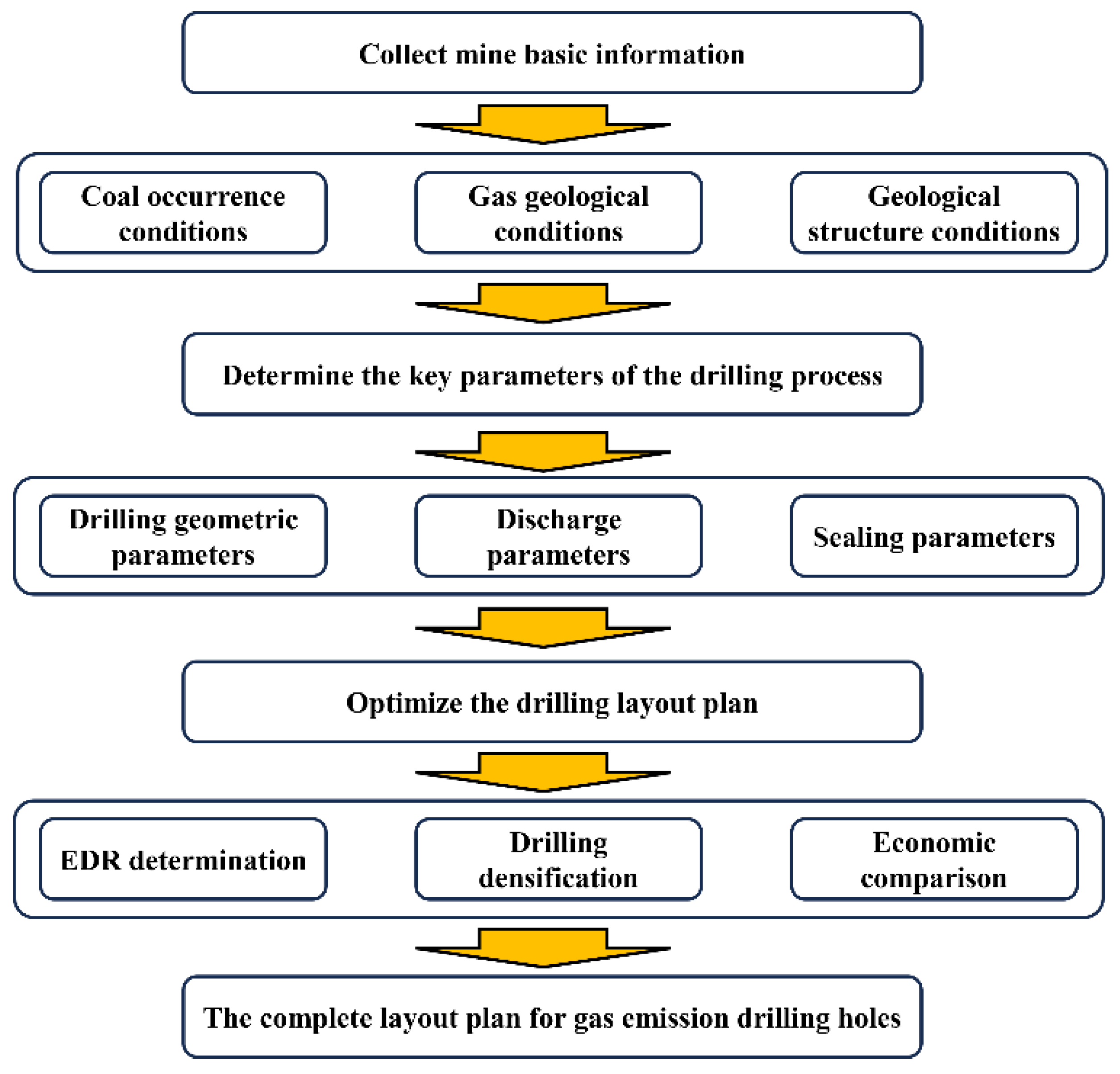
For the borehole layout problem under complex geological conditions such as soft coal seams, near fault zones, and sharp thickness variations, this study proposes a systematic design procedure. Firstly, basic geological data including coal seam occurrence, gas occurrence, geological structures, and in situ stress are collected to conduct a comprehensive evaluation and to delineate gas outburst hazard zones. Then, based on the geological evaluation results, key borehole parameters such as the borehole diameter, inclination angle, hole sealing, and extraction negative pressure are determined. Subsequently, the borehole layout scheme is checked and optimized from multiple dimensions including the extraction radius, geological structures, and engineering costs, with adjustments made to borehole spacing and horizon. Finally, a complete engineering scheme for gas discharge borehole layout is formulated, as shown in Figure 28.

4. Conclusions

The migration of coalbed methane into boreholes through seepage and its subsequent discharge into the atmosphere represent a typical fluid–solid coupling process. In this study, a fluid–solid coupled mathematical model for coalbed methane transport was established based on adsorption, seepage, and porous elasticity theories. The validity of the model was verified through comparison with field measurement results. Through mesh independence analysis, the optimal number of grid elements for the coal seam borehole model was determined to be 55,704. The main conclusions are as follows:
(1)
As the discharge time increases, the gas pressure around the borehole continuously decreases, and the affected zone expands elliptically outward. The EDR exhibits a power-law relationship with time. Increasing the borehole diameter progressively expands the EDR. During the first 3 h of gas discharge, increasing the borehole diameter accelerates the growth rate of the EDR; after 3 h of discharge, the growth rate slows and gradually stabilizes.
(2)
Coal seam permeability significantly influences the EDR. After 5 h of gas discharge, the EDR of a high-permeability coal seam (8 × 10⁻¹⁷ m2) is approximately twice that of a low-permeability coal seam (2 × 10⁻¹⁷ m2). When a multi-borehole drilling pattern is adopted, gas in the central region may form a blank zone owing to its distance from the boreholes. Coal seams drilled using a triple-flower pattern exhibit higher discharge efficiency within the first hour of gas discharge, whereas those drilled using a square pattern achieve a larger EDR after the first hour of discharge.
(3)
The S value (drill cuttings volume) and K1 value (drill cuttings gas desorption) respectively characterize the coal density and residual gas content. Field tests at the No. 3 coal seam 31,001 and No. 9 coal seam 9106 working faces of Xinyuan Coal Mine showed that both parameters initially decreased and then increased with the increasing borehole depth. This phenomenon results from the mining-induced redistribution of coal seam stress and gas pressure, which alters the coal body density and residual gas content, thereby driving variations in the S and K1 values.
(4)
The simulation results of the coal seam borehole model showed minimal deviation from field data during gas discharge. After 5 h of gas discharge using a square-pattern layout, the gas volume fraction at the upper corner of the No. 3 coal seam 31,001 and No. 9 coal seam 9106 working faces at Xinyuan Coal Mine decreased to levels permitting safe coal seam mining (0.6%).

Author Contributions

Conceptualization, C.L., Z.L., Z.D., K.R. and Y.B.; methodology, C.L., J.W., Z.L., Z.D. and K.R.; software, C.L., Z.L., Z.D. and K.R.; validation, J.W.; formal analysis, C.L., J.W., Z.L., Z.D. and K.R.; investigation, Z.L., Z.D. and K.R.; resources, J.W., Z.D. and K.R.; data curation, Z.D., K.R. and Y.B.; writing—review and editing, C.L. All authors have read and agreed to the published version of the manuscript.

Funding

This study was supported by the National Natural Science Foundation of China [No. 52074188].

Data Availability Statement

The original contributions presented in this study are included in the article. Further inquiries can be directed to the corresponding author.

Conflicts of Interest

Author Chong Liu was employed by the Shanxi Xinyuan Coal Limited Liability Company. The remaining authors declare that the research was conducted in the absence of any commercial or financial relationships that could be construed as a potential conflict of interest.

References

  1. Wang, E.; Zhang, G.; Zhang, C.; Li, Z. Research progress and prospect on theory and technology for coal and gas outburst control and protection in China. J. China Coal Soc. 2022, 47, 297–322. [Google Scholar] [CrossRef]
  2. Lin, B.; Yang, W.; Liu, T. Typical characteristics of deep coal seams with high outburst risk, outburst inducing mechanism and prevention measures. J. China Coal Soc. 2025, 50, 311–325. [Google Scholar] [CrossRef]
  3. Qiao, Z.; Li, C.; Wang, Q.; Xu, X. Principles of formulating measures regarding preventing coal and gas outbursts in deep mining: Based on stress distribution and failure characteristics. Fuel 2024, 356, 129578. [Google Scholar] [CrossRef]
  4. Liu, Z.; Song, C.; Ji, H.; Liu, S.; Tan, J.; Cheng, S.; Ning, F. Construction mode and key technology of mining shaft engineering for deep mineral resources. J. China Coal Soc. 2021, 46, 826–845. [Google Scholar] [CrossRef]
  5. Liu, Y.; Zhang, W.; Chen, C.; Wei, J.; Xu, X.; Zhang, H.; Nan, Q.; Xiao, P. Prospects for the development of the theory and technology of non-hydration penetration enhancement in soft coal seams. J. China Coal Soc. 2025, 50, 2123–2146. [Google Scholar] [CrossRef]
  6. Liang, Y.; Shi, B.; Yue, J.; Zhang, C.; Wang, C.; Han, Q. Gas seepage characteristics and discharge radius of coal seam borehole. Energy 2025, 335, 138020. [Google Scholar] [CrossRef]
  7. Zhang, J.; Wang, M.; Yuan, M.; Liu, Q.; Li, D.; Wang, X. Safe and green exploitation model and demonstration projects of deep outburst mine based on the integration of gas control, extraction and utilization. J. Chongqing Univ. 2022, 45, 29–40. [Google Scholar] [CrossRef]
  8. Zhai, H.; Linghu, J. Practice and mode of gas control technical innovation in Yangquan Mining Area. Coal Sci. Technol. 2018, 46, 168–175. [Google Scholar] [CrossRef]
  9. Liu, T.; Lin, B.; Fu, X.; Zhu, C. Modeling air leakage around gas extraction boreholes in mining-disturbed coal seams. Process Saf. Environ. Prot. 2020, 141, 202–214. [Google Scholar] [CrossRef]
  10. Liu, J.; Li, N.; Wu, J.; Yang, T. Temporal and spatial response of effective influence radius based on drainage borehole with different diameters. J. Saf. Sci. Technol. 2019, 15, 82–87. [Google Scholar] [CrossRef]
  11. Cheng, L.; Cheng, Z.; Lian, S.; Hao, D.; Wan, J. Study on effective discharge radius of advanced borehole with different diameters under time-space effect. J. Saf. Sci. Technol. 2021, 17, 72–76. [Google Scholar] [CrossRef]
  12. Zhou, A.; Li, J.; Gong, W.; Wang, K.; Du, C. Theoretical and numerical study on the contribution of multi-hole arrangement to coalbed methane extraction. Energy 2023, 284, 128598. [Google Scholar] [CrossRef]
  13. Qi, Q.; Qi, Y.; Zhang, J.; Zhou, X. Study on optimum drilling parameters for gas extraction in fully mechanized caving face. J. Saf. Sci. Technol. 2018, 14, 76–83. [Google Scholar] [CrossRef]
  14. Peng, S. Current status and prospects of research on geological assurance system for coal mine safe and high efficient mining. J. China Coal Soc. 2020, 45, 2331–2345. [Google Scholar] [CrossRef]
  15. Zhao, W.; Dong, H.; Yan, Z.; Wang, K.; Shu, L.; Feng, Z.; Lu, S.; Hu, K. Hierarchical occurrence law of gas content in deep coal seams and its relationship with outburst prevention. J. China Coal Soc. 2025, 50, 1555–1568. [Google Scholar] [CrossRef]
  16. Ma, S.; Wang, Z.; Qi, L.; Wang, L.; Chen, H. Determination on Effective Drainage Radius of In-Seam Borehole Based on Gas Content Test and Numerical Simulation Calculation Method. ACS Omega 2024, 9, 36485–36496. [Google Scholar] [CrossRef] [PubMed]
  17. Li, Q. Study on the Spatiotemporal Response Characteristics of Effective Discharge Radius of Bedding Drilling. Eng. Adv. 2023, 2, 198–200. [Google Scholar] [CrossRef]
  18. Zhang, T.; Jiang, X.; Bao, R.; Chen, J.; Fan, Y. Analysis on attenuation feature of gas flow in borehole passedthrough beds in high gassy mine. Coal Soc. Technol. 2018, 46, 74–79. [Google Scholar] [CrossRef]
  19. Wang, C.; Li, X.; Xu, C.; Niu, Y.; Chen, Y.; Yang, S.; Zhou, B.; Jiang, C. Study on factors influencing and the critical value of the drilling cuttings weight: An index for outburst risk prediction. Process Saf. Environ. Prot. 2020, 140, 356–366. [Google Scholar] [CrossRef]
  20. Liu, C.; Lu, Z.; Dong, Z.; Ren, K.; Ma, J.; Wang, J. Study on the law of disaster caused by multi-field coupling of coal and gas near fault tectonic zone. Int. J. Oil Gas Coal Technol. 2025, 1, 1. [Google Scholar] [CrossRef]
  21. Zou, Y.; Wang, W.; Fan, J.; Liu, P.; Li, Z.; Jiang, D. A dynamic model of coalbed methane emission from boreholes in front of excavation working face: Numerical model and its application. Environ. Sci. Pollut. Res. 2023, 30, 106276–106296. [Google Scholar] [CrossRef] [PubMed]
  22. Zhou, R.; Yan, B. Research on calculating gas pressure with gas flow in crossing borehole. Chin. J. Rock Mech. Eng. 2016, 35, 3147–3152. [Google Scholar] [CrossRef]
  23. Wang, C.; Liu, J. Determination method of prediction index and its critical value of coal and gas outburst. Xi’an Univ. Sci. Technol. 2015, 35, 567–572. [Google Scholar] [CrossRef]
  24. Shi, Y.; Lin, B.; Liu, T.; Liu, T.; Zhang, X.; Yang, W. Study on the influence of stress constraint conditions on multi-scale gas emission characteristics in in-situ coal. Energy 2024, 290, 130160. [Google Scholar] [CrossRef]
  25. Andrade, J.E.; Gu, Z.; Monfared, S.; Donald, K.A.M.; Ravichandran, G. Measuring Terzaghi’s effective stress by decoding force transmission in fluid-saturated granular media. J. Mech. Phys. Solids 2022, 165, 104912. [Google Scholar] [CrossRef]
  26. Liu, Z.; Hu, Z.; Zhu, W.; Zhao, T.; Liu, S.; Guo, Z.; Sun, C.; Bai, G. Effect of coal permeability evolution on CO2 storage capacity under phase partial pressure in ScCO2-ECBM processes. Energy 2024, 297, 131298. [Google Scholar] [CrossRef]
  27. Li, Z.; Yu, H.; Bai, Y.; Wang, Y.; Hu, H.; Gao, Y.; Yan, F. Analysis of reservoir permeability evolution and influencing factors during CO2-Enhanced coalbed methane recovery. Energy 2024, 304, 132045. [Google Scholar] [CrossRef]
  28. Fan, Y.; Deng, C.; Zhang, X.; Li, F.; Wang, X.; Qiao, L. Numerical study of CO2-enhanced coalbed methane recovery. Int. J. Greenh. Gas Control 2018, 76, 12–23. [Google Scholar] [CrossRef]
  29. Li, Z.; Yu, H.; Bai, Y.; Wang, Y.; Hu, H. Numerical study on the influence of temperature on CO2-ECBM. Fuel 2023, 348, 128613. [Google Scholar] [CrossRef]
  30. Zhao, L.; Ni, G.; Wen, Y.; Jiang, H.; Liu, Y.; Huang, Q.; Huang, W. Analysis of permeability evolution mechanism during CO2 enhanced coalbed methane recovery based on impact factor method. Fuel 2021, 304, 121389. [Google Scholar] [CrossRef]
  31. Zhang, L.; Jing, C.; Li, S.; Bao, R.; Zhang, T. Seepage Law of Nearly Flat Coal Seam Based on Three-Dimensional Structure of Borehole and the Deep Soft Rock Roadway Intersection. Energies 2022, 15, 5012. [Google Scholar] [CrossRef]
  32. Lu, Z.; Zhou, B.; Wang, J.; Chan, Z.; Yang, Q.; Dong, Z.; Dong, K. Study on the formation mechanism of a radon source during coal spontaneous combustion in a goaf. Fuel 2023, 336, 127135. [Google Scholar] [CrossRef]
  33. Xue, Y.; Wang, L.; Liu, Y.; Ranjith, P.G.; Cao, Z.; Shi, X.; Gao, F.; Kong, H. Brittleness evaluation of gas-bearing coal based on statistical damage constitution model and energy evolution mechanism. J. Cent. South Univ. 2025, 32, 566–581. [Google Scholar] [CrossRef]
  34. Li, K.; Zhu, L.; Xiong, F.; Liu, J.; Xue, Y.; Cao, Z.; Zhou, Y.; Liang, X.; Ji, M.; Liu, G.; et al. Review on Thermal Stimulation in Deep Geothermal Reservoirs: Thermo-Mechanical Mechanisms and Fracture Evolution. Processes 2026, 14, 1199. [Google Scholar] [CrossRef]
  35. Yin, G.; Li, X.; Zhao, H.; Li, X.; Li, G. In-situ experimental study on the relation of drilling cuttings weight to ground pressure and gas pressure. J. Univ. Sci. Technol. Beijing 2010, 32, 1–7. [Google Scholar] [CrossRef]
  36. Li, Q.; Wang, H.; Yuan, L.; Wang, W.; Hou, W.; Ma, Z.; Zhang, Q. Experimental study of damage and degradation of coal by adsorbed gas amount. J. China Univ. Min. Technol. 2019, 48, 955–965. [Google Scholar] [CrossRef]
  37. Bai, X.; Wang, D.; Tian, F.; Zhang, D.; Li, H.; Ren, F. Permeability model of damaged coal under triaxial stress loading-unloading. Chin. J. Rock Mech. Eng. 2021, 40, 1536–1546. [Google Scholar] [CrossRef]
  38. Zeng, F.; Wu, H.; Zhang, K.; Liu, Y. Fracture aperture evolution in subsurface fractured reservoirs: Insights from thermo-hydro-mechanical simulations and implications for field-scale applications. Int. J. Rock Mech. Min. Sci. 2025, 195, 106254. [Google Scholar] [CrossRef]
  39. Wu, L.; Dai, G.; Liu, Y.; Chen, Y.; Yang, D. Study on effective drainage radius of advance borehole based on gas flow theory. Coal Soc. Technol. 2013, 41, 64–66. [Google Scholar] [CrossRef]
  40. Yao, S.; Lu, P.; Zhu, Y. Experimental research on effective discharge radius in low permeability gassy Coal Seam. Coal Soc. Technol. 2014, 42, 146–148. [Google Scholar] [CrossRef]
  41. Lin, H.; Ji, P.; Kong, X.; Li, S.; Dou, G.; Li, K. Precise borehole placement model and engineering practice for pre-draining coal seam gas by drilling along seam. J. China Coal Soc. 2022, 47, 1220–1234. [Google Scholar] [CrossRef]
  42. Duan, M.; Lu, M.; Yang, K.; Ban, R.; Hu, X.; Jiang, C.; Lyu, X. Gas drainage and optimal arrangement of boreholes based on permeability anisotropy. Geomat. Nat. Hazards Risk 2023, 14, 2272573. [Google Scholar] [CrossRef]
  43. Zhang, C.; Xu, J.; Peng, S.; Li, Q.; Yan, F. Experimental study of drainage radius considering borehole interaction based on 3D monitoring of gas pressure in coal. Fuel 2019, 239, 955–963. [Google Scholar] [CrossRef]
  44. Li, Q.; Wang, Z.; Ma, S.; Zhao, X. Spatiotemporal response characteristics of effective extractionradius of bedding drilling. Coal Eng. 2025, 57, 1–6. [Google Scholar] [CrossRef]
  45. Cui, N.; Li, Z.; Pan, Y. Study on index of drilling bits for coalbed rockburst influenced by gas. J. Liaoning Tech. Univ. 2006, 2, 192–193. [Google Scholar] [CrossRef]
  46. He, F.; Li, L.; Lv, K.; Qin, B.; Xu, X.; Ma, Q.; Chen, Y. Study on evolution of front abutment pressure at working face in repeated mining of close-distance coal seams. Sustainability 2022, 14, 12399. [Google Scholar] [CrossRef]
  47. Xu, C.; Qin, L.; Wang, K.; Wu, S.; Zhang, R.; Guo, H.; Shu, L. Deformation and failure characteristics of gas drainage drilling-reaming coal mass in non-uniform stress field. J. China Coal Soc. 2023, 48, 1538–1550. [Google Scholar] [CrossRef]
  48. Yang, L.; Gao, F.; Wang, X.; Li, J. Energy evolution law and failure mechanism of coal-rock combined specimen. J. China Coal Soc. 2019, 44, 3894–3902. [Google Scholar] [CrossRef]
  49. Guo, Y.; Zhou, H.; Rong, T.; Wang, L.; Zhong, J.; Ren, W.; Chen, Z. Disturbance characteristics of deep coal mass under the mining stress path. J. China Coal Soc. 2018, 43, 3072–3079. [Google Scholar] [CrossRef]
  50. Lei, H. Experimental study on rapid determination of critical value of drilling cutting gas desorption index K1. Coal Soc. Technol. 2019, 47, 129–134. [Google Scholar] [CrossRef]
  51. Lei, G.; Li, C.; Cui, C.; Wang, J.; Li, X.; Yuan, H.; Liu, H. Dynamic evolution and damage fracture characteristics of coal mass during confining pressure unloading. J. Min. Strat. Control Eng. 2025, 7, 93–104. [Google Scholar] [CrossRef]
  52. Liu, X.; Sang, S.; Zhou, X.; Wang, Z. Coupled adsorption-hydro-thermo-mechanical-chemical modeling for CO2 sequestration and well production during CO2-ECBM. Energy 2023, 262, 125306. [Google Scholar] [CrossRef]
  53. Dong, Z.; Liu, A.; Qi, Q.; Yu, W.; Teng, G. Research on dynamic numerical simulation of gas emission and coal spontaneous combustion in stope. China Saf. Sci. J. 2017, 27, 30–35. [Google Scholar] [CrossRef]
Figure 1. Elastic damage evolution of coal.
Processes 14 02212 g001
Figure 2. Schematic illustrating the process of determining the EDR.
Processes 14 02212 g002
Figure 3. Numerical simulation process of coal seam drilling hole methane discharge.
Processes 14 02212 g003
Figure 4. Grid-independent verification.
Processes 14 02212 g004aProcesses 14 02212 g004b
Figure 5. Changes in gas pressure during drilling gas discharge.
Processes 14 02212 g005
Figure 6. Changes in gas pressure ahead of the coal seam during drilling and gas discharge.
Processes 14 02212 g006
Figure 7. Changes in gas pressure along monitoring line a during gas discharge.
Processes 14 02212 g007
Figure 8. Damage evolution during drilling gas discharge.
Processes 14 02212 g008
Figure 9. Variation in EDR of boreholes at different time points.
Processes 14 02212 g009
Figure 10. Variations in gas pressure within coal seams at different borehole diameters on monitoring plane 1.
Processes 14 02212 g010
Figure 11. Effect of borehole diameter on methane discharge from boreholes.
Processes 14 02212 g011
Figure 12. Damage evolution at different borehole diameters.
Processes 14 02212 g012
Figure 13. Variation in EDR at different borehole diameters.
Processes 14 02212 g013
Figure 14. Changes in gas pressure within coal seams under different permeability conditions.
Processes 14 02212 g014
Figure 15. Effect of coal seam permeability on drillhole gas discharge.
Processes 14 02212 g015
Figure 16. Damage evolution at different coal seam permeabilities.
Processes 14 02212 g016
Figure 17. Variation in EDR under different coal seam permeabilities.
Processes 14 02212 g017
Figure 18. Commonly used borehole layout methods in underground coal mines.
Processes 14 02212 g018
Figure 19. Variations in gas pressure within coal seams under different drilling patterns.
Processes 14 02212 g019
Figure 20. Changes in gas pressure ahead of the coal seam.
Processes 14 02212 g020
Figure 21. Effect of borehole arrangement on borehole gas discharge.
Processes 14 02212 g021
Figure 22. Damage evolution at different pore distribution patterns.
Processes 14 02212 g022
Figure 23. Variation in EDR at different pore distribution patterns.
Processes 14 02212 g023
Figure 24. Field measurement results of cuttings volume (S value) during drilling operations.
Processes 14 02212 g024
Figure 25. Field measurement results of drill cuttings gas desorption (K1 value) during drilling operations.
Processes 14 02212 g025
Figure 26. Comparison of field measurements and numerical simulation results.
Processes 14 02212 g026
Figure 27. Monitoring results of gas volume fraction at the upper corner of the working face.
Processes 14 02212 g027
Figure 28. Engineering scheme for gas discharge borehole layout.
Processes 14 02212 g028
Table 1. Basic parameters of the numerical model.
ParameterValue
Modulus of elasticity of coal2713 MPa
Poisson’s ratio0.345
Density of coal1300 kg/m3
Initial porosity of coal seam0.057
Initial permeability of coal seam7.42 × 10−17 m2
Initial temperature of the coal seam293.15 K
Initial gas pressure in coal fractures1.56 MPa
Initial gas pressure in the coal matrix1.56 MPa
Gas diffusion coefficient3.48 × 10−11 m2/s
Dynamic viscosity of gas1.03 × 10−5 Pa·s
Langmuir pressure constant of gas2.07 MPa
Langmuir volume constant of gas0.0256 m3/kg
Table 2. Simulation schemes.
Simulation
Number
Key ParameterThe Distance Between EDR and the Center of the Borehole
Elastic Modulus/EPoisson’s Ratio/vGas Diffusion
Coefficient/D
128000.252 × 10−101.38
228000.34 × 10−101.93
328000.356 × 10−102.38
432000.254 × 10−102.18
532000.36 × 10−102.63
632000.352 × 10−101.78
736000.256 × 10−102.88
836000.32 × 10−102.03
936000.354 × 10−102.58
Table 3. The results of the variance analysis.
Key ParameterSum of Squared DeviationsDegree of
Freedom
Mean SquareF Valuep ValueSignificance
Elastic modulus/E0.54120.270552.040.019*
Poisson’s ratio/v0.01520.00751.440.410non-significant
Gas diffusion
Coefficient/D
1.22120.6105117.400.008**
Error0.010420.0052   
SUM1.7878    
*: Significant; **: Highly significant.
Table 4. Basic parameters of coal samples from different coal seams.
No. 3 Coal SeamNo. 9 Coal Seam
Modulus of elasticity of coal2713 MPa3513 MPa
Poisson’s ratio0.3450.332
Density of coal1300 kg/m32250 kg/m3
Initial porosity of coal seam0.0570.042
Initial permeability of coal seam7.42 × 10−17 m28.13 × 10−17 m2
Initial temperature of coal seam293.15 K293.15 K
Disclaimer/Publisher’s Note: The statements, opinions and data contained in all publications are solely those of the individual author(s) and contributor(s) and not of MDPI and/or the editor(s). MDPI and/or the editor(s) disclaim responsibility for any injury to people or property resulting from any ideas, methods, instructions or products referred to in the content.