CO2 Trapping Mechanisms in Geological Carbon Sequestration: A Critical Review of Multiscale Processes and Storage Security


Abstract
1. Introduction
- (a)
- Geological CCS: Geological CCS involves capturing CO2 from various industrial sources and storing it in underground formations. The practice usually involves injecting supercritical CO2 into porous rock formations such as saline aquifers, unusable coal seams, depleted oil and gas fields, and basalt formations [9]. Also, CO2 is typically injected at depths greater than 3000 feet in presence of caprocks that seal the formations [10].
- (b)
- Biological CCS: This involves the storage of CO2 in vegetation on land and in waterbodies, soils, and wetlands. For instance, trees and vegetation can absorb CO2 and use it during the process of photosynthesis. Similarly sustainable agricultural practices such as no-till farming and cover cropping can significantly improve carbon sequestration.
- i.
- CO2 Capture: CO2 is captured from large point sources such as power plants, natural gas processing facilities, cement factories, and steel mills. CO2 capture is performed through three different mechanisms which are as follows:
- (a)
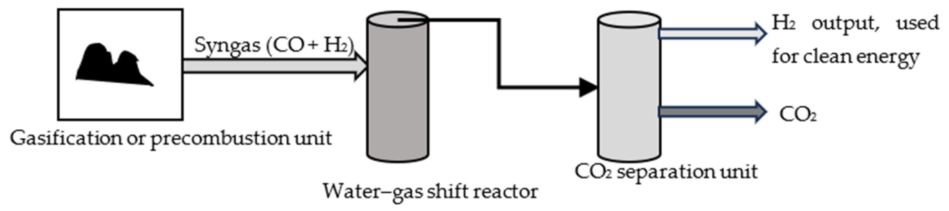
- Pre-combustion capture: CO2 is captured before combustion by converting fuel to a synthetic gas mixture (syngas) and CO2 is separated after a chemical reaction. Figure 1 shows a diagram of pre-combustion capture of CO2.Fossil fuels are converted to syngas (synthetic gas) through incomplete combustion. Syngas is a mixture of CO and H2 and it undergoes a water–gas shift reaction to produce CO2 and H2, following which CO2 is separated from H2 using physical or chemical reactions.
- (b)
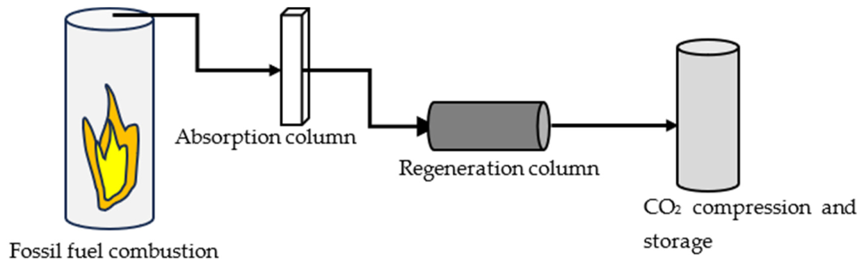
- Post-combustion capture: CO2 is captured after fuel is burned; it is separated from the flue gas using membranes, chemical solvents, and solid sorbents. As part of this process, fossil fuels are burned in air to produce flue gases containing CO2, N2, water vapor, O2, and other pollutants. After the hot flue gas is cooled, particulates and other pollutants are removed from it. The cooled flue gas passes through an absorption column where it reacts with the solvent to produce a weakly bonded compound. Next, CO2-rich solvent is heated in a regeneration column releasing pure CO2 gas. Figure 2 shows post-combustion CO2 capture.
- (c)
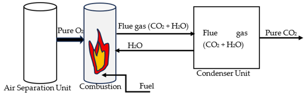
- Oxy-fuel combustion capture, where CO2 is captured during combustion. As part of this process, fuel is burned in pure oxygen instead of air and it produces CO2 and water vapor. While water is condensed, CO2 is captured. Figure 3 shows a diagram of oxy-fuel combustion CO2 capture process.
- ii.
- CO2 Compression and Transport:
- iii.
- CO2 Sequestration:
1.1. Review Methodology
- Identification: At this stage, the objective was to identify an area of carbon capture and sequestration that was not adequately explored in the current body of knowledge. The main keywords for the literature survey were determined, which were related to CO2 sequestration and subsurface CO2 trapping mechanisms. Some examples of the keywords identified for the search were “carbon sequestration”, “carbon capture and storage (CCS)”, “structural trapping”, “mineralization”, “residual trapping”, “capillary trapping”, and “solubility trapping”. The identified keywords were then used to search for articles on databases such as ScienceDirect, Wiley Online Library, SpringerLink, the American Chemical Society, and OnePetro, which is managed by Society of Petroleum Engineers (SPE). In addition, the keywords were also entered on ‘Google Scholar’ to review a large spectrum of journal articles, conference papers, and book chapters that dealt with the areas of interest. The time range for the web search was between April 2025 and May 2026.
- Screening: All articles gathered through the search were screened by carefully reading the titles and abstracts. Therefore, the articles that were not aligned with the scope of review were discarded.
- Eligibility: At this time, a secondary-level assessment was conducted and the articles selected after the initial screening were reviewed by reading through results, discussions, and conclusions. Only those articles that discussed CO2 trapping mechanisms were selected for review.
- Inclusion and Analysis: At this stage, the manuscripts that passed the eligibility criteria were included and subsequent analyses were performed to identify trends, projections, or any knowledge gaps.
- Preparation of Manuscript: The manuscript was carefully prepared with the aim of providing an overview of the established CO2 trapping mechanisms, summarizing some of the latest developments reported by researchers in recent years, and evaluating any knowledge gaps to direct future researchers. Finally, each trapping mechanism was evaluated for their current technology readiness level based on the available evidence.
1.2. Objectives and Novelty of the Review
2. Mechanisms of CO2 Trapping
2.1. Structural or Stratigraphic Trapping
- (a)
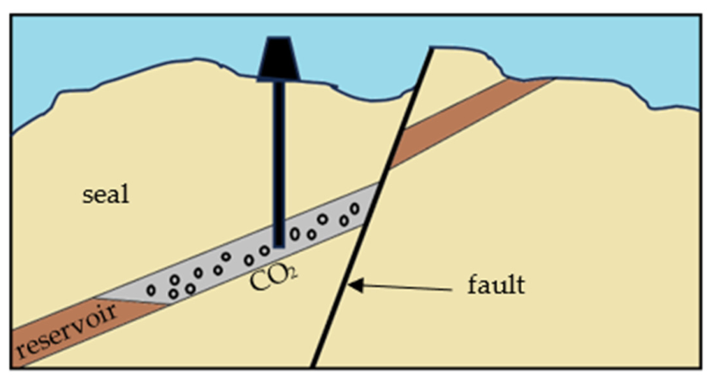
- Cataclastic fault seals: These are formed from pure sandstones with low clay content. These are formed due to the mechanical crushing, grinding, and fracturing of rocks during fault movement.
- (b)
- Cement seals: These are formed through the precipitation of minerals that fill in the pore spaces and therefore block fluid flow.
- (c)
- Juxtaposition seals: These types of seals are formed when fault movement causes different rock layers to be juxtaposed or placed next to each other. When the rock layer on one side of the fault is permeable, the layer on the other side is impermeable. So, the impermeable rock acts as a barrier to the flow.
- (d)
- Phyllosilicate fault seals: These are seals formed through the deformation of fault seals that are rich in phyllosilicate materials such as clay, chlorite, smectite, serpentine, etc. The fault zone becomes concentrated with these materials and its permeability is reduced.
- (e)
- Clay smears: These are formed when the faulting process deforms clay units within the fault zone. Therefore, a low permeability clay layer is formed.
- (a)
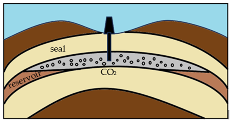
- Anticlines: These are upward-arching folds with rock layers bending upwards like an inverted bowl. As buoyant CO2 migrates upwards through the porous rock, they are trapped at the crest of the anticline. An overlying impermeable caprock prevents CO2 from escaping.
- (b)
- Domes: These are special types of anticlines with elliptical or circular cross-sections. They are completely closed from all directions.
2.2. Mineralization
2.2.1. Direct Carbonation
- (i)
- Leaching of minerals: During this process, metal ions such as Ca2+ and Mg2+ are extracted from the solid mineral into the aqueous phase such that they can react with the carbonate ions to form solid carbonates. The following is an example of leaching.Mg2SiO4 (s)+ 4 H+(aq) → 2Mg+2 (aq)+ 2H2O (l) + SiO2 (s)
- (ii)
- Release of carbonate ions: CO2 reacts with liquid water to release carbonate atoms:CO2 (g) + H2O (l) CO32− (aq) + 2H+ (aq)CO2 (g) + H2O (l) → CO32− (aq) + 2H+ (aq)
- (iii)
- Formation of carbonate atoms: During this step, the nucleation and the growth of mineral carbonates take place.Mg2+ (aq) + CO32− (aq) → MgCO3 (s)
- (a)
- (b)
- Addition of other organic acids: A combination of oxalic acid, ethylenediaminetetraacetic acid, and orthophosphoric acid is known to increase dissolution rates of Mg2SiO4 [24].
- (c)
- Addition of alkali metal hydroxides: An addition of alkali metal hydroxides increases pH within the solution and enhances absorption of CO2 [20].
- (d)
- Addition of sodium carbonate: Dissolution of Mg2SiO4 can be enhanced by raising its pH and by adding Na2CO3 [25].
2.2.2. Indirect Carbonation
2.2.3. Economic Implications Associated with Mineralization
2.3. Solubility Trapping
2.4. Residual (Capillary)Trapping
Economic Implications Associated with Residual Trapping
3. Recent Advances in CO2 Trapping Technologies
3.1. Dominance of Trapping Mechanisms at Different Time Scales
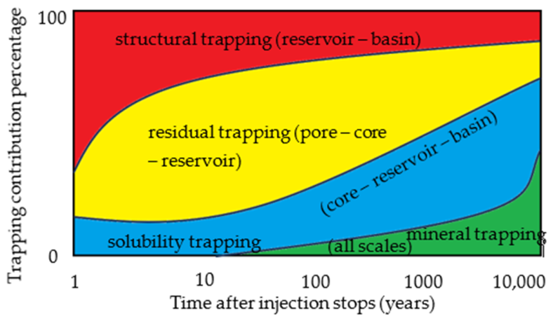
- Injection Phase (days to years): At this stage, the most dominant trapping mechanisms are structural trapping and residual trapping. While structural trapping begins with immediate accumulation of CO2 beneath caprock due to buoyancy, residual trapping begins concurrently as CO2 displaces brine and starts building immobile fractions [63].
- Early Post-injection Phase (1–50 years): During this stage, although structural trapping still controls global containment boundaries, residual trapping develops over months to years as soon as injection stops [63].
- Intermediate phase (50–100 years): A recent numerical study suggested that residual or capillary trapping dominates solubility trapping over time. For instance, residual trapping volumes may be twice the solubility trapping volumes after approximately 50 years. However, it is estimated that immediately after the injection phase, solubility trapping may be able to trap more volumes than residual trapping [64]. This suggests that residual trapping is not simply a short-term mechanism. It evolves and strengthens over time and depends on the microstructure and flow-regime. Contradictory to this article, another recent study reported solubility trapping along with mineralization as the most dominant trapping mechanisms during this stage [65].
- Long-term Phase (>100 years–1000 years): Mineralization or mineral trapping is the most dominant trapping mechanism in the long term [66].
3.2. Evidence of Pore-Scale Experimental Observations Translating to Field-Scale
- (a)
- Residual Trapping is a Scalable, Dominant Mechanism: Pore-scale imaging such as micro-CT has revealed that CO2 becomes immobilized as disconnected ganglia due to capillary forces. These observations are consistently observed from pore to field scale [32]. Residually trapped CO2 in the form of droplets, ganglia, and connected networks strongly affect flow behavior and trapping efficiency. With increase in pressure, there is more droplet formation, and it improves residual saturation. However, with increase in temperature, droplet formation increases but residual saturation decreases. Therefore, in addition to the amount of CO2, the morphology and topology of CO2 govern residual trapping efficiency [67].
- (b)
- Pore-scale Flow Regimes Predict Plume Migration Patterns: Viscous fingering, snap off, and heterogeneity govern trapping efficiency. At low capillary numbers, viscous fingering produces preferential flow paths and limits the efficiency of sweeping. Also, snap-off in small pore throats enhances residual trapping [68].
- (c)
- Mapping of Pore Variables to Storage Efficiency: Recently published research articles reported the importance of variables such as wettability, capillary pressure, heterogeneity, and salinity towards improving model reliability and accurate assessment of storage efficiency. The following is some evidence that has been provided:
- Wettability: Recent experiments in limestone show that residual trapping drops as rocks become CO2 wet. Rocks wetted by CO2 provide continuous wetting layers offering flow pathways, thus preventing residual trapping. Results showed that while water-wet rocks enabled more than 20% residual saturation, CO2-wet rocks were associated with 8% saturation only [69].
- Gravity: Another recent article reported that downward (gravity-assisted) imbibition resulted in more fragmentation and therefore, higher residual trapping [74].
- (d)
- Interdependence of Residual and Solubility Trapping Mechanisms
- (e)
- Strategies for Accelerating Mineralization
- (f)
- Factors Affecting Structural Trapping
4. Influence of Uncertainty in Pore Variables on Model Reliability
5. Technology Readiness Levels of CO2 Trapping Mechanisms
- (a)
- Observability (2 points): If direct measurement technologies are available, then the mechanism receives more TRL points. Likewise, inferred behaviors receive less points.
- (b)
- Scale Validation (2 points): If a mechanism is restricted to pore or core scales only, they receive less points. Reservoir or basic scale demonstrations are assigned more points.
- (c)
- Predictive Capabilities (2 points): If the outcomes through a trapping mechanism can be reliably forecasted, then it receives more points, while a higher degree of uncertainty results in less points.
- (d)
- Deployment Reliance (3 points): If a mechanism is being actively used in the field, then it receives maximum points using this criterion. If the mechanism can be reliably tested only in the long term, then it receives less points.
6. Environmental Implications
- CO2 Leakage Risks: One of the most important environmental concerns is the possibility of CO2 leakage back into the atmosphere owing to caprock failure, or through potential leakage pathways such as faults and fractures.
- Groundwater Contamination: Groundwater quality can be impacted by the leakage of brine or CO2 into groundwater resources [84,85,86,87]. Researchers established that CO2 infiltrating an unconfined freshwater aquifer at atmospheric pressure and under oxidizing conditions can lower pH and increase the concentration of dissolved solids such as Al, Mn, Fe, Zn, Cd, Se, Ba, and U [88]. Therefore, the leakage of CO2 or brine can compromise the quality of potable water resources, rendering them unsuitable for human consumption.
- Induced Seismicity: Injection of large volumes of CO2 can change pore pressure, which may cause deformation or fracture. In addition, this may also reactivate faults and induce seismicity [89,90,91]. Although induced seismicity is a serious concern, researchers conclude that careful project design and meticulous site selection is the key to mitigating the risks [92].
- Brine Displacement: CO2 injection at large pressure gradients can cause brine to move upwards and infiltrate into freshwater aquifers. This can cause high salt concentrations or increase the concentration of toxic elements in water. Therefore, intrusion of brine in underground drinking water sources is a major risk [93].
7. Conclusions
Author Contributions
Funding
Data Availability Statement
Acknowledgments
Conflicts of Interest
Abbreviation
| TRL | Technology Readiness Level |
References
- Climate Change: Global Temperature. Available online: https://www.climate.gov/news-features/understanding-climate/climate-change-global-temperature (accessed on 23 April 2025).
- Fagorite, V.I.; Onyekuru, S.O.; Opara, A.I. The major techniques, advantages, and pitfalls of various methods used in geological carbon sequestration. Int. J. Environ. Sci. Technol. 2023, 20, 4585–4684. [Google Scholar]
- Nanda, S.; Reddy, S.N.; Mitra, S.K.; Kozinski, J.A. The progressive routes for carbon capture and sequestration. Energy Sci. Eng. 2016, 4, 99–122. [Google Scholar] [CrossRef]
- Arora, G. Causes and effects of global warming. Eur. J. Mol. Clin. Med. 2020, 7, 947–953. [Google Scholar]
- Al-Ghussain, L. Global warming: Review on driving forces and mitigation. Environ. Prog. Sustain. Energy. 2019, 38, 13–21. [Google Scholar]
- Roul, M.K.; Mishra, R.; Das, A. Impact of increase in greenhouse gases on global warming and its remedies. J. Emerg. Technol. Innov. Res. 2017, 4, 981–986. [Google Scholar]
- Watson, R.T.; Zinyowera, M.C.; Moss, R.H. Climate Change 1995: Impacts, Adaptations and Mitigation of Climate Change; Cambridge Univ. Press: New York, NY, USA, 1996. [Google Scholar]
- Raven, J.; Caldeira, K.; Elderfield, H.; Hoegh-Guldberg, O.; Liss, P.; Riebesell, U.; Watson, A. Ocean Acidification Due to Increasing Atmospheric Carbon Dioxide; The Royal Society: London, UK, 2005. [Google Scholar]
- Ask MIT Climate. Available online: https://climate.mit.edu/ask-mit/what-risk-co2-stored-underground-after-carbon-capture-will-escape-again (accessed on 24 April 2025).
- Kaldi, J.; Daniel, R.; Tenthorey, E.; Michael, K.; Schact, U.; Nicol, A.; Underschultz, J.; Backe, G. Containment of CO2 in CCS: Role of Caprocks and Faults. Energy Procedia 2013, 37, 5403–5410. [Google Scholar] [CrossRef]
- Wang, D.; Li, J.; Lian, W.; Liu, X.; Zhang, J.; Yang, H.; Guo, S. Impact of CO2 sequestration on pressure systems in saline aquifer: Simulation of differential pressure evolution in the caprock-reservoir. Geoenergy Sci. Eng. 2024, 236, 212748. [Google Scholar] [CrossRef]
- Meng, X.; Kooijman, A.M.; Temme, A.J.; Cammeraat, E.L. The current and future role of biota in soil-landscape evolution models. Earth-Sci. Rev. 2022, 226, 103945. [Google Scholar] [CrossRef]
- Szulczewski, M.L.; Hesse, M.A.; Juanes, R. Carbon dioxide dissolution in structural and stratigraphic traps. J. Fluid Mech. 2013, 736, 287–315. [Google Scholar] [CrossRef]
- Massarweh, O.; Abushaikha, A.S. CO2 sequestration in subsurface geological formations: A review of trapping mechanisms and monitoring techniques. Earth-Sci. Rev. 2024, 253, 104793. [Google Scholar] [CrossRef]
- Ali, M.; Jha, N.K.; Pal, N.; Keshavarz, A.; Hoteit, H.; Sarmadivaleh, M. Recent advances in carbon dioxide geological storage, experimental procedures, influencing parameters, and future outlook. Earth-Sci. Rev. 2022, 225, 103895. [Google Scholar] [CrossRef]
- Knipe, R.J. Juxtaposition and seal diagrams to help analyze fault seals in hydrocarbon reservoirs. AAPG Bull. 1997, 81, 187–195. [Google Scholar] [CrossRef]
- Iglauer, S. Optimum storage depths for structural CO2 trapping. Int. J. Greenh. Gas Control. 2018, 77, 82–87. [Google Scholar] [CrossRef]
- Zhang, S.; DePaolo, D.J. Rates of CO2 mineralization in geological carbon storage. Acc. Chem. Res. 2017, 50, 2075–2084. [Google Scholar] [CrossRef] [PubMed]
- Ju, Y.; Wang, G.; Li, S.; Sun, Y.; Suo, Y.; Somerville, I.; Yu, K. Geodynamic mechanism and classification of basins in the Earth system. Gondwana Res. 2022, 102, 200–228. [Google Scholar] [CrossRef]
- Yadav, S.; Mehra, A. A review on ex situ mineral carbonation. Environ. Sci. Pollut. Res. 2021, 28, 12202–12231. [Google Scholar] [CrossRef]
- Khan, M.N.; Siddiqui, S.; Thakur, G.C. Recent advances in geochemical and mineralogical studies on CO2–brine–rock interaction for CO2 sequestration: Laboratory and simulation studies. Energies 2024, 17, 3346. [Google Scholar]
- Menefee, A.H.; Li, P.; Giammar, D.E.; Ellis, B.R. Roles of transport limitations and mineral heterogeneity in carbonation of fractured basalts. Environ. Sci. Technol. 2017, 51, 9352–9362. [Google Scholar] [CrossRef] [PubMed]
- Lackner, K.S. Carbonate chemistry for sequestering fossil carbon. Annu Rev. Energy Environ. 2002, 27, 193–232. [Google Scholar] [CrossRef]
- Park, A.H.A.; Jadhav, R.; Fan, L.S. CO2 mineral sequestration: Physically activated dissolution of serpentine and pH swing process. Chem. Eng. Sci. 2003, 59, 5241–5247. [Google Scholar]
- Huijgen, W.J.J.; Comans, R.N.J. Carbon Dioxide Sequestration by Mineral Carbonation, Literature Review; Report number: ECN-C–03-016; Energy Research Centre of the Netherlands (ECN): Sint Maartensvlotbrug, The Netherlands, 2007. [Google Scholar]
- Balashov, V.N.; Guthrie, G.D.; Hakala, J.A.; Lopano, C.L.; Rimstidt, J.D.; Brantley, S.L. Predictive modeling of CO2 sequestration in deep saline sandstone reservoirs: Impacts of geochemical kinetics. Appl. Geochem. 2013, 30, 41–56. [Google Scholar] [CrossRef]
- Anderson, J.; Bachu, S.; Nimir, H.B.; Basu, B.; Bradshaw, J.; Deguchi, G.; Zhou, D. Underground Geological Storage; Cambridge University Press: Cambridge, UK, 2005. [Google Scholar]
- Leslie, R.; Cavanagh, A.J.; Haszeldine, R.S.; Johnson, G.; Gilfillan, S.M. Quantification of solubility trapping in natural and engineered CO2 reservoirs. Pet. Geosci. 2021, 27, petgeo2020-120. [Google Scholar] [CrossRef]
- Mykkeltvedt, T.S.; Sandve, T.H.; Gasda, S.E. New Sub-grid Model for Convective Mixing in Field-Scale CO2 Storage Simulation. Transp. Porous Media 2025, 152, 9. [Google Scholar]
- Mingotti, N.; Woods, A.W. Convective dissolution of capillary-trapped carbon dioxide. Commun. Earth Environ. 2025, 6, 570. [Google Scholar] [CrossRef]
- Wang, Y.; Fernàndez-Garcia, D.W.; Saaltink, M. Numerical analysis of the effect of heterogeneity on CO2 dissolution enhanced by gravity-driven convection. Hydrol. Earth Syst. Sci. 2025, 29, 2485–2503. [Google Scholar] [CrossRef]
- Krevor, S.; Blunt, M.J.; Benson, S.M.; Pentland, C.H.; Reynolds, C.; Al-Menhali, A.; Niu, B. Capillary trapping for geologic carbon dioxide storage–From pore scale physics to field scale implications. Int. J. Greenh. Gas Control 2015, 40, 221–237. [Google Scholar]
- Saadatpoor, E.; Bryant, S.L.; Sepehrnoori, K. New trapping mechanism in carbon sequestration. Transp. Porous Media 2010, 82, 3–17. [Google Scholar]
- Ruprecht, C.; Pini, R.; Falta, R.; Benson, S.; Murdoch, L. Hysteretic trapping and relative permeability of CO2 in sandstone at reservoir conditions. Int. J. Greenh. Gas Control 2014, 27, 15–27. [Google Scholar] [CrossRef]
- Grigg, R.B.; Svec, R.K. CO2 transport Mechanisms in CO2/brine coreflooding. In Proceedings of the SPE Annual Technical Conference and Exhibition, San Antonio, TX, USA, 24–27 September 2006. [Google Scholar]
- Burnside, N.M.; Naylor, M. Review and implications of relative permeability of CO2/brine systems and residual trapping of CO2. Int. J. Greenh. Gas Control 2014, 23, 1–11. [Google Scholar] [CrossRef]
- Magzymov, D.; Jerauld, G.; Lyons, E.; Richardson, S.; Lun, L. Is There Unusual Hysteresis Between Primary Drainage and Imbibition Relative Permeability for Supercritical Carbon Dioxide? In Proceedings of the SPE Annual Technical Conference and Exhibition, New Orleans, LA, USA, 23–25 September 2024. [Google Scholar]
- Sharifigaliuk, H.; Mahmood, S.M.; Zoveidavianpoor, M.; Zivar, D.; Ayobami Afolabi, F. Experimental and modeling study of water imbibition and flowback in shale: Prediction of relative permeability and capillary pressure curves. Energy Fuels 2023, 37, 11928–11941. [Google Scholar] [CrossRef]
- Raza, A.; Rezaee, R.; Gholami, R.; Rasouli, V.; Bing, C.H.; Nagarajan, R.; Hamid, M.A. Injectivity and quantification of capillary trapping for CO2 storage: A review of influencing parameters. J. Nat. Gas Sci. Eng. 2015, 26, 510–517. [Google Scholar]
- Alyafei, N.; Blunt, M.J. The effect of wettability on capillary trapping in carbonates. Adv. Water Resour. 2016, 90, 36–50. [Google Scholar] [CrossRef]
- Tanino, Y.; Blunt, M.J. Capillary trapping in sandstones and carbonates: Dependence on pore structure. Water Resour. Res. 2012, 48, 1–13. [Google Scholar] [CrossRef]
- Akbarabadi, M.; Piri, M. Relative permeability hysteresis and capillary trapping characteristics of supercritical CO2/brine systems: An experimental study at reservoir conditions. Adv. Water Resour. 2013, 52, 190–206. [Google Scholar] [CrossRef]
- Ni, H.; Boon, M.; Garing, C.; Benson, S.M. Predicting CO2 residual trapping ability based on experimental petrophysical properties for different sandstone types. Int. J. Greenh. Gas Control 2019, 86, 158–176. [Google Scholar] [CrossRef]
- Müller, N. Supercritical CO2-brine relative permeability experiments in reservoir rocks—Literature review and recommendations. Transp. Porous Media 2011, 87, 367–383. [Google Scholar]
- Mascle, M.; Oisel, A.; Munkerud, P.K.; Ebeltoft, E.; Lopez, O.; Pryme, C.; Youssef, S. CO2/Brine Relative Permeability Measurements at Reservoir Conditions: How to Reconciliate SS and USS Methods? Petrophys. SPWLA J. 2025, 66, 26–43. [Google Scholar] [CrossRef]
- Bachu, S.; Bennion, B. Effects of in-situ conditions on relative permeability characteristics of CO2-brine systems. Environ. Geol. 2008, 54, 1707–1722. [Google Scholar]
- Bachu, S. Drainage and imbibition CO2/brine relative permeability curves at in situ conditions for sandstone formations in western Canada. Energy Procedia 2013, 37, 4428–4436. [Google Scholar] [CrossRef]
- Levine, J.S.; Goldberg, D.S.; Lackner, K.S.; Matter, J.M.; Supp, M.G.; Ramakrishnan, T.S. Relative permeability experiments of carbon dioxide displacing brine and their implications for carbon sequestration. Environ. Sci. Technol. 2014, 48, 811–818. [Google Scholar] [CrossRef] [PubMed]
- Bachu, S. CO2 storage in geologic media: Role, means, status and barriers to deployment. Prog. Energy Combust. Sci. 2008, 34, 254–273. [Google Scholar] [CrossRef]
- Bennion, D.B.; Bachu, S. Permeability and relative permeability measurements at reservoir conditions for CO2-water systems in ultralow-permeability confining caprocks. In Proceedings of the SPE Europec Featured at EAGE Conference and Exhibition, London, UK, 11–14 June 2007. [Google Scholar]
- Bachu, S.; Bennion, D.B. Experimental assessment of brine and/or CO2 leakage through well cements at reservoir conditions. Int. J. Greenh. Gas Control 2009, 3, 494–501. [Google Scholar] [CrossRef]
- Bachu, S.; Bennion, D.B. Dependence of CO2-brine interfacial tension on aquifer pressure, temperature and water salinity. Energy Procedia 2009, 1, 3157–3164. [Google Scholar]
- Shi, J.Q.; Xue, Z.; Durucan, S. Supercritical CO2 core flooding and imbibition in Berea sandstone—CT imaging and numerical simulation. Energy Procedia 2011, 4, 5001–5008. [Google Scholar]
- Shi, J.Q.; Xue, Z.; Durucan, S. Supercritical CO2 core flooding and imbibition in Tako sandstone—Influence of sub-core scale heterogeneity. Int. J. Greenh. Gas Control 2011, 5, 75–87. [Google Scholar]
- Berg, S.; Oedai, S.; Ott, H. Displacement and mass transfer between saturated and unsaturated CO2–brine systems in sandstone. Int. J. Greenh. Gas Control 2013, 12, 478–492. [Google Scholar] [CrossRef]
- Akbarabadi, M.; Piri, M. Co-sequestration of SO2 with supercritical CO2 in carbonates: An experimental study of capillary trapping, relative permeability, and capillary pressure. Adv. Water Resour. 2015, 77, 44–56. [Google Scholar] [CrossRef]
- Najafi, A.; Siavashi, J.; Ebadi, M.; Orlov, D.; Sharifi, M.; Fahimpour, J.; Koroteev, D. Using computational fluid dynamics to compute the pore-scale CO2-brine relative permeability. Fuel 2023, 341, 127715. [Google Scholar]
- Mohammadmoradi, P.; Kantzas, A. Pore-scale permeability calculation using CFD and DSMC techniques. In Proceedings of the SPE Rocky Mountain Petroleum Technology Conference/Low-Permeability Reservoirs Symposium, Denver, CO, USA, 5–6 May 2016. [Google Scholar]
- He, D.; Jiang, P.; Lun, Z.; Liu, X.; Xu, R. Pore scale CFD simulation of supercritical carbon dioxide drainage process in porous media saturated with water. Energy Sources Part A Recovery Util. Environ. Eff. 2019, 41, 1791–1799. [Google Scholar]
- Garimella, S.S.; Ahmed, S.; Hossain, M.M. Comparison of different models for predicting drainage relative permeability using pore scale numerical simulation of supercritical carbon dioxide and brine flow. IOP Conf. Ser. Mater. Sci. Eng. 2019, 495, 012111. [Google Scholar] [CrossRef]
- Acharya, T.; Dhaliwal, T.; Ludian, A.; Popli, G.; Wilemon, B.; Hernandez, L.; Song, L. Evaluation of CO2/Water Imbibition Relative Permeability Curves in Sandstone Core Flooding—A CFD Study. Processes 2024, 12, 2176. [Google Scholar]
- Acharya, T.; Song, L.; Duginski, E.; Goodwin, A. Evaluation of relative permeability curves in sandstone core flooding using computational fluid dynamics. Processes 2023, 11, 780. [Google Scholar] [CrossRef]
- Wang, S.; Jin, K.; Zhao, W.; Ding, L.; Zhang, J.; Xu, D. Mechanism, Modeling and Challenges of Geological Storage of Supercritical Carbon Dioxide. Energies 2025, 18, 4338. [Google Scholar] [CrossRef]
- Kumar, V.; Ren, G.; Talabi, O.; Misra, S.; Odi, U.; Silver, A.; Temizel, C. Geological Carbon Storage in Saline Aquifers: Factors Governing Residual & Solubility Trapping. In Proceedings of the Abu Dhabi International Petroleum Exhibition and Conference, Abu Dhabi, United Arab Emirates, 4–7 November 2024. [Google Scholar]
- Zhao, T. A mini review on “from decades to centuries”: Temporal gaps in CCUS governance. Front. Earth Sci. 2026, 14, 1823440. [Google Scholar] [CrossRef]
- Hamed, M.; Shirif, E. Numerical Reservoir Simulation of CO2 Storage in Saline Aquifers: Assessment of Trapping Mechanisms, Geochemistry, O2 Impurities and Brine Salinity. Processes 2026, 14, 316. [Google Scholar] [CrossRef]
- Sun, X.; Wei, R.; Hu, X.; Chang, W.; Zhi, C.; Liu, Z.; Gao, M. Experimental study on effects of pore-scale CO2 morphology on controlling residual trapping capacity of sandstone reservoirs based on micromodels. Phys. Fluids 2026, 38, 013303. [Google Scholar] [CrossRef]
- Dehury, R.; Sangwai, J.S. Pore-Scale Heterogeneity and Salinity Impacts on CO2 Storage in Deep Saline Aquifers: A Microfluidic and Computational Investigation. Energy Proc. 2025, 54, 1–5. [Google Scholar]
- Mouallem, J.; Al-Abdrabalnabi, R.; Raza, A.; Mahmoud, M.; Isah, A.; Arif, M. Experimental investigation of CO2 residual trapping in naturally water-wet and artificially tailored oil-wet limestones: Implications for geological CO2 storage. Adv. Geo-Energy Res. 2025, 17, 43–55. [Google Scholar]
- Khoramian, R.; Pourafshary, P.; Riazi, M. The role of Capillary Hysteresis in Enhancing CO2 Trapping Efficiency and Storage Stability. Kazakhstan J. Oil Gas Ind. 2025, 7, 90–99. [Google Scholar]
- Khanal, A.; Khan, M.I. Impact of relative permeability hysteresis and capillary pressure on trapping mechanisms during CO2 sequestration in saline aquifers. In Proceedings of the SPE/AAPG/SEG Carbon, Capture, Utilization, and Storage Conference and Exhibition, Houston, TX, USA, 11–13 March 2024. [Google Scholar]
- Jeon, H.; Han, W.S.; Yang, W.; Han, G.; Kim, K.Y.; Soltanian, M.R.; Dai, Z. CO2exsolution and residual trapping influenced by heterogeneity during imbibition in conglomerates: A core-scale multiphase flow. Water Resour. Res. 2026, 62, e2025WR041879. [Google Scholar]
- Muratkhozhina, A.; Zhandildina, M.; Pourafshary, P.; Riazi, M. Pore-Scale Analysis of CO2 Residual Trapping Across Variable Wettability States and Flow Regimes. In Proceedings of the SPE EOR Conference at Oil and Gas West Asia, Muscat, Oman, 18–20 May 2026. [Google Scholar]
- Zhang, C.; Zhang, K.; Yoshida, S.; Li, Z.; Zhao, W.; Suekane, T. Pore-scale investigation of the effects of wetting phase re-imbibition on gas capillary trapping in porous media. Capillarity 2025, 17, 16–26. [Google Scholar] [CrossRef]
- Fentaw, J.W.; Emadi, H.; Hussain, A.; Fernandez, D.M.; Thiyagarajan, S.R. Geochemistry in geological CO2 sequestration: A comprehensive review. Energies 2024, 17, 5000. [Google Scholar] [CrossRef]
- Lu, J.; Wu, N.; Lv, Y.; Fang, X.; Li, H.; Xin, Y.; Liu, W. Long distance migration assisted structural trapping during CO2 storage in offshore basin. Sci. Rep. 2025, 15, 45249. [Google Scholar] [CrossRef] [PubMed]
- Lian, W.; Hangyu, L.; Li, J.; Yanxian, W. Site and Formation Selection for CO2 Geological Sequestration: Research Progress and Case Analyses. Appl. Sci. 2025, 15, 11402. [Google Scholar] [CrossRef]
- Vilarrasa, V.; Olivella, S.; Carrera, J.; Rutqvist, J. Long term impacts of cold CO2 injection on the caprock integrity. Int. J. Greenh. Gas Control 2014, 24, 1–13. [Google Scholar] [CrossRef]
- Animah, I.; Shafiee, M. A framework for assessment of technological readiness level (TRL) and commercial readiness index (CRI) of asset end-of-life strategies. In Safety and Reliability–Safe Societies in a Changing World, 1st ed.; CRC Press: London, UK, 2018; pp. 1767–1773. [Google Scholar]
- Ngouangna, E.N.; Dzulkarnain, I.B.; Jaafar, M.Z.; Norddin, M.N.A.M.; Oseh, J.O.; Wan Sulaiman, W.R.; Agi, A. The Effects of Brine on CCUS-EOR and Challenges Faced during CO2 Projects: A Review Involving Storage Mechanisms with Future Prospects. ACS Omega 2025, 11, 111–142. [Google Scholar] [CrossRef] [PubMed]
- Ni, H.; Li, B.; Darraj, N.; Ren, B.; Harris, C.; Krishnamurthy, P.G.; Benson, S. The impact of capillary heterogeneity on CO2 flow and trapping across scales. Earth-Sci. Rev. 2025, 270, 105257. [Google Scholar] [CrossRef]
- Addassi, M.; Omar, A.; Hoteit, H.; Afifi, A.M.; Arkadakskiy, S.; Ahmed, Z.T.; Oelkers, E.H. Assessing the potential of solubility trapping in unconfined aquifers for subsurface carbon storage. Sci. Rep. 2022, 12, 20452. [Google Scholar] [CrossRef] [PubMed]
- Bourg, I.C.; Beckingham, L.E.; DePaolo, D.J. The nanoscale basis of CO2 trapping for geologic storage. Environ. Sci. Technol. 2015, 49, 10265–10284. [Google Scholar] [CrossRef] [PubMed]
- Dai, Z.; Keating, E.; Bacon, D.; Viswanathan, H.; Stauffer, P.; Jordan, A.; Pawar, R. Probabilistic evaluation of shallow groundwater resources at a hypothetical carbon sequestration site. Sci. Rep. 2014, 4, 4006. [Google Scholar] [CrossRef] [PubMed]
- Dai, Z.; Middleton, R.; Viswanathan, H.; Fessenden-Rahn, J.; Bauman, J.; Pawar, R.; McPherson, B. An integrated framework for optimizing CO2 sequestration and enhanced oil recovery. Environ. Sci. Technol. Lett. 2014, 1, 49–54. [Google Scholar]
- Dafflon, B.; Wu, Y.; Hubbard, S.S.; Birkholzer, J.T.; Daley, T.M.; Pugh, J.D.; Trautz, R.C. Monitoring CO2 intrusion and associated geochemical transformations in a shallow groundwater system using complex electrical methods. Environ. Sci. Technol. 2013, 47, 314–321. [Google Scholar] [PubMed]
- Carroll, S.; Hao, Y.; Aines, R. Geochemical detection of carbon dioxide in dilute aquifers. Geochem. Trans. 2009, 10, 4. [Google Scholar] [CrossRef] [PubMed]
- Little, M.G.; Jackson, R.B. Potential impacts of leakage from deep CO2 geosequestration on overlying freshwater aquifers. Environ. Sci. Technol. 2010, 44, 9225–9232. [Google Scholar] [CrossRef] [PubMed]
- Grigoli, F.; Cesca, S.; Priolo, E.; Rinaldi, A.P.; Clinton, J.F.; Stabile, T.A.; Dahm, T. Current challenges in monitoring, discrimination, and management of induced seismicity related to underground industrial activities: A European perspective. Rev. Geophys. 2017, 55, 310–340. [Google Scholar] [CrossRef]
- Verdon, J.P. Significance for secure CO2 storage of earthquakes induced by fluid injection. Environ. Res. Lett. 2014, 9, 064022. [Google Scholar] [CrossRef]
- Zoback, M.D.; Gorelick, S.M. Earthquake triggering and large-scale geologic storage of carbon dioxide. Proc. Natl. Acad. Sci. USA 2012, 109, 10164–10168. [Google Scholar] [CrossRef] [PubMed]
- White, J.A.; Foxall, W. Assessing induced seismicity risk at CO2 storage projects: Recent progress and remaining challenges. Int. J. Greenh. Gas Control 2016, 49, 413–424. [Google Scholar] [CrossRef]
- Nicot, J.P.; Oldenburg, C.M.; Bryant, S.L.; Hovorka, S.D. Pressure perturbations from geologic carbon sequestration: Area-of-review boundaries and borehole leakage driving forces. Energy Procedia 2009, 1, 47–54. [Google Scholar] [CrossRef]




| Trapping Mechanism | Typical Timescale | Storage Security Over Time |
|---|---|---|
| Structural/Stratigraphic | Immediate to years | Dependent on caprock integrity |
| Residual/Capillary | Years to decades | Increased security as CO2 is immobilized |
| Solubility | Decades to centuries | Greater security with further immobility of CO2 |
| Mineralization | Centuries to thousands of years | Highest security |
| Trapping Mechanism | TRL |
|---|---|
| Structural/Stratigraphic | 8–9 |
| Residual/Capillary | 6–8 |
| Solubility | 6–7 |
| Mineralization | 3–6 |
Disclaimer/Publisher’s Note: The statements, opinions and data contained in all publications are solely those of the individual author(s) and contributor(s) and not of MDPI and/or the editor(s). MDPI and/or the editor(s) disclaim responsibility for any injury to people or property resulting from any ideas, methods, instructions or products referred to in the content. |
© 2026 by the authors. Licensee MDPI, Basel, Switzerland. This article is an open access article distributed under the terms and conditions of the Creative Commons Attribution (CC BY) license.
Share and Cite
Banerjee, A.; Acharya, T. CO2 Trapping Mechanisms in Geological Carbon Sequestration: A Critical Review of Multiscale Processes and Storage Security. Processes 2026, 14, 2203. https://doi.org/10.3390/pr14132203
Banerjee A, Acharya T. CO2 Trapping Mechanisms in Geological Carbon Sequestration: A Critical Review of Multiscale Processes and Storage Security. Processes. 2026; 14(13):2203. https://doi.org/10.3390/pr14132203
Chicago/Turabian StyleBanerjee, Anurag, and Tathagata Acharya. 2026. "CO2 Trapping Mechanisms in Geological Carbon Sequestration: A Critical Review of Multiscale Processes and Storage Security" Processes 14, no. 13: 2203. https://doi.org/10.3390/pr14132203
APA StyleBanerjee, A., & Acharya, T. (2026). CO2 Trapping Mechanisms in Geological Carbon Sequestration: A Critical Review of Multiscale Processes and Storage Security. Processes, 14(13), 2203. https://doi.org/10.3390/pr14132203