Article

CFD Analysis of the Thermal-Hydraulic Performance in a Fin Channel of a Solar Air Heater with Various Block Shapes

1
Department of Refrigeration and Air-Conditioning Engineering, Chonnam National University, Yeosu 59626, Republic of Korea
2
Department of Mechanical Engineering, Diponegoro University, Semarang 50275, Indonesia
*
Author to whom correspondence should be addressed.
Processes 2026, 14(12), 2001; https://doi.org/10.3390/pr14122001
Submission received: 5 May 2026 / Revised: 17 June 2026 / Accepted: 18 June 2026 / Published: 19 June 2026
(This article belongs to the Special Issue Solar Energy and Heat Transfer Monitoring and Simulation)

Abstract

A solar air heater generates heated air using solar energy. This system has a relatively simple design, which reduces the initial cost and facilitates maintenance compared with other solar systems. However, its thermal conversion efficiency is limited by the poor thermal conductivity of air. Previous studies have improved thermal efficiency by enhancing either the heat transfer area or the heat transfer coefficient, but most have applied only one of these approaches. In this work, a novel solar air heater with longitudinal fins and blocks, designed to simultaneously enhance the heat transfer area and heat transfer coefficient, is investigated for various block shapes (rectangular, forward-chamfered, backward-chamfered, and triangular blocks) utilizing computational fluid dynamics. Compared to the smooth fin channel, heat transfer is enhanced by a maximum of 1.61 times with the backward-chamfered block, while the corresponding enhancement factors for the rectangular, forward-chamfered, and triangular blocks are 1.52, 1.46, and 1.54, respectively. The thermo-hydraulic performance parameter, which simultaneously evaluates heat transfer augmentation and frictional penalty, further indicates that the backward-chamfered block is most effective at Reynolds numbers below 6000, while the rectangular block performs best above 9000.

1. Introduction

With increasing concerns about fossil fuel depletion and environmental pollution, interest in converting fossil fuel-based systems into renewable energy systems across various sectors has arisen on a global scale. A solar air heater (SAH) is a type of renewable energy system that produces heated air by converting solar radiation into thermal energy for various applications, such as crop drying, space heating, and industrial drying processes. This system features a relatively simple design, resulting in lower initial costs and easier maintenance than other solar energy conversion systems. However, due to the air’s poor thermal conductivity, the thermal performance of SAHs is generally lower than that of other systems. Consequently, numerous studies have focused on improving their thermal performance via enhancement of either the heat transfer coefficient or the heat transfer area.
Generally, several techniques are available to enhance the heat transfer coefficient at the heated surface, including modifying the absorber plate or using ribs, blocks, and vortex generators [1]. Gawande et al. [2] employed computational fluid dynamics (CFD) to investigate the effect of an L-shaped rib attached to the absorber plate, reporting a heat transfer improvement of up to 2.827 times, while accompanying a maximum friction penalty of 7.14 times. Thakur and Thakur [3] experimentally assessed an SAH equipped with W-shaped multi-staggered ribs and indicated that the installed ribs boosted heat transfer performance by a factor of 4.1. Boussouar et al. [4] evaluated an SAH incorporating perforated baffles through CFD analysis. Their research demonstrated that the baffles effectively enhanced heat transfer performance between the heat transfer surface and the airflow. Hu et al. [5] experimentally evaluated the heat transfer enhancement and frictional penalty of an SAH with one-eighth sphere vortex generators; they reported that the vortex generator provided a 2.45 times higher Nusselt number, while resulting in a 1.96 times higher friction factor. Beno et al. [6] numerically analyzed the heat transfer enhancement of an SAH featuring a subducting baffle, showing that the baffle provided 2.58 times higher heat transfer performance compared to a smooth duct. Beyond these studies, various geometries—including circular, square, and equilateral triangular ribs [7,8,9], square wave-profiled ribs [10], polygonal ribs [11], inclined baffles [12], dimples [13], and rotating cylindrical turbulators [14]—have been extensively studied to enhance the heat transfer coefficient.
An alternative approach to augment the SAH’s thermal performance is to enlarge the heat transfer area. This is commonly achieved by attaching fins to the absorber plate. Fudholi et al. [15] conducted a numerical analysis on the impact of incorporating fins into a double-pass SAH. Their findings revealed that the installation of fins not only augmented thermal performance but was also cost-effective. Kabeel et al. [16] experimentally investigated the performance of an SAH featuring longitudinal fins of different heights. Their results indicated that increasing the fin height effectively improved thermal performance. Saravanan et al. [17] experimentally investigated the heat transfer enhancement of an SAH using staggered C-shaped fins with and without perforations. Their findings indicated that the perforated fins exhibited superior performance compared to the non-perforated ones. Karwa [18] conducted numerical analysis of an SAH with rectangular air passages created by longitudinal fins. This study indicated that the fin channel could enhance the thermal conversion efficiency of the SAH, with improvements reaching 31% over a conventional SAH at a constant pumping power. Elakrout et al. [19] carried out a CFD analysis to evaluate the thermal performance of a double-pass SAH featuring vertical, parallel, and opposed fin arrangements, finding that the parallel fin configuration outperformed the others. Including the aforementioned studies, a wide range of fin configurations—such as offset strip fins [20], wavy fins [21,22], extruded finned absorber plates [23], louvered fins [24], aerofoil fins [25], double triangular fins [26], and V-shaped fins [27]—have been evaluated to augment the heat transfer area effectively. A more comprehensive review can be found in the relevant literature [1,28,29,30].
As indicated by the aforementioned literature review, many studies have sought to enhance the thermal performance of SAHs. However, most research has focused on only one aspect: either boosting the heat transfer coefficient or expanding the heat transfer area. Introducing a block onto the fin surfaces promotes both an elevation of the heat transfer coefficient and an expansion of the effective heat transfer area. In an earlier study, the authors investigated heat transfer enhancement using rectangular blocks attached to fin surfaces and demonstrated that convective heat transfer between the fin surface and the airflow could be considerably improved [31]. However, this previous study is limited to evaluating heat transfer enhancement and the increase in pressure drop due to the presence of a rectangular block. The heat transfer and frictional penalty in a fin channel can vary depending on the shape of the installed block. Nevertheless, to the authors’ knowledge, the influence of block shape in a finned SAH channel has not yet been systematically investigated, including the authors’ previous study.
To address this research gap, the heat transfer and frictional penalties in a solar air heater with fins and blocks (SAHFB) are assessed in the current study using CFD analysis for various block shapes. Four distinct configurations—rectangular block (RB), forward-chamfered rectangular block (FCRB), backward-chamfered rectangular block (BCRB), and triangular block (TB)—were selected for investigation. Furthermore, the thermo-hydraulic performance parameter (THPP) was evaluated to simultaneously assess improvement in heat transfer and the accompanying frictional effects. The novelty of this study lies in evaluating the distinct effects of various block shapes on heat transfer enhancement and frictional penalty within a fin channel, which has remained largely unexplored in previous SAH studies. In contrast to previous studies that mainly focused on either heat transfer area enlargement using fins or convective heat transfer enhancement using ribs, baffles, or vortex generators, this study systematically compares the effects of block shape in a fin channel where both enhancement mechanisms are combined. Accordingly, the primary objective of this study is to examine the impact of block shape on the thermal and hydraulic characteristics in a fin channel and to identify relatively favorable block shapes in terms of THPP for further SAHFB design optimization.

2. Methodology

2.1. Description of Simulation Model

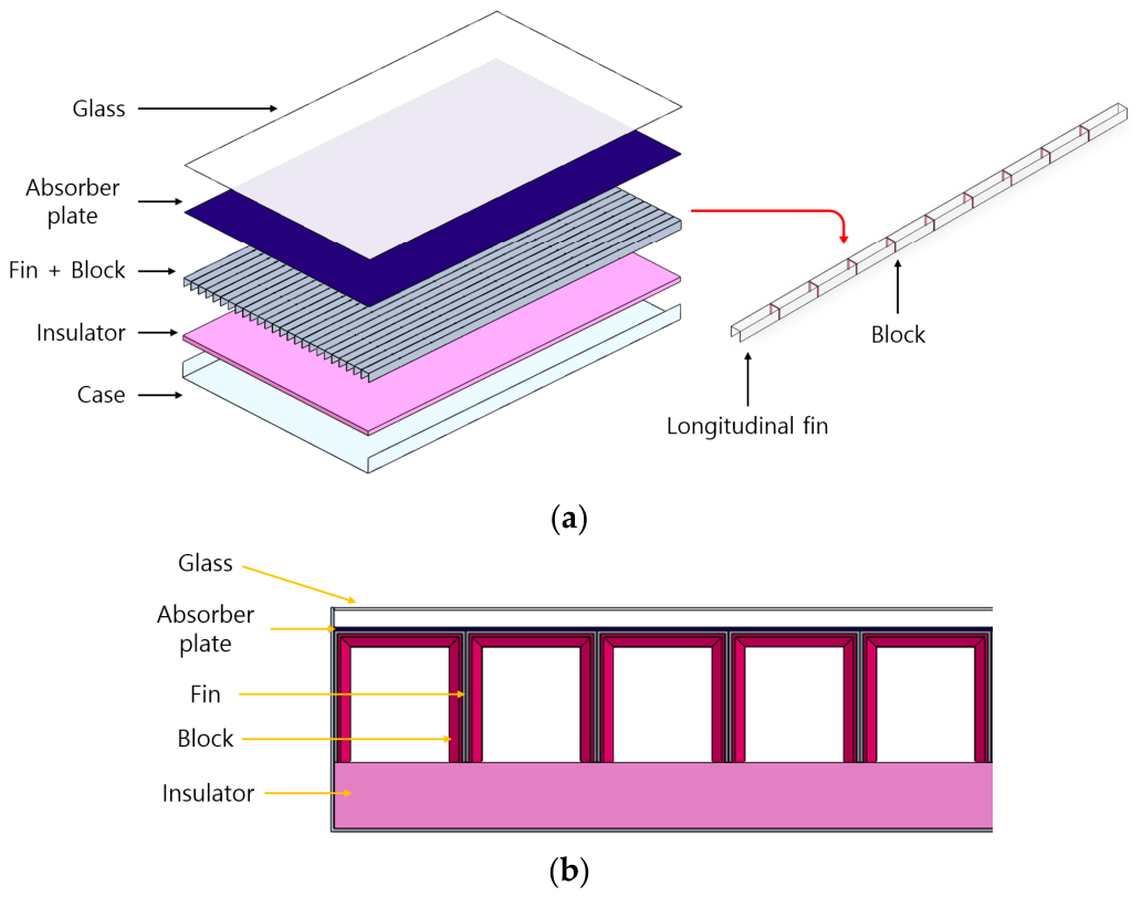
This research evaluated SAHFB via CFD analysis utilizing ANSYS Fluent 2023 R2 (ANSYS Inc., Canonsburg, PA, USA). Figure 1 illustrates a schematic of the proposed SAHFB. The absorber plate is positioned in direct contact with the upper surface of the fins. Accordingly, solar thermal energy transmitted through the glass cover is captured by the absorber plate and conducted to the top surface of the fins and subsequently along the vertical fins. The thermal energy is then dissipated from both the top and vertical fin surfaces to the airflow. Blocks are installed on the fin surfaces to improve the heat transfer coefficient, while the fins extend the heat transfer area.
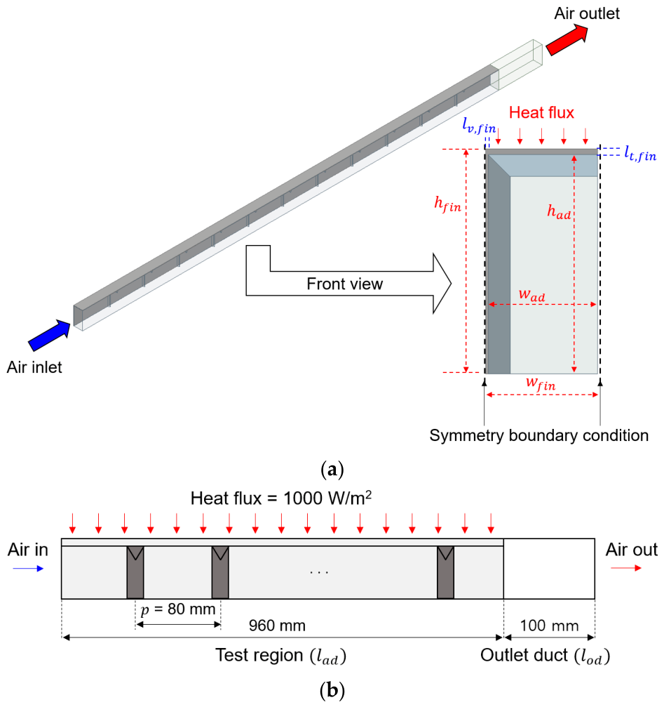
To investigate the influence of block shape within a finned air channel, a single channel formed by the fins was modeled for CFD analysis. The numerical model domain, illustrated in Figure 2, comprises a test region and an outlet duct. To decrease the numerical model domain through geometric symmetry, symmetry boundaries were imposed on the fin surface and the air-channel centerline, as shown in Figure 2a. Consequently, the height ( h a d ) and width ( w a d ) of the air duct were defined as 40 mm and 20 mm, respectively. The top fin thickness ( l t , f i n ) was 1 mm, whereas the vertical fin thickness ( l v , f i n ) was set to 0.5 mm to account for the symmetry condition. The length of the test region ( l a d ) and the outlet duct ( l o d ) were 960 mm and 100 mm, respectively. Within the test region, blocks were positioned at a constant pitch ( p ) of 80 mm. Table 1 and Table 2 summarize the detailed dimensions of the simulation model and thermophysical properties of the aluminum fin and air used in the simulation, respectively.
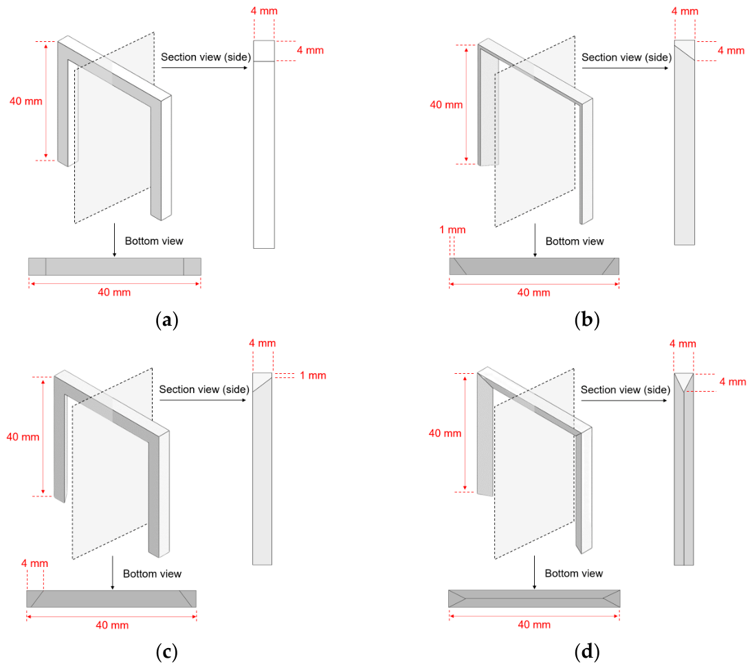
Four differently shaped blocks—rectangular block (RB), forward-chamfered rectangular block (FCRB), backward-chamfered rectangular block (BCRB), and triangular block (TB)—were investigated in this study. Figure 3 illustrates the schematics and dimensions of these blocks.

2.2. Boundary Conditions and Solution Strategy

As noted earlier, symmetry boundary conditions were employed at the vertical fin and the center of the air duct. A uniform heat flux of 1000 W/m2 was imposed on the upper boundary of the domain to simulate solar radiation, referring to relevant previous studies [4,32,33]. In an actual SAH, the heat flux transferred to the absorber or fin surface is generally lower than the incident solar irradiance owing to optical and thermal losses. Thus, it should be noted that the heat flux of 1000 W/m2 was used to compare the relative effects of block shape under identical heating conditions, rather than to directly predict actual SAH performance. An adiabatic wall condition was assigned to the remaining walls, and all solid walls were treated as no-slip. A uniform velocity was prescribed at the inlet, while the outlet was maintained at a constant pressure of 101,325 Pa. Table 3 provides the boundary conditions specified for the CFD analysis.
A numerical simulation was performed employing ANSYS Fluent 2023 R2, a commercial CFD package, assuming steady and incompressible flow. Based on the boundary conditions described above, the governing transport equations (mass, momentum, energy, and turbulence) were solved using a second-order upwind discretization scheme. Pressure–velocity coupling was achieved via the coupled algorithm. The energy equation was solved with a convergence criterion of 10−6, while the other equations were solved with a convergence criterion of 10−5.

2.3. Turbulence Model Selection

The selection of an appropriate turbulence model was conducted by validating CFD-predicted Nusselt numbers and friction factors for a smooth-fin SAH against well-known empirical correlations. Although validation of the separated flow induced by the blocks would require experimental data for the same or a similar blocked fin channel, such data are currently unavailable. Therefore, considering that this study focuses on the comparative analysis among different block shapes, smooth-fin validation was used as the basis for turbulence model selection, as commonly performed in previous CFD studies. Different turbulence models were assessed based on predicted Nusselt numbers on the fin’s top surface ( N u t ) and vertical surface ( N u v ), along with the corresponding friction factor. The Nusselt numbers were validated against the Gnielinski correlation and Dittus–Boelter equation, which are commonly employed empirical correlations for the CFD validation of SAHs [32,34,35,36]. The Gnielinski correlation and Dittus–Boelter equation are expressed as follows:
N u s = f g / 8 R e 1000 P r 1 + 12.7 f g / 8 1 / 2 P r 2 / 3 1   for   3000 < R e < 10,000
N u s = 0.023 R e 0.8 P r 0.4   for   R e > 10,000
where
f g = 0.79 ln R e 1.64 2
Furthermore, the friction factor obtained from the simulations was compared with the modified Blasius correlation, which is widely used for validation in SAHs [37,38,39]:
f s = 0.085 R e 1 / 4
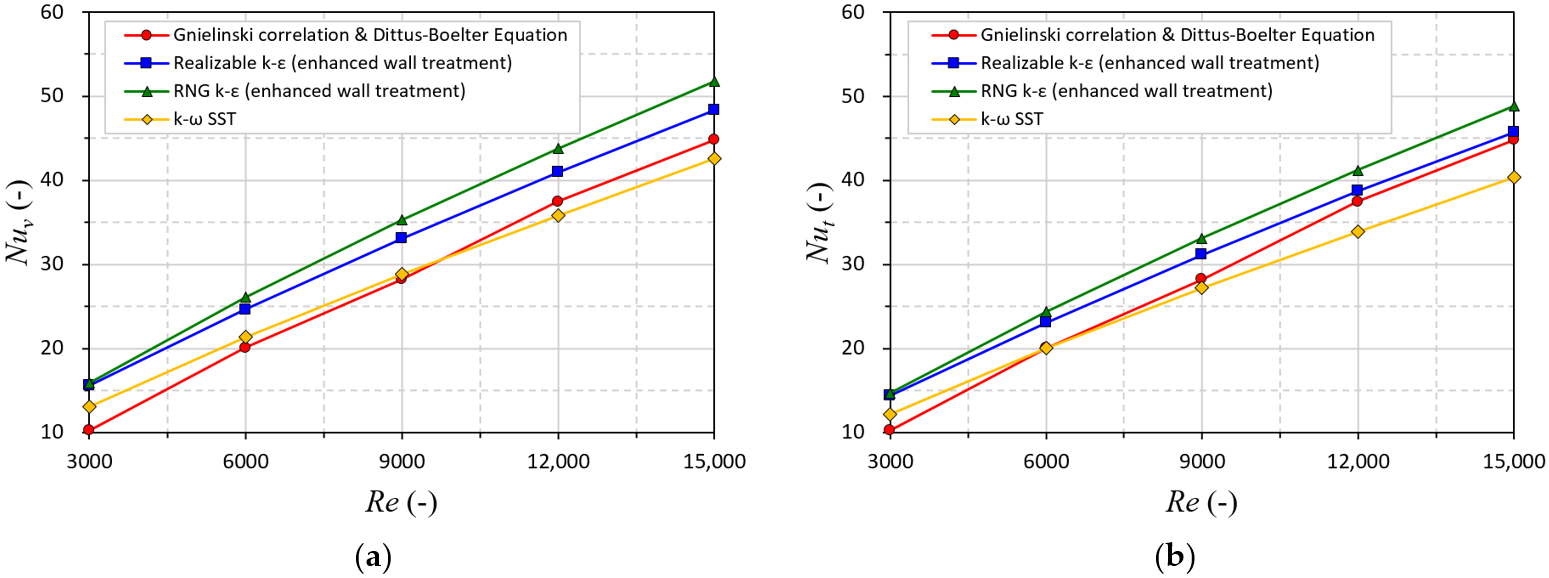
Figure 4 illustrates N u t and N u v obtained from the CFD results in relation to the Gnielinski correlation and Dittus–Boelter equation. Among the examined turbulence models, the SST k - ω model yielded the lowest mean absolute percent error (MAPE), with values of 8.36% for N u v and 9.13% for N u t . The friction factor validation also demonstrated that the SST k - ω model yielded the highest accuracy, with a MAPE of 5.48%. This result is consistent with findings from prior research [13,34,40]. Consequently, the SST k - ω model was adopted for the subsequent analysis.

2.4. Governing Equations

As steady, incompressible, and turbulent flow was assumed, the heat transfer and flow fields were governed by the continuity, momentum, and energy equations, which can be expressed as follows [13,41]:
u j x j = 0
ρ u i u j x j = p x i + x j μ u i x j + u j x i + x j μ t u i x j + u j x i
ρ u i T x i = x j μ P r + μ t P r t T x j
where μ and μ t denote the molecular and turbulent viscosity, respectively, and P r and P r t are the molecular and turbulent Prandtl numbers, respectively.
This study employed the SST k - ω model to model the turbulent flow, based on the results in Section 2.4. This model combines the advantages of the k - ω model near the wall and k - ε model in the free-stream region. The transport equations for k and ω are expressed as follows [40,41,42]:
ρ k u i x i = x j Γ k k x j + G k Y k + S k
ρ ω u j x i = x i Γ ω ω x j + G ω Y ω + S ω
where k is the turbulence kinetic energy and ω is the specific dissipation rate. G k and G ω are the production terms, Γ k and Γ ω are the effective diffusivities, and Y k and Y ω are the dissipation terms for k and ω , respectively. S k and S ω are source terms. Further details of the SST k - ω model can be found in Ref. [41].

2.5. Grid Independence

A grid independence test was performed to ensure the numerical accuracy of the results. Variations in N u t , N u v and f a v g were evaluated for the SAHFB with TB, which has a relatively complex structure compared to other shapes, by increasing the mesh density from 833,476 to 7,264,256 cells at a Reynolds number ( R e ) of 9000. A non-uniform mesh was generated, and inflation layers were applied to capture the boundary-layer gradients near the surfaces more precisely.
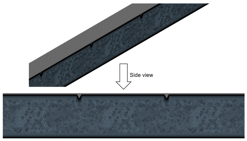
Table 4 presents the variations in N u t , N u v and f a v g with respect to the cell number. The numerical results converged, with variations below 1% for cell numbers exceeding 5,679,902. This indicates that further mesh refinement had a negligible effect on the results, confirming that the solution is grid-independent. Accordingly, the corresponding mesh density was adopted for all further analyses. The final mesh was generated using an element size of 8.8 × 10⁻⁴ m and 18 inflation layers near the wall. The first inflation layer height was set to 1.0 × 10⁻⁴ m, ensuring that the corresponding y+ value remained close to or below 1. The generated mesh had an average orthogonal quality of 0.776, indicating acceptable mesh quality. Figure 5 displays the discretized computational domain using the selected grid density.

2.6. Data Reduction

In the SAHFB, heat transfer occurs across both the top and vertical surfaces of the fin. Consequently, the Nusselt numbers for the top surface ( N u t ) and the vertical surface ( N u v ) are evaluated using Equations (10) and (11), respectively:
N u t   =   h t D h k a i r
N u v = h v D h k a i r
The hydraulic diameter, D h , was calculated based on the full air channel cross-section of 40 mm × 40 mm. The convective heat transfer coefficients for the top surface ( h t ) and the vertical surface ( h v ) were determined using the following expressions:
h t = Q ˙ t A t T t T a i r , a v g
h v = Q ˙ v A v T v T a i r , a v g
where T a i r , a v g refers to the mass-averaged temperature of the air flowing through the finned air channel. T t and T v denote average temperatures of the top and vertical surfaces of the fin, respectively.
The average Nusselt number ( N u a v g ), characterizing convective heat transfer between the fin and the airflow, was determined according to Equation (14).
N u a v g = h a v g D h k a i r
The total heat transfer rate resulting from the top and vertical fin surfaces in contact with the air stream can be written as:
Q ˙ t o t = h a v g A t + A v T f i n , a v g T a i r , a v g
Accordingly, the average convective heat transfer coefficient over the fin surface is expressed as:
h a v g =   Q ˙ t o t A t + A v T f i n , a v g T a i r , a v g
where T f i n , a v g is the average temperature of the entire fin, including both the top and vertical surfaces.
The average friction factor in the SAHFB was determined based on the pressure drop obtained from the simulation and Equation (17) [38,43,44].
f a v g = Δ P / l a d D h 2 ρ a i r V a i r 2
Since the introduction of blocks induces frictional penalties alongside heat transfer enhancement, both effects should be considered simultaneously to identify an appropriate block shape. To this end, the thermo-hydraulic performance parameter (THPP), which is commonly used as a representative index for evaluating the overall thermo-hydraulic performance of SAHs, was employed and is expressed as follows [45,46,47]:
T H P P =   N u a v g / N u s f a v g / f s 1 / 3
where the N u a v g / N u s represents the degree of heat transfer enhancement relative to the smooth fin channel, and f a v g / f s quantifies the increase in friction factor induced by the block. A higher THPP indicates superior thermal performance for a given pressure drop.

3. Results and Discussion

3.1. Thermal Performance

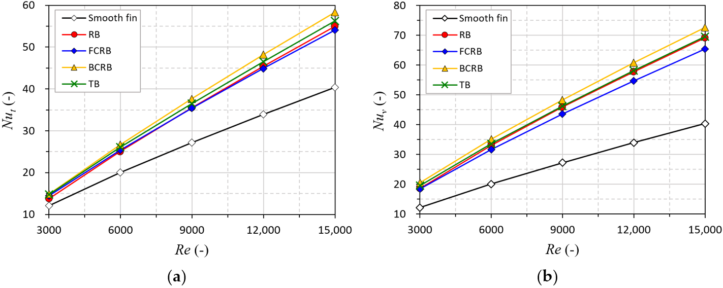
The influence of block shapes on heat transfer enhancement is examined in this subsection. Figure 6 presents the N u t and N u v for the various block shapes. It is evident that heat transfer is effectively enhanced on both the top and vertical surfaces of the fins due to the presence of the blocks. Additionally, different block shapes induce different levels of heat transfer enhancement, demonstrating the influence of block geometry on thermal performance. For both N u t and N u v , the highest heat transfer is observed for BCRB, followed by TB, RB, and FCRB.
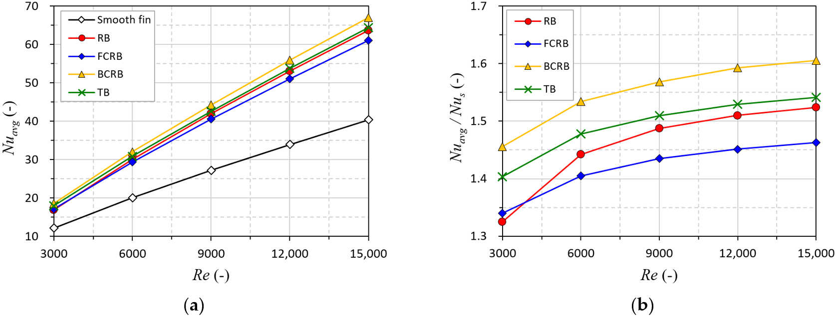
Figure 7 presents the N u a v g and its enhancement for different block shapes. The N u a v g values range from 16.9 to 63.61 for RB, 17.10 to 61.04 for FCRB, 18.57 to 67.01 for BCRB, and 17.9 to 64.34 for TB. The presence of the blocks enhances heat transfer from the finned surface to the airflow by 1.52, 1.46, 1.61, and 1.54 times for RB, FCRB, BCRB, and TB, respectively. The N u a v g values follow the order of BCRB, TB, RB, and FCRB. Moreover, BCRB exhibits the highest N u a v g regardless of the Re. This indicates that the block shape directly affects the heat transfer performance in the fin channel, because different block geometries induce different flow structures.
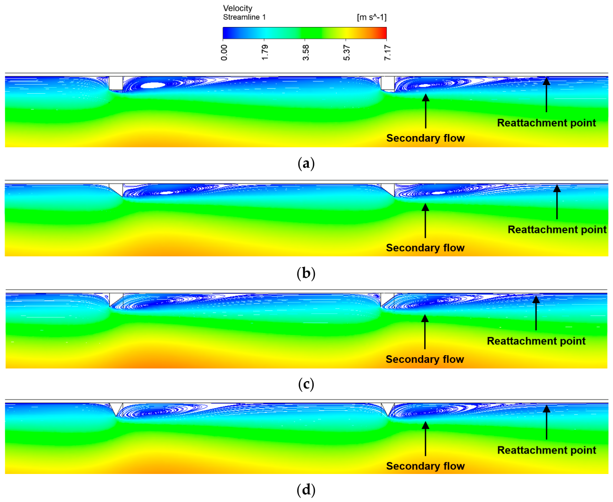
Figure 8 illustrates the streamline in the mid-plane parallel to the vertical fins at an Re of 9000 for the SAHFB with different block shapes. The flow structures vary depending on the block shapes, and secondary flow is observed primarily behind the blocks.
In the case of BCRB, which exhibited the highest N u a v g , flow separation occurs at the front of the block due to its vertical front geometry, and the sharp rear edge induces strong disturbances in the wake region. Accordingly, the most significant flow disturbance was observed among the investigated shapes. In the case of FCRB, which exhibited the lowest N u a v g , the magnitude of the secondary flow is comparatively weak because the streamlines flow smoothly over the block due to its sharp front edge, leading to delayed flow separation. Additionally, the vertical geometry at the rear of the block suppresses the development of secondary flow, resulting in weaker disturbances. Strong disturbances increase the local average Nusselt number near the block because they induce intense mixing between the hot air adjacent to the fin surface and the relatively cooler air.
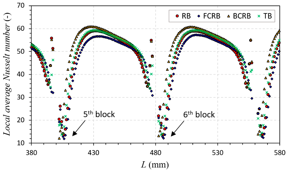
Figure 9 presents the local average Nusselt number between the 5th and 6th blocks for different block shapes. For all configurations, a sharp increase in the local average Nusselt number is observed downstream of the block due to the secondary flow, which enhances mixing between the relatively hot air and the relatively cool air. After reaching a maximum value, it decreases as the thermal boundary layer redevelops following flow reattachment. The highest local average Nusselt number is observed for the BCRB owing to strong secondary flow, whereas the lowest value is observed for the FCRB owing to weak flow disturbances. The maximum local average Nusselt number between the 5th and 6th blocks was observed as 58.99, 56.66, 60.84, and 59.22 for the RB, FCRB, BCRB, and TB, respectively, while the corresponding average values were 48.46, 46.47, 51.46, and 49.31. Consequently, the BCRB, which provides strong secondary flow, is considered the most beneficial for heat transfer among the investigated block shapes.

3.2. Friction Factor

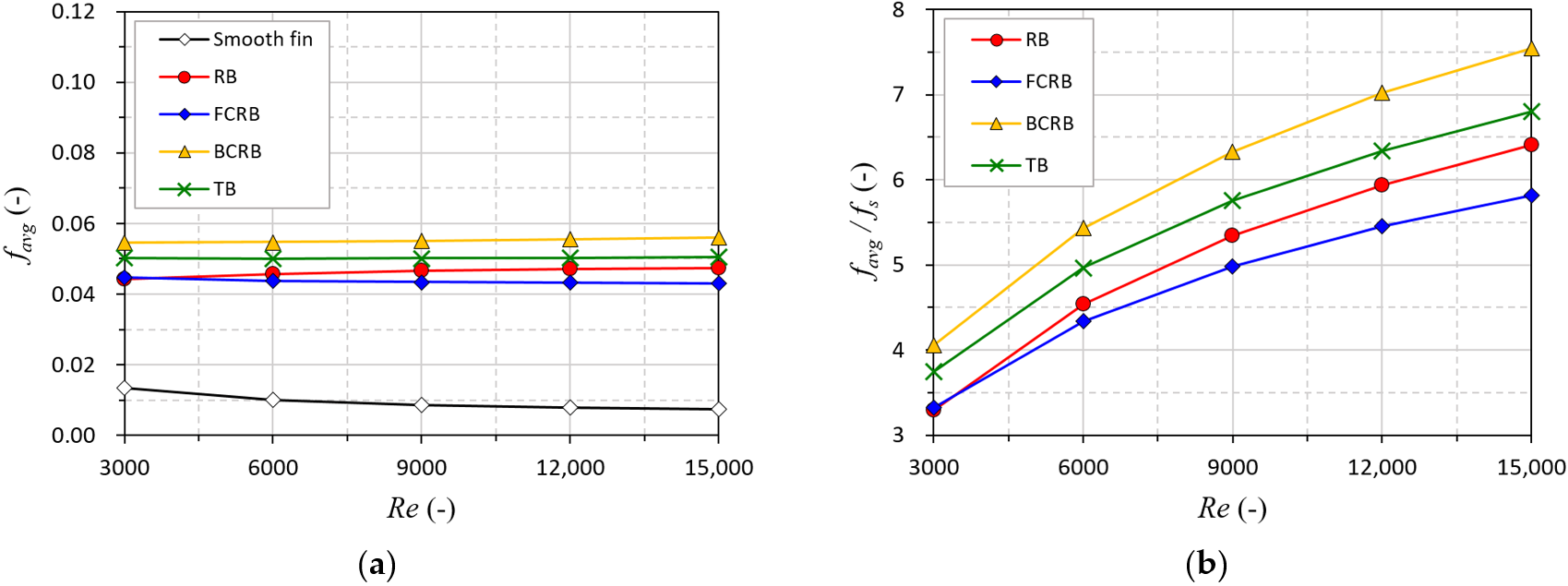
The installation of blocks introduces frictional penalties due to the increased flow resistance from stronger secondary flow, while enhancing heat transfer performance. The predicted f a v g for different block shapes is presented in Figure 10. The values of f a v g vary from 0.0442 to 0.0475 for the RB, from 0.0431 to 0.0448 for the FCRB, from 0.0546 to 0.0559 for the BCRB, and from 0.05 to 0.0504 for the TB.
The introduction of blocks into the fin channel leads to a substantial rise in f a v g with increase factors of 6.41, 5.82, 7.55, and 6.80 for RB, FCRB, BCRB, and TB, respectively. Different block shapes provide different f a v g values because they form distinct secondary flow structures. The highest f a v g is observed for the BCRB regardless of Re. This is because the intense secondary flow, which flows in the opposite direction of the main flow, leads to a significant increase in pressure drop. Meanwhile, the lowest f a v g is obtained for the FCRB due to the relatively weak secondary flow.

3.3. Thermo-Hydraulic Performance Parameter

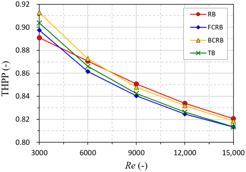
As shown above, stronger secondary flow results in a larger frictional penalty as well as greater heat transfer improvement. Therefore, heat transfer enhancement should be evaluated in conjunction with the associated frictional penalty. Figure 11 presents the THPP values for different block shapes.
The THPP ranges from 0.821 to 0.891 for the RB, from 0.813 to 0.898 for the FCRB, from 0.819 to 0.913 for the BCRB, and from 0.814 to 0.904 for the TB. The maximum THPP is observed for the BCRB when Re is below 6000, owing to its significant heat transfer enhancement despite its highest frictional penalty. The RB exhibits the highest THPP at Re of 9000 or above, which is attributed to its lower frictional penalty compared to the BCRB. In the case of the TB, higher heat transfer enhancement is achieved compared to the RB; however, a lower THPP is observed than that of the RB due to the high f a v g . Therefore, the BCRB is considered a relatively suitable block shape among the investigated shapes for the fin channel of the SAHFB at Re below 6000, whereas the RB is more suitable at Re above 9000. However, all THPP values were lower than unity, indicating that the pressure drop penalty outweighed the heat transfer enhancement. Thus, these shapes should be regarded as relatively promising baseline shapes rather than final optimal designs. Further optimization of geometric parameters, such as block height, pitch, thickness, and arrangement, is required to reduce the frictional penalty while maintaining heat transfer enhancement.

4. Conclusions

This study investigated the effects of different block shapes installed in the fin channel of an SAHFB on the heat transfer enhancement and the frictional penalty. Additionally, the overall performance, considering both heat transfer and the frictional penalty, was evaluated through the THPP. The key findings reported in this work are as follows:
(i)
The addition of the blocks in the fin channel effectively enhanced the heat transfer performance in the SAHFB. Within the investigated configurations, the highest heat transfer enhancement of 1.61 times was observed for the BCRB, while the TB, RB, and FCRB yielded maximum values of 1.54, 1.52, and 1.46 times, respectively.
(ii)
The installation of blocks is accompanied by a frictional penalty. The maximum increase in f a v g was observed to be 7.55 times for the BCRB, followed by increases of 6.80, 6.41, and 5.82 times for the TB, RB, and FCRB, respectively.
(iii)
The THPP varied from 0.821 to 0.891, 0.813 to 0.898, 0.819 to 0.913, and 0.814 to 0.904 for the RB, FCRB, BCRB, and TB, respectively. The highest THPP was achieved for the BCRB at Re below 6000, whereas the RB exhibited the highest THPP at Re above 9000.
(iv)
Among the considered block shapes, the BCRB exhibited the highest THPP at Re below 6000, whereas the RB showed the highest THPP at Re above 9000. However, because all THPP values were lower than unity, these shapes are regarded as promising baseline shapes rather than final optimal designs.
The current study confirms that different block shapes apparently influence the heat transfer performance, flow structure, and the friction characteristics of the SAHFB. Specifically, the BCRB and RB exhibit relatively favorable THPP compared with the other tested shapes, depending on the Reynolds number range. Therefore, the findings of this study are expected to provide a useful basis for selecting baseline block geometries and for supporting subsequent geometric optimization of SAHs with finned air channels. However, this research was limited to analyzing heat transfer and frictional penalties associated with various block shapes based on CFD analysis. Future research will focus on optimizing the geometric parameters of the blocks and evaluating the comprehensive performance of the SAHFB, including outlet air temperature rise, thermal efficiency, pumping power, and experimental feasibility.

Author Contributions

Conceptualization, B.-H.A. and H.-U.C.; methodology, B.-H.A., K.-A.M. and E.Y.; software, B.-H.A.; validation, B.-H.A. and E.Y.; investigation, K.-A.M. and H.-U.C.; data curation, B.-H.A. and E.Y.; writing—original draft preparation, B.-H.A. and E.Y.; writing—review and editing, B.-H.A. and H.-U.C.; visualization, B.-H.A. and H.-U.C. All authors have read and agreed to the published version of the manuscript.

Funding

This research received no external funding.

Data Availability Statement

Data available on request.

Conflicts of Interest

The authors declare no conflicts of interest.

Abbreviations

SAHSolar air heater
SAHFBSolar air heater with fins and blocks
RBRectangular block
FCRBForward-chamfered rectangular block
BCRBBackward-chamfered rectangular block
TBTriangular block
THPPThermo-hydraulic performance parameter (-)
Nomenclature
AArea
D h Hydraulic diameter (m)
h Convective heat transfer coefficient (W/m2·K)
k a i r Thermal conductivity (W/m·K)
l a d Length of air duct (m)
Δ P Pressure drop (Pa)
Q ˙ Heat transfer rate (W)
T Temperature (K)
V Velocity (m/s)
f Friction factor (-)
N u Nusselt number (-)
P r Prandtl number (-)
R e Reynolds number (-)
Greek letters
ρ Density (kg/m3)
Subscripts
a i r Air
a v g Average
f i n Fin
s Smooth fin
t Top surface of fin
t o t Total
v Vertical surface of fin

References

  1. Mahanand, Y.; Senapati, J.R. Implementation of hybrid rib-turbulators on the thermal performance of solar air heater duct: A collective review. Sustain. Energy Technol. Assess. 2022, 52, 102345. [Google Scholar] [CrossRef] [Scilit]
  2. Gawande, V.B.; Dhoble, A.S.; Zodpe, D.B.; Chamoli, S. Experimental and CFD investigation of convection heat transfer in solar air heater with reverse L-shaped ribs. Sol. Energy 2016, 131, 275–295. [Google Scholar] [CrossRef] [Scilit]
  3. Thakur, S.; Thakur, N.S. Impact of multi-staggered rib parameters of the ‘W’ shaped roughness on the performance of a solar air heater channel. Energy Sources Part A Recovery Util. Environ. Eff. 2020, 46, 8378–8397. [Google Scholar] [CrossRef] [Scilit]
  4. Boussouar, G.; Rostane, B.; Aliane, K.; Ravi, D.; Gęca, M.J.; Gola, A. Study of the Thermal Performance of Solar Air Collectors with and without Perforated Baffles. Energies 2024, 17, 3812. [Google Scholar] [CrossRef] [Scilit]
  5. Hu, J.; Zhang, Y.; Xie, S.; Xiao, Y. Thermo-hydraulic performance of solar air heater with built-in one-eighth sphere vortex generators. Appl. Therm. Eng. 2024, 245, 122837. [Google Scholar] [CrossRef] [Scilit]
  6. Winsly, B.W.; Benjamin, P.A.; Chockalingam, M.P.; Santhappan, J.S.; Prabakaran, R.; Kim, S.C. Effect of Subducting Baffle Structure in Solar Air Heaters: A CFD Insight into Thermo-Hydraulic Performance. Energies 2025, 18, 6223. [Google Scholar] [CrossRef] [Scilit]
  7. Yadav, A.S.; Bhagoria, J.L. A CFD (computational fluid dynamics) based heat transfer and fluid flow analysis of a solar air heater provided with circular transverse wire rib roughness on the absorber plate. Energy 2013, 55, 1127–1142. [Google Scholar] [CrossRef] [Scilit]
  8. Yadav, A.S.; Bhagoria, J.L. A numerical investigation of square sectioned transverse rib roughened solar air heater. Int. J. Therm. Sci. 2014, 79, 111–131. [Google Scholar] [CrossRef] [Scilit]
  9. Yadav, A.S.; Bhagoria, J.L. A CFD based thermo-hydraulic performance analysis of an artificially roughened solar air heater having equilateral triangular sectioned rib roughness on the absorber plate. Int. J. Heat Mass Transf. 2014, 70, 1016–1039. [Google Scholar] [CrossRef] [Scilit]
  10. Singh, I.; Singh, S. CFD analysis of solar air heater duct having square wave profiled transverse ribs as roughness elements. Sol. Energy 2018, 162, 442–453. [Google Scholar] [CrossRef] [Scilit]
  11. Kumar, B.V.; Kanna, P.R.; Manikandan, G.; Taler, D.; Taler, J.; Sobota, T.; Nowak-Ocłoń, M. Investigation of Thermo-Hydraulic Performances of Artificial Ribs Mounted in a Rectangular Duct. Energies 2023, 16, 4404. [Google Scholar] [CrossRef] [Scilit]
  12. Thao, P.B.; Truyen, D.C.; Phu, N.M. CFD Analysis and Taguchi-Based Optimization of the Thermohydraulic Performance of a Solar Air Heater Duct Baffled on a Back Plate. Appl. Sci. 2021, 11, 4645. [Google Scholar] [CrossRef] [Scilit]
  13. Alam, M.W.; Souayeh, B. Parametric CFD Thermal Performance Analysis of Full, Medium, Half and Short Length Dimple Solar Air Tube. Sustainability 2021, 13, 6462. [Google Scholar] [CrossRef] [Scilit]
  14. Singh, S.; Suman, S.; Mitra, S.; Kumar, M. Thermo-hydraulic performance enhancement of a solar air heater using rotating cylindrical turbulators. Appl. Therm. Eng. 2024, 236, 121748. [Google Scholar] [CrossRef] [Scilit]
  15. Fudholi, A.; Sopian, K.; Ruslan, M.H.; Othman, M.Y. Performance and cost benefits analysis of double-pass solar collector with and without fins. Energy Convers. Manag. 2013, 76, 8–19. [Google Scholar] [CrossRef] [Scilit]
  16. Kabeel, A.E.; Hamed, M.H.; Omara, Z.M.; Kandeal, A.W. Influence of fin height on the performance of a glazed and bladed entrance single-pass solar air heater. Sol. Energy 2018, 162, 410–419. [Google Scholar] [CrossRef] [Scilit]
  17. Saravanan, A.; Parida, S.; Murugan, M.; Reddy, M.S.; Elumalai, P.V.; Kumar Dash, S. Thermal performance prediction of a solar air heater with a C-shape finned absorber plate using RF, LR and KNN models of Machine learning. Therm. Sci. Eng. Prog. 2023, 38, 101630. [Google Scholar] [CrossRef] [Scilit]
  18. Karwa, R. Thermo-hydraulic performance of solar air heater with finned absorber plate forming multiple rectangular air flow passages in parallel under laminar flow conditions. Appl. Therm. Eng. 2023, 221, 119673. [Google Scholar] [CrossRef] [Scilit]
  19. Elakrout, O.; Ghriss, O.; Bouabidi, A.; Garcia Castellanos, H.; Mohtaram, S.; Keçebaş, A.; Aryanfar, Y. Investigative analysis of the influence of diverse fin configurations on the performance of a dual pass solar air collector. Therm. Sci. Eng. Prog. 2024, 50, 102545. [Google Scholar] [CrossRef] [Scilit]
  20. Yang, M.; Yang, X.; Li, X.; Wang, Z.; Wang, P. Design and optimization of a solar air heater with offset strip fin absorber plate. Appl. Energy 2014, 113, 1349–1362. [Google Scholar] [CrossRef] [Scilit]
  21. Priyam, A.; Chand, P. Thermal and thermohydraulic performance of wavy finned absorber solar air heater. Sol. Energy 2016, 130, 250–259. [Google Scholar] [CrossRef] [Scilit]
  22. Priyam, A.; Chand, P. Effect of wavelength and amplitude on the performance of wavy finned absorber solar air heater. Renew. Energy 2018, 119, 690–702. [Google Scholar] [CrossRef] [Scilit]
  23. Bhattacharyya, T.; Anandalakshmi, R.; Srinivasan, K. Heat Transfer Analysis on Finned Plate Air Heating Solar Collector for its Application in Paddy Drying. Energy Procedia 2017, 109, 353–360. [Google Scholar] [CrossRef] [Scilit]
  24. Chand, S.; Chand, P.; Kumar Ghritlahre, H. Thermal performance enhancement of solar air heater using louvered fins collector. Sol. Energy 2022, 239, 10–24. [Google Scholar] [CrossRef] [Scilit]
  25. Nagaraj, M.; Reddy, M.K.; Sheshadri, A.K.H.; Karanth, K.V. Numerical Analysis of an Aerofoil Fin Integrated Double Pass Solar Air Heater for Thermal Performance Enhancement. Sustainability 2023, 15, 591. [Google Scholar] [CrossRef] [Scilit]
  26. Albdoor, A.K.; Obaid, Z.A.H.; Kamel, M.S.; Azzawi, I.D.J. Energy, exergy, economic and environmental analysis of a solar air heater integrated with double triangular fins: Experimental investigation. Int. J. Thermofluids 2024, 24, 100979. [Google Scholar] [CrossRef] [Scilit]
  27. Elakrout, O.; Ghriss, O.; Bouabidi, A.; Vanierschot, M. Experimental and Numerical Investigation of a Novel Low-Cost Solar Air Heater with Large-Scale V-Shaped Fins to Enhance Heat Transfer. Energies 2025, 18, 5503. [Google Scholar] [CrossRef] [Scilit]
  28. Nidhul, K.; Yadav, A.K.; Anish, S.; Kumar, S. Critical review of ribbed solar air heater and performance evaluation of various V-rib configuration. Renew. Sustain. Energy Rev. 2021, 142, 110871. [Google Scholar] [CrossRef] [Scilit]
  29. Ghritlahre, H.K.; Verma, M.; Parihar, J.S.; Mondloe, D.S.; Agrawal, S. A detailed review of various types of solar air heaters performance. Sol. Energy 2022, 237, 173–195. [Google Scholar] [CrossRef] [Scilit]
  30. Markam, B.; Maiti, S. Artificial enhancer for small-scale solar air heater—A comprehensive review. Clean Energy Syst. 2023, 4, 100046. [Google Scholar] [CrossRef] [Scilit]
  31. Choi, H.-U.; Moon, K.-A.; Kim, S.-B.; Choi, K.-H. CFD Analysis of the Heat Transfer and Fluid Flow Characteristics Using the Rectangular Rib Attached to the Fin Surface in a Solar Air Heater. Sustainability 2023, 15, 5382. [Google Scholar] [CrossRef] [Scilit]
  32. Kumar, R.; Goel, V. Unconventional solar air heater with triangular flow-passage: A CFD based comparative performance assessment of different cross-sectional rib-roughnesses. Renew. Energy 2021, 172, 1267–1278. [Google Scholar] [CrossRef] [Scilit]
  33. Haldar, A.; Varshney, L.; Verma, P. Effect of roughness parameters on performance of solar air heater having artificial wavy roughness using CFD. Renew. Energy 2022, 184, 266–279. [Google Scholar] [CrossRef] [Scilit]
  34. Kumar, S.; Verma, S.K. Heat transfer and fluid flow analysis of sinusoidal protrusion rib in solar air heater. Int. J. Therm. Sci. 2022, 172, 107323. [Google Scholar] [CrossRef] [Scilit]
  35. An, B.H.; Moon, K.A.; Kim, S.B.; Choi, H.U. Analysis of Heat Transfer and Fluid Flow in a Solar Air Heater with Sequentially Placed Rectangular Obstacles on the Fin Surface. Energies 2025, 18, 3811. [Google Scholar] [CrossRef] [Scilit]
  36. Singh, A.; Singh, S. CFD investigation on roughness pitch variation in non-uniform cross-section transverse rib roughness on Nusselt number and friction factor characteristics of solar air heater duct. Energy 2017, 128, 109–127. [Google Scholar] [CrossRef] [Scilit]
  37. Nidhul, K.; Yadav, A.K.; Anish, S.; Arunachala, U.C. Efficient design of an artificially roughened solar air heater with semi-cylindrical side walls: CFD and exergy analysis. Sol. Energy 2020, 207, 289–304. [Google Scholar] [CrossRef] [Scilit]
  38. Patel, S.S.; Lanjewar, A. Experimental investigation of solar air heater duct with discrete V-rib integrated with staggered elements. Int. J. Sustain. Eng. 2021, 14, 162–171. [Google Scholar] [CrossRef] [Scilit]
  39. Choi, H.-U. Dynamic analysis of air-based photovoltaic–thermal system with fins and rectangular obstacles. Appl. Therm. Eng. 2025, 272, 126412. [Google Scholar] [CrossRef] [Scilit]
  40. Alam, T.; Kim, M.-H. Heat transfer enhancement in solar air heater duct with conical protrusion roughness ribs. Appl. Therm. Eng. 2017, 126, 458–469. [Google Scholar] [CrossRef] [Scilit]
  41. ANSYS. ANSYS Fluent 12.0 User’s Guide; ANSYS Inc.: Canonsburg, PA, USA, 2009. [Google Scholar]
  42. Wongcharee, K.; Changcharoen, W.; Eiamsa-ard, S. Numerical Investigation of Flow Friction and Heat Transfer in a Channel with Various Shaped Ribs Mounted on Two Opposite Ribbed Walls. Int. J. Chem. React. Eng. 2011, 9, A26. [Google Scholar] [CrossRef]
  43. Kumar, A.; Saini, R.P.; Saini, J.S. Experimental investigation on heat transfer and fluid flow characteristics of air flow in a rectangular duct with Multi v-shaped rib with gap roughness on the heated plate. Sol. Energy 2012, 86, 1733–1749. [Google Scholar] [CrossRef] [Scilit]
  44. Kim, S.-B.; Choi, H.-U. Numerical analysis of photovoltaic–thermal air collector with fins and rectangular turbulators. Therm. Sci. Eng. Prog. 2025, 59, 103393. [Google Scholar] [CrossRef] [Scilit]
  45. Webb, R.L.; Eckert, E.R.G. Application of rough surfaces to heat exchanger design. Int. J. Heat Mass Transf. 1972, 15, 1647–1658. [Google Scholar] [CrossRef] [Scilit]
  46. Gupta, A.D.; Varshney, L. Performance prediction for solar air heater having rectangular sectioned tapered rib roughness using CFD. Therm. Sci. Eng. Prog. 2017, 4, 122–132. [Google Scholar] [CrossRef] [Scilit]
  47. Kumar, R.; Kumar, A.; Goel, V. Performance improvement and development of correlation for friction factor and heat transfer using computational fluid dynamics for ribbed triangular duct solar air heater. Renew. Energy 2019, 131, 788–799. [Google Scholar] [CrossRef] [Scilit]
Figure 1. Schematic of SAHFB: (a) isometric; (b) front view.
Processes 14 02001 g001
Figure 2. Numerical model domain (a) 3D domain; (b) side view.
Processes 14 02001 g002
Figure 3. Schematics and dimensions of the blocks: (a) RB; (b) FCRB; (c) BCRB; (d) TB.
Processes 14 02001 g003
Figure 4. Comparison of turbulence-model-based Nusselt numbers and empirical correlations: (a) top surface; (b) vertical surface.
Processes 14 02001 g004
Figure 5. Computational domain using the selected grid density.
Processes 14 02001 g005
Figure 6. Impact of block shapes on the Nusselt number: (a) top surface; (b) vertical surface.
Processes 14 02001 g006
Figure 7. Impact of block shapes on the Nusselt number: (a) average value; (b) Nusselt number enhancement.
Processes 14 02001 g007
Figure 8. Streamline variation in the mid-plane parallel to the vertical fin at an Re of 9000: (a) RB; (b) FCRB; (c) BCRB; (d) TB.
Processes 14 02001 g008
Figure 9. Local average Nusselt number for different block shapes at an R e of 9000.
Processes 14 02001 g009
Figure 10. Impact of block shapes on the friction factor: (a) average value; (b) increase in friction factor.
Processes 14 02001 g010
Figure 11. Impact of different block shapes on THPP.
Processes 14 02001 g011
Table 1. Dimensions of the simulation model.
ParameterValue
Air duct height (mm), h a d 40
Air duct width (mm), w a d 20
Thickness of the top side fin (mm), l t , f i n 1
Thickness of the vertical side fin (mm), l v , f i n 0.5
Length of test region (mm), l a d 960
Length of outlet duct (mm), l o d 100
Fin height (mm), h f i n 41
Fin width (mm), w f i n 20.5
Pitch of blocks (mm), p 80
Table 2. Thermophysical properties of the aluminum fin and air.
ParameterAluminum FinAir
Density (kg/m3)27191.225
Specific heat (J/kg·K) 8711006.43
Thermal conductivity (W/m·K)202.40.0242
Viscosity (kg/m·s)-1.7894 × 10−5
Table 3. Boundary conditions adopted for the current simulation.
BoundaryConditionsValues
Vertical finSymmetry-
Center of the air ductSymmetry-
Top of the finHeat flux (W/m2)1000
InletVelocity (m/s)1.096, 2.191, 3.287, 4.382, 5.478
Reynolds number (-)3000, 6000, 9000, 12,000, 15,000
OutletConstant pressure (Pa)101,325
Other wallsAdiabatic-
Solid surfacesNo-slip-
Table 4. Variations in N u t , N u v and f a v g .
Cell Number N u t
(−)
Change in N u t
(%)
N u v
(−)
Change in N u v
(%)
f a v g
(−)
Change in f a v g
(%)
833,47636.87-46.04-0.0562-
1,685,35736.560.8446.060.040.05541.47
2,621,56836.280.7745.760.640.05245.31
4,060,92336.721.2146.471.550.05392.84
5,679,90236.530.5146.240.490.05223.18
7,264,25636.670.3946.470.490.05240.33
Disclaimer/Publisher’s Note: The statements, opinions and data contained in all publications are solely those of the individual author(s) and contributor(s) and not of MDPI and/or the editor(s). MDPI and/or the editor(s) disclaim responsibility for any injury to people or property resulting from any ideas, methods, instructions or products referred to in the content.