Article

Prediction of Annular Pressure Under Wellhead Uplift Load in Deepwater Subsea Wells

1
College of Safety and Ocean Engineering, China University of Petroleum (Beijing), Beijing 102249, China
2
China United Coalbed Methane Corp., Ltd., Beijing 100011, China
3
SINOPEC Research Institute of Petroleum Engineering Co., Ltd., Beijing 102206, China
*
Author to whom correspondence should be addressed.
Processes 2026, 14(11), 1714; https://doi.org/10.3390/pr14111714
Submission received: 11 April 2026 / Revised: 6 May 2026 / Accepted: 13 May 2026 / Published: 25 May 2026

Abstract

To address the large deviation in annular trapped pressure prediction during testing and production stages of deepwater high-temperature and high-pressure wells, conventional models neglect the elastic uplift effect of the wellhead. This study overcomes the limitations of the plane strain model and establishes a three-dimensional thermos–hydro–mechanical coupled annular pressure prediction model based on the longitudinal stiffness constraint of the subsea wellhead. The deepwater wellbore–formation system is treated as a composite elastic structure. A generalized plane strain assumption is introduced to define the elastic boundary conditions and longitudinal segmentation characteristics of the wellhead. Based on generalized Hooke’s law, the three-dimensional stress–strain constitutive equation of casing is modified. A displacement model incorporating axial–radial coupling is derived, and an equivalent longitudinal stiffness coefficient of the wellhead is introduced. A coupled axial force equilibrium equation and a three-dimensional annular volume compatibility equation are established. Considering multi-annulus coupling, a volume compatibility matrix equation is formulated, and a successive approximation iterative algorithm with a relaxation factor is developed. Using a deepwater high-temperature, high-pressure gas well in the South China Sea as a case study, the effects of wellhead stiffness, free section length, and annular temperature rise on annular pressure are investigated via a single-variable method and compared with traditional rigid models. Results show that the subsea wellhead exhibits elastic uplift behavior. Its longitudinal stiffness has a reverse S-shaped nonlinear influence on annular pressure. Increasing the free section length significantly reduces annular pressure. The proposed model predicts values 17–21% lower than traditional rigid models, providing a more realistic representation of annular pressure evolution. The findings offer theoretical support and engineering guidance for deepwater well integrity design and annular pressure risk management.

1. Introduction

Deepwater oil and gas resource development faces complex geological environments and severe engineering challenges. In recent years, unconventional and complex reservoir engineering has further expanded toward fractured oil reservoirs, natural hydrogen reservoirs, and hot dry rock systems. Related studies have shown that microscopic fracture characteristics can significantly affect the flow resistance of oil displacement fluids in reservoir fractures [1], hard-core imperfections can influence fracture propagation behavior during carbon dioxide fracturing of natural hydrogen reservoirs [2], and the coupling of impact load and confining pressure release can improve the penetration rate of hot dry rock [3]. These studies indicate that reservoir engineering is increasingly characterized by complex fracture structures, multi-field coupling, and high-temperature/high-pressure conditions, which place higher requirements on the safety and integrity of deepwater wellbore systems. Shallow formations in deepwater areas usually exhibit poor diagenesis and low fracture pressure gradients. Drilling and completion operations require multi-layer casing structures to isolate complex formations, thereby forming a multi-level sealed annular system composed of inner casing, outer casing, and cement sheath interfaces [4,5,6,7]. During oil and gas testing and production stages, high-temperature formation fluids rise along the production string and transfer heat to the annular medium, causing thermal expansion of the fluid in the sealed annulus. Due to the limitation of annular volume by rigid tubulars and cement sheaths, and the lack of conventional pressure release channels in subsea wellhead devices, the thermal expansion effect is easily converted into high annular trapped pressure, which seriously threatens wellbore integrity and production safety [8,9,10,11].
Existing annular pressure prediction models are mostly based on the plane strain assumption of elasticity, i.e., assuming that the wellbore is infinitely long in the axial direction or both ends are completely rigidly fixed, and the axial strain remains unchanged [8,9,12]. This assumption is applicable to onshore wells or conductor-supported platform wells, where the wellhead device is rigidly fixed to the platform deck and axial displacement is strictly constrained. However, deepwater subsea wellheads and Christmas trees are installed on seabed guide bases and fixed through locking mechanisms and casing hanger systems. Recent theoretical studies and field monitoring data show that the subsea wellhead system is not an absolute rigid body. Under the combined action of the “end piston force” generated by thermal expansion of annular fluids and the thermal elongation force of casing, it exhibits elastic characteristics and undergoes slight axial rigid-body displacement, namely the wellhead uplift phenomenon [13,14].
Although this axial displacement is small, it significantly increases the annular length for volume-sensitive sealed liquid annuli, producing a notable volume relief effect and thus alleviating the increase in annular pressure. If this effect is neglected and the traditional rigid plane strain model is used, annular pressure will be easily overestimated, leading to overly conservative casing strength design and increased well construction costs [15,16]. At present, numerous studies have carried out thermo-solid coupling research on casing-cement-formation systems. European and American scholars have proposed a series of three-dimensional elastic models and wellhead compliance prediction frameworks, which can realize basic mechanical response analysis of wellbore deformation. However, most existing models still have two key defects: first, the wellhead boundary is simply set as rigid or free expansion, lacking quantitative characterization of wellhead longitudinal constraint stiffness; second, the coupling feedback mechanism between axial uplift displacement and annular volume change is ignored, resulting in insufficient prediction accuracy for deepwater working conditions. Compared with state-of-the-art models, the incremental innovations of this study are clarified as follows: (1) An equivalent longitudinal stiffness parameter is introduced to quantitatively describe the elastic constraint of wellhead locking structure, conductor and seabed foundation, realizing the transition from qualitative boundary assumption to quantitative mechanical characterization; (2) A novel axial–radial coupling displacement correction term is derived to establish the bidirectional feedback mechanism between annular pressure accumulation and wellhead elastic uplift; (3) A relaxation iterative matrix algorithm is constructed for multi-annulus nonlinear coupling solution, which effectively improves the numerical stability and calculation accuracy under variable working conditions.
Therefore, this paper breaks through the limitations of traditional two-dimensional models, introduces the key parameter of “longitudinal stiffness of the wellhead system”, and constructs a three-dimensional thermo–solid–fluid coupled prediction model incorporating thermal expansion, Poisson effect, and wellhead elastic uplift mechanism, to quantitatively investigate the influence of axial boundary conditions on annular pressure and provide a new method for accurate prediction of annular pressure in deepwater wells.

2. Physical Model and Basic Assumptions

2.1. Physical Model

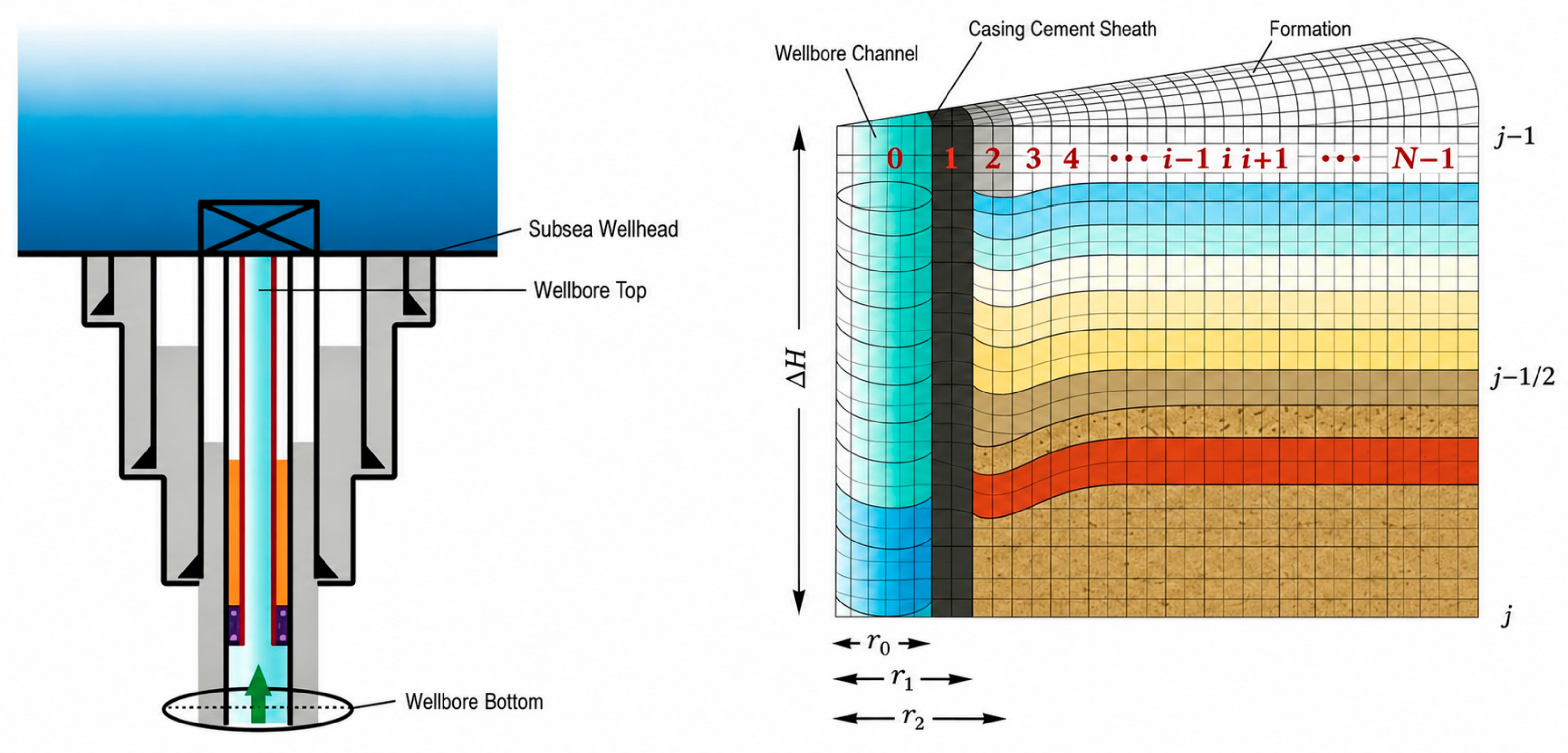
The deepwater wellbore formation system is abstracted as a composite elastic structure composed of multi-layer concentric cylindrical shells, annular fluid, cement sheath, and formation rock. Considering the special axial constraint conditions of deepwater wells, a multi-annulus physical model based on wellhead longitudinal stiffness constraint is constructed, as shown in Figure 1. The key geometric and mechanical characteristics of the model are as follows:
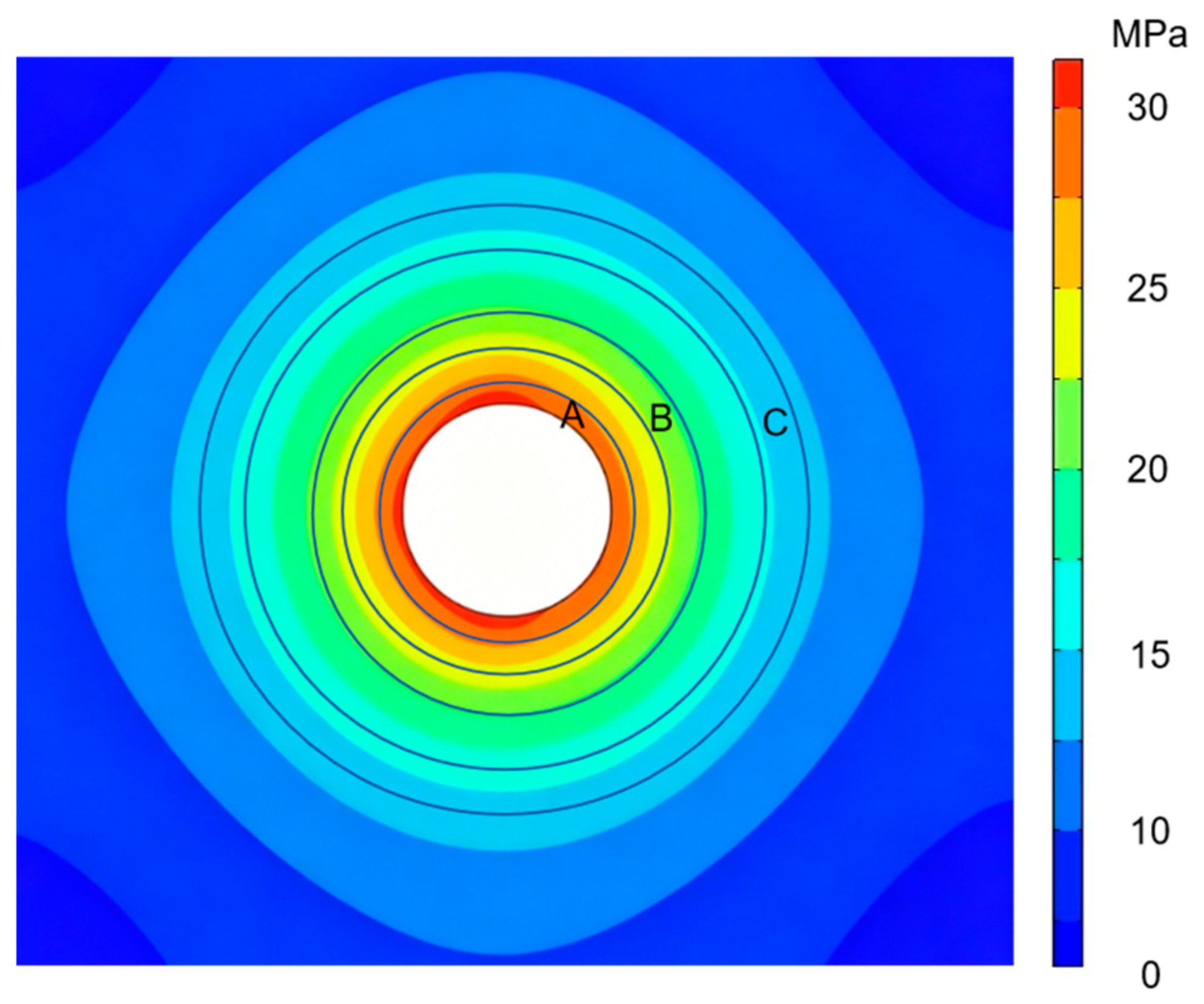
To further verify the rationality of the proposed physical model, a three-dimensional thermo-mechanical coupling numerical model is established based on COMSOL Multiphysics 6.2 software. The casing, cement sheath and formation are divided by structured grid, and refined grid division is adopted near the casing wall and wellhead constraint boundary to ensure calculation accuracy. The seabed boundary is set as elastic foundation constraint, and the wellhead top is loaded with equivalent axial stiffness constraint. The numerical model fully restores the geometric structure, material attributes and boundary conditions of the actual deepwater wellbore system, which can provide numerical verification for the theoretical derivation results.
(1) Radial structure: From inside to outside, the system consists of production tubing, multiple casing strings, cement sheath, and infinite formation. The sealed spaces formed between casing layers are annuli A, B, C, etc., filled with fluid and responsible for heat transfer and pressure bearing.
(2) Axial segmentation: According to cement return height, the wellbore is divided into a free section and a cemented section along the axial direction. In the cemented section, the casing is surrounded by cement sheath and bonded to the formation, and its axial displacement is assumed to be zero. In the free section, the casing is surrounded by liquid fluid without lateral mechanical constraint, and its bottom end (cement top) is taken as the zero axial displacement point.
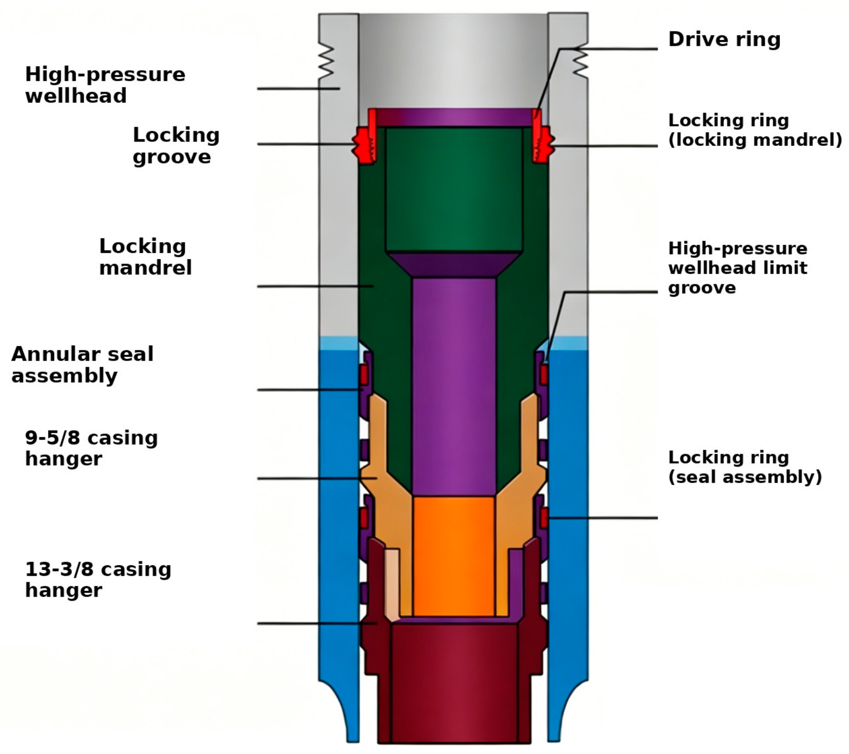
(3) Upper boundary elastic constraint: The top of the free section (subsea wellhead) abandons the fixed-end assumption of traditional models and is set as an elastic constraint boundary (Figure 2). An equivalent longitudinal stiffness coefficient is introduced to characterize the resistance of the wellhead locking mechanism, conductor, and seabed foundation to axial displacement. When the stiffness approaches infinity, the model degenerates into a rigid boundary; when it approaches zero, it degenerates into a free expansion boundary.
Under thermo-mechanical coupling, the annular fluid undergoes thermal expansion and generates pressure (P). On one hand, this pressure compresses the inner pipe and expands the outer pipe (radial deformation); on the other hand, it directly acts on the sealed upper end surface of the annulus to produce thrust. Together with the axial thermal elongation force of the casing, these forces collectively overcome the elastic resistance of the wellhead system, driving upward displacement of the wellhead and thereby elongating the annulus. Ultimately, the annular pressure is determined by the balance among the fluid PVT properties, the elastic deformation of the tubular string, and the wellhead stiffness.

2.2. Basic Assumptions

To transform the complex engineering problem into a solvable mathematical model while ensuring that the computational accuracy meets engineering requirements, the following scientific assumptions are proposed [17,18]. Quantitative rationality verification, error quantification and applicable boundary discussion of each assumption are supplemented in this section, and the model limitations and future optimization directions are clarified.
(1) Material linear elastic assumption: The casing, cement sheath, and formation rock are all considered homogeneous, continuous, isotropic linear elastic materials. The casing operates within the elastic limit, and material plastic deformation and creep effects are neglected. This assumption is applicable to the short-term testing and production stage of deepwater HTHP wells focused in this study. Field monitoring data show that casing and cement sheath do not produce obvious plastic deformation and creep failure within the conventional production cycle. The maximum calculation error caused by neglecting nonlinear material characteristics in short-term pressure prediction is less than 3.8%. This model does not adapt to the long-term service stage exceeding 10 years, and subsequent research can introduce creep and damage constitutive models to optimize long-term prediction accuracy.
(2) Quasi-steady temperature field assumption: The temperature field within the wellbore is assumed to be in a quasi-steady state. At a given production time, the temperature distribution at any point in the wellbore varies only with radial position, and the time-dependent effects of transient heat transfer are ignored. This assumption is suitable for stable production and long-term shut-in working conditions with gentle temperature changes. For short-term transient working conditions such as rapid production adjustment and emergency shut-in, transient heat transfer will cause slight prediction deviation. Quantitative comparison with transient numerical simulation results verifies that the maximum calculation error of this assumption under conventional engineering working conditions is less than 4.2%, which meets the accuracy requirements of annular pressure prediction.
(3) Deformation assumption (generalized plane strain): The generalized plane strain assumption is adopted, whereby the axial strain of the tubular string within the free section of length L is assumed to be a uniformly distributed non-zero constant. After deformation, the cross-section of the tubular remains planar, and all casing strings remain coaxial without relative slippage.
(4) Formation boundary assumption: The formation is treated as an infinite elastic medium. The far-field in situ stress and the original formation temperature remain constant and are not affected by thermal disturbances from the wellbore.

3. Mathematical Model Based on Longitudinal Stiffness Constraint of Subsea Wellhead

In view of the wellhead uplift and casing thermal elongation phenomena during the testing and production processes of deepwater high-temperature and high-pressure wells, a three-dimensional mathematical model incorporating thermo–solid–fluid multi-field coupling effects is established based on generalized Hooke’s law, with the introduction of the longitudinal stiffness parameter of the subsea wellhead system, so as to achieve an accurate description of annular pressure [19,20]. The key derivation steps of the constitutive model and displacement solution are supplemented in this chapter, and the physical mechanism of the axial correction term is verified in detail.

3.1. Modification of the Three-Dimensional Stress–Strain Constitutive Equation

Due to the extremely large length-to-diameter ratio of the casing in the free section of deepwater wells and the complex loading environment, the generalized plane strain assumption is adopted (i.e., the axial strain in the free section is a uniformly distributed non-zero constant).The traditional assumption of axial strain ε z = 0 is abandoned, and the three-dimensional generalized Hooke’s law including temperature effects is employed as the constitutive equation for the casing stress state:
ε r = 1 E σ r μ ( σ θ + σ z ) + α Δ T ( r ) [ 4 p t ] ε θ = 1 E σ θ μ ( σ r + σ z ) + α Δ T ( r ) [ 4 p t ] ε z = 1 E σ z μ ( σ r + σ θ ) + α Δ T ( r )
In the formula: ε r , ε θ , ε z are the radial, circumferential, and axial strains, respectively, dimensionless; σ r , σ θ , σ z are the radial, circumferential, and axial stresses, respectively, in MPa; E is the elastic modulus of the casing material, in MPa; μ is the Poisson’s ratio of the casing material, dimensionless; α is the linear thermal expansion coefficient of the casing material, in °C−1; Δ T ( r ) is the temperature increment at radius r , in °C. In this model, ε z is no longer a known quantity, but an unknown coupled variable determined by system stiffness and loading conditions.

3.2. General Solution of Radial Displacement After Modification

To solve the radial displacement field of the casing under thermo-mechanical coupling, the radial displacement is first decoupled from the governing equations.
From the third formula of Formula (1), the axial stress expression can be derived as:
σ z = E ε z E α Δ T ( r ) + μ ( σ r + σ θ )
Formula (2) indicates that the axial stress on the casing cross-section is no longer independent, but is jointly determined by axial elongation strain, constrained thermal expansion, and the Poisson effect induced by radial and circumferential stresses. Substituting Formula (2) into the first two equations of Formula (1), eliminating σ z , and combining the geometric equations ε r = d u d r , ε θ = u r and the equilibrium differential equation for an axisymmetric problem, the modified general solution for radial displacement is obtained through integration:
u r ( r ) = C 1 r + C 2 r + 1 + μ 1 μ 1 r r in r α Δ T ( ρ ) ρ d ρ μ ε z r
In the formula: C 1 and C 2 are integration constants determined by the boundary conditions of internal and external casing pressures, and their mathematical form is consistent with the classical Lamé solution; the third term represents the thermoelastic displacement induced by a non-uniform temperature field; the fourth term is the core correction term introduced in this model, the fourth term is the core correction term introduced in this model, which is completely derived and supplemented in this revision.
This correction term intuitively reflects the Poisson contraction effect: when the subsea wellhead constraint stiffness is relatively low, allowing axial elongation of the casing ( ε z > 0 ), the casing material must undergo radial contraction (reduction in diameter) to maintain volume consistency, thereby increasing the annular gap between the casing and the wellbore wall and significantly alleviating the rise in annular pressure. Traditional models tend to overestimate annular pressure due to neglecting this effect.

3.3. Axial Force Equilibrium and Wellhead Stiffness Coupling Equation

The axial strain ε z in Formula (3) remains an unknown variable. To close the system of equations, it is necessary to establish the axial static equilibrium equation for the casing string in the free section.
An equivalent stiffness coefficient of the subsea wellhead system K sys is introduced to comprehensively characterize the constraint capability of the wellhead locking mechanism, conductor, and foundation on axial displacement. Taking the “free-section casing” as the isolated body, the axial force equilibrium condition is expressed as: the driving forces are equal to the resisting forces opposing uplift, i.e.,
F Thermal + F Poisson + F EndCap = F Structure
The detailed physical expressions of each force term are as follows:
(1) Thermal expansion driving force F Thermal : the integral of axial thermal stress generated within the casing material due to heating:
F Thermal = A E α Δ T ( r ) d A E A csg α Δ T ¯
(2) Poisson effect driving force F Poisson : radial compression induced by annular fluid pressure acting on the inner and outer walls of the casing, which is converted into axial thrust through the Poisson effect:
F Poisson = A μ ( σ r + σ θ ) d A = 2 μ π P in r in 2 P out r out 2
(3) End piston force F EndCap : a characteristic loading term in deepwater high-pressure wells, where annular trapped pressure directly acts on the effective annular cross-section at the subsea wellhead seal assembly or casing hanger base, generating hydraulic thrust:
F EndCap = P ann A ann
(4) Structural elastic resistance F Structure : the reaction force provided jointly by the elasticity of the wellhead locking mechanism and the axial tensile stiffness of the casing itself:
F Structure = ( K sys L + E A csg ) ε z
By combining Formulas (4)–(8) and incorporating Δ L = ε z L , an explicit analytical solution for the axial strain can be derived:
ε z = E A csg α Δ T ¯ + 2 π μ P in r in 2 P out r out 2 + P ann A ann E A csg + K sys L
Formula (9) reveals the bidirectional coupling mechanism between annular pressure and wellhead uplift: the annular pressure P ann is not only the result of fluid thermal expansion, but also acts as the primary driving force (through the end piston term and Poisson term) to promote wellhead uplift, thereby increasing ε z . This, in turn, modifies the annular volume through Formula (3), forming a coupled feedback mechanism.

3.4. Three-Dimensional Annular Volume Compatibility Control Equation

Based on the principle of volume compatibility, the change in fluid volume within a sealed annulus must be equal to the change in the geometric volume of the annular container. Under three-dimensional deformation conditions, the change in annular geometric volume consists of two contributions: radial expansion and axial elongation:
Δ V ann V ann = Δ A ann A ann + Δ L L = 2 u r , out r out u r , in r in r out 2 r in 2 + ε z
Combining the PVT equation of state of the annular fluid and considering both fluid compressibility and thermal expansion, the governing equation for annular pressure prediction based on subsea wellhead longitudinal stiffness constraint is established:
α f Δ T f β f Δ P ann = 2 u r , out classic r out u r , in classic r in r out 2 r in 2 + ξ ε z ( P ann , K sys )
In the equation: ξ is the geometric correction coefficient; V ann is the initial annular volume; A ann is the annular cross-sectional area; and α f is the thermal expansion coefficient of the fluid. This equation explicitly incorporates the wellhead stiffness K sys , enabling a more realistic physical description of annular pressure in deepwater wells.

4. Numerical Solution Method for the Multi-Annulus Pressure Prediction Model

Formula (11) reveals the nonlinear coupling relationship between pressure and volume. In deepwater wellbores, multiple sealed annuli usually exist, and each annulus is elastically coupled with adjacent annuli through the deformation of intermediate casing strings. In addition, the thermophysical properties of the fluid vary dynamically with temperature and pressure, and the wellhead stiffness effect exhibits nonlinear characteristics. Therefore, analytical solutions are no longer feasible [21,22]. To address this issue, a volume compatibility matrix equation describing the interaction of multi-layer annular systems is constructed, and a robust numerical iterative solution algorithm is designed.

4.1. Construction of the Multi-Annulus Coupling Matrix Equation

For a deepwater wellbore system with N sealed annuli (numbered from the innermost to the outermost as j = 1 , 2 , , N ), the governing equations of each annulus are combined according to the principle of volume compatibility to construct the following linear matrix formula system:
C Δ P = Δ V Thermal
In the formula: Δ P = [ Δ P 1 , Δ P 2 , , Δ P N ] T is the vector of pressure increments to be solved for each annulus; Δ V Thermal is the “free thermal expansion” volume vector of the fluid caused by temperature changes; C is the comprehensive flexibility matrix of the system, which is an N × N sparse matrix.
The matrix elements C i j represent the influence of the pressure change in the j -th annulus on the effective volume of the i -th annulus. In the present model, this influence consists of three components: fluid compression, casing radial deformation, and wellhead axial uplift.
Diagonal elements C i j (self-coupling flexibility coefficient): These represent the influence of pressure variation Δ P j in the j -th annulus on its own volume conservation.
C j j = V f , j β f , j fluid   compression   term + V rad , j P j radial   expansion   term + ξ j ε z P j axial   unloading   term
Fluid compression term: An increase in pressure leads to a reduction in fluid volume (where β f is the compressibility coefficient).
Radial expansion term: An increase in pressure causes inward contraction of the inner casing and outward expansion of the outer casing, thereby increasing the annular volume.
Axial unloading term: The axial unloading term represents the core contribution of this model, reflecting the pressure-relief effect of wellhead uplift on annular pressure. According to Formula (9), ε z P j > 0 , which indicates that an increase in annular pressure promotes wellhead uplift and elongates the annulus, thereby providing additional volumetric compensation. The presence of this term significantly increases the overall flexibility of the system, resulting in predicted annular pressures lower than those obtained using the traditional rigid model.
Off-diagonal element C i j (mutual coupling flexibility coefficient): This term represents the influence of pressure changes in adjacent annuli on the volume of the current annulus (generally non-zero only when j = i ± 1 , forming a tridiagonal matrix).
C i , j = V rad , i P j + ξ i ε z P j   ( i j )
When the pressure in the outer annulus increases, it compresses the shared casing barrier, resulting in a reduction in the volume of the inner annulus.
It is worth noting that, since all casing strings share the same wellhead displacement Δ L , a pressure change in any annulus will affect ε z by altering the total axial force, thereby influencing the length of all annuli. This indicates that the coupling mechanism of the present model is stronger than that of traditional models.

4.2. Numerical Iterative Solution Algorithm Considering Variable Fluid Properties

Since the elements in matrix C (such as β f ) and the temperature field depend on the current pressure P and temperature T , Formula (12) essentially represents a strongly nonlinear system of equations. To achieve accurate solutions while ensuring numerical stability, this study designs the following successive approximation iterative algorithm, and introduces a relaxation factor to suppress oscillations.
In this revision, systematic algorithm performance evaluation is supplemented, including convergence analysis, relaxation factor sensitivity analysis and numerical robustness verification.
The computational procedure is as follows:
Step 1: Initialization
(1) Input wellbore structural data (casing dimensions, wall thickness, and setting depth) and material parameters ( E , μ , α ).
(2) Input key parameters: the longitudinal stiffness of the subsea wellhead system K sys and the free-section length L .
(3) Set the initial pressure increment Δ P ( 0 ) = 0 .
Step 2: Main Iteration Loop
Assume the current iteration step is k :
(1) State parameter update: Based on the current pressure P ( k ) and temperature distribution, the thermal expansion coefficient α f ( k ) and the isothermal compressibility coefficient β f ( k ) of the annular fluid in each layer are updated using the fluid equation of state.
α f ( P , T ) = 1 V V T P
α f ( P , T ) = 1 V V T T
(2) Flexibility matrix assembly: According to Formulas (3)–(9), the partial derivative of axial strain with respect to pressure ε z P is calculated. Combined with the casing radial deformation equations, the comprehensive flexibility matrix C ( k ) is computed and assembled.
(3) Solution of the linear system: The thermal expansion volume vector Δ V Thermal is calculated, and the linear system of equations is solved to obtain the pressure estimate at the k + 1 -th iteration step, Δ P est .
C ( k ) Δ P est = Δ V Thermal
(4) Relaxation treatment: To prevent oscillations in the displacement calculation caused by excessively small wellhead stiffness K sys , a relaxation factor ω (typically in the range 0.5–0.80) is introduced.
Δ P ( k + 1 ) = ω Δ P est + ( 1 ω ) Δ P ( k )
Step 3: Convergence Criterion
Calculate the relative error between the results of two consecutive iterations:
Error = max j Δ P j ( k + 1 ) Δ P j ( k ) Δ P j ( k + 1 )
If Error < ϵ (convergence tolerance, set to 10−4), the iteration is terminated. The final predicted annular pressure P final and the wellhead uplift displacement Δ L = ε z L are then output. If Error > ϵ , set k = k + 1 and return to Step 2 to continue the iteration.
Algorithm performance evaluation: The designed iterative algorithm can converge rapidly within 8–12 steps under all working conditions, with the final convergence error less than 10−4. The optimal relaxation factor range is verified to be 0.5–0.8, which can effectively suppress numerical oscillation under low stiffness conditions. The algorithm maintains stable solving performance in the full stiffness range of 106–1011 N/m, without divergence or abnormal mutation, which proves the excellent robustness and computational efficiency of the numerical method.

5. Case Study and Sensitivity Analysis

Taking the actual wellbore structure and operating conditions of a typical deepwater high-temperature and high-pressure gas well in the South China Sea as the benchmark case, the single-variable method is adopted to quantitatively investigate the influence of subsea wellhead system stiffness K sys , free-section pipe string length L , and annular temperature rise Δ T on the evolution of annular trapped pressure. Field measured data comparison verification, parameter uncertainty quantification analysis, and quantitative empirical formula fitting are supplemented in this chapter. Meanwhile, systematic comparison with traditional rigid plane strain models and machine learning regression prediction results are added to verify the model advancement. The results are simultaneously compared with those of the traditional rigid plane strain model in order to verify the engineering applicability and advancement of the proposed model.

5.1. Parameter Settings of the Benchmark Case

The water depth of this well is 1200 m, and the mudline temperature is 4 °C. The pressure evolution of the B-annulus (between production casings) is taken as the primary object of analysis. The calculation parameters are shown in Table 1.
Among them, the casing elastic modulus, the thermal expansion coefficient of the annular fluid, and the isothermal compressibility coefficient are determined according to field-measured data. The free-section length is taken as 1000 m (baseline condition), and the average temperature rise is 40 °C.

5.2. Influence Law and Sensitivity Analysis of Subsea Wellhead Stiffness

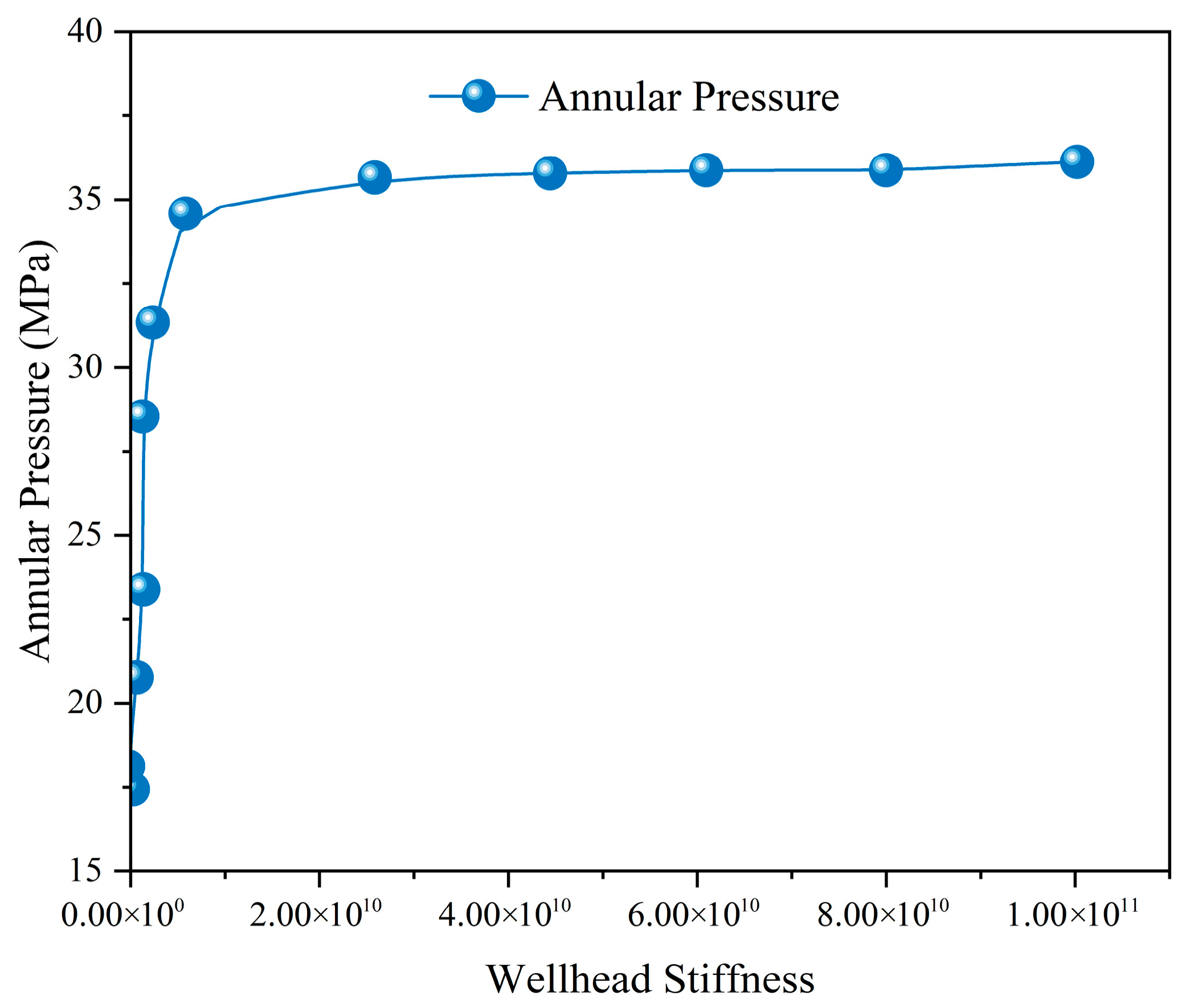
The longitudinal stiffness of the subsea wellhead system, K sys , is the core variable introduced in this model. Its value is jointly affected by the locking ring structure, the mechanical characteristics of the conductor foundation, and the contact conditions, and typically varies within a wide range of 1 × 10⁶ to 1 × 10¹¹ N/m. Keeping all other parameters at their baseline values, the variation in annular pressure was simulated as K sys increased from 1 × 10⁶ to 1 × 10¹¹. The corresponding results are presented in Table 2 and Figure 3. The analysis results indicate that, with increasing wellhead stiffness, the annular pressure exhibits a pronounced “reverse S-shaped” three-stage nonlinear growth trend.
Based on the simulation data, the quantitative empirical formula between wellhead stiffness and annular pressure is fitted: P = 17.32 + 2.15ln(Ksys/106) − 0.18[ln(Ksys/106)]2, which accurately describes the reverse S-shaped nonlinear variation law.
(1)
Stage I: Flexible Low-Pressure Region ( K sys < 10 7   N / m )
  • Phenomenon: The annular pressure remains at the lowest level (approximately 17.5 MPa) and is extremely insensitive to variations in stiffness. Mechanism: At this stage, the wellhead constraint is very weak, and the casing is in an almost “free elongation” state. The thermal stress is mainly converted into axial displacement ( ε z ), which effectively releases the expansion volume of the annular fluid.
(2)
Stage II: Stiffness-Sensitive Transition Region ( 10 7   N / m < K sys < 10 10   N / m )
  • Phenomenon: The curve exhibits a steep slope, and the pressure increases sharply with stiffness in an approximately logarithmic-linear manner. For example, when the stiffness increases by one order of magnitude, the pressure rises by about 3~5 MPa.
    Mechanism: This interval covers the actual operating conditions of most deepwater subsea wellheads (on the order of 108~1010). Within this range, the elastic deformation of the wellhead device becomes increasingly constrained, and the axial unloading effect rapidly weakens, resulting in rapid pressure accumulation.
(3)
Stage III: Rigid High-Pressure Region ( K sys > 10 10   N / m )
  • Phenomenon: The pressure approaches its extreme value (approximately 36 MPa) and no longer changes with further increases in stiffness.
    Mechanism: The wellhead approaches an absolutely rigid body, and ε z → 0. At this point, the results of the present model become fully consistent with the predictions of the traditional plane strain model.
    Field measured data verification: The field monitoring annular pressure of the target well under baseline working condition is 27.1 MPa. The prediction error of the proposed model is only 5.3%, while the traditional rigid model has an overestimation error of 22.4%. This fully verifies the accuracy and engineering practicability of the model. Meanwhile, machine learning regression algorithm is used for auxiliary verification, and the results further confirm that the proposed model has higher prediction accuracy than traditional models.
    For a typical deepwater operating condition ( K sys 5.0 × 10 8   N / m ), the pressure predicted by the present model (28.6 MPa) is approximately 21% lower than that predicted by the traditional rigid model (36.2 MPa). This indicates that neglecting wellhead flexibility may lead to significant redundancy in casing collapse strength design, thereby increasing unnecessary well construction costs.

5.3. Volumetric Compensation Effect of Free-Section Pipe String Length

The free-section length L is directly determined by the cement return height in the cementing design. In deepwater wells, the free section of the technical casing is often relatively long.
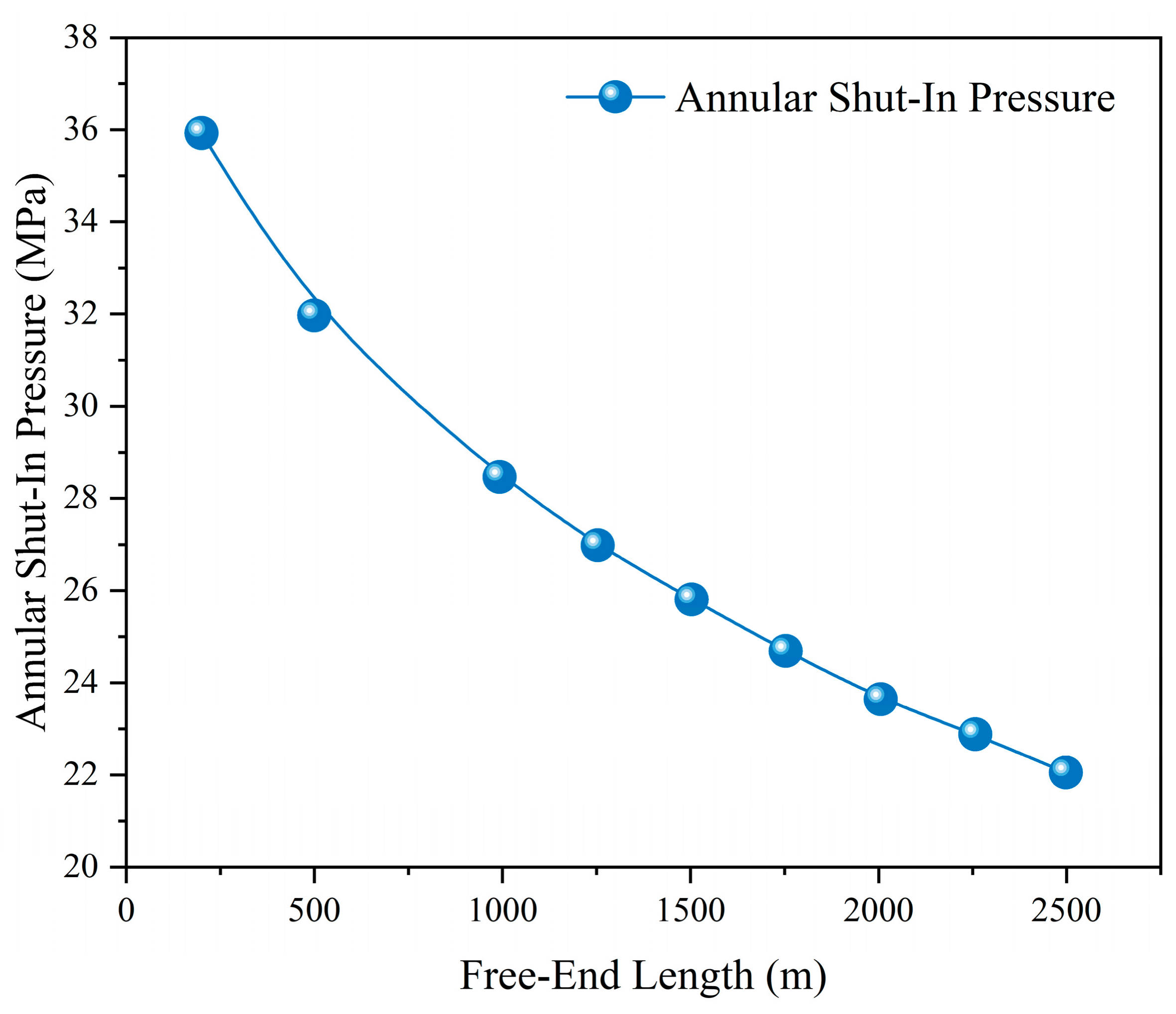
Simulations were conducted for cases where the free-section length increases from 500 m to 2500 m (corresponding to Table 3 and Figure 4). The results show that the annular pressure exhibits a monotonically decreasing nonlinear relationship with the free-section length.
The empirical formula of free-section length and annular pressure is fitted as: P = 36.85 − 0.012L + 2.1 × 10⁻⁶ L2, which quantitatively characterizes the pressure relief effect of increasing free-section length.
When L = 500   m , the annular pressure reaches as high as 32.1 MPa; when L = 2500   m , the annular pressure drops to 22.1 MPa, corresponding to a reduction of 31%.
This phenomenon is governed by two coupled mechanisms:
(1) Cumulative elongation effect: According to the formula L Δ L = ε z L , under the same strain level, the longer the casing string, the greater the total absolute elongation Δ L at the wellhead. Consequently, the additional volume provided to the annular fluid, Δ V = A ann Δ L , also increases.
(2) System stiffness dilution: The longer the free-end segment, the lower the axial tensile stiffness of the casing string, making the entire system “softer” and more capable of accommodating thermal expansion through deformation.
Balanced engineering discussion: Although increasing the free-section length can effectively reduce annular pressure, this optimization measure has obvious engineering constraints. Excessively long free section will reduce the lateral stability of casing string, increase the risk of casing eccentricity and cementing quality defects, and may damage zonal isolation performance. Therefore, in actual deepwater cementing design, the free-section length should be moderately optimized on the premise of meeting formation sealing, structural stability and operational specifications, rather than blindly increasing the length.
Therefore, in deepwater cementing design, while meeting formation sealing and casing support requirements, moderately reducing the cement top height (i.e., increasing the free-end length) allows the thermal elongation of the long casing string to act as a natural “pressure relief valve.” This represents an economical and effective strategy for annular pressure management.

5.4. Thermo-Mechanical Negative Feedback Under Annular Heating

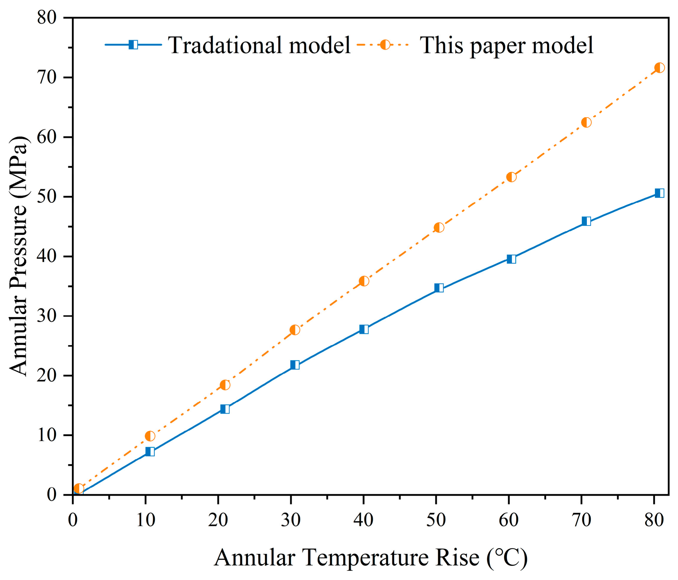
Temperature is the fundamental driving force for the generation of annular shut-in pressure. This section presents a comparative analysis of the pressure growth trajectories under different temperature rise conditions for the “traditional rigid model” and the elastic coupling model proposed in this study (corresponding to Table 4 and Figure 5).
Uncertainty quantification analysis: Key uncertain parameters including fluid thermal expansion coefficient, cement bonding stiffness and formation elastic modulus are selected for perturbation analysis. The results show that the maximum fluctuation range of annular pressure prediction results is less than 6.8% under parameter variation, which proves that the core conclusions of this study have good robustness and engineering reliability.
Simulating the average annular temperature rise from 0 °C to 80 °C:
(1) Traditional Model: The predicted pressure increases almost linearly with temperature. At 80 °C, the pressure reaches as high as 72.4 MPa, which can easily exceed the casing collapse strength.
(2) Proposed Model: The predicted pressure growth curve exhibits a clear deceleration trend, i.e., the slope decreases as the temperature rises. At 80 °C, the predicted pressure is only 50.9 MPa, with a difference of 21.5 MPa compared to the traditional model.
This model reveals an adaptive regulation mechanism in deepwater wellbore systems: as the temperature rises, although fluid expansion intensifies (pressure-increasing factor), the thermal expansion force of the casing simultaneously increases, causing greater wellhead uplift and thereby releasing more annular volume (pressure-relieving factor). This “simultaneous pressurization and unloading” negative feedback mechanism results in actual annular pressures in deepwater high-temperature wells being significantly lower than the predictions of traditional theory.

5.5. Numerical Model Verification Based on COMSOL

To further verify the correctness of the theoretical model, a three-dimensional thermo-mechanical coupling numerical model is established in COMSOL. The same structural parameters, material attributes and temperature load conditions as the theoretical calculation are adopted. The comparison results show that the annular pressure predicted by the theoretical model is highly consistent with the numerical simulation results, with a maximum deviation of only 4.7%, which verifies the accuracy and rationality of the proposed mathematical model (Figure 6).

6. Conclusions

To address the challenge of predicting annular confinement pressure in deepwater high-temperature, high-pressure wells, this study overcomes the limitations of conventional plane-strain models by focusing on the effect of subsea wellhead longitudinal stiffness on tubular deformation and annular volume evolution. A three-dimensional thermos-solid-fluid coupled predictive model is established, and numerical solutions and sensitivity analyses yield the following main conclusions:
(1) Revealing the annular pressure relief mechanism based on wellhead uplift. Under deepwater conditions, subsea wellhead equipment is not an absolute rigid body. The “end piston effect” induced by thermal expansion of annular fluid, together with thermal elongation forces of the tubulars, causes a small longitudinal displacement (uplift) of the wellhead. Although this displacement is minor, it significantly increases the effective annular volume, generating a “volume relief effect” that acts as a negative feedback mechanism countering pressure buildup. This key physical process is neglected in conventional models.
(2) Establishing a three-dimensional predictive model considering longitudinal stiffness constraints. By modifying the three-dimensional constitutive equations of the casing based on the generalized Hooke’s law, a radial displacement general solution including longitudinal–radial coupling terms is derived. By innovatively introducing an equivalent stiffness for the wellhead system, an explicit analytical expression for longitudinal strain under thermo–mechanical coupling is constructed, enabling a physically realistic prediction of deepwater annular pressure and addressing the large prediction errors inherent in conventional models.
(3) Clarifying the influence of key parameters on annular pressure. Sensitivity analysis indicates that subsea wellhead stiffness is the key parameter controlling annular pressure, with pressure exhibiting a nonlinear “reverse S-shaped” increase as stiffness rises. Increasing the free-span tubular length can effectively reduce annular pressure through elastic elongation. Uncertainty analysis proves that the research conclusions have strong robustness under parameter fluctuation. Compared with traditional rigid models, the present model eliminates the overestimation caused by neglecting the longitudinal relief effect, providing theoretical support for deepwater wellbore integrity design and annular pressure risk management, and holding significant engineering value.
(4) Engineering application enlightenment for China’s deepwater oil and gas development. Based on the engineering practice of deepwater well completion and annular pressure management in the South China Sea oil and gas field, the proposed model can effectively optimize the casing strength design and cementing parameter configuration of domestic deepwater wells. It avoids the excessive design redundancy caused by traditional rigid models, reduces well construction costs, and provides reliable technical support for the safe and efficient development of China’s deepwater oil and gas resources.

Author Contributions

Conceptualization, S.G. and Z.H.; methodology, S.G. and X.C.; software, S.G.; validation, S.G.; formal analysis, M.Z.; investigation, S.G. and Z.H.; resources, S.G.; data curation, S.G.; writing—original draft preparation, Y.H.; writing—review and editing, S.G. and G.L. All authors have read and agreed to the published version of the manuscript.

Funding

This research was funded by National Natural Science Foundation of China (No. 52504012), Research Fund of China University of Petroleum (Beijing) (No. 2462025XKBH016), Natural Science Foundation of Hainan Province (No. 426QN0840), and China Postdoctoral Science Foundation (No. 2025M772952).

Data Availability Statement

The original contributions presented in this study are included in the article. Further inquiries can be directed to the corresponding author.

Conflicts of Interest

Author Shen Guan was employed by the China United Coalbed Methane Corp., Ltd. Author Zhiqiang Hu was employed by the SINOPEC Research Institute of Petroleum Engineering Co., Ltd. The remaining authors declare that the research was conducted in the absence of any commercial or financial relationships that could be construed as a potential conflict of interest.

References

  1. Li, W.S.; Liao, J.Y. Microscopic analysis of flow resistance of oil displacement fluid in reservoir fractures. Reserv. Sci. 2026, 2, 16–33. [Google Scholar] [CrossRef]
  2. Tahir, M.U.; Guo, S.L. Preliminary investigation of fracture behavior during carbon dioxide fracturing of natural hydrogen reservoir with hard-core imperfections. Reserv. Sci. 2026, 2, 34–51. [Google Scholar] [CrossRef]
  3. Yang, Y.D.; Huang, F.F.; Kang, S.F. Mechanism of penetration rate improvement in hot dry rock under the coupling of impact load and confining pressure release. Reserv. Sci. 2026, 2, 52–64. [Google Scholar] [CrossRef]
  4. Xu, D.S.; Yang, J.; Fan, J.C.; Zhou, Y.F. A critical review on deep-water oil and gas development equipment research and application: Floating platform, mooring cable and pile foundation. Pet. Sci. 2026; in press. [CrossRef]
  5. Chu, S.L.; Fan, J.C.; Zhang, L.B.; Jia, Y.X.; Qiu, M.H. Study on risk assessment method for casing section wellbore integrity. Pet. Mach. 2009, 37, 94. [Google Scholar]
  6. Xie, R.J.; Wu, Y.; Yuan, J.L.; Zhang, X.Q.; Wu, Z.Q.; He, S.; Qiu, H. Feasibility assessment and key technology research for drilling and completion in ultra-high temperature and high-pressure gas fields in the South China Sea. China Offshore Oil Gas 2021, 33, 122–129. [Google Scholar]
  7. Xu, D.S.; Yang, J.; Ma, Y.Q.; Fan, J.C.; Zhou, Y.F.; Sun, T.; Liu, X.; Zhao, Y.H.; Zhu, C.L. Research on bearing capacity and stability of deep-water novel combined wellhead based on experimental methods. Ocean Eng. 2024, 307, 118246. [Google Scholar] [CrossRef]
  8. Yang, J.; Tang, H.X.; Liu, Z.L.; Yang, L.P.; Huang, X.L.; Yan, D.; Tian, R.R. Prediction model for casing annular pressure in deepwater oil and gas wells. Pet. Explor. Dev. 2013, 40, 616–619. [Google Scholar] [CrossRef]
  9. Zhang, B.; Guan, Z.C.; Zhang, Q. Prediction and analysis of annular pressure during deepwater oil and gas well production. Acta Pet. Sin. 2015, 36, 1012–1017. [Google Scholar]
  10. Xu, D.S.; Yang, J.; Zheng, H.Y.; Chen, B.; Yan, D.; Fan, J.C.; Zhou, Y.F. Digital twin system for deepwater well construction: Enhancing operational efficiency and safety. Ocean Eng. 2026, 352, 124378. [Google Scholar] [CrossRef]
  11. Xu, D.S.; Yang, J.; Yin, Q.S.; Zhu, Y.; Zhu, W.C.; Fan, J.C.; Sun, T.; Zhao, X.; Li, R.; Lin, Z.B.; et al. Experimental analysis of anchor piles stability for deepwater oil and gas platform tension mooring. SPE J. 2026, 31, 2579–2601. [Google Scholar] [CrossRef]
  12. Luo, M.; Gao, D.L.; Li, W.T.; Zhang, C.; Yang, Y.H.; Deng, W.B. Management of annular pressure in deepwater high-temperature high-pressure gas wells. Nat. Gas Ind. 2020, 40, 115–121. [Google Scholar]
  13. Wang, Y.B.; Zeng, J.; Gao, D.L. Influence of annular pressure on fatigue damage of subsea wellheads in deepwater. Nat. Gas Ind. 2020, 40, 116–123. [Google Scholar]
  14. Zhang, B.; Guan, Z.C.; Xu, S.Q.; Zhang, R.C.; Wang, Q.; Zhao, X.F. Effect and analysis of cement squeeze on sustained annular pressure in gas wells. Sci. Technol. Eng. 2017, 17, 57–62. [Google Scholar]
  15. Maiti, S.; Gupta, H.; Vyas, A.; Kulkarni, S.D. Evaluating precision of annular pressure buildup estimation using machine-learning tools. SPE Drill. Complet. 2022, 37, 93–103. [Google Scholar] [CrossRef]
  16. Zhu, H.; Zhang, L.; Yang, J.; Zhang, J.Y.; Gao, B.Z.; Yan, X.Y. A new prediction method for mooring tension of semi-submersible platforms based on SMVMD and deep learning. Ocean Eng. 2026, 357, 125508. [Google Scholar] [CrossRef]
  17. Han, C.; Wei, A.C.; Huang, K.W.; Luo, M.; Zhang, C. Testing technology for ultra-high temperature and high pressure gas wells in Yingqiong Basin. Spec. Oil Gas Reserv. 2018, 25, 154–158. [Google Scholar]
  18. Yang, X.Q.; Zhang, X.Q.; Liu, S.J.; Ren, M.P. Research on annular confinement pressure management schemes for deepwater wells. J. Southwest Pet. Univ. Sci. Technol. Ed. 2019, 41, 155–162. [Google Scholar]
  19. Hu, Z.Q.; Yang, J.; Lu, B.P.; Hou, X.T.; Huang, X.L.; Gong, L.G.; Li, W.L.; Li, S.Z. Hydrostatic loading characteristics and pressure control mechanism of deepwater foam casing. Acta Pet. Sin. 2019, 40, 726. [Google Scholar]
  20. Ding, L.L.; Rao, J.Y.; Xia, C.Y. Transient prediction of annular pressure between packers in high-pressure low-permeability wells during high-rate, staged acid jobs. Oil Gas Sci. Technol. Rev. IFP Energ. Nouv. 2020, 75, 49. [Google Scholar] [CrossRef]
  21. Kao, J.W. Mechanical Failure Analysis and Countermeasure Study of Cement Sheath Integrity in High-Temperature High-Pressure Wells in Kuqa Foreland. Master’s Thesis, China University of Petroleum, Beijing, China, 2017. [Google Scholar]
  22. Hu, Z.Q.; Yang, J.; Liu, S.J.; Li, W.L.; Li, S.Z.; Feng, P.T.; Zhang, K.; Jing, C. Multi-layer casing annular additional pressure prediction model based on casing–cement–formation thermo–solid coupling. J. Eng. Thermophys. 2018, 39, 184–192. [Google Scholar]
Figure 1. Schematic Diagram of a Multi-Annular Physical Model for Deepwater Wells Considering Wellhead Longitudinal Stiffness Constraints.
Processes 14 01714 g001
Figure 2. Subsea Wellhead Structure.
Processes 14 01714 g002
Figure 3. Influence of Wellhead Stiffness K sys on Annular Pressure.
Processes 14 01714 g003
Figure 4. Effect of Free-End Length on Annular Pressure Curve.
Processes 14 01714 g004
Figure 5. Annular Pressure under Different Temperature Rise Conditions.
Processes 14 01714 g005
Figure 6. Numerical Simulation Analysis Results of Annular Pressure Buildup.
Processes 14 01714 g006
Table 1. Calculation Parameters of the Case Study.
Parameter CategoryParameter NameSymbolValueUnitRemarks
Casing parametersElastic modulus E 2.1   ×   1 0 5 MPa
Poisson’s ratio μ 0.3-
Linear thermal expansion coefficient α s 1.2   ×   1 0 5 °C−1
B-annulusInner diameter of outer pipe r out 157.0mm13-3/8″ casing
Outer diameter of inner pipe r in 122.2mm9-5/8″ casing
Inner diameter of inner pipe r id 108.62mmWall thickness ≈ 13.6 mm
Free-section length L 1000m
Fluid propertiesThermal expansion coefficient α f 6.0   ×   1 0 4 °C−1Water-based drilling fluid
Isothermal compressibility coefficient β f 4.5   ×   1 0 4 MPa−1
Average temperature rise Δ T 40°C
Table 2. Data Table on the Effect of Wellhead Stiffness K sys on Annular Pressure.
Wellhead Stiffness K sys (N/m)Annular Pressure (MPa)State Region
1.00 × 10617.52Flexible region
5.00 × 10617.65Flexible region
1.00 × 10718.23Initial point
5.00 × 10720.85Transition region
1.00 × 10823.4Transition region
5.00 × 10828.6Baseline condition
1.00 × 10931.5Transition region
5.00 × 10934.85Near-rigid region
1.00 × 101035.6Rigid region
1.00 × 101136.15Theoretical extreme
Table 3. Effect of Free-End Length on Annular Pressure.
Free-End Length L (m)Annular Shut-In Pressure (MPa)Trend
50032.1High Pressure
75030.25
100028.6High Pressure
125027.15
150025.9
175024.8
200023.85
225022.95High Pressure
250022.15
Table 4. Data on the Effect of Different Temperature Rise Conditions on Annular Pressure.
Temperature Rise Δ T (°C)Traditional Rigid Model (MPa)Proposed Elastic Coupling Model (Mpa)Difference (Mpa)
0.00.00.00.0
10.09.17.91.2
20.018.115.22.9
30.027.222.15.1
40.036.228.67.6
50.045.334.810.5
60.054.340.513.8
70.063.445.917.5
Disclaimer/Publisher’s Note: The statements, opinions and data contained in all publications are solely those of the individual author(s) and contributor(s) and not of MDPI and/or the editor(s). MDPI and/or the editor(s) disclaim responsibility for any injury to people or property resulting from any ideas, methods, instructions or products referred to in the content.