
Article

Safety of Bed-Separation Grouting Filling Mining Under a Gas Station and Its Application
1
College of Energy and Mining Engineering, Shandong University of Science and Technology, Qingdao 266590, China
2
Shanxi Coal International Energy Group Co., Ltd., Taiyuan 030000, China
3
Department of Civil Engineering, Graduate School of Engineering, Kyushu University, Fukuoka 819-0395, Japan
*
Author to whom correspondence should be addressed.
Processes 2026, 14(10), 1632; https://doi.org/10.3390/pr14101632
Submission received: 15 April 2026 / Revised: 11 May 2026 / Accepted: 13 May 2026 / Published: 18 May 2026

Abstract

Bed-separation grouting filling mining is a damage-mitigation mining technology characterized by non-interfering mining and filling operations, low cost, and high efficiency. To recover coal resources from the 3801 working face located beneath a surface gas station in a Shanxi coal mine, this study first analyzed the maximum allowable deformation values for the gas station’s canopy, business hall, and oil storage tanks. Second, the feasibility and safety of bed-separation grouting filling mining at the 3801 working face were investigated using physical similarity modeling and the probability integral method. Finally, a field application of this technology was carried out at the 3801 working face. The results show that: (1) After the successive mining of the 3802, 3803 and 3801 working faces, the No. 17 bed separation was finally preserved above the 3801 working face. It is located in the upper part of the water-conducting fracture zone and has a thick impermeable isolation layer. (2) Physical similarity simulation and numerical simulation (3UDEC) of bed-separation grouting filling mining at the 3801 working face indicate that the underlying strata are effectively compacted after mining, and both overlying strata movement and surface subsidence above the grouting zone are significantly reduced. (3) The probability integral method was adopted to predict surface movement and deformation induced by mining at the 3801 working face (bed-separation grouting filling mining), the 3802 working face (fully mechanized top-coal caving mining) and the 3803 working face (full-seam mining in a single lift). All surface movement and deformation indices satisfy the surface deformation control requirements for the gas station. (4) After completion of the overburden bed-separation grouting filling project at the 3801 working face, the measured surface movement and deformation values during and after mining are all below the allowable deformation limits. No large deformations or cracks occurred in gas station structures including the canopy, business hall and oil tank farm. The protection effect is satisfactory, and the gas station has maintained normal operation throughout the mining period.

1. Introduction

Coal is an important major energy and strategic resource in China [1]. The exploitation of coal resources in China has gradually shifted to the central and western regions. In densely populated and built-up areas, the contradiction between “three-under” mining and the requirements of surface subsidence control and building protection is becoming increasingly prominent [2,3,4]. Filling mining is an important technique for damage-mitigation mining. As a damage-reduction mining technology based on the mechanism of overburden strata movement [5,6], bed-separation grouting mining features a simple system, low initial investment, non-interfering mining and filling operations, and a relatively low cost per ton of coal [7]. In many practical projects in Shanxi, Shandong and other provinces, strata movement and surface subsidence have been effectively controlled [8,9,10]. A gas station is a facility that stores hazardous chemicals [11] and is highly sensitive to surface movement and deformation during the entire mining process. The research and application of building safety protection in grouting mining under gas stations is of great significance for enriching and improving the “three-under” coal mining technology system.
At present, domestic and international scholars have carried out valuable research and practice on bed-separation grouting mining under buildings [12,13,14]. For example, Guo et al. [15] proposed a technology for subsidence control using multi-layer bed-separation grouting in overburden strata for mining in “three-soft” thick coal seams, and successfully applied it to coal extraction under villages at the 22,151 working face in Peigou Coal Mine. Wang et al. [16] developed and applied a “three-step” curtain and bed-separation grouting technique for overburden strata and gobs, realizing bed-separation grouting mining for island working faces beneath villages. Xuan et al. [17] investigated the failure modes and protection criteria of railway tunnels under longwall mining conditions, put forward an overburden isolation grouting filling method for tunnel protection, and successfully implemented grouting mining at a fully mechanized top-coal caving face under a railway tunnel. Han et al. [18] proposed a “four-zone” control model for surface subsidence induced by overburden bed-separation grouting and conducted unilateral open bed-separation grouting mining for protective coal pillars in a coking plant. Cui [19] calculated key parameters including the position of grouting key strata, spacing of grouting boreholes, and grouting pressure for the 2309 and 2307 working faces in Zhaozhuang No. 2 Well, and implemented full-stage grouting filling mining combined with data analysis of mine pressure monitoring and surface subsidence observation. Cheng [20] studied the layout of the first group of grouting boreholes for overburden isolation grouting filling in coal mining under villages near the stopping line, which was successfully applied to the 7226 working face of a mine in Huaibei, realizing coal extraction without village relocation. Li [21] adopted overburden isolation grouting to recover coal resources beneath railway tunnels in the Yangquan mining area. Based on site conditions of the working face, the borehole layout scheme was determined and grouting filling parameters were adjusted on time, achieving effective tunnel protection.
Regarding the deformation control and protection of structures within gas stations, Zheng et al. [22] employed the MetroIn-DPM system to conduct a three-phase deformation monitoring of the gas station canopy. By utilizing measurement data from a theodolite system as an external verification condition, they analyzed the canopy deformation and reinforced the foundation and pillars of the gas station, thereby effectively enhancing its deformation resistance. Cui et al. [23] investigated the causes of deformation in the upper structure of the gas station canopy induced by differential foundation settlement. To address the challenges of construction safety risk management when shield tunneling underpasses an existing gas station, LIU [24] applied risk assessment theory and digital simulation methods. Based on the risk assessment results, a series of risk control strategies were proposed, ultimately forming a comprehensive construction safety risk management system for such projects. He [25] focused on the scenario of a shield machine underpassing a gas station. They primarily collated and comprehensively analyzed existing field settlement monitoring data from areas similar to the gas station region. Subsequently, the FLAC3D6.0 numerical simulation software was utilized to model and simulate the excavation based on the data from the monitored sections, thereby verifying the reliability of using FLAC3D numerical simulation to predict the surface subsidence caused by double-line shield tunneling underpassing a gas station. Furthermore, Wan et al. [26] proposed the key technical points for the implementation of self-monitoring by gas stations and oil depot enterprises.
Scholars both domestically and internationally have conducted extensive meaningful research on bed-separation grouting filling mining of protective coal pillars and the protection of structures within gas stations. However, current research on bed-separation grouting mining primarily focuses on extraction at the periphery of protective pillars, while studies on bed-separation grouting filling mining where the working face directly passes underneath buildings remain limited. In particular, there is a lack of research concerning bed-separation grouting mining under high-risk structures such as gas stations. Therefore, taking the bed-separation grouting mining under a gas station at the 3801 working face of a coal mine in Shanxi as a case study, this paper analyzes the maximum allowable deformation values for the gas station’s canopy, business hall, and oil storage tanks. Furthermore, by combining physical simulation, numerical simulation and the probability integral method, the feasibility and safety of bed-separation grouting filling mining at the 3801 working face under the gas station were investigated. Finally, the engineering practice of bed-separation grouting mining at the 3801 working face was implemented.

2. Engineering Background

A mine located southwest of the urban area of Changzi County, Shanxi Province, is a thermal coal mine under Shanxi Coking Coal Group. Coal reserves trapped beneath structures (“three-under” coal) account for approximately 50% of the mine’s total reserves, which severely restricts the sustainable development of the mine. The 3801 working face is situated in the eighth panel of the mine, with a strike length of 1229 m and a face length of 250 m. The average burial depth of the coal seam is 521 m; the average coal seam thickness is 5.8 m, the thickness of the unconsolidated layer is about 193 m, and the bedrock thickness is approximately 345 m. The average dip angle of the coal seam is 5°, and the reserves of the working face are about 2.64 million tons. To the west of the 3801 working face lie the goaf of the 3802 working face (completed in March 2021) and the goaf of the 3803 working face (completed in July 2022). The surface–underground layout plan of the 3801 working face is shown in Figure 1. The borehole log of the working face area is shown in Figure 2. The lithology of boreholes in the 3801 working face area is listed in Table 1.
There is a gas station located in the middle of the 3801 working face. According to its total storage capacity and individual tank volume, it is classified as a Class II gas station with high safety and protection requirements. The horizontal length of the gas station along the working face is approximately 75 m, and its horizontal distance from the northernmost edge to the surface projection of the initial cut is about 821 m. The gas station traps approximately 1.65 million tons of coal resources in the 3801 working face, accounting for 60% of its designed total reserves. To recover these coal resources, the 3801 working face plans to adopt bed-separation grouting filling mining to control surface subsidence and protect the surface structures of the gas station.
The bed-separation grouting mining of the 3801 working face primarily faces the following challenges: (1) The mine lacks systematic surface rock movement observation results, and the surface subsidence laws and rock movement parameters associated with bed-separation grouting filling mining, in particular, remain unclear. (2) Structures within the gas station have already been affected by the prior mining of the 3802 and 3803 working faces, increasing the difficulty of building protection. (3) The gas station’s oil storage tanks are hazardous chemical storage facilities, which are highly sensitive to deformation and require stringent surface subsidence control.

3. Protection Requirements for Gas Station Buildings

Oil storage tanks are typically damaged by geometric deformation and stress concentration caused by uneven foundation settlement, which may lead to accidents. According to field measurement data from 100 oil tank projects cited in Ref. [28], the maximum allowable differential settlement of the tank foundation is 4 mm, corresponding to a surface tilt value of 4 mm/m. For the business hall, in accordance with “Specifications for Coal Pillar Setting and Mining Under Buildings, Water Bodies, Railways and Main Roadways”, damage to Grade II can be repaired via simple maintenance or requires no repair. Therefore, the Grade II building damage standard is adopted as the allowable deformation limit for the business hall: −4.0 mm/m ≤ horizontal deformation ≤ 4.0 mm/m, −0.4 × 10⁻³/m ≤ curvature ≤ 0.4 × 10⁻³/m, −6.0 mm/m ≤ tilt ≤ 6.0 mm/m. According to the lateral displacement grade evaluation criteria for non-load-bearing structures specified in the Standard for “Appraisal of Civil Building Reliability” (GB50292-2015) [29], the maximum lateral displacement at the vertex of the canopy structure shall not exceed H/150. The maximum allowable lateral displacement at the vertex of the gas station canopy is approximately 47.6 mm, equivalent to a surface tilt value of 47.6 mm/m.

4. Similar Simulation Study on Bed-Separation Grouting Filling Mining in 3801 Working Face

4.1. Physical Simulation Study on Bed-Separation Development of 3801 Working Face

In order to ensure smooth implementation of bed-separation grouting filling at the 3801 working face, a physical simulation test was conducted based on the geological and mechanical parameters and mining engineering design of the 3801 working face. The test was carried out on a 2D physical similarity simulation test bench at Shandong University of Science and Technology, with dimensions of 3 m (length) × 0.3 m (width) × 2 m (height). Ignoring the influence of strata dip angle, physical simulation models for the 3801, 3802 and 3803 working faces were constructed according to the typical mining section. The parameters of the physical similarity model are selected as follows:
Given that the dimensions of the 2D physical similarity simulation test bench are 300 cm × 30 cm × 200 cm, to simultaneously accommodate the 3801, 3802, and 3803 working faces along the dip direction, the geometric similarity ratio of the physical simulation is determined as follows:
C l = Y m : Y P = 1 : 300
In this equation, Y m is the dimension of the model, m; Y P is the dimension of the prototype, m.
Time similarity constant: As the mining-induced area continuously changes during the advance of the working face, the physical similarity model is dynamic and must satisfy the time similarity requirement. The calculation formula is as follows:
C t = T m : T P = C l
In this equation, T m is the time of the model, s; T p is the time of the prototype, s. The bulk density similarity ratio is as follows:
C γ = γ m : γ P = 3 : 5
In this equation, γm is the bulk density of the model, g/cm3; γp is the bulk density of the prototype, g/cm3.
According to the fundamental formulas of the similarity principle, the similarity ratio for stress and various strengths is as follows:
C σ = C γ × C l = 1 : 500
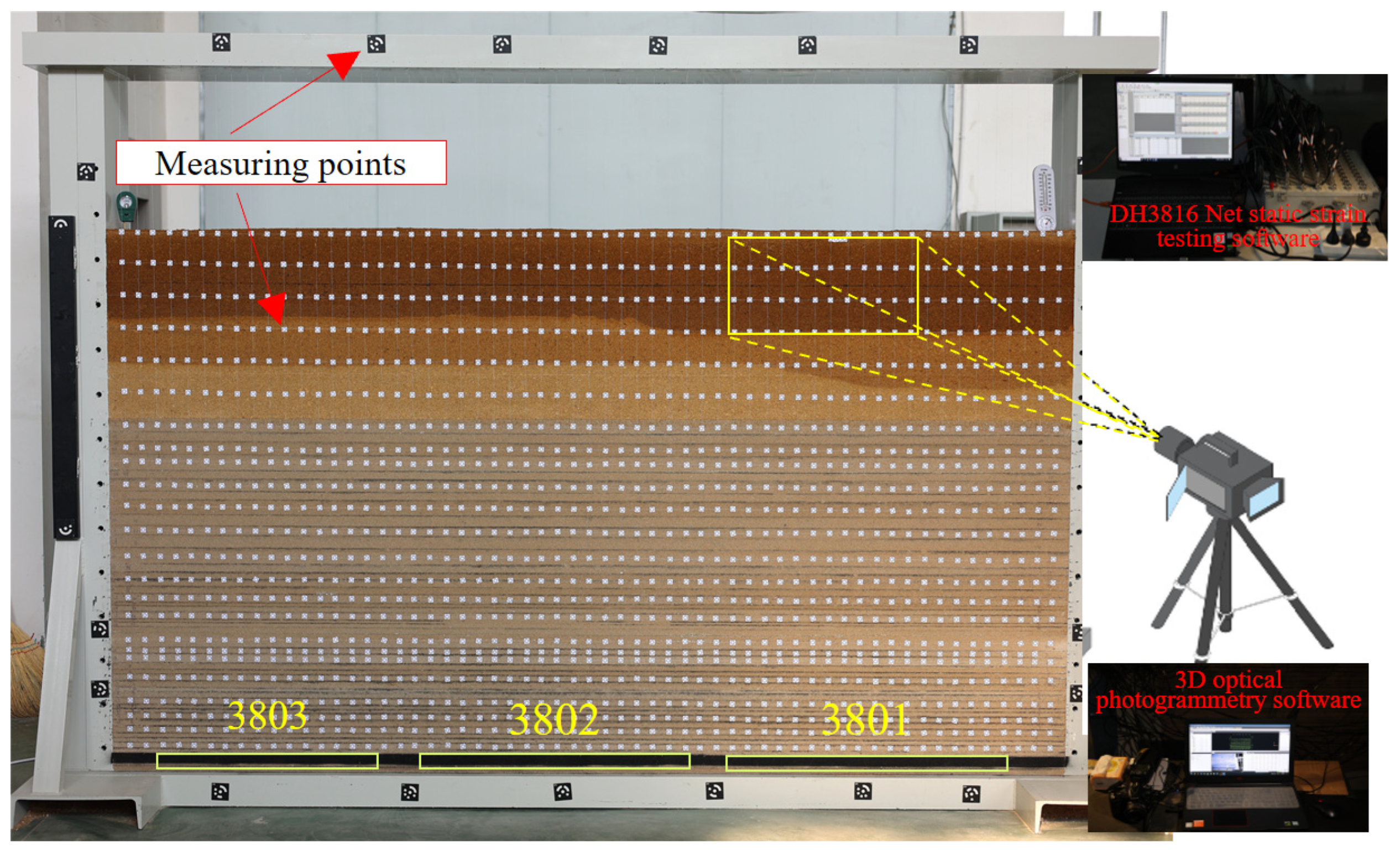
Since the physical similarity model extends up to the surface, there is no need to apply vertical pressure. Additionally, as the simulated strata have no horizontal tectonic stress, no horizontal pressure is required. Therefore, there is no need to select external force similarity conditions. For the section of the model corresponding to the unconsolidated layer, a mixture of sand and sawdust at a mass ratio of 10:1 is laid, ensuring that its bulk density meets the similarity ratio requirements. The model was used to simulate sequential mining of the 3802, 3803 and 3801 working faces, and a 3D optical photogrammetry system was applied to monitor the movement and deformation law of overburden strata. The experimental model is shown in Figure 2. In the test, the 3802 working face was mined first; mining of the 3803 working face began after the model was stable. Finally, the 3801 working face was mined after the model induced by 3802 and 3803 mining had stabilized.
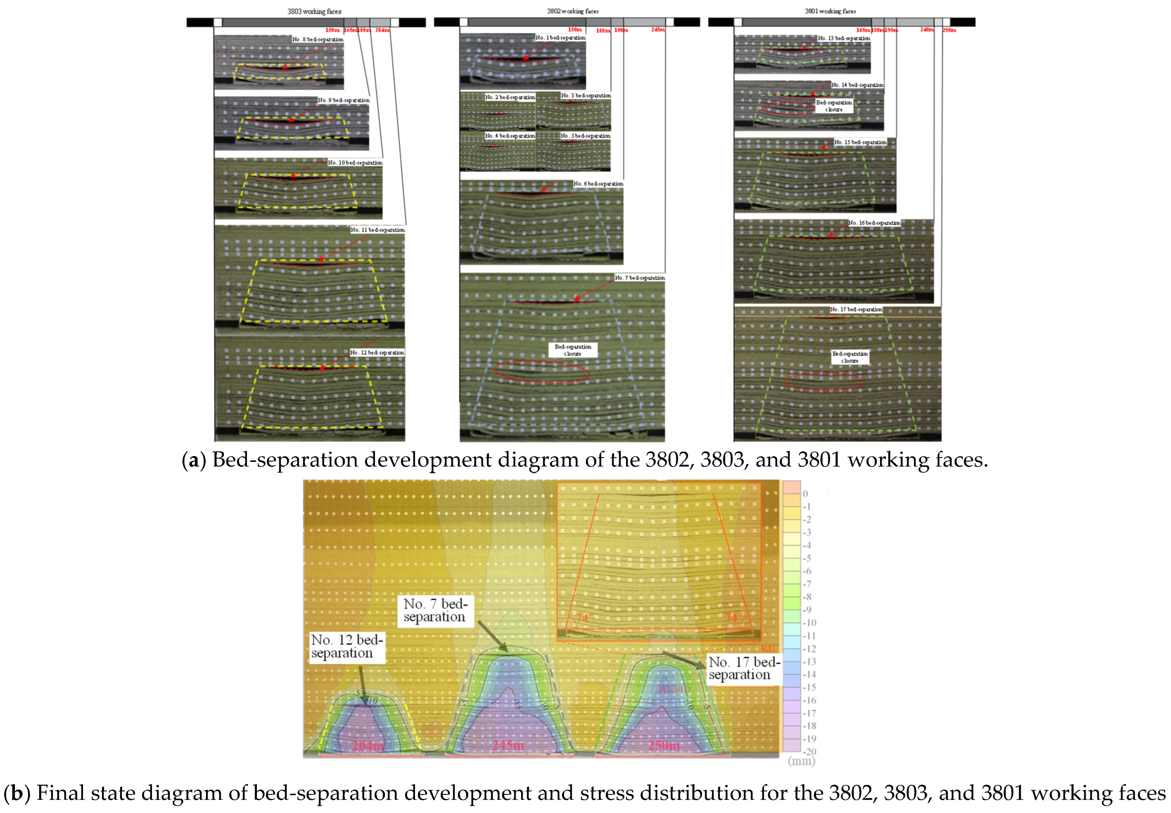
The contour plots of overburden movement and vertical displacement after the sequential mining of the 3802, 3803, and 3801 working faces are shown in Figure 3. During the mining process, a total of 17 bed separations were generated and numbered chronologically. Most of these separations closed as the overlying strata settled. Following the completion of all working faces, only the No. 17 bed separation remained in the 3801 working face. This separation is characterized by an “inverted triangle” geometry, located at a vertical distance of 172.5 m above the coal seam. It has a maximum opening of 2.00 m, a width of approximately 135 m, and a rock fracture angle of 74°. The overlying stratum of the No. 17 bed separation is an extremely thick and hard medium-grained sandstone. According to the Key Stratum theory [1], this horizon is classified as a sub-key stratum, which creates the necessary geological conditions for the stable existence of the No. 17 bed-separation space. The No. 17 separation layer remains intact with the adjacent overlying and underlying strata, showing no significant cracks or fractures. This integrity provides an effective isolation layer that prevents grout leakage or migration. Furthermore, field measurements at 150 m south of the 3801 air intake crossheading’s cut-out indicated that the height of the water-conducting fracture zone is 69.1 m. According to the literature [30], a “maintenance zone” with a thickness of two to six times the coal seam thickness is required between the grouting horizon and the fracture zone. Taking a safety factor of 6 and a coal thickness of 6.6 m, the required isolation thickness is 39.6 m. Consequently, the grouting layer should be at least 108.7 m (69.1 m + 39.6 m = 108.7 m) above the roof. The No. 17 separation layer, situated at 172.5 m, clearly satisfies the technical requirements for bed-separation grouting.

4.2. Physical Simulation Study on Bed-Separation Grouting Filling Mining at the 3801 Working Face

(1)
Design of the Physical Simulation Model for Bed-separation Grouting Filling Mining
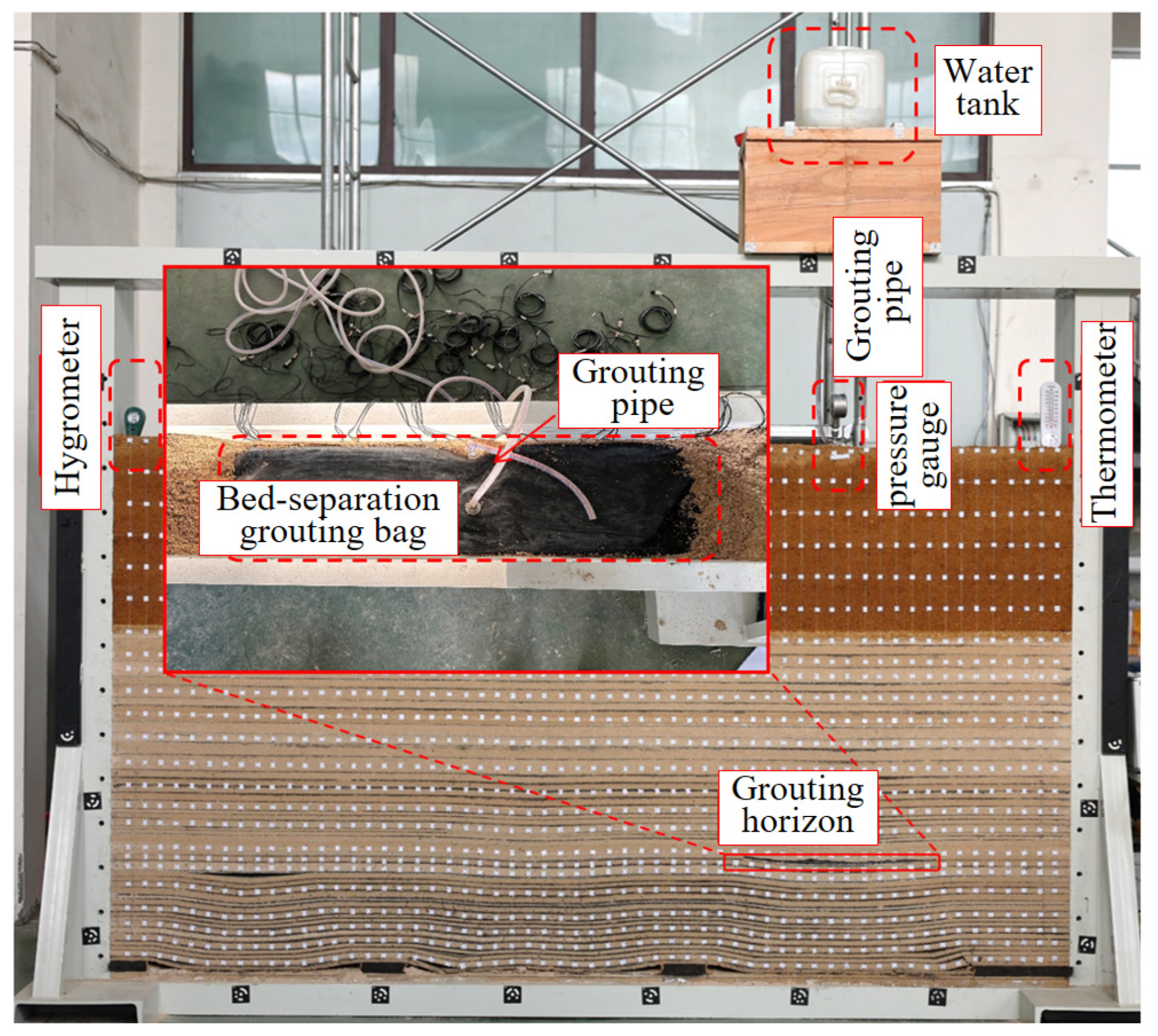
The strata configuration and working face layout of the physical similarity model for the bed-separation grouting in the 3801 working face were consistent with Section 4.1. For the grouting simulation, a self-made PVC plastic grouting bag (1.2 m long and 0.3 m wide) was pre-laid at the No. 17 bed-separation position of the 3801 working face, with the grouting pipe connected to the model surface. Simultaneously, a digital pressure gauge was installed on the surface to monitor the grouting pressure, and the water pipe and valve were connected to the upper tank of the test bench to pre-set the grouting volume. When the 3801 working face was mined to the 17th bed-separation space, the valve was opened for grouting. Once the grouting pressure and the rock layer became stable, the process was considered complete. The physical similarity simulation experiment model for the bed-separation grouting filling in the 3801 working face is shown in Figure 4. The experimental sequence involved mining the 3802 and 3803 working faces first (consistent with Section 4.1). After the model stabilized, the bed-separation grouting filling mining of the 3801 working face was conducted.
(2)
Overburden movement characteristics and ground subsidence control effects
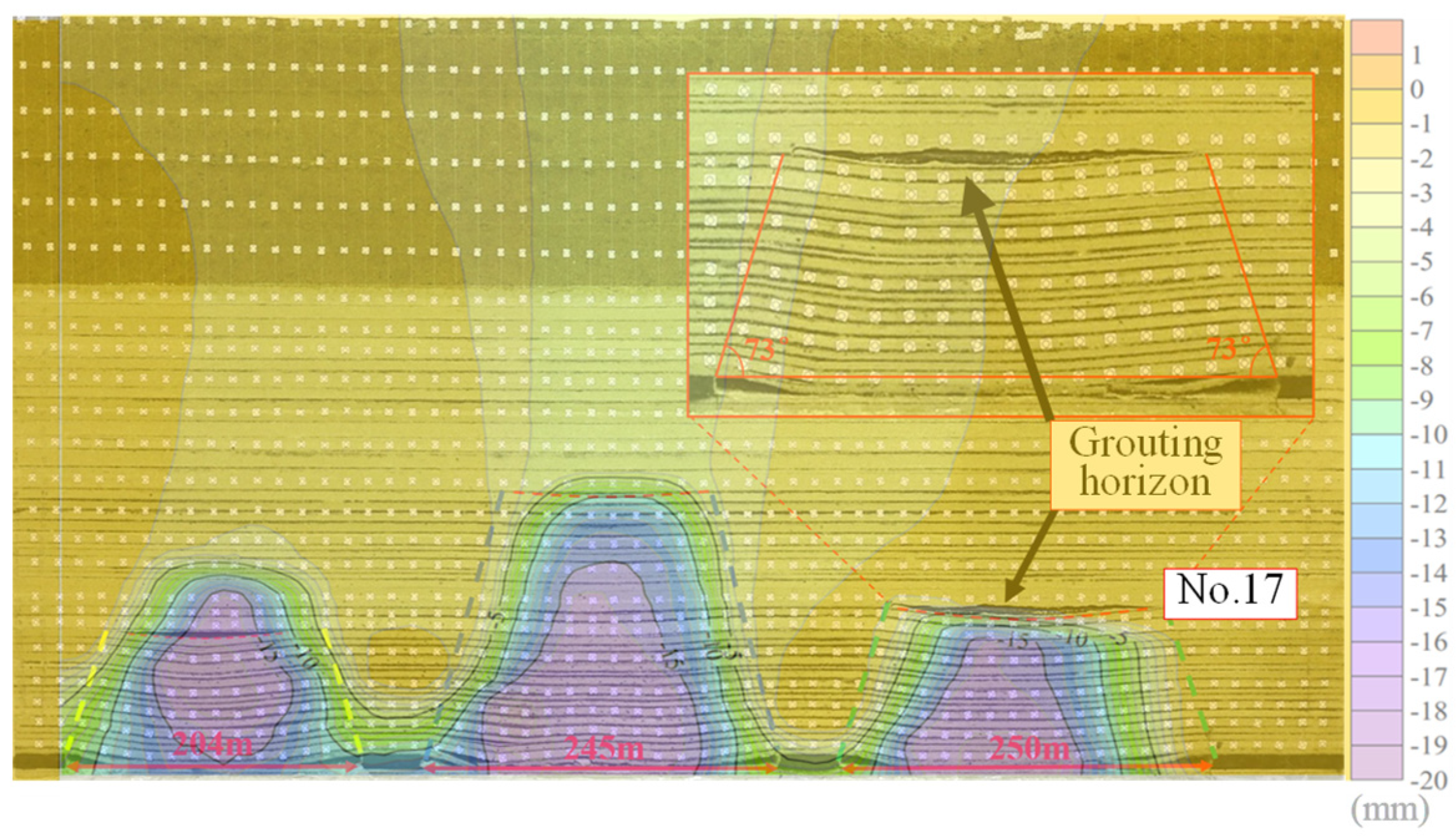
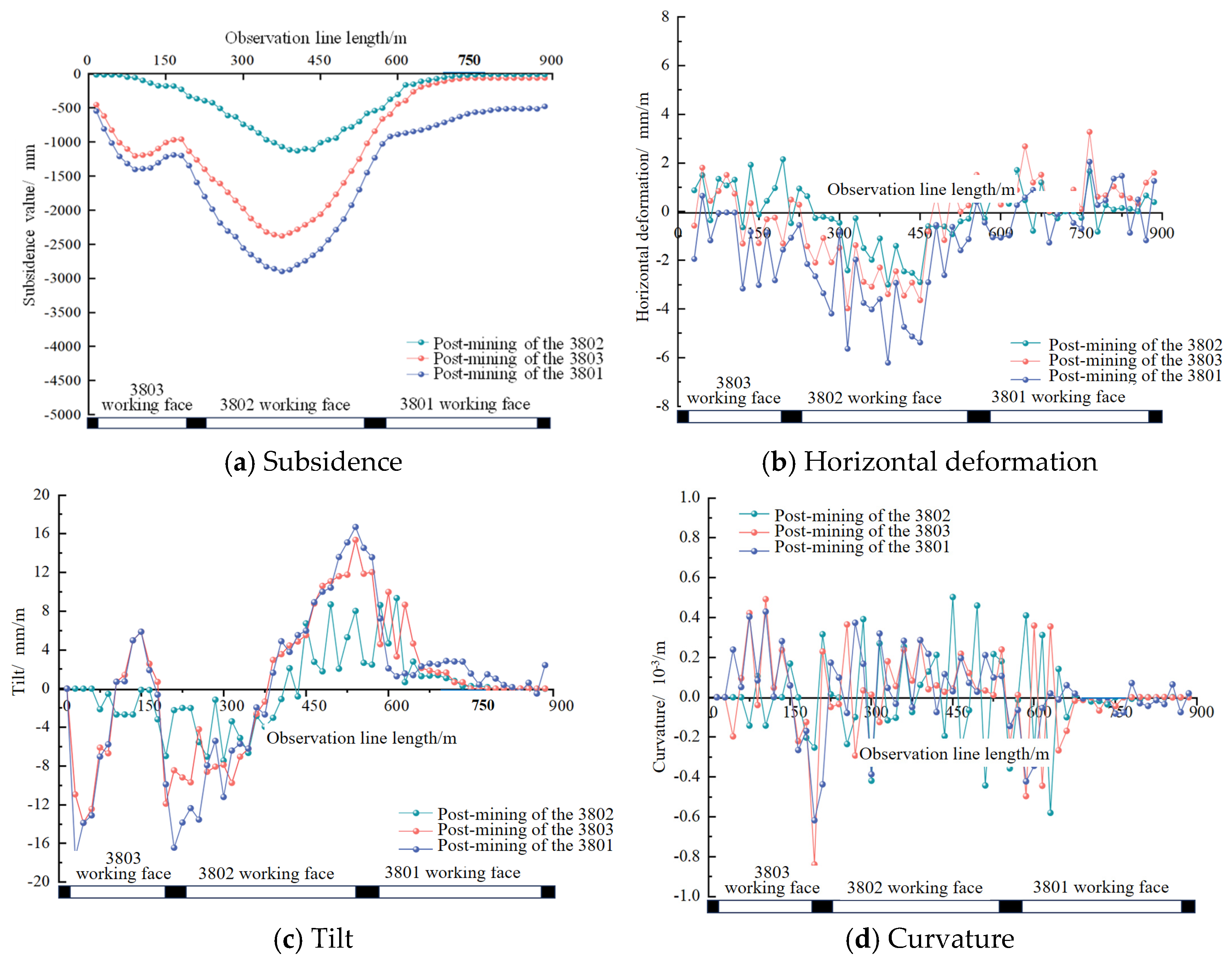
During the bed-separation grouting mining of the 3801 working face, a constant water pressure was maintained within the grouting bag. As the bed separation began to form, the pressure decreased sharply, and the water valve was opened to initiate the grouting process. Due to the expansion of the slurry and its upward support and downward pressure effects, the rock layers between the grouting horizon and the coal seam were further compacted, leading to a continuous increase in the compaction area. Simultaneously, no significant subsidence occurred in the strata above the grouting layer, and no new separation spaces were observed at the upper interfaces. The contour plots of overburden movement and vertical displacement after grouting are shown in Figure 5. The strata below the bed separation were effectively compacted; the final grouting separation opening was 6.56 m, with a width of approximately 172.5 m and a rock fracture angle of 73°. The size of the bed separation here is larger compared to that in the previous section, primarily due to the expansion effect of bed-separation grouting on the separation space. Compared to the simulation results without grouting, the strata movement and surface subsidence above the grouting layer were significantly reduced. Based on the monitoring data from the model, the surface movement and deformation curves for the 3801 working face are presented in Figure 6. The maximum subsidence value at the gas station under grouting conditions was approximately −748.53 mm. The maximum horizontal deformation, curvature, and tilt were 1.266 mm/m, −0.08 × 10⁻³/m and 2.86 mm/m, respectively. These physical simulation results demonstrate that bed-separation grouting filling mining in the 3801 working face can effectively control surface subsidence and ensure the structural safety of the gas station.

4.3. Numerical Simulation Study on Bed-Separation Grouting Filling Mining in the 3801 Working Face

(1)
Numerical model of bed-separation grouting filling mining
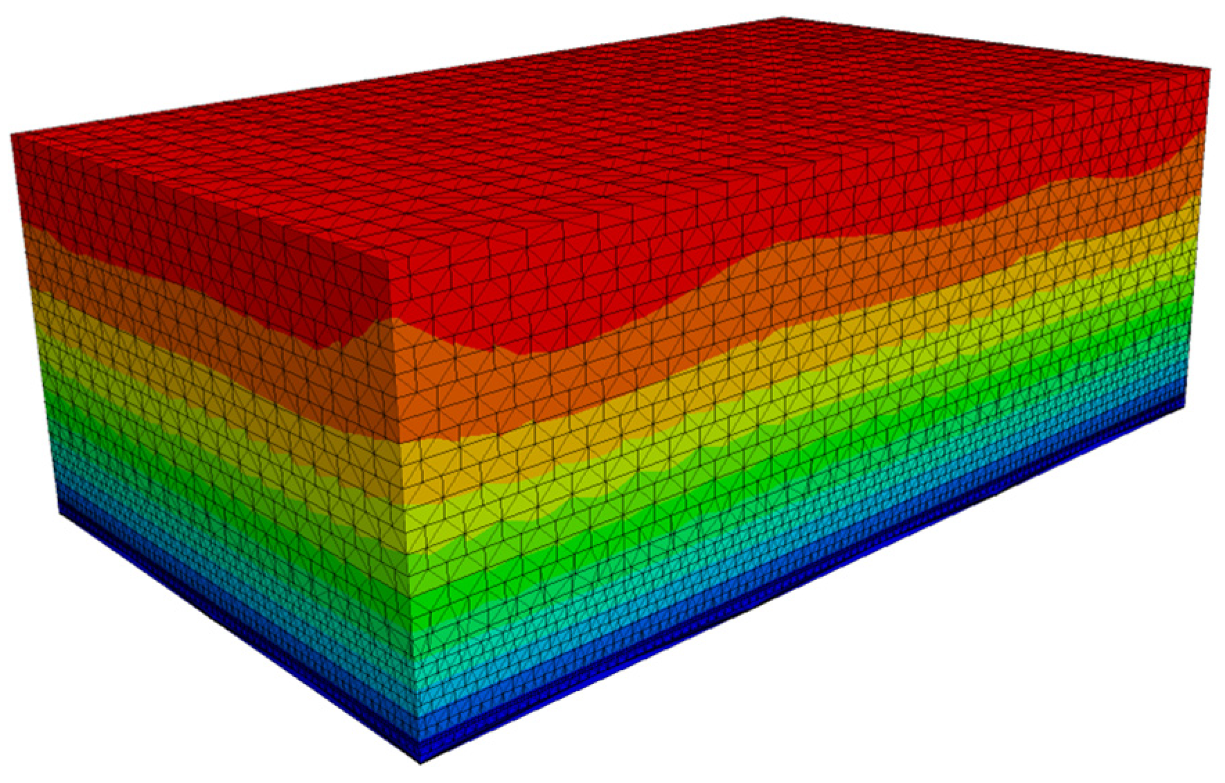
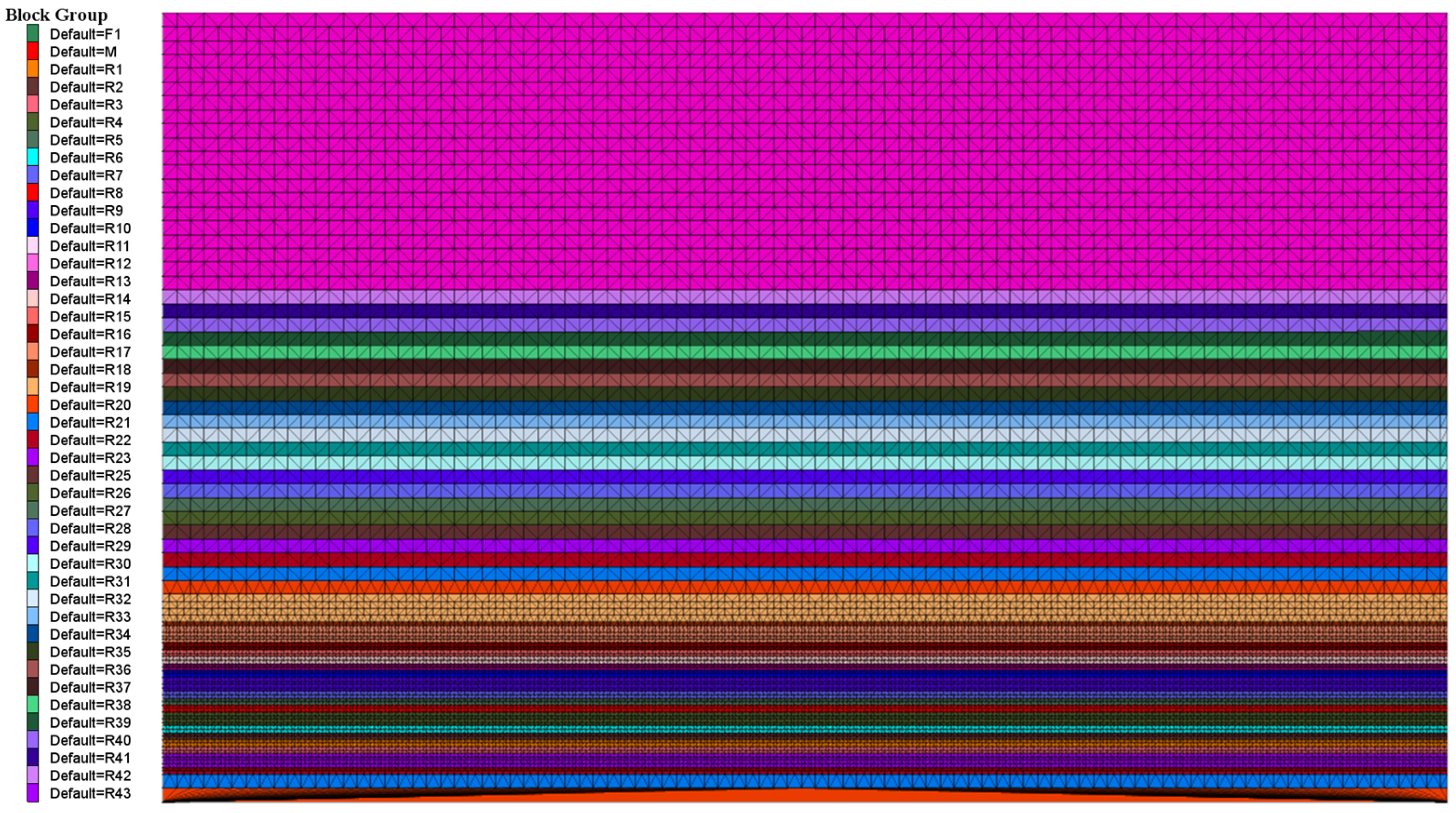
Based on the actual geological conditions of the 3801 working face, 3DEC7.0 numerical simulation software was used to establish a three-dimensional model, neglecting the influence of the strata dip angle. The model dimensions are 1395 m × 832.5 m × 513 m, as shown in Figure 7. To improve the accuracy of the overlying strata subsidence simulation, the mesh density was adjusted: the grid is denser near the coal seam and sparser in the strata further away, as shown in Figure 8. The model extends to the surface, where the upper boundary is defined as a free boundary, while the front, rear, left, right, and bottom boundaries are fixed. Referring to the research results of many scholars on building foundation pressure in the early stage, it is known that the building foundation pressure is generally in the range of 100–400 kPa. In order to better simulate the pressure effect of buildings (structures) on the ground surface in gas stations, a vertically distributed load of 100 MPa is applied at the top of the model, with the position and area consistent with the actual position and area of the gas station. This load is further amplified compared to the actual load, to better illustrate the surface movement and deformation under the combined influence of foundation load and mining.
Both the rock strata and joints follow the Mohr–Coulomb constitutive model. Since the fly ash grout lacks cementation and primarily provides support through compaction, the Double-Yield constitutive model was adopted for the grouting body. According to the engineering design, the grouting-to-mining ratio (Volume ratio) was set to 0.65. The basic parameters of the Double-Yield constitutive model measured through laboratory experiments are shown in Table 2. The simulation sequence involved mining the 3802 and 3803 working faces first. Once the model stabilized, bed-separation grouting filling mining was conducted at the 3801 working face. Observation lines were established on the surface to extract data for analyzing the subsidence reduction effect and the stability of the gas station.
(2)
Overburden movement characteristics and surface subsidence control effects
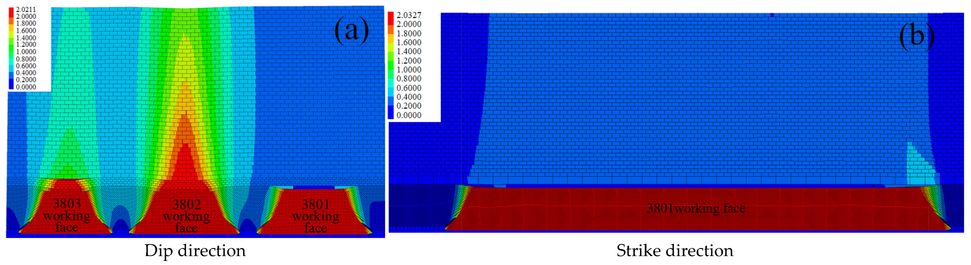
The contour plots of overburden movement after bed-separation grouting filling mining in the 3801 working face are shown in Figure 9. The grouting body is well-compacted within the strata, with a height of 7.2 m, a dip length of 190.35 m, and a strike length of 1169.1 m. The dip profile indicates that the overlying strata are effectively supported after grouting, which prevents the displacement from the 3802 working face from extending into the 3801 area. Consequently, the displacement of the strata above the grouting layer is significantly reduced. The surface movement and deformation after the completion of bed-separation grouting filling mining in the 3801 working face are shown in Figure 10. After mining, the maximum subsidence value in the surface gas station area is 794.95 mm. Specifically, the maximum horizontal deformation in the dip and strike directions is 1.91 mm/m and −0.033 mm/m, respectively; the maximum tilt deformation in the dip and strike directions is 2.06 mm/m and −0.305 mm/m, respectively; and the maximum curvature deformation in the dip and strike directions is 0.0205 × 10⁻³/m and −0.0211 × 10⁻³/m, respectively. The numerical simulation results demonstrate to a certain extent that the implementation of bed-separation grouting filling mining in the 3801 working face can effectively control surface subsidence and protect the safety of surface gas station structures.

5. Surface Movement and Deformation Prediction for Bed-Separation Grouting Filling Mining in the 3801 Working Face

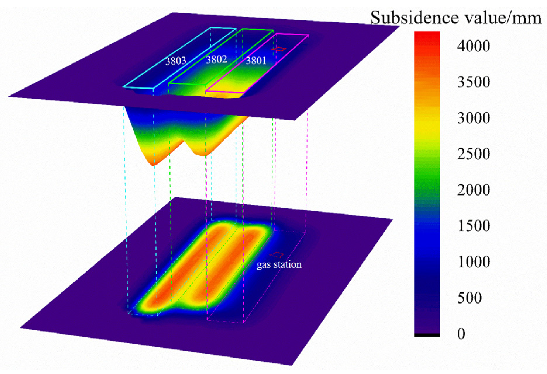
To further verify the stability and safety of the surface gas station following the bed-separation grouting filling mining of the 3801 working face, the probability integral method was employed to predict surface movement and deformation after mining the 3801 working face (bed-separation grouting filling mining), the 3802 working face (fully mechanized top-coal caving mining), and the 3803 working face (full-seam mining). Since systematic strata movement observation data for the specific coal mine were unavailable, the parameters for the 3802 and 3803 faces were selected based on adjacent coal mines. Engineering practice indicates that the surface subsidence coefficient can be controlled within 0.15 using bed-separation grouting. Early observation results from the mine’s 3501 working face showed a subsidence coefficient of 0.09 with a grouting-to-mining ratio of 0.49. The designed grouting-to-mining ratio for bed-separation grouting in the 3801 working face is 0.6. Theoretically, a higher grouting-to-mining ratio yields better surface subsidence control, corresponding to a superior subsidence reduction effect for the 3801 working face. However, when predicting the surface movement and deformation for the bed-separation grouting filling mining of the 3801 working face, a conservative subsidence coefficient of 0.1 was selected to ensure a safety margin. The specific calculation parameters for surface movement and deformation are summarized in Table 3.
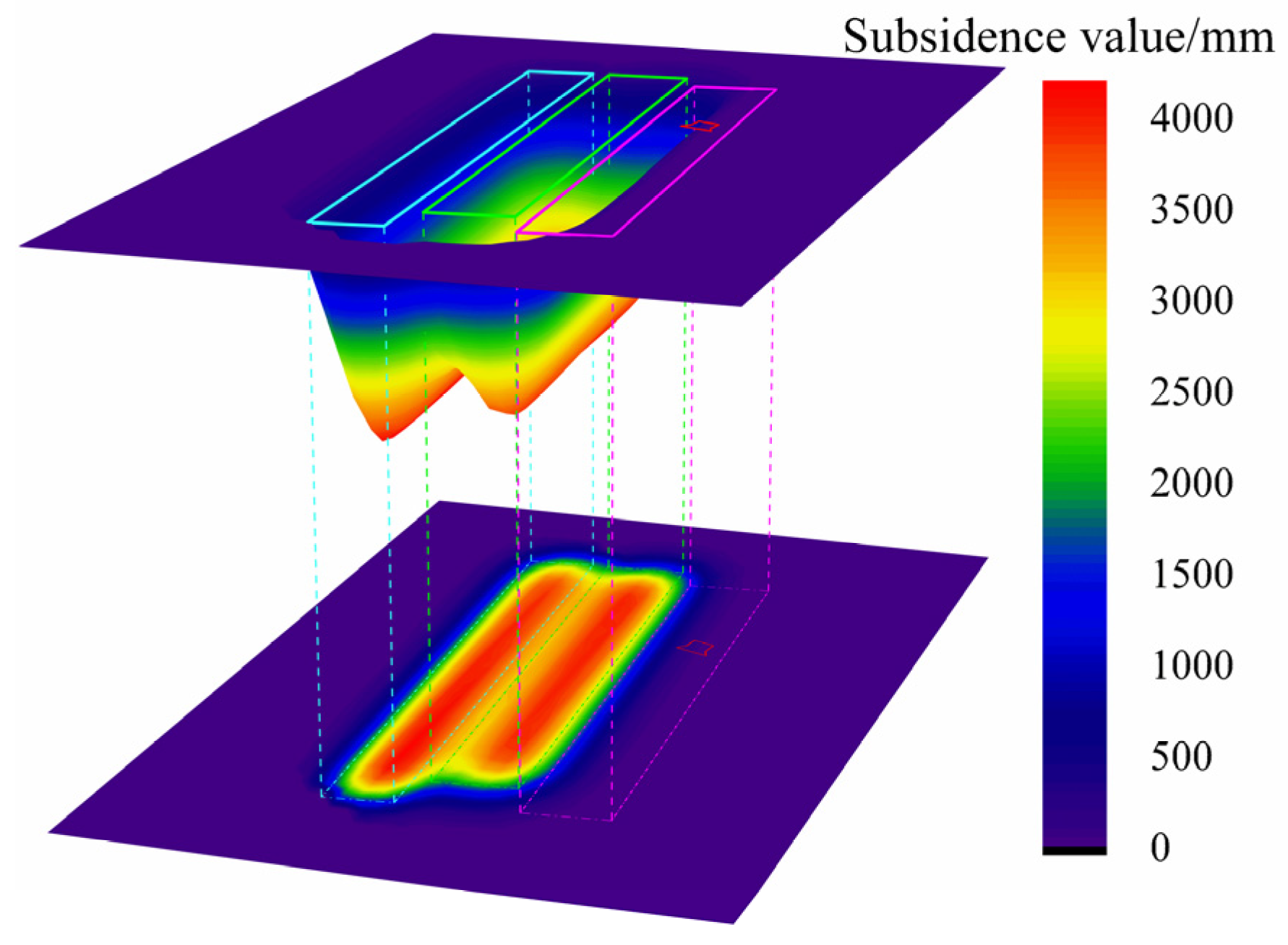
As shown in Figure 11, following the mining of the 3801, 3802, and 3803 working faces, the maximum subsidence in the gas station area is 928 mm. In the north–south direction, the horizontal deformation, curvature, and inclination range from −0.05 to 0 mm/m, −0.001 to 10−3/m, and 0 to 0.4 mm/m, respectively. In the east–west direction, the corresponding values are −1.0 to 3.7 mm/m, 0 to 0.07 × 10⁻³/m, and −5.1 to 2.8 mm/m. The maximum inclination in the oil tank area is −3.6 mm/m, all of which satisfy the deformation control requirements for protecting the gas station structures.
Based on the above analysis, the 3801 working face meets the criteria for implementing bed-separation grouting filling mining. The surface movement and deformation results—obtained via physical simulation, numerical simulation, and the probability integral method—consistently meet the protection standards for the gas station. Therefore, it is technically feasible to carry out bed-separation grouting filling mining in the 3801 working face.
In summary, the physical simulation results indicate that the 3801 working face possesses the necessary conditions for bed-separation grouting filling mining and is suitable for its implementation. Although the obtained surface subsidence data are relatively small due to scaling effects and manual operational errors, they still demonstrate, to a certain extent, that the bed-separation grouting filling mining of the 3801 working face is safe and feasible. To better quantitatively analyze the surface subsidence control effect, numerical simulations were further conducted. The results reveal that, under the required designed grouting-to-mining ratio, the surface movement and deformation within the gas station area meet the protection requirements for its buildings and structures. Finally, to further verify the feasibility of the operation, the probability integral method was employed to predict macroscopic surface movement and deformation. By deliberately selecting a conservative (larger) subsidence coefficient to ensure an adequate engineering safety margin, the predicted values were relatively larger, yet they still satisfied the protection requirements for the gas station’s buildings and structures. Therefore, the implementation of bed-separation grouting filling mining in the 3801 working face is highly feasible.
Note: The surface movement and deformation obtained in this section differ significantly from those in the physical and numerical simulations discussed in Section 4. The primary reasons are as follows: First, due to the scale effect in the physical simulation, the simulated rock layers exhibit relatively weak tensile strength and poor bending–subsidence performance, leading to smaller surface movement and deformation. Second, because fixed boundaries were employed in the similarity simulation, the bending and subsidence of the central rock layers were constrained to some extent, also resulting in smaller deformation values. Therefore, in this section, to further clarify the safety of bed-separation grouting filling mining beneath the gas station, the subsidence coefficient was intentionally increased during the prediction using the probability integral method, leading to larger predicted results. Considering these three methods comprehensively, bed-separation grouting filling mining beneath the gas station is determined to be feasible.

6. Engineering Practice of Bed-Separation Grouting Filling Mining in the 3801 Working Face

6.1. Implementation of Bed-Separation Grouting Filling Mining in the 3801 Working Face

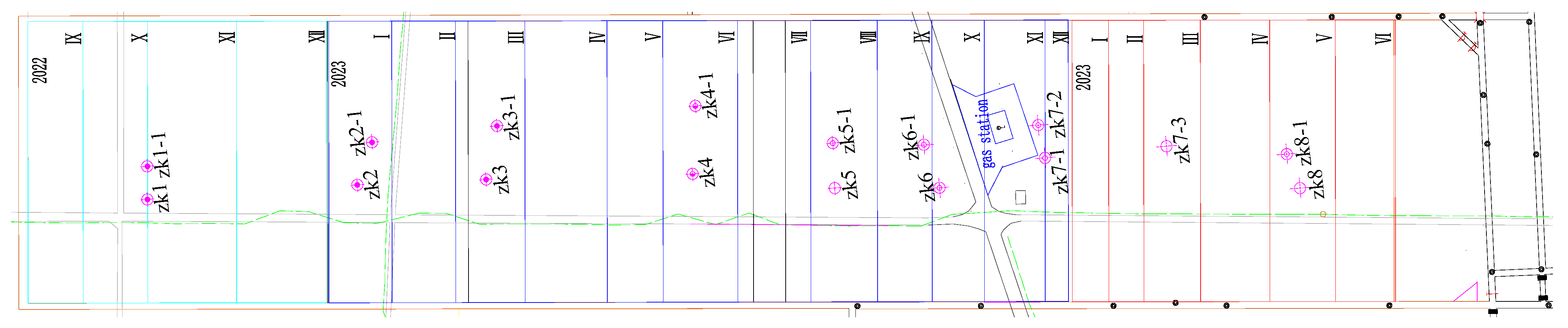
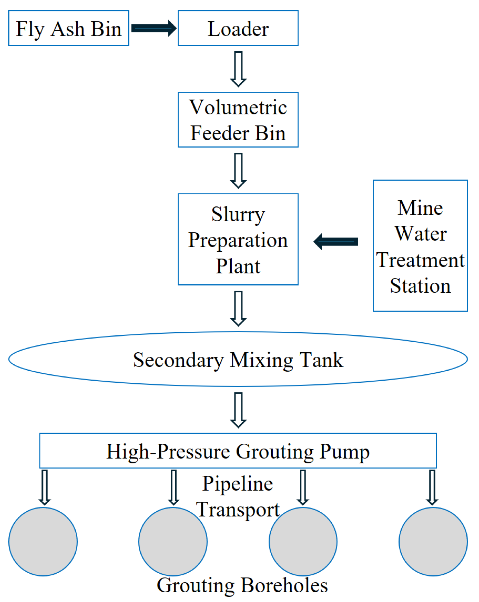
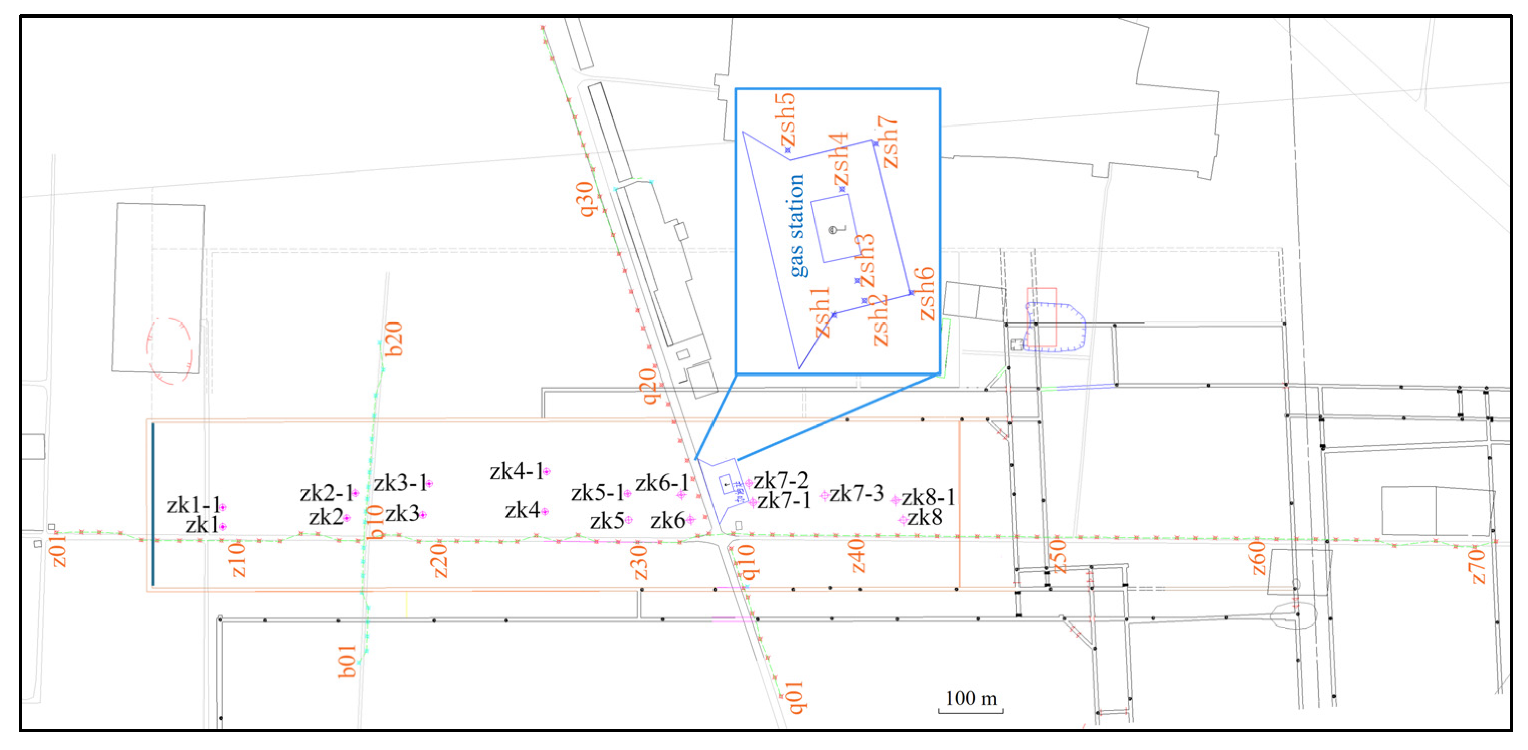
The 3801 working face commenced mining on 7 September 2022. A total of 16 grouting holes were arranged for the working face, specifically ZK1, ZK1-1, ZK2, ZK3, ZK3-1, ZK4, ZK4-1, ZK5-1, ZK6, ZK6-1, ZK7-1, ZK7-2, ZK7-3, ZK8, and ZK8-1, all of which were vertical holes. The layout of these grouting holes is illustrated in Figure 12. The designed borehole depth is 365.00 m, with a vertical distance of approximately 156 m from the coal seam, which meets the requirements for bed-separation grouting. The slurry primarily consisted of fly ash with a water-to-solid ratio of 0.7, and the grouting process is shown in Figure 13. The designed grouting pressure is 4.2 MPa. Before grouting, high-pressure water is injected into the grouting boreholes of the 3801 working face, and the variation in water pressure is continuously monitored. The timing for the initial grouting is determined based on the volume of water leakage in the boreholes; specifically, the initial grouting is initiated when a sudden increase in water leakage is observed. Grouting for a given borehole is terminated once its orifice pressure reaches the designed value. Calculated based on a daily advance of 2.4 m for the working face, combined with the designed grouting-to-mining ratio and the water-to-solid ratio of the slurry, approximately 3110 tons of fly ash should be injected daily. Bed-separation grouting began on October 30 of the same year. Mining was completed on 3 July 2024, with a cumulative advance distance of approximately 1224.3 m. Grouting operations concluded on 25 August of the same year, reaching a total grouting volume of 2.1769 million m3 and a grouting-to-mining ratio of approximately 0.68.

6.2. Surface Subsidence Control Effects of the 3801 Working Face

(1)
Layout of surface movement and deformation observation lines for the 3801 working face
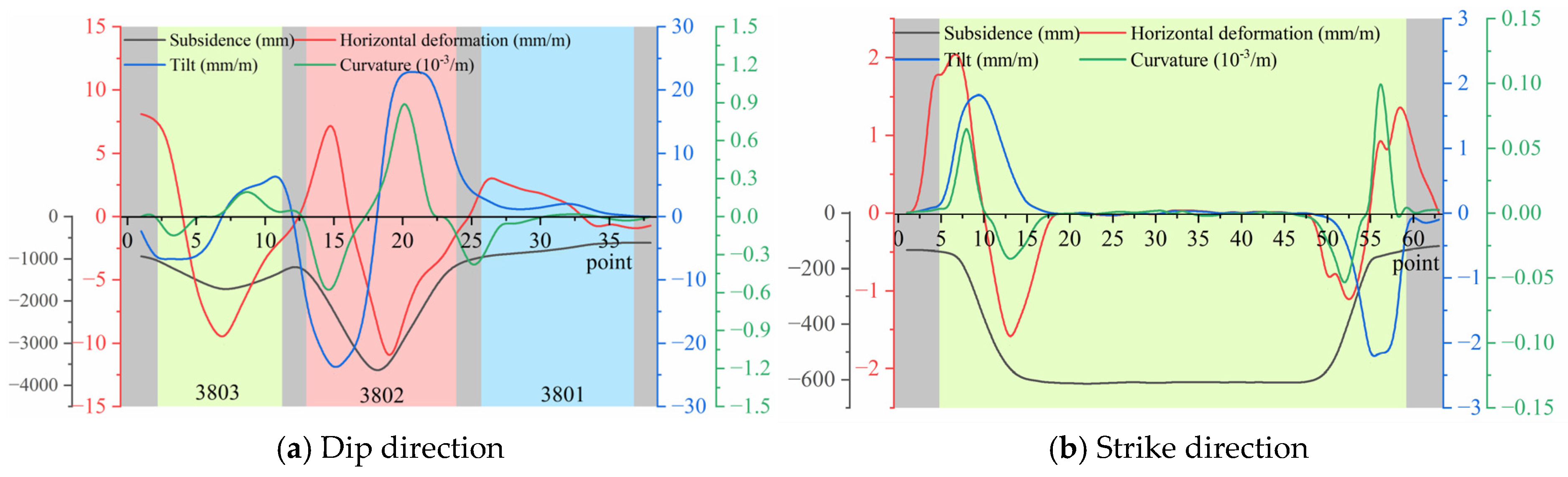
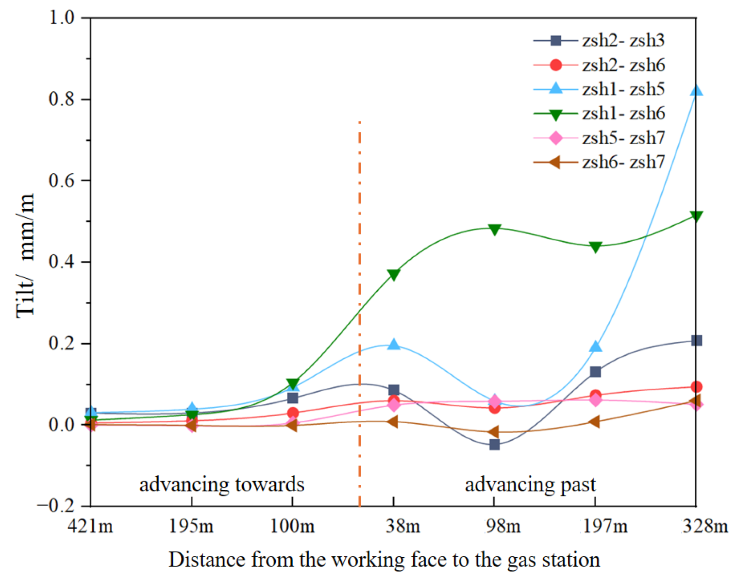
The 3801 working face is equipped with three observation lines: Line Z, Line B, and Line Q. Their layout is shown in Figure 14. Line Z is arranged along the strike direction of the working face, comprising 71 measuring points. Line B and Line Q are arranged along the dip direction, with 20 points on Line B and 39 points on Line Q. Specifically, Line Q passes through the surface gas station. The layout includes the refueling area, oil depot, office area, and warehouse. A total of seven measuring points (zsh1–zsh7) are situated within the gas station area, with points zsh2, zsh3, and zsh6 specifically located in the oil storage tank area.
Surface movement and deformation observations for Lines Z, B, and Q commenced on 11 December 2022, while monitoring for the gas station area began on 8 March 2023. As of 21 October 2024, 90 sets of cumulative data were recorded for the main survey lines, and 82 sets for the gas station points. Based on the plane coordinates and elevations, the curves for surface subsidence, inclination, curvature, and horizontal deformation were plotted. These data are used to analyze the laws of surface movement under bed-separation grouting and evaluate the resulting impact on the gas station’s stability.
(2)
Surface movement and deformation characteristics of the 3801 working face
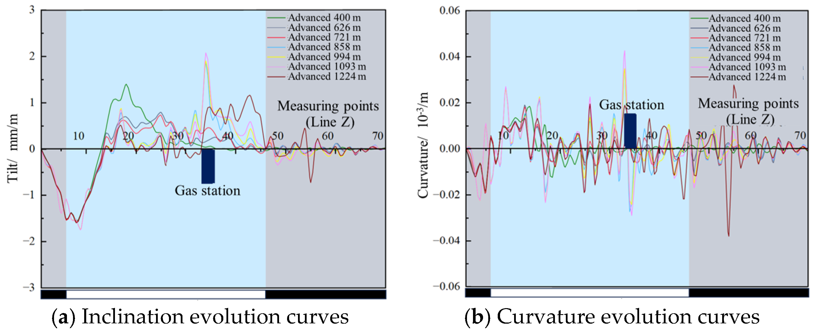
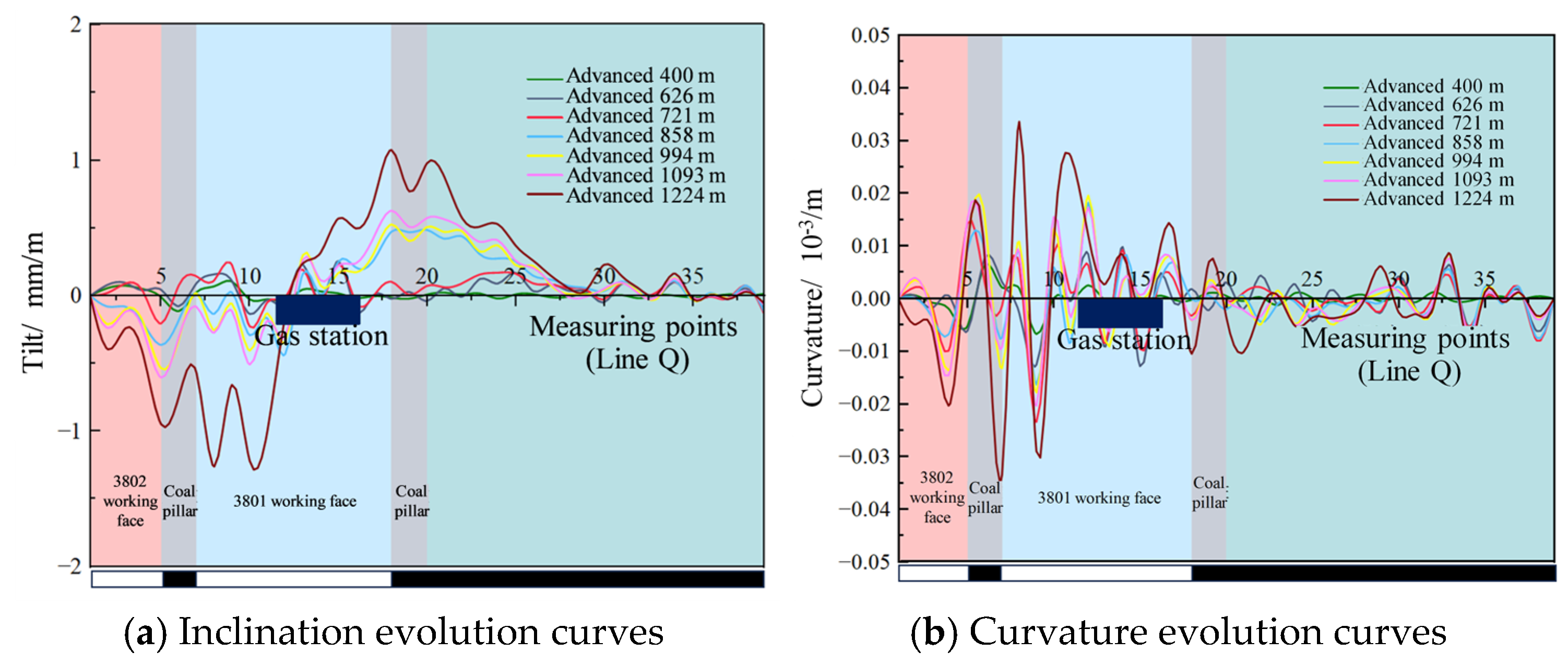
As shown in Figure 15, measuring points Z34 and Z35 are located on the west side of the gas station. The inclination between Z34 and Z35 reached a maximum of 1.15 mm/m when the working face had advanced 197 m past the gas station, later stabilizing at 0.89 mm/m. The curvature values at Z34 and Z35 reached their peaks of −0.027 mm/m2 and −0.014 mm/m2, when the working face was 38 m and 197 m beyond the gas station, respectively. After the completion of mining and surface stabilization, these values settled at 0.004 mm/m2 and−0.005 mm/m2. As shown in Figure 16, measuring points Q12–Q16 are situated on the north side of the gas station. The maximum inclination was observed between Q14 and Q15 after mining concluded, reaching 0.57 mm/m. The maximum curvature occurred at point Q12 when the working face passed directly beneath the gas station, measuring 0.018 mm/m2, and decreased to 0.013 mm/m2 after mining. All the above indices remain well within the allowable limits for surface movement and deformation protection.
As shown in Figure 17, the dip direction (between measuring points zsh2 and zsh3) and the strike direction (between measuring points zsh2 and zsh6) of the oil storage tank in the gas station reach the maximum value after the mining of the working face is completed, which are 0.208 mm/m and 0.095 mm/m, respectively. The maximum value of the remaining measuring points is also reached after the surface stability is completed, and the maximum value is located between the measuring points zsh1-zsh5, which is 0.820 mm/m. The inclination in the gas station does not exceed the allowable deformation limit requirement. The business hall is located between monitoring points zsh3 and zsh4. During and after mining of the working face, surface movement and deformation observations show that the maximum horizontal deformation in the business hall area is 1.43 mm/m, and the maximum curvature is 0.01 × 10⁻³/m.
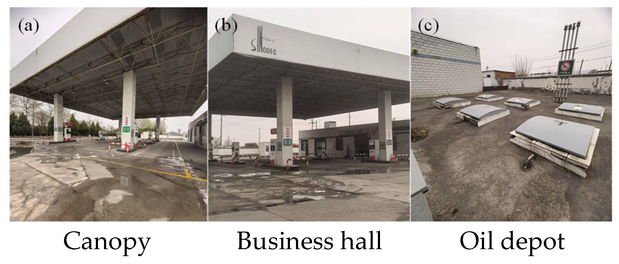
Since the surface movement and deformation monitoring of the 3801 working face began later than the mining of the 3802 and 3803 working faces, the above analysis only reflects the surface movement and deformation in the gas station area during and after the mining of the 3801 working face. To further determine the actual maximum surface movement and deformation within the gas station after the mining of the 3801 working face, the probability integral method was first adopted to predict the surface movement and deformation induced by the mining of the 3802 and 3803 working faces, thereby obtaining the surface movement and deformation in the gas station before the mining of the 3801 working face. The prediction parameters were consistent with those in Table 3, and the predicted results are shown in Figure 18. Subsequently, the predicted results were superimposed with the surface movement and deformation measured in the gas station during the mining of the 3801 working face. The calculated actual maximum tilt within the gas station is approximately 2.75 mm/m; the actual maximum horizontal deformation in the business hall area is about 3.74 mm/m, and the actual maximum curvature is about 0.08 × 10⁻³/m. Figure 19 is a field photograph of the gas station after the mining of 3801 working face. No significant deformations or cracks were observed in the building structures, such as the gas station canopy, business hall and oil depot, and the protection effect is good. The gas station has been in normal business since the mining of the working face.

7. Conclusions

(1)
Following the sequential mining of the 3802, 3803, and 3801 working faces, the No. 17 bed separation was ultimately retained above the 3801 working face. This separation zone forms an “inverted triangle” shape, situated 135 m vertically above the coal seam. Located above the water-conducting fracture zone and protected by a substantial isolation zone, it fulfills the necessary conditions for bed-separation grouting filling mining.
(2)
Physical and numerical simulations of the grouting filling mining in the 3801 working face were conducted. The results demonstrate that the underlying strata are well-compacted after grouting, significantly reducing the movement of the overlying strata and surface subsidence.
(3)
The probability integral method was employed to predict surface movement and deformation for the 3801 (bed-separation grouting filling mining), 3802 (fully mechanized top-coal caving), and 3803 (full-seam mining) working faces. All predicted indices satisfy the control requirements for the gas station. Combined with simulation results, the 3801 working face is confirmed to meet the criteria for bed-separation grouting mining.
(4)
Engineering practice at the 3801 working face confirms that the surface movement and deformation values measured during and after mining do not exceed the allowable protection limits. No significant deformations or cracks were observed in the canopy, business hall, or oil depot. The protection effect is excellent, and the gas station has maintained normal operations throughout the mining period.

Author Contributions

Conceptualization, T.H. and S.S.; Formal analysis, T.H.; Funding acquisition, X.Q. and H.M.; Methodology, D.Y. and H.M.; Visualization, N.Z.; Writing—original draft, S.S. and F.L.; Writing—review and editing, X.Q. and D.Y. All authors have read and agreed to the published version of the manuscript.

Funding

The research described in this paper was financially supported by the Key Research and Development Program of Shandong Province (2025CXPT205) and the National Natural Science Foundation of China (52404133, 52274128, 52574153).

Data Availability Statement

The original contributions presented in this study are included in the article. Further inquiries can be directed to the corresponding author. The data are not publicly available due to confidentiality restrictions related to the mine site.

Conflicts of Interest

Author Tao Han was employed by Shanxi Coal International Energy Group Co., Ltd. The remaining authors declare that the research was conducted in the absence of any commercial or financial relationships that could be construed as a potential conflict of interest.

References

  1. Wang, D.; Wang, Z.; Li, Y.; Wang, Y. Ground subsidence prediction and shaft control in pillar recovery during mine closure. Processes 2025, 13, 3274. [Google Scholar] [CrossRef]
  2. Xuan, D.; Xu, J.; Wang, B. Green mining technology of overburden isolated grout injection. J. China Coal Soc. 2022, 47, 4265–4277. [Google Scholar] [CrossRef]
  3. Ma, H. Surface subsidence control technology of multi-bed separation grouting. Coal Geol. Explor. 2021, 49, 150–157. [Google Scholar] [CrossRef]
  4. Zhang, W.; Zhang, J.; Zhang, Y.; Liu, W.; Li, L.; Nan, D.; Zhao, G.; Yang, C.; Bian, H.; Shao, H.; et al. Stress Redistribution Mechanisms and Subsidence Control of Fluidized Gangue Backfilling in Underground Coal Mining: Integrated Experimental and Numerical Investigation. Energy Sci. Eng. 2026, e70490. [Google Scholar] [CrossRef]
  5. Ding, P.; Yan, S.; Chang, L.; Li, Z.; Guo, Q.; Xu, L.; Akdag, S.; Zhou, C. Temperature-dependent mechanical properties and energy evolution of cemented tailings backfill: A triaxial testing and damage modeling study. Powder Technol. 2026, 470, 122027. [Google Scholar] [CrossRef]
  6. Yang, K.; Wei, Z.; Zhao, X.; He, X.; Zhang, J.; Ji, J. Theory and technology of green filling of solid waste in under-ground mine at coal power base of Yellow River Basin. J. China Coal Soc. 2021, 46, 925–935. [Google Scholar] [CrossRef]
  7. Guan, J. Research on surface subsidence control by overburden bed-separation grouting filling mining technology. Inn. Mong. Coal Econ. 2024, 6, 73–75. [Google Scholar] [CrossRef]
  8. Ma, H.W.; Sui, W.H.; Ni, J.M. Environmentally sustainable mining: A case study on surface subsidence control of grouting into overburden. Environ. Earth Sci. 2019, 78, 320. [Google Scholar] [CrossRef]
  9. Shen, W.; Hao, Y.; Chang, L.; Yang, J. Comprehensive evaluation of the effect of overburden bed-separation grouting filling. Inn. Mong. Coal Econ. 2022, 15, 59–61. [Google Scholar] [CrossRef]
  10. Zhang, Z. Spatio-temporal evolution laws of overburden bed-separation and grouting mining practice: A case study of the 3117 working face in Xiadian Coal Mine. Coal Geol. China 2023, 35, 33–40. [Google Scholar] [CrossRef]
  11. Wang, F. Research on safety countermeasures for hazardous chemicals storage at gas stations under high-temperature environments. China Pet. Chem. Stand. Qual. 2025, 45, 15–17. Available online: https://kns.cnki.net/kcms2/article/abstract?v=uxn9QsgV9c8L4P1QzR-M_D_Qz1LB2dlxZ5nm7RtX_3EEWaNy0zHOgRACjvdj2y9_RPVpPK5OibT9kSERe_5vSqFwkj8n5AvmcBYUDKTurErWefzhAG2M-QEUM6zCqDcgvR98jEEwTohMfODjtz9BVUUYW7lOk-nhwzNfY26VyBm4d7U50EG7ZA==&uniplatform=NZKPT&language=CHS (accessed on 20 March 2026).
  12. Han, L.; Yang, K.; Wang, T.; Pei, C.; Xu, Q.; Zou, E. Study on simulation experiment of overburden bed-separation grouting to control surface movement and deformation under buildings. Coal Technol. 2024, 43, 20–26. [Google Scholar] [CrossRef]
  13. Li, C. Study on surface subsidence reduction technology by overburden bed-separation grouting filling in Damoling Coal Mine. Mod. Chem. Res. 2025, 17, 140–142. [Google Scholar] [CrossRef]
  14. Su, Z.; Liu, L.; Zhang, C. Application of overburden bed-separation grouting filling mining technology under villages. Shandong Coal Sci. Technol. 2023, 41, 226–228. [Google Scholar] [CrossRef]
  15. Guo, W.; Wu, D.; Guo, M.; Hu, Y.; Yang, W.; Wang, B. Multi-bed separation grouting in “three-soft” thick coal seams mining and its application. Coal Sci. Technol. 2025, 53, 1–12. [Google Scholar] [CrossRef]
  16. Wang, B.; Guo, W.; Guo, M.; Yang, H.; Jia, M.; Li, D.; Wang, Z. Research on subsidence reduction technology by overburden bed-separation grouting in isolated working face mining under villages. J. China Coal Soc. 2025, 50, 87–97. [Google Scholar] [CrossRef]
  17. Xuan, D.; Xu, J. Field study of longwall fully-mechanized caving mining by overburden isolation grouting under a surface railway tunnel. J. Min. Saf. Eng. 2023, 40, 1102–1110. [Google Scholar] [CrossRef]
  18. Han, L.; Yang, K.; Wang, T.; Yu, X.; Pei, C.; Xu, Q.; He, X. “Four-zone” control model and application for surface subsidence of bed-separation grouting mining. Coal Sci. Technol. 2023, 51, 23–35. [Google Scholar] [CrossRef]
  19. Cui, Y. Research and Application of Bed-Separation Grouting Mining Technology in Zhaozhuang No. 2 Coal Mine. Ph.D. Dissertation, China University of Mining and Technology, Xuzhou, China, 2021. [Google Scholar] [CrossRef]
  20. Cheng, J. Study on the Layout of Grouting Boreholes for Overburden Bed-Separation Grouting Filling in Coal Mining Under Villages near the Stopping Line. Master’s Thesis, China University of Mining and Technology, Xuzhou, China, 2015. Available online: https://kns.cnki.net/kcms2/article/abstract?v=uxn9QsgV9c8K3iO3oa5w7Q0RJWoFAQ0eQw7-Mb3EZUPVY1FB4tkaMa_7XwJ-SBoKILSvWSYzkZnizMWP-4pzqVtNnkvZjkSqt24HVQCpjPPcseIGUD4zAiPhfl-YkssakzAVEnfvVh6oivsYfK-x1mffxrIVJiwo2TzPvE7mX4MRFytxLTTNsg==&uniplatform=NZKPT&language=CHS (accessed on 20 March 2026).
  21. Li, T. Mining practice of isolated grouting and filling under a railway tunnel in the Yangquan mining area. Saf. Coal Mines 2020, 51, 155–158. [Google Scholar] [CrossRef]
  22. Zheng, W.; Zhang, C.; Feng, X.; Liu, S. Photogrammetric Deformation Monitoring Method and Accuracy Analysis of Gas Station’s Tent. J. Geomat. 2016, 41, 45–47+52. [Google Scholar] [CrossRef]
  23. Cui, M.; Li, H.; Chen, B. Inspection and identification analysis of the canopy frame of a gas station. Anhui Archit. 2024, 31, 178–180. [Google Scholar] [CrossRef]
  24. Liu, Y. Research on Safety Risk Management of Subway Shield Tunnel Undercrossing Gas Stations during Construction: Taking Guangzhou Metro H Project as an Example. Master’s Thesis, South China University of Technology, Guangzhou, China, 2024. [Google Scholar] [CrossRef]
  25. He, B. The Shield Tunnel Passes Under Fengyuquan Gas Station Simulation Analysis of Surface Settlement. Master’s Thesis, China University of Geosciences (Beijing), Beijing, China, 2021. [Google Scholar] [CrossRef]
  26. Wang, Z.; Li, C.; Li, J.; Sun, B.; Wang, H.; Yang, D. Research on Key Technical Points for Self Monitoring Implementation of Gas Stations and Oil Storage Enterprises. Mod. Chem. Res. 2024, 76–78. [Google Scholar] [CrossRef]
  27. Chen, S.; Sheng, S.; Han, L.; Yin, D.; Wang, R.; Yang, Y. Dynamic prediction of surface movement and deformation based on machine learning for overburden bed-separation grouting filling: A case study of the 3801 working face in Huoerxinhe Coal Mine. J. China Univ. Min. Technol. 2025, 54, 1261–1275. [Google Scholar] [CrossRef]
  28. Jia, Q. Allowable deformation of storage tanks on soft soil foundations. Spec. Struct. 2002, 19, 38–41. Available online: https://kns.cnki.net/kcms2/article/abstract?v=uxn9QsgV9c-CVLenL0UeYq2Yv9aBFMDt2dDcNwryqqsar_o9TeOgHbOu60ZY8F2DgjT_oNHxuA0FNL0NnnkJZb_V-_C9CEKf-q4bS4XxfdCbMdlFovM6CxCp2fT60v214HNwhJAyR5AaRy705ZMCOP7fFUGjQkab&uniplatform=NZKPT (accessed on 20 March 2026).
  29. GB50292-2015; Standard for Appraisal of Reliability of Civil Buildings. China Architecture & Building Press: Beijing, China, 2015.
  30. Guo, W.; Ge, Z.; Ma, X.; Hu, Y.; Wang, B.; Feng, Z.; Qiu, B. Theoretical system and engineering practice of overburden bed-separation grouting for subsidence reduction. J. China Coal Soc. 2026, 1–26. [Google Scholar] [CrossRef]
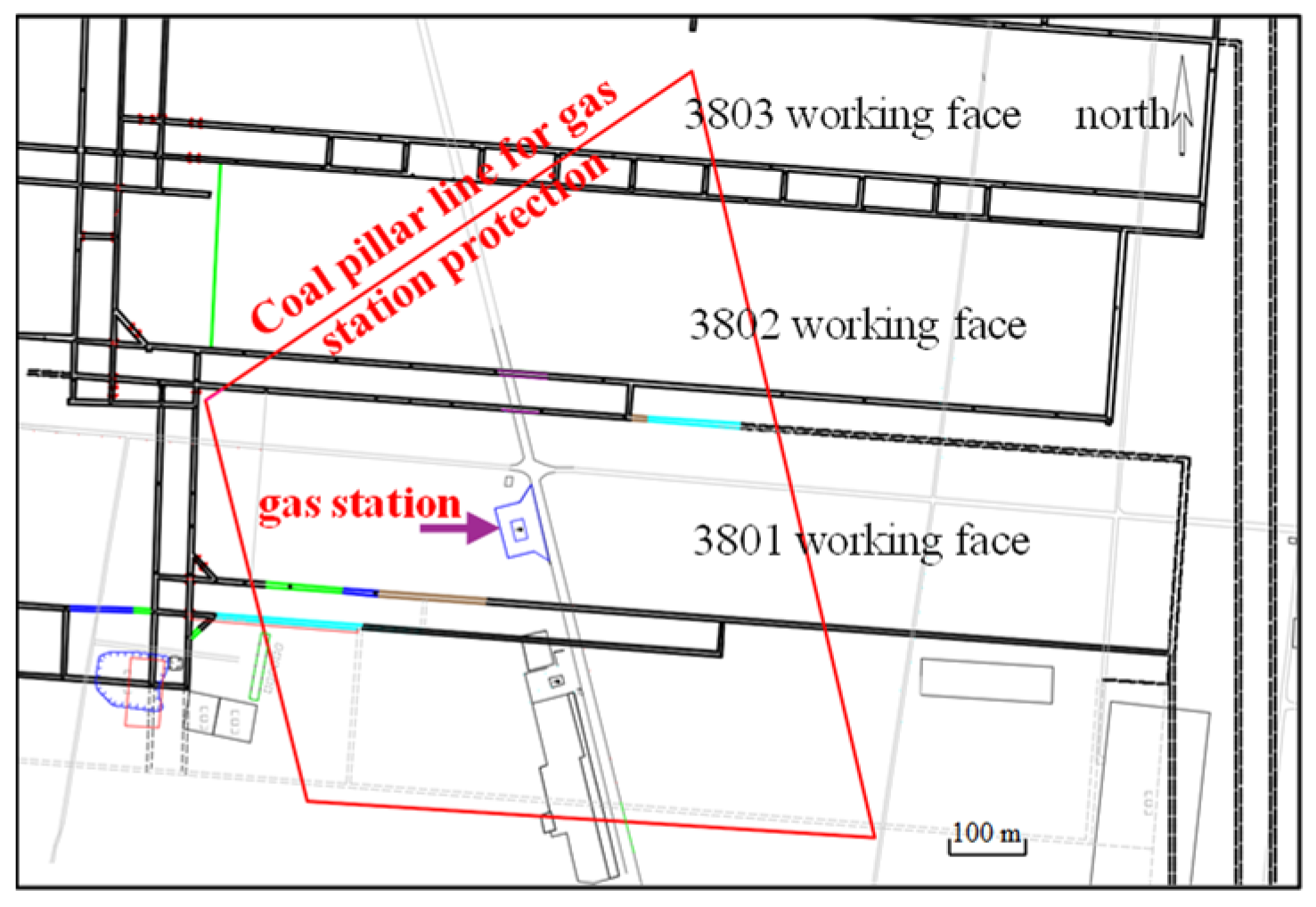
Figure 1. Surface and underground layout comparison for the 3801 working face [27].
Processes 14 01632 g001
Figure 2. Physical similarity model of 3801 working face mining.
Processes 14 01632 g002
Figure 3. Contour plots of overburden movement and vertical displacement after the mining of the 3801 working face.
Processes 14 01632 g003
Figure 4. Physical similarity simulation experimental model of the 3801 working face.
Processes 14 01632 g004
Figure 5. Contour plots of overburden movement and vertical displacement after bed-separation grouting filling mining in the 3801 working face.
Processes 14 01632 g005
Figure 6. Surface movement and deformation curves after bed-separation grouting filling mining in the 3801 working face (Physical Simulation).
Processes 14 01632 g006
Figure 7. Numerical model of bed-separation grouting filling mining in the 3801 working face.
Processes 14 01632 g007
Figure 8. Strata mesh division of the model.
Processes 14 01632 g008
Figure 9. Contour plots of overburden displacement after bed-separation grouting filling mining in the 3801 working face.
Processes 14 01632 g009
Figure 10. Surface movement and deformation curves after bed-separation grouting filling mining in the 3801 working face (Numerical Simulation).
Processes 14 01632 g010
Figure 11. Surface subsidence curves after bed-separation grouting filling mining in the 3801 working face.
Processes 14 01632 g011
Figure 12. Layout of grouting holes for the 3801 working face.
Processes 14 01632 g012
Figure 13. Process flow of fly ash grouting.
Processes 14 01632 g013
Figure 14. Surface movement and deformation observation lines for the 3801 working face.
Processes 14 01632 g014
Figure 15. Surface movement and deformation curves of the strike observation Line Z for the 3801 working face.
Processes 14 01632 g015
Figure 16. Surface movement and deformation curves of the dip observation Line Q for the 3801 working face.
Processes 14 01632 g016
Figure 17. Inclination curves of the measuring points in the gas station.
Processes 14 01632 g017
Figure 18. Surface subsidence curves after bed-separation grouting filling mining in the 3802 and 3803 working face.
Processes 14 01632 g018
Figure 19. Photographs of the surface gas station after mining of the 3801 working face.
Processes 14 01632 g019
Table 1. Lithology of boreholes in the 3801 working face area.
Serial NumberRock Layer NameThickness/mBuried Depth/mSerial NumberRock Layer NameThickness/mBuried Depth/m
1unconsolidated layer174.65174.6536mudstone5.50372.50
2siltstone2.85177.5037medium-grained sandstone9.50382.00
3medium-grained sandstone10.50188.0038sandy mudstone3.00385.00
4sandy mudstone8.00196.0039fine-grained sandstone2.50387.50
5fine-grained sandstone4.50200.5040coarse-grained sandstone9.95397.45
6siltstone6.50207.0041mudstone1.05398.50
7medium-grained sandstone4.00211.0042sandy mudstone5.00403.50
8mudstone2.00213.0043siltstone3.50407.00
9medium-grained sandstone9.00222.0044mudstone6.00413.00
10mudstone4.00226.0045sandy mudstone11.00424.00
11medium-grained sandstone3.00229.0046coarse-grained sandstone2.00426.00
12sandy mudstone12.00241.0047mudstone6.00432.00
13fine-grained sandstone3.00244.0048siltstone2.50434.50
14medium-grained sandstone4.00248.0049medium-grained sandstone10.50445.00
15sandy mudstone8.50256.5050mudstone2.00447.00
16siltstone6.10262.6051fine-grained sandstone3.00450.00
17sandy mudstone9.40272.0052coal0.30450.30
18medium-grained sandstone8.00280.0053mudstone0.70451.00
19sandy mudstone6.00286.0054sandy mudstone4.60455.60
20siltstone5.00291.0055coal0.65456.25
21medium-grained sandstone15.00306.0056mudstone1.25457.50
22mudstone2.00308.0057medium-grained sandstone4.00461.50
23medium-grained sandstone4.50312.5058fine-grained sandstone2.50464.00
24siltstone4.50317.0059mudstone3.60467.60
25sandy mudstone8.50325.5060sandy mudstone0.90468.50
26siltstone4.50330.0061sandy mudstone0.40468.90
27medium-grained sandstone3.00333.0062coal2.10471.00
28sandy mudstone7.00340.0063mudstone1.50472.50
29siltstone4.00344.0064sandy mudstone2.50475.00
30mudstone3.50347.5065fine-grained sandstone11.50486.50
31sandy mudstone2.50350.0066mudstone0.80487.30
32fine-grained sandstone6.00356.00Mcoal5.96493.26
33sandy mudstone2.00358.0068mudstone1.14494.40
34fine-grained sandstone5.50363.5069medium-grained sandstone1.60496.00
35sandy mudstone3.50367.0070sandy mudstone5.50501.50
Table 2. Parameters of the Double-Yield constitutive model for fly ash.
LithologyDensity/kg·m−3Bulk Modulus/GPaShear Modulus/GPaInternal Friction Angle/°Dilation Angle/°
Fly ash110535152510
Table 3. Main calculation parameters for surface movement and deformation prediction.
Mining Methodqtan βbθS0
Fully mechanized top-coal caving mining/full-seam mining0.862.60.3086°0.08H
Bed-separation grouting filling mining0.12.60.3086°
Note: q—subsidence coefficient; tan β—tangent of the major influence angle; b—horizontal displacement coefficient; θ—propagation angle of mining influence; S0—inflection point offset.
Disclaimer/Publisher’s Note: The statements, opinions and data contained in all publications are solely those of the individual author(s) and contributor(s) and not of MDPI and/or the editor(s). MDPI and/or the editor(s) disclaim responsibility for any injury to people or property resulting from any ideas, methods, instructions or products referred to in the content.