Abstract
Pre-extraction gas technology is commonly used in coal mines to extract gas from single coal seams, initial protective layers, and both unprotected and protected coal seams. With the development of drilling equipment, directional long drilling, pre-extraction, coal seam gas technology has been widely applied, and negative pressure extraction is one of the key factors affecting the effectiveness of directional long drilling gas extraction. In order to determine the reasonable length of directional long boreholes, studying the negative pressure distribution and time-varying rules within such boreholes is of great significance for guiding later borehole layout and gas extraction. The COMSOL Multiphysics software v.5.3. was used to couple and solve the dynamic model of temperature, stress, and seepage in coal-containing gas, as well as the mathematical model of negative pressure attenuation in directional long boreholes. The gas pressure distribution in the coal surrounding the directional long borehole and the distribution and time-varying law of negative pressure in the borehole were studied. Then, the distribution and time-varying law of negative pressure in directional long borehole extraction were tested on site. Research has shown that the negative pressure attenuation during directional long drilling has a relatively small impact on the effectiveness of coal gas extraction, while the negative pressure at the hole opening is the key factor affecting the effectiveness of gas extraction. In the early stage of extraction, as the drilling depth increases, the pressure loss inside the hole increases and the negative pressure inside the hole decreases. As the extraction time becomes longer, the pressure loss inside the borehole decreases and the negative pressure inside the borehole gradually returns to the negative pressure value at the orifice. The gas flow velocity inside the extraction borehole gradually increases from the bottom of the hole to the hole opening, and the flow velocity at the bottom of the hole remains basically constant. The gas flow velocity inside the hole gradually decreases with the extension of extraction time, and the smaller the distance from the extraction hole opening, the greater the flow attenuation. The collapse of drilling holes during extraction affects the attenuation of negative pressure inside the hole in the short term. As the extraction time increases, the impact of the collapse on the negative pressure inside the hole is limited. The temperature of coal can significantly affect the negative pressure and gas flow distribution inside the pores. Considering the temperature effect, the gas flow velocity inside the pores is higher and the pressure loss is lower in the short term. On-site tests have determined that the depth of ultra-long directional drilling holes is shallower than 327 m, and the negative pressure changes inside the borehole are not significantly different from the negative pressure at the hole opening. The negative pressure stabilization speed near the hole opening and bottom is fast, usually reaching its peak within 3–10 min. The negative pressure stabilization process from the borehole opening to the hole bottom shows a “fast slow fast” trend. When using double-sided extraction, the time for negative pressure to reach stability is significantly shortened compared to single-sided extraction, and double-sided extraction is beneficial for improving the effectiveness of coalbed methane extraction.
1. Introduction
Gas, also known as coalbed methane (CBM), is a clean energy source [1,2]. China is rich in CBM resources, with the total amount of gas resources within a depth of 2000 m reaching 36.8 × 10¹² m3, accounting for approximately 13% of the world’s total CBM resources [3]. Currently, gas extraction in China still primarily relies on underground extraction methods, which result in low extraction concentrations and high utilization costs. The extracted gas is mainly emitted into the atmosphere. Methane, the main component of gas, is the second most significant greenhouse gas. Compared to carbon dioxide, methane has a shorter atmospheric lifetime but a stronger greenhouse effect [4]. According to the assessment report released by the Intergovernmental Panel on Climate Change (IPCC) in 2021, over the past two decades, the global warming potential of methane has been 80.5 to 82.5 times higher than that of carbon dioxide. Therefore, there is an urgent need to enhance the development and utilization of coal mine gas. Improving the extraction concentration and flow rate of gas has become a key focus and hot topic in the research and development of coal mine gas utilization. In underground coal mines, pre-drainage technology for regional coal seam gas is mainly employed for single coal seams, the first-mined protective seams, and both unprotected and protected seams [5]. With the advancement of drilling equipment, the application of kilometer-long directional borehole gas extraction technology in regional gas extraction has been promoted and has achieved remarkable results [6,7]. The use of kilometer-long directional long boreholes effectively expands the gas extraction range, prolongs the extraction duration, and provides advanced technical support for achieving a balance between “drainage, excavation, and mining” in high-gas and outburst-prone mines. Gas-bearing coal is a dual-porosity system composed of matrix and fractures [8]. Coal seam gas undergoes processes such as desorption, diffusion, and seepage within the coal mass, eventually flowing into gas extraction boreholes under the influence of extraction negative pressure [9,10]. Variations in the extraction negative pressure within directional boreholes directly affect the velocity of gas flow from the coal mass into the extraction boreholes and, consequently, the extraction efficiency. Investigating the distribution and temporal variation in extraction negative pressure within long directional boreholes is of profound significance for enhancing the effectiveness of gas extraction in such boreholes.
Scholars in China have conducted in-depth research on the variations in negative pressure during gas extraction in ordinary bedding boreholes. Tao et al. [11] conducted field tests on the negative pressure loss in extraction boreholes and found that the negative pressure loss did not change significantly in a short period. However, over a long duration of extraction, the negative pressure loss within the borehole increased due to borehole wall deformation. Using the hydrodynamic friction resistance formula, Smirnova [12,13] calculated the negative pressure loss in boreholes and found that, compared to the negative pressure at the borehole opening, the negative pressure loss within the borehole was relatively small. Wang et al. [14] established a gas flow model within bedding boreholes and calculated and investigated on site the attenuation of negative pressure during gas extraction in a 100 m deep bedding borehole. Zhang et al. [15,16] discovered that the instability and collapse of extraction boreholes had a significant impact on the distribution of negative pressure during extraction. Collapse could alter the distribution of negative pressure, thereby affecting extraction parameters. They proposed a detection technique for identifying borehole instability and collapse by testing the distribution of negative pressure during extraction. Liu et al. [17] and Cheng et al. [18] found that the negative pressure within boreholes during gas extraction followed an exponential function relationship with borehole depth, pointing out that a reasonable range of negative pressure within the borehole was necessary to ensure the effectiveness of gas extraction. Zhang et al. [19] studied the influence of gas extraction boreholes on the variation in gas pressure in coal and rock masses through similarity simulation.
Regarding the research on negative pressure within directional long boreholes, early studies primarily focused on oil extraction [20,21,22,23,24]. In recent years, with the application of directional long borehole extraction technology in the development and utilization of coalbed methane, an increasing number of scholars have begun to investigate the variations in negative pressure during gas extraction within these boreholes. Liu et al. [25,26] conducted similar simulation experiments in the laboratory to study the changes in negative pressure during directional long borehole extraction. He found that the extraction negative pressure gradually decreased along the length of the borehole and followed a negative exponential relationship with the borehole length. The gas flow rate in the extraction borehole gradually decreased along the length of the borehole, and the two followed a negative exponential relationship. Du et al. [27] discovered a positive linear correlation between the negative pressure at the borehole opening and that within the directional long borehole. As the borehole depth increased, both the negative pressure loss during extraction and the negative pressure loss per hundred meters increased. Xu et al. [28] found that the negative pressure during gas extraction within directional long boreholes was positively correlated with the initial gas pressure of the extracted coal seam, coal thickness, permeability, diffusion coefficient, and borehole spacing. Qi et al. [29] studied the exponential relationship between the negative pressure in long boreholes and borehole depth, noting that the greater the extraction negative pressure, the larger the attenuation of extraction negative pressure. For kilometer-long directional boreholes, the pure gas volume within 300 m decreased significantly over time, while the decrease in pure gas extraction volume beyond 300 m was relatively smaller with increasing time.
Scholars’ research on negative pressure during gas extraction in directional boreholes has primarily focused on theoretical analysis, similar experiments, and numerical analysis. Some scholars have also conducted on-site investigations of the negative pressure during gas extraction in boreholes. However, due to limitations in experimental equipment, on-site investigations of negative pressure have mainly been concentrated within borehole depths of 200 m. Reports on negative pressure testing in directional boreholes beyond 200 m in depth have not yet been found. Additionally, in the development of mathematical models for coal seam gas flow and coupled mathematical models for extraction negative pressure, the coupling of stress, seepage, adsorption/desorption migration, and negative pressure during extraction within the borehole has been mainly considered. Several previous studies [30,31,32] have indicated that the temperature field within coal masses significantly affects gas migration. Therefore, this study has established a coupled dynamic model for seepage, stress, and temperature in gas-bearing coal masses, along with a mathematical model for the negative pressure distribution in extraction boreholes. Numerical simulations have been conducted on gas extraction from coal seams using directional long boreholes to analyze the distribution and temporal variation of in negative pressure during extraction within these boreholes. We have also compared on-site measured flow rate data with simulation results and conducted on-site measurements of the distribution and temporal variations in negative pressure in directional long boreholes. This research aims to provide guidance for determining the key parameters of directional long boreholes in the same coal seam and for the development of directional long borehole extraction technology.
2. Theoretical Model for Gas Migration in Coal Seams
The assumptions regarding gas migration in coal seams are as follows: (1) The gas-bearing coal is assumed to be a homogeneous and isotropic medium, consisting of pore and fracture structures. (2) The coal mass is saturated with single-phase gas. (3) The seepage of gas within fractures conforms to Darcy’s law, while the diffusion within pores follows Fick’s diffusion law. (4) The gas is treated as an ideal gas. (5) The temperature of the coal mass is not constant, and the influence of temperature on seepage, adsorption, and desorption processes is considered. (6) Adsorption/desorption and variations in gas pressure induce equal strains in all three directions of the coal mass.
2.1. Stress Field Equations for Gas-Bearing Coal and Rock
Based on the principle of effective stress in porous media, the stress equation for coal and rock masses, which accounts for coal adsorption-induced swelling and temperature deformation, is expressed as follows [33,34].
where G represents the shear modulus, G = E/(2·(1 + ν)); v represents Poisson’s ratio; δij is the Kronecker delta; α = 1 − K/Ks; K is the bulk modulus of coal, MPa, K = E/(3·(1 − 2ν); E represents the elastic modulus of the coal seam, MPa; Ks denotes the bulk modulus of the coal matrix, MPa; p stands for the gas pressure, MPa; fi is the volumetric stress tensor; εij refers to the components of the strain tensor; εs signifies the adsorption-induced swelling strain per unit volume of coal; and T indicates the temperature of the coal mass, K.
2.2. Equation of Gas Seepage Field in Coal Seam
The gas flow equation is composed of the continuity equation, the equation of motion, the equation of state, and the gas content equation.
(1) Continuity equation
In a dual-porosity medium consisting of pores and fractures, the diffusion and desorption processes in the pore system are regarded as the mass source replenishing the fracture system. The continuity equation for gas flow is as follows:
where Ca is the mass concentration of adsorbed gas contained in the coal seam per unit volume, kg/m3; ρg is the density of gas at pressure p, kg/m3; Jc is the diffusion flux of gas passing through a unit area, kg/(s·m2); and ϕ is the porosity of the coal body, %.
(2) Flow equation
The flow of gas within the fractures of the coal body conforms to Darcy’s law [35].
where V is the seepage velocity of gas, m/s; k is the permeability of the coal seam, m2; and μ is the dynamic viscosity of gas, Pa·s.
The diffusion of gas in the pores of coal conforms to Fick’s diffusion law [36].
where D is the diffusion coefficient, m2/s.
(3) State equation
The gas state equation is as follows:
where Mg is the molecular weight of the gas, kg/(k·mol); R is the universal gas constant, R = 8.3143 J/(mol·K); and Z is the compressibility factor.
(4) Gas content equation
Gas consists of free gas and adsorbed gas, and its content equation is shown as follows [37]:
where .
Cf is the free gas content per unit volume of coal, kg/m3; ρn is the gas density under standard atmospheric pressure, kg/m3; A represents the ash content, %; W denotes the moisture content, %; a is the ultimate adsorption capacity of the coal body, m3/kg; b is the Langmuir pressure constant for coal, MPa−1; and ρc is the apparent density of the coal body, kg/m3.
The relationship between the adsorption constant of coalbed methane and temperature is as follows [38].
In Formula (7), a1, a2, a3, and b1, b2 are data determined through gas adsorption experiments, and the gas adsorption constant is a function of temperature.
By substituting Equations (3), (4), (6), and (7) into Equation (2), we can obtain Equation (8).
2.3. Dynamic Model of Porosity and Permeability
Taking into account the changes in gas pressure, temperature, and the volume deformation of the coal skeleton caused by the adsorption/desorption of gas by coal particles, the porosity of gas-containing coal rock in the elastic stage is calculated using the following formula [39,40,41,42].
where εV is the volumetric strain of coal; ϕ0 is the initial porosity; %. β is the thermal expansion coefficient of coal, 1/K; ΔT is the absolute temperature change, ΔT = T − T0; T0 is the initial temperature of the coal body, K; Δp is the change in gas pressure, MPa, Δp = p − P0; P0 is the original coal seam gas pressure, MPa; and εs is the adsorption expansion strain.
The relationship between adsorption strain s and gas pressure and temperature is shown as follows [43].
where Vm is the molar volume of gas, Vm = 22.4 × 10⁻³ m3/mol.
Permeability equation [43].
By taking the derivative of Equation (9) and substituting it into Equation (8), the gas dynamics Equation (12) can be obtained.
2.4. Temperature Field Equation
In gas-containing coal, solid coal and fluid gas are included. Ignoring the effects of temperature, pressure, and stress on the density of the coal skeleton, the total energy equation of gas-containing coal is obtained [30,31].
where λs, Cs and ρc are the thermal conductivity, specific heat, and density of the coal skeleton, respectively; qm is the energy generated per unit volume of skeleton per unit time; λg, Cg, and ρg are the thermal conductivity, specific heat, and density of gas, respectively; qg is the energy generated per unit volume of gas per unit time; and (V▽)T is the convective term, representing the temperature change caused by the movement of fluid particles.
A coupled dynamic model of seepage, stress, and temperature in gas-containing coal is composed of Equations (1) and (9)–(13). Given the corresponding boundary conditions and initial values, the gas flow law in gas-containing coal can be solved considering the influence of temperature.
3. Mathematical Model of Pressure Loss in Directional Drilling Holes
The pressure difference formed between the gas pressure in coal containing gas and the pressure inside the borehole is the power source for gas to flow into the extraction borehole in the coal body. The gas in the extraction borehole is extracted under the negative pressure of the orifice, and the geometric model of gas flow and pressure distribution inside the borehole can be established as shown in Figure 1. Due to the low density of coal seam gas, which is 0.717 kg/m3, the influence of gravity was ignored.
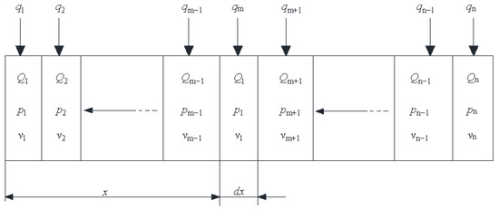
Figure 1.
Schematic diagram of a micro-element along the length of a borehole.
As shown in Figure 1, the directional long borehole is divided into n micro units along the depth direction. For the micro unit segment with a length of dx (horizontal direction) and a specific distance x from the borehole orifice, the total gas flow rate Qm, pressure pm, flow velocity vm, and gas flow rate qm flowing into the micro unit from the borehole wall, as well as the flow rate Qm+1, borehole pressure pm+1, gas flow velocity vm+1, and borehole wall flow rate qm+1 of the adjacent micro unit with a length of dx on the right side, the pressure loss inside the borehole is shown as follows [25].
where hm is the resistance loss at a distance of x from the borehole, Pa; fi is the resistance coefficient along the extraction borehole; ρ is the gas density inside the extraction borehole, kg/m3; Q(x) is the gas extraction flow rate inside the borehole at a distance of x from the borehole opening, m3/min; q(x) is the gas flow rate that flows into the interior of the borehole from the borehole wall to the micro element segment, m3/min; d is the diameter of the gas extraction borehole, m; d’ is the equivalent diameter after deformation of the gas extraction borehole, m; and ξ is the local resistance coefficient.
When calculating the drilling pressure loss, the resistance loss coefficient fi along the way is calculated as follows [21].
When Re ≤ 2320,
When Re ≥ 4000,
When 2320 < Re < 4000, the resistance coefficient generated by gas flow in the extraction borehole can be obtained by linear interpolation between Equations (15) and (16), where ε is the roughness of the pipe wall, m; Re is the Reynolds number, Re = ρvL/μ; v is the gas flow velocity inside the hole, m/s; L is the characteristic length of the fluid, m; μ is the dynamic viscosity of gas, Pa·s; and ρ is the gas density inside the hole, kg/m3.
The cumulative loss of pumping pressure from the borehole opening to a distance of x and a length of dx from the borehole can be expressed as follows.
The gas flow from the coal body into the borehole is expressed as follows:
where l is the circumference of the borehole, m.
The gas flow rate at the orifice is as follows.
By coupling the mathematical model of pressure attenuation in directional drilling holes with the models of coal seepage, stress, and temperature, it is possible to study the gas flow rate, negative pressure, and the distribution of coal gas pressure around the hole under the action of negative pressure in the extraction drilling hole.
4. Numerical Simulation Study on Negative Pressure Distribution Along Directional Long Drilling
4.1. Model and Definite Solution Conditions
A mine in Shanxi Province commonly uses kilometer-long directional boreholes for pre-extraction of coal seam gas, with the main coal seam denoted as No. 8, with a dip angle of 4–9°. The coal seam is located above the S3 sandstone at the bottom of the Shanxi Formation (P1S), with a thickness range of 2.15–10.39 m and an average thickness of 6.6 m. The maximum measured gas pressure in the coal seam is 1.72 MPa, and the permeability coefficient of the coal seam is 0.63–8.25 m2/(MPa2·d), with an average of 2.52 m2/(MPa2·d). In order to study the negative pressure distribution and time-varying law of directional long borehole gas extraction in the mine, a numerical analysis geometric model for borehole gas extraction was established with reference to [26,27], as shown in Figure 2. Other coal seam physical parameters are shown in Table 1.
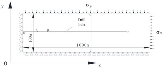
Figure 2.
Numerical simulation of the geometric model.

Table 1.
Physical property parameters of gas-bearing coal seam in a mine.
Coal contains gas in both free and adsorbed states. The free gas in coal seams exists under a certain pressure. Under the action of extraction negative pressure, the free gas in coal seams flows through the pores and fractures within the coal body into the extraction borehole. As gas extraction progresses, the gas pressure in the coal seam around the borehole gradually decreases, and the amount of free gas within the coal body reduces. Consequently, the gas flow rate entering the borehole decreases.
The flow velocity is mainly affected by the permeability of the coal seam and the gas pressure within it. While the geometry of the borehole has a certain short-term impact, its long-term influence is relatively insignificant.
The length of the model in the x-direction is 1000 m, and the width of the model in y is 100 m, representing the width of the coal seam. EF represents directional drilling, with a length of 800 m. Within the research domain, the initial and boundary conditions of the model are as follows: (1) The displacement is limited on the left and lower sides of the model, and the stress boundaries are on the right and upper sides. (2) t = 0, p1 = P0, T1 = T0 in the coal body. We extract drilling holes with t = 0, p2 = Pn, T2 = T20. (3) The upper part and both sides of the model are non flowing boundaries. The boundary of coal flowing into the borehole is the velocity boundary −k▽p1/μ, the boundary of point E at the extraction hole is the extraction pressure p2 = Pn − pf, and the boundary of point F at the end of the extraction borehole is the velocity boundary.
4.2. Analysis of the Variation Law of Coalbed Methane Pressure and Pore Pressure
The change in coal seam gas pressure can intuitively reflect the gas extraction effect. The evolution of gas pressure distribution in coal after directional long borehole extraction is shown in Figure 3.
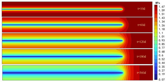
Figure 3.
Variation in gas pressure around borehole.
Figure 3 shows that under the negative pressure of extraction, the coal seam gas pressure forms an elliptical relief zone around the borehole, and the range of the relief zone increases with the increase in extraction time. Figure 4b shows the variation in gas pressure along a straight line composed of two points (0, 55) and (1000, 55) over time. Due to the variation in negative pressure inside the hole in the direction of hole depth, the negative pressure for extraction varies at different depths. However, at the same time, the gas pressure on the line is basically the same, indicating that the variation in negative pressure inside the hole has a small impact on the variation in gas pressure around the hole, and the impact of extraction negative pressure can be basically ignored. The variation in negative pressure during directional drilling along the depth of the hole is shown in Figure 4.
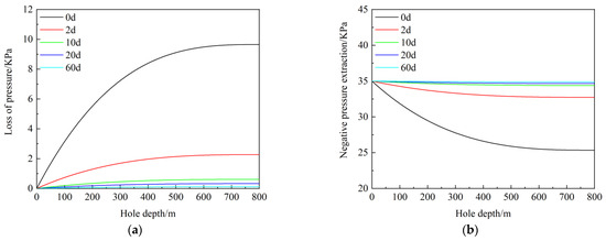
Figure 4.
Distribution of negative pressure along the hole depth. (a) Distribution of pressure loss inside the hole. (b) Distribution diagram of negative pressure inside the hole.
Figure 4 indicates that as the depth of the borehole increases, the pressure loss within the borehole also increases, but the rate of increase decreases, corresponding to a progressively smaller attenuation of negative pressure.
During the initial stage of gas drainage, there is a significant negative pressure loss within the borehole over the range of 0–300 m. The negative pressure for gas drainage attenuates from 35 kPa at the borehole opening to 27.7 kPa, representing a decrease of 20.85%. The negative pressure for gas drainage decreases by approximately 2.43 kPa per hundred meters within this range.
Within the range of 300~800 m in the borehole, the loss of negative pressure for gas drainage tends to level off. At 800 m, the negative pressure for gas drainage is 25.34 kPa, which is 9.66 kPa lower than that at the borehole opening. The negative pressure loss per hundred meters within the 300~800 m range is 0.47 kPa, which is approximately one-fifth of the negative pressure loss within the 0~300 m section of the borehole.
As the gas drainage time increases, the pressure loss within the borehole decreases. The negative pressure for gas drainage within the borehole gradually approaches the negative pressure at the borehole opening as the drainage time extends. The changes in negative pressure for gas drainage at different distances within the borehole over time are illustrated in Figure 5.
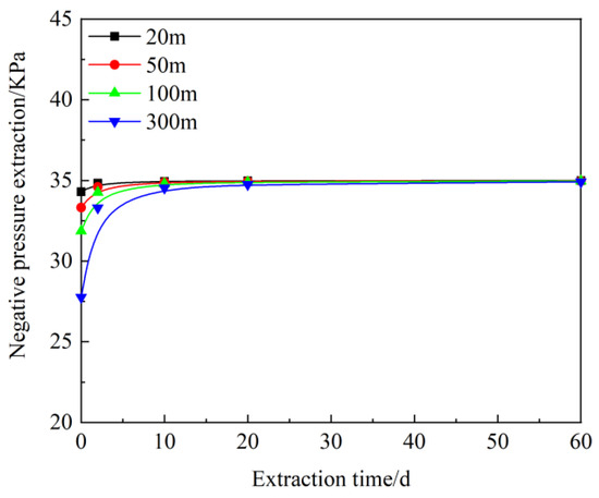
Figure 5.
Changes in the negative pressure of extraction at different locations within the borehole.
Figure 5 shows that the farther the distance from the borehole opening, the longer the time required for the negative pressure of gas drainage to recover to the initial pressure. This indicates that for long-term pre-drainage, the negative pressure of gas drainage is not the decisive factor restricting the borehole depth. Under feasible conditions, long-distance boreholes should be constructed as much as possible. After the gas in the coal mass with pores and fissures enters the gas drainage borehole through the borehole wall, under the action of negative pressure in the pipeline, the gas flows out from the borehole. The distribution of gas flow velocity within the gas drainage borehole is shown in Figure 6.
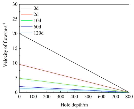
Figure 6.
Distribution of gas velocity in the extraction hole.
Figure 6 indicates that the gas flow velocity within the gas drainage borehole gradually increases from the bottom to the opening of the borehole, with the gas flow velocity at the bottom basically maintained at 0.17 m/s.
The gas flow velocity within the borehole gradually decreases with an increase in the gas drainage time. The closer the distance to the borehole opening, the greater the attenuation of the flow velocity. The gradient of change in the gas drainage flow velocity gradually decreases over time, and eventually, the flow velocities within the borehole tend to be consistent.
Field statistics on the gas drainage flow rate data from a 796 m directional long borehole in this mine show a comparison between the measured data and the numerical simulation results, as illustrated in Figure 7.
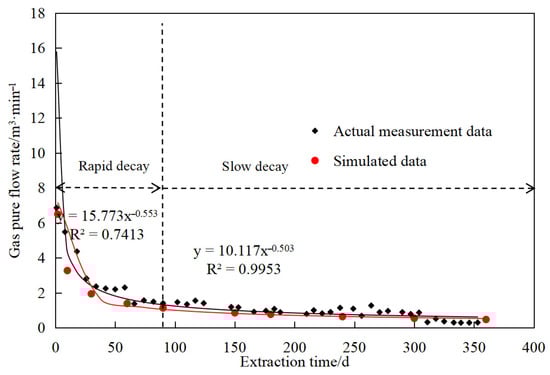
Figure 7.
Changes in orifice pumping flow.
Figure 7 illustrates that, whether based on actual measurements or numerical simulations, the gas drainage flow rate exhibits a pattern of rapid initial decay followed by a slower decay, with the gas drainage flow rate of the borehole showing a power-function relationship with time (root mean square error (RMSE) = 0.78, mean absolute error (MAE) = 0.51). During the first 0 to 80 days of drainage, the gas drainage flow rate drops sharply. After 80 days, the gas drainage flow rate tends to level off. This confirms the reasonableness of the flow velocity change pattern depicted in Figure 7.
4.3. The Impact of Changes in Drilling Aperture on Negative Pressure Inside the Hole
In order to analyze the changes in negative pressure during directional drilling after borehole collapse, the geometric model in Figure 2 was used to describe the AB section borehole collapse in Figure 2. The effective area of the borehole after collapse was 75% of the original borehole, while the other initial and boundary conditions remained unchanged. The changes in negative pressure during borehole collapse are shown in Figure 8.
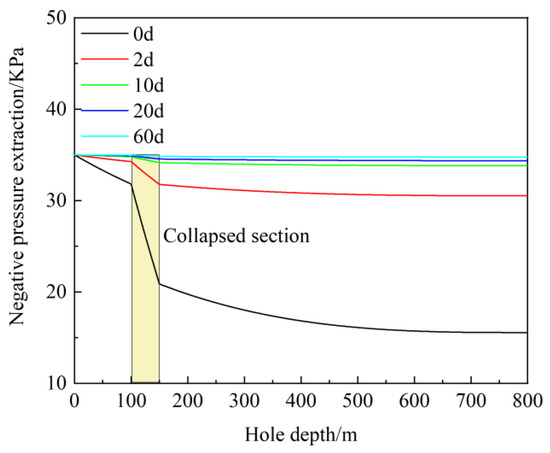
Figure 8.
Distribution of negative pressure in the borehole during hole collapse.
Figure 8 shows that, during the initial stage of gas drainage, borehole collapse exacerbates the attenuation of negative pressure for gas drainage. In the 100~150 m section of the collapsed borehole, the negative pressure for gas drainage decreases from 31.81 kPa at 100 m to 20.87 kPa at 150 m. The reduction in negative pressure for gas drainage per hundred meters of the borehole reaches 21.88 kPa, which is nine times the negative pressure attenuation when the borehole is intact. Correspondingly, within the 0–300 m section of the borehole, the negative pressure for gas drainage decreases from 35 kPa to 18.01 kPa, with a negative pressure attenuation per hundred meters of 5.66 kPa in this interval, which is 2.3 times that when the borehole is intact.
As the gas drainage time extends, the negative pressure loss within the borehole gradually decreases, and the negative pressure for gas drainage gradually recovers. After 20 days of gas drainage, the negative pressure for gas drainage in the collapsed section and on both sides maintains a value basically consistent with that at the borehole opening. However, the time required for the negative pressure for gas drainage in the collapsed borehole to recover to a stable state is longer than that for an intact borehole. Therefore, it is evident that borehole collapse can significantly alter the negative pressure distribution within the borehole, especially during the initial stage of gas drainage.
4.4. The Influence of Coal Temperature on Negative Pressure Inside the Pores
This paper compares the flow velocity and pressure loss inside the hole considering temperature, as shown in Figure 9.
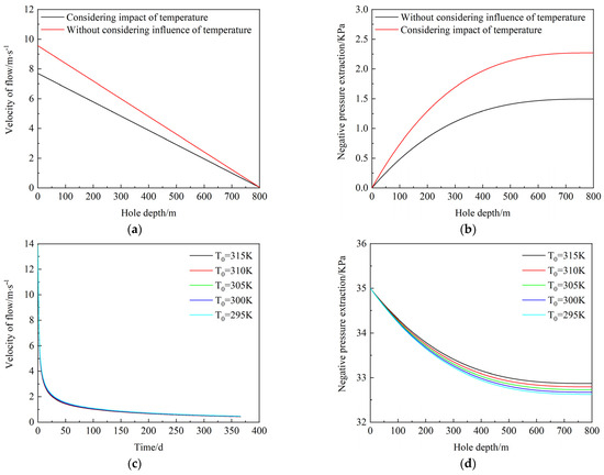
Figure 9.
Effect of temperature. (a) The influence of the model on the flow velocity inside the hole. (b) The effect of the model on negative pressure loss in hole extraction. (c) The influence of temperature on the flow velocity inside the hole. (d) The effect of temperature on negative pressure loss in hole extraction.
Figure 9 indicates that the gas flow rate inside the hole without considering the influence of coal temperature is greater than the pressure loss inside the hole without considering the influence of temperature, indicating that coal temperature is also one of the factors directly affecting the negative pressure distribution inside the hole.
Considering that the initial temperatures of the coal body are 315, 310, 305, 300, and 295 K, and that the negative pressure of the extraction in the borehole changes, this study found that the higher the initial temperature of the coal body, the greater the attenuation of the negative pressure recovery in the borehole. The initial temperature of the coal body affects the gas extraction flow rate at the borehole, and the higher the temperature, the greater the attenuation of the extraction flow rate, indicating that temperature affects the effectiveness of coal seam gas extraction.
5. Directional Long Borehole Negative Pressure Fixed-Point Testing Technology and Application Along the Borehole
To further verify the correctness of the numerical simulation, the numerical simulation results and the on-site measurements of orifice flow rates were compared.
5.1. Equipment and Technology for Negative Pressure Testing Along the Long Borehole
The directional long drilling hole negative pressure fixed-point measuring device includes five main parts: a pressure-measuring screen tube, pressure-measuring tube, pressure-measuring joint, YZC5 gas extraction parameter measurement instrument, and sealing joint, as shown in Figure 10.
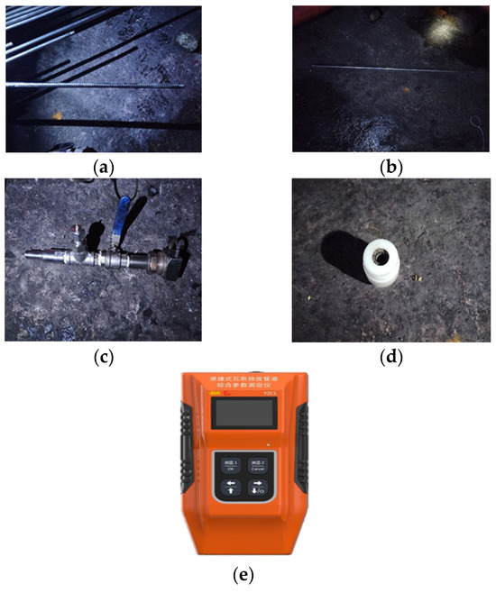
Figure 10.
Fixed-point measurement device for negative pressure inside the borehole. (a) Pressure-measuring sieve tube; (b) pressure-measuring tube; (c) pressure-measuring joint; (d) sealing joint; (e) YZC5 gas extraction parameter measurement instrument.
The pressure-measuring sieve tube is a DN15 hollow steel pipe with a length of 1.5 m. A circular hole with a diameter of 6 mm is machined within the 1.0 m length, and a 10-mesh steel wire mesh is installed inside the hole to prevent impurities such as coal slag from entering the tube. The pressure-measuring tube is a DN15 hollow steel pipe with a length of 1.5 m. The pressure-measuring tubes are connected by threads, and two dedicated sealing rubber rings are installed at the external threaded end of each pressure-measuring tube to prevent air leakage. The YZC5 instrument for gas extraction parameter measurements can measure the pressure, flow rate, carbon monoxide concentration, methane concentration and other parameters of gas extraction pipelines. The performance is shown in Table 2. The connected measuring device is shown in Figure 11.
Table 2.
Performance of gas extraction parameter measurement instrument.
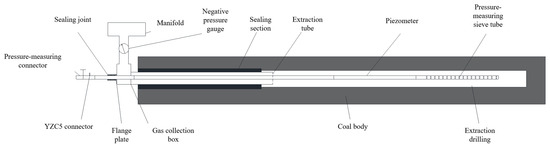
Figure 11.
Diagram showing connected measurement device.
The main steps of the on-site test are as follows: (1) Remove the flange at one end of the gas collection box and replace it with a variable diameter connector with an external thread. Connect one end of the external thread to one end of the ball valve. Then, install a sealing joint on the other end of the ball valve, and lower the pressure-measuring tube into the borehole at the end. (2) Connect one end of the pressure-measuring joint to the end of the pressure-measuring tube and the other end to the YZC5 gas extraction parameter measurement instrument. After stabilizing for 20–30 min, negative pressure measurements can be carried out. (3) Turn on the YZC5 measuring instrument and test the suction negative pressure at the position where the pressure measuring tube is lowered. Then, record and store the relevant data. (4) By withdrawing a certain number of pressure-measuring tubes to control the measurement position inside the hole, and then connecting the pressure-measuring connector, repeat steps (2) and (3) to measure the negative pressure of the extraction at different positions inside the hole. (5) After the measurement is completed, pull out the pressure measuring tube from the borehole, close the ball valve, and restore the normal pumping state.
5.2. On-Site Testing and Analysis of Negative Pressure Distribution Along a Directional Long Borehole
Numerical studies have shown that the negative pressure extracted from directional drilling along the depth of a hole is a dynamic recovery process over time. To further verify the changes in negative pressure during the extraction process, a negative pressure measurement test was conducted at drilling site 3353 in the total return 27 roadway of the five-panel area of the mine. The drilling site has one extraction borehole with a total length of 3353 m, which started extraction in September 2019. As of November 2023, the borehole has been operating normally for more than 2 years. According to numerical simulation results, during the extraction process, there is not much difference between the negative pressure in the borehole and that at the borehole opening. The drilling trajectory is shown in Figure 12.
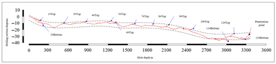
Figure 12.
Trajectory of ultra-long directional borehole.
Due to the fact that the 3353 m borehole is a through hole, the directional long borehole negative pressure test can be divided into two situations: (1) single-sided extraction, that is, drilling extraction on one side of the five-panel area; and (2) bilateral sampling, i.e., simultaneous sampling on both sides of the five-plate area and two-plate area. The on-site measured changes in negative pressure during drilling and extraction are shown in Figure 13.
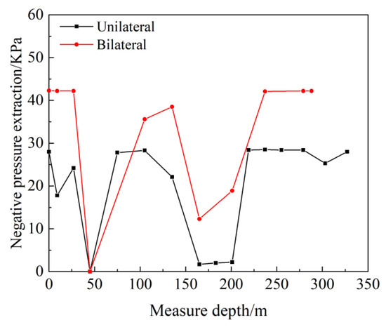
Figure 13.
Distribution and variation patterns of negative pressure along the path within the borehole.
Figure 13 indicates that when gas is extracted from both ends of the borehole, the negative pressure values within the borehole are generally higher compared to unilateral extraction. The maximum negative pressure at the borehole opening reaches 42.5 kPa, which is 13.9 kPa higher than the measured value during unilateral extraction, representing an increase of 48.6%. The patterns of negative pressure change for both extraction methods are basically consistent. From the borehole opening to the deeper parts, the negative pressure for gas drainage exhibits a “W”-shaped trend. The negative pressure at the borehole opening and the bottom shows little variation. At a depth of 45 m, the measured negative pressure value is 0 kPa. During on-site rod retrieval, a significant amount of water was found in the drill rod extracted from 45 m depth, indicating that accumulated water affected the negative pressure test results. The negative pressure for gas drainage in the water-logged section was relatively low, and there was little variation in the negative pressure at both ends of the water-logged section. This corroborates the conclusion from numerical simulations that, over a long period of gas drainage, the negative pressure within the borehole does not differ significantly from that at the borehole opening. Within the tested borehole depth range of 327 m, the negative pressure drop is relatively low, and the loss is minimal. Due to limitations of the experimental equipment, the negative pressure distribution in deeper regions has not been tested yet.
At present, the testing technology has been tested on site for 327 m, and on-site experiments are being conducted at Baode Coal Mine in Shanxi Province. Currently, negative pressures at depths greater than 400 m are being studied and measured on site.
This technology may be implemented in multiple fields of coal mine gas extraction. For different coal seams, both through-layer drilling and along-layer drilling can be used. This technology can be applied to fields with more complex geological conditions, as well as negative pressure testing in shale gas development or pressure testing in gas pipelines.
To obtain the time-varying pattern of negative pressure at different depths within a single borehole, on-site measurements of negative pressure were taken at 1 min intervals. When the data remained unchanged for three consecutive minutes, the negative pressure was deemed stable. The changes in negative pressure over time at different borehole depths are illustrated in Figure 13.
Figure 14 shows that the negative pressure stabilizes rapidly in the vicinity of the borehole opening and the bottom. Generally, it reaches its peak within 3 to 10 min. From the borehole opening to the bottom, the process of negative pressure stabilization exhibits a “fast-slow-fast” trend. From a depth of −3 m to 45 m, the time taken for negative pressure stabilization ranges from 3 to 7 min, with the longest stabilization time occurring at a depth of 27 m. At a depth of 45 m, water accumulation caused blockage in the pressure measuring tube, resulting in the measured data consistently showing 0 kPa. From a depth of 105 m to 135 m, the time required for negative pressure stabilization increases, with a stabilization time of 41 min at 105 m. Subsequently, from 135 m to the bottom, the speed of negative pressure stabilization accelerates again, and the time required for negative pressure stabilization at the bottom is 12 min.
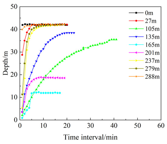
Figure 14.
Diagram of the time-varying patterns of negative pressure at different depths in a single borehole.
A comparison of the negative pressure for gas drainage under single-sided and double-sided extraction conditions at a depth of 279 m is shown in Figure 14.
Figure 15 indicates that the rate of pressure stabilization is faster during double-sided extraction compared to single-sided extraction. Additionally, the negative pressure within the borehole is higher during double-sided extraction than during single-sided extraction. This indicates that double-sided extraction contributes to enhancing the pre-drainage efficiency of coal seam gas.
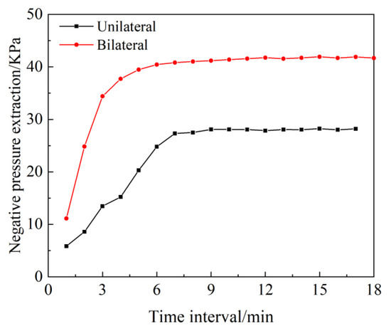
Figure 15.
Comparison of time-varying patterns of negative pressure between single-sided and dual-sided extraction.
6. Conclusions
(1) This study analyzes the changes in negative pressure during directional drilling and establishes a theoretical model to guide the design of drilling depth for gas extraction in the future.
(2) The gas flow velocity within the drainage borehole gradually increases from the bottom to the opening, with the flow velocity at the bottom remaining approximately constant at 0.17 m/s. As the drainage duration increases, the gas flow velocity within the borehole gradually decreases. The closer the location is to the borehole opening, the greater the velocity attenuation. Eventually, the flow velocities within the borehole tend to become uniform.
(3) Borehole collapse significantly alters the negative pressure distribution within the borehole, particularly during the initial stage of drainage. In the collapsed section (100–150 m), the drainage negative pressure decreases from 31.81 kPa to 20.87 kPa, with a negative pressure loss of 21.88 kPa per hundred meters, which is nine times that of an intact borehole. As the drainage duration extends, the negative pressure in the collapsed section gradually recovers, but the recovery time is longer than that of an intact borehole.
(4) The field test results are generally consistent with the numerical simulation results. When using bilateral drainage, the negative pressure values within the borehole are generally higher than those with unilateral drainage. From the opening to the deeper parts of the borehole, the drainage negative pressure exhibits a “W”-shaped variation trend, with minimal changes in negative pressure at the opening and the bottom. At a depth of 45 m, the negative pressure value drops to 0 kPa due to water accumulation, and there is little variation in the drainage negative pressure at both ends of the water-accumulated section.
(5) The negative pressure stabilizes rapidly near the opening and the bottom of the borehole, typically reaching its peak within 3–10 min. From the opening to the bottom, the negative pressure stabilization process exhibits a “fast-slow-fast” variation trend. Bilateral drainage results in a faster pressure stabilization rate and higher negative pressure within the borehole compared to unilateral drainage, indicating that bilateral drainage enhances the pre-drainage effect of coal seam gas.
Author Contributions
J.L., Conceptualization, Investigation, Methodology, Writing—original draft; Q.Z., Methodology, Writing—review and editing; J.W., Methodology, Writing—review and editing. All authors have read and agreed to the published version of the manuscript.
Funding
National Natural Science Foundation of China Youth Project (52204261), General Projects of Chongqing Natural Science Foundation (CSTB2023NSCQ-MSX0577), National Key Research and Development Program (2024YFC3013805), Key Science and Technology Project of Ministry of Emergency Management of the People’s Republic of China (2024EMST070703).
Data Availability Statement
The original contributions presented in this study are included in the article material. Further inquiries can be directed to the corresponding author.
Conflicts of Interest
The authors declare no conflicts of interest.
Nomenclature
| G | shear modulus |
| v | Poisson’s ratio |
| δij | Kronecker delta |
| K | bulk modulus |
| E | elastic modulus |
| Ks | bulk modulus |
| p | gas pressure |
| fi | volumetric stress tensor |
| s | adsorption-induced swelling strain per unit volume of coal |
| T | temperature |
| Ca | mass concentration of adsorbed gas contained in the coal seam per unit volume |
| ρg | density of gas at pressure p |
| JC | diffusion flux of gas passing through a unit area |
| ϕ | porosity |
| V | seepage velocity of gas |
| k | permeability of the coal seam |
| μ | dynamic viscosity of gas |
| D | diffusion coefficient |
| Mg | molecular weight of the gas |
| R | universal gas constant |
| Z | compressibility factor |
| Cf | free gas content per unit volume of coal |
| ρn | gas density under standard atmospheric pressure |
| A | ash content |
| W | moisture content |
| a | ultimate adsorption capacity of the coal body |
| b | Langmuir pressure constant for coal |
| ρc | apparent density of the coal body |
| a1, a2, a3, b1, b2 | data determined through gas adsorption experiments |
| εV | volumetric strain of coal |
| ϕ0 | initial porosity |
| β | thermal expansion coefficient of coal |
| ΔT | absolute temperature change |
| T0 | initial temperature of the coal body |
| Δp | change in gas pressure |
| P0 | original coal seam gas pressure |
| εs | adsorption expansion strain |
| Vm | molar volume of gas |
| λs | thermal conductivity of the coal skeleton |
| Cs | specific heat of the coal skeleton |
| ρc | density of the coal skeleton |
| qm | energy generated per unit volume of skeleton per unit time |
| λg | thermal conductivity of gas |
| Cg | specific heat of gas |
| ρg | density of gas |
| qg | energy generated per unit volume of gas per unit time |
| (V▽)T | convective term representing the temperature change caused by the movement of fluid particles |
| Qm | total gas flow rate |
| pm | pressure |
| vm | flow velocity |
| qm | gas flow rate |
| hm | resistance loss at a distance of x from the borehole |
| fi | resistance coefficient along the extraction borehole |
| Q(x) | gas extraction flow rate inside the borehole at a distance of x from the borehole opening |
| q(x) | gas flow rate that flows into the interior of the borehole from the borehole wall to the micro element segment |
| d | diameter of the gas extraction borehole |
| d’ | equivalent diameter after deformation of the gas extraction borehole |
| ξ | local resistance coefficient |
| ε | roughness of the pipe wall |
| Re | Reynolds number |
| v | gas flow velocity inside the hole |
| L | characteristic length of the fluid |
| μ | dynamic viscosity of gas |
| ρ | gas density inside the hole |
References
- Li, S.; Qin, Y.; Tang, D.; Shen, J.; Wang, J.; Chen, S. A comprehensive review of deep coalbed methane and recent developments in China. Int. J. Coal Geol. 2023, 279, 104369. [Google Scholar] [CrossRef]
- Mohamed, T.; Mehana, M. Coalbed methane characterization and modeling: Review and outlook. Energy Sources Part A Recovery Util. Environ. Eff. 2025, 47, 2874–2896. [Google Scholar] [CrossRef]
- Li, L.; Liu, D.; Cai, Y.; Wang, Y.; Jia, Q. Coal structure and its implications for coalbed methane exploitation: A review. Energy Fuels 2020, 35, 86–110. [Google Scholar] [CrossRef]
- Kędzior, S.; Teper, L. Occurrence and Potential for Coalbed Methane Extraction in the Depocenter Area of the Upper Silesian Coal Basin (Poland) in the Context of Selected Geological Factors. Energies 2024, 17, 2592. [Google Scholar] [CrossRef]
- Altowilib, A.; AlSaihati, A.; Alhamood, H.; Alafnan, S.; Alarifi, S. Reserves estimation for coalbed methane reservoirs: A review. Sustainability 2020, 12, 10621. [Google Scholar] [CrossRef]
- Kędzior, S.; Teper, L. Coal Properties and Coalbed Methane Potential in the Southern Part of the Upper Silesian Coal Basin, Poland. Energies 2023, 16, 3219. [Google Scholar] [CrossRef]
- Uliasz-Misiak, B.; Misiak, J.; Lewandowska-Śmierzchalska, J.; Matuła, R. Environmental risk related to the exploration and exploitation of coalbed Methane. Energies 2020, 13, 6537. [Google Scholar] [CrossRef]
- Sidorenko, S.; Trushnikov, V.; Sidorenko, A. Methane emission estimation tools as a basis for sustainable underground mining of gas-bearing coal seams. Sustainability 2024, 16, 3457. [Google Scholar] [CrossRef]
- Zhou, K.; Sun, F.; Yang, C.; Qiu, F.; Wang, Z.; Xu, S.; Chen, J. Evaluation of Deep Coalbed Methane Potential and Prediction of Favorable Areas within the Yulin Area, Ordos Basin, Based on a Multi-Level Fuzzy Comprehensive Evaluation Method. Processes 2024, 12, 820. [Google Scholar] [CrossRef]
- Li, J.; Wen, M.; Jiang, Z.; Xian, L.; Liu, J.; Chen, J. Development and characterization of a surfactant responsive to redox conditions for gas recovery in foam drainage. Sci. Rep. 2025, 15, 511. [Google Scholar] [CrossRef]
- Tao, C.; Li, Y.; Wang, Y.; Ni, X.; Wu, X.; Zhao, S. Characteristics of deep coal reservoir and key control factors of coalbed methane accumulation in linxing area. Energies 2023, 16, 6085. [Google Scholar] [CrossRef]
- Smirnova, A.; Varnavskiy, K.; Nepsha, F.; Kostomarov, R.; Chen, S. The Development of Coal Mine Methane Utilization Infrastructure within the Framework of the Concept “Coal-Energy-Information”. Energies 2022, 15, 8948. [Google Scholar] [CrossRef]
- Olajossy, A.; Cieślik, J. Why coal bed methane (CBM) production in some basins is difficult. Energies 2019, 12, 2918. [Google Scholar] [CrossRef]
- Wang, K.; Zhao, X.; Li, S. Study on the distribution law and application of negative extraction pressure in bedding borehole. Min. Saf. Environ. Prot. 2021, 48, 81–86. [Google Scholar]
- Zhang, X.B.; Wang, W.Y.; Shen, S.S. Experimental study on distribution of negative pressure and flow rate under conditions of deformation and instability of boreholes. Coal Sci. Technol. 2020, 48, 45–51. [Google Scholar]
- Zhang, X.; Wang, H.; Yang, M.; Wang, P.; Han, L. Study and application on influence mechanism of instability and collapse of drainage borehole on gas drainage. J. China Coal Soc. 2023, 48, 3102–3115. [Google Scholar]
- Liu, J.; Liu, Z.; Wei, Y.; Chen, X. Change characteristics of negative drainage pressure along the drill hole: Theoretical analyses and field tests. ACS Omega 2022, 7, 19948–19956. [Google Scholar] [CrossRef]
- Cheng, X.; Cheng, C.; Wang, H.; Xiao, L.; Ma, X. Research and Application of Gas Drainage Negative Pressure Regulation Method Considering Permeability Differences. Processes 2025, 13, 1236. [Google Scholar] [CrossRef]
- Zhang, C.; Xu, J.; Peng, S.; Li, Q.; Yan, F.; Chen, Y. Dynamic behavior of gas pressure and optimization of borehole length in stress relaxation zone during coalbed methane production. Fuel 2018, 233, 816–824. [Google Scholar] [CrossRef]
- Dikken, B.J. Pressure drop in horizontal wells and its effect on production performance. J. Pet. Technol. 1990, 42, 1426–1433. [Google Scholar] [CrossRef]
- Li, J.; Wen, M.; Jiang, Z.; Gao, S.; Xiao, X.; Xiang, C.; Tao, J. Formulation and characterization of surfactants with antibacterial and corrosion-inhibiting properties for enhancing shale gas drainage and production. Sci. Rep. 2025, 15, 2376. [Google Scholar] [CrossRef] [PubMed]
- Hill, A.D.; Zhu, D. The relative importance of wellbore pressure drop and formation damage in horizontal wells. SPE Prod. Oper. 2008, 23, 232–240. [Google Scholar] [CrossRef]
- Wen, J.; Yang, M.; Qi, W.; Wang, J.; Yuan, Q.; Luo, W. Experimental analysis and numerical simulation of variable mass flow in horizontal wellbore. Int. J. Heat Technol. 2018, 36, 309–318. [Google Scholar] [CrossRef]
- Yue, P.; Yang, H.; He, C.; Yu, G.M.; Sheng, J.J.; Guo, Z.L.; Guo, C.Q.; Chen, X.F. Theoretical approach for the calculation of the pressure drop in a multibranch horizontal well with variable mass transfer. ACS Omega 2020, 5, 29209–29221. [Google Scholar] [CrossRef] [PubMed]
- Liu, J.; Wu, Z.; Lu, P.; Liu, Z.; Su, M. Study on effective extraction radius of directional long borehole and analysis of the influence mechanism. ACS Omega 2023, 8, 2344–2356. [Google Scholar] [CrossRef]
- Liu, J.; Zhang, L.W.; Wang, L.; Chen, X.J. Negative pressure distribution of variable mass flow in coal mine drainage boreholes. Energy Sources Part A Recovery Util. Environ. Eff. 2025, 47, 1650–1667. [Google Scholar] [CrossRef]
- Du, F.; Cui, W.; Wang, K. Study on Gas migration mechanism and multi-borehole spacing optimization in coal under negative pressure extraction. Processes 2023, 11, 259. [Google Scholar] [CrossRef]
- Xu, C.; Wang, J.; Du, C.; Zhou, A.; Wang, K. Simulation of attenuation mechanism of negative pressure along the hole length of long boreholes in gas drainage and its influencing factors. J. Min. Saf. Eng. 2021, 38, 419–428. [Google Scholar]
- Qi, Q.; Jia, X.; Zhou, X.; Zhao, Y. Instability-negative pressure loss model of gas drainage borehole and prevention technique: A case study. PLoS ONE 2020, 15, e0242719. [Google Scholar] [CrossRef]
- Tang, M.; Zhang, G.; He, S.; Kong, L.; Deng, F.; Lei, H. Analysis of seepage and temperature fields and their influence on collapse pressure while drilling in shale oil reservoirs. Geoenergy Sci. Eng. 2023, 231, 212410. [Google Scholar] [CrossRef]
- Li, K.Q.; Yin, Z.Y. State of the art of coupled thermo–hydro-mechanical–chemical modelling for frozen soils. Arch. Comput. Methods Eng. 2024, 32, 1039–1096. [Google Scholar] [CrossRef]
- Liu, N.; Li, N.; Wang, S.; Li, G.; Song, Z. A fully coupled thermo-hydro-mechanical model for fractured rock masses in cold regions. Cold Reg. Sci. Technol. 2023, 205, 103707. [Google Scholar] [CrossRef]
- Li, M.; Wu, Z.; Weng, L.; Zhang, F.; Zhou, Y.; Wu, Y. Cross-scale analysis for the thermo-hydro-mechanical (THM) effects on the mechanical behaviors of fractured rock: Integrating mesostructure-based DEM modeling and machine learning. Eng. Fract. Mech. 2024, 306, 110204. [Google Scholar] [CrossRef]
- Li, M.; Wu, Z.; Weng, L.; Liu, Q.; Chu, Z. Modelling Thermo-hydro-mechanical (THM) effect on the hydro-mechanical properties of granite in disposal system using an improved meso-structure-based DEM model. Rock Mech. Rock Eng. 2024, 57, 5129–5154. [Google Scholar] [CrossRef]
- Meng, T.; Liu, Z.; Wu, F.; Zhang, Z.; Liang, X.; He, Y.; Wu, X.; Yang, Y.; Gao, H. Coupled thermo-hydro-mechanical analysis of porous rocks: Candidate of surrounding rocks for deep geological repositories. J. Rock Mech. Geotech. Eng. 2025, 17, 3073–3092. [Google Scholar] [CrossRef]
- Yang, F.; Wang, G.; Hu, D.; Liu, Y.; Zhou, H.; Tan, X. Calibrations of thermo-hydro-mechanical coupling parameters for heating and water-cooling treated granite. Renew. Energy 2021, 168, 544–558. [Google Scholar] [CrossRef]
- Li, S.; Feng, X.T.; Zhang, D.; Tang, H. Coupled thermo-hydro-mechanical analysis of stimulation and production for fractured geothermal reservoirs. Appl. Energy 2019, 247, 40–59. [Google Scholar] [CrossRef]
- Yu, H.; Chen, W.; Gong, Z.; Tan, X.; Yang, D. Loading-unloading behavior of a clayey rock under thermo-hydro-mechanical conditions. Int. J. Rock Mech. Min. Sci. 2021, 148, 104966. [Google Scholar] [CrossRef]
- Xu, R.; Liao, L.; Liang, W.; Wang, H.; Zhou, Q.; Liu, W.; Chen, M.; Fang, B.; Wu, D.; Jin, H.; et al. Fast Removing Ligands from Platinum-Based Nanocatalysts by a Square-Wave Potential Strategy. Angew. Chem. Int. Ed. Engl. 2025, 5, e202509746. [Google Scholar]
- Liu, Y.; Zhou, L.; Wan, X.; Tang, Y.; Liu, Q.; Li, W.; Liao, J. Synthesis and Characterization of a Temperature-Sensitive Microcapsule Gelling Agent for High-Temperature Acid Release. ACS Omega 2024, 9, 20849–20858. [Google Scholar] [CrossRef]
- Zhang, Y.; Li, Y.; Zheng, H.; Fan, B. A novel fully coupled thermo-hydro-mechanical-damage model for hydraulic fracture propagation in fractured geothermal reservoirs. Comput. Geotech. 2025, 185, 107364. [Google Scholar] [CrossRef]
- Li, M.; Wu, Z.; Weng, L.; Zhou, Y.; Liu, Q. Evaluating the pore characteristics of granite in disposal system under thermo-hydro-mechanical (THM) coupling. Int. J. Rock Mech. Min. Sci. 2022, 160, 105237. [Google Scholar] [CrossRef]
- Song, G.; Song, X.; Xu, F.; Li, G.; Shi, Y.; Ji, J. Contributions of thermo-poroelastic and chemical effects to the production of enhanced geothermal system based on thermo-hydro-mechanical-chemical modeling. J. Clean. Prod. 2022, 377, 134471. [Google Scholar] [CrossRef]
Disclaimer/Publisher’s Note: The statements, opinions and data contained in all publications are solely those of the individual author(s) and contributor(s) and not of MDPI and/or the editor(s). MDPI and/or the editor(s) disclaim responsibility for any injury to people or property resulting from any ideas, methods, instructions or products referred to in the content. |
© 2025 by the authors. Licensee MDPI, Basel, Switzerland. This article is an open access article distributed under the terms and conditions of the Creative Commons Attribution (CC BY) license (https://creativecommons.org/licenses/by/4.0/).