Article

Computational Analysis of Two Micro-Vortex Generator Configurations for Supersonic Boundary Layer Flow Control

1
Department of Mathematics, West Texas A&M University, Canyon, TX 79016, USA
2
Department of Mathematics and Statistical Sciences, Jackson State University, Jackson, MS 39217, USA
3
Department of Mathematics, Brandeis University, Waltham, MA 02453, USA
*
Author to whom correspondence should be addressed.
Processes 2025, 13(9), 2818; https://doi.org/10.3390/pr13092818
Submission received: 17 August 2025 / Revised: 29 August 2025 / Accepted: 2 September 2025 / Published: 3 September 2025
(This article belongs to the Special Issue Transport Processes in Single- and Multi-Phase Flow Systems)

Abstract

The increasing demand for effective flow control in supersonic boundary layers, particularly for mitigating shock-wave boundary-layer interactions, underscores the need to explore optimized micro-vortex generator (MVG) configurations. This study investigates the aerodynamic performance of two different MVG configurations: a two-MVG setup with a pair of close parallel-positioned MVGs and a three-MVG arrangement that includes an additional upstream unit. Both are examined within a Mach 2.5 flow regime, aiming to improve mixing and energize the boundary layer. Large Eddy Simulations (LES) were performed using high-order numerical schemes. A newly developed vortex identification method was utilized to characterize vortex structures, while turbulent kinetic energy (TKE) metrics were integrated to quantify turbulence. Findings reveal that the two-MVG configuration produces regular, symmetric vortex pairs with limited interaction. This results in a steady increase in TKE and a thickened momentum boundary layer—indicative of notable energy loss. In contrast, the three-MVG setup generates more intricate and interactive vortex formations that significantly elevate TKE levels, rapidly expand the turbulent region, and reduce energy loss downstream. The peak TKE occurs before tapering slightly. Instantaneous flow analysis further highlights chaotic, hairpin-dominated vortex structures in the three-MVG case, compared to the more orderly ones observed in the two-MVG case. Overall, the three-MVG configuration demonstrates superior mixing and boundary-layer energization potential, albeit with greater structural complexity.

1. Introduction

Shock-wave boundary-layer interaction (SBLI) is a daunting challenge in supersonic aerodynamics, where shock waves interacting with the boundary layer induce flow separation, elevate drag, cause total pressure losses, and increase thermal loads on aircraft surfaces [1]. These effects undermine the aerodynamic efficiency, structural integrity, and operational stability of high-speed aircraft and propulsion systems, necessitating innovative flow control strategies to mitigate their impact. Micro-vortex generators (MVGs), compact passive devices typically spanning 10% to 80% of the boundary layer thickness, have emerged as effective tools for managing SBLI [2]. By generating a pair of counter-rotating streamwise vortices, MVGs energize the boundary layer, reduce flow separation, and promote flow attachment, offering advantages such as low drag penalty, non-intrusiveness, and seamless integration into aerodynamic surfaces, including wings, inlets, and nozzles.
Extensive research has investigated the aerodynamic performance of micro-vortex generators, particularly in isolated or widely spaced parallel configurations. Babinsky [2] conducted experiments across different MVG designs to evaluate the flow control effects. Sun [3] used particle image velocimetry (PIV) on the 3D turbulent flow behind the MVG in a supersonic boundary layer, capturing the intricate wake dynamics. Wang [4] employed nano-tracer planar laser scattering (NPLS) and PIV to obtain detailed flow data in a low-noise supersonic wind tunnel. Zhang [5] explored the induced velocity and the trajectory of the vortices generated by micro-vortex generators by using the point vortex model. Liu [6] investigated MVG-based suppression of supersonic jet noise, highlighting the sensitivity of performance to MVG placement. His findings showed that MVGs effectively weaken downstream shock cells, thereby improving overall flow control efficiency. Xue [7] investigated the wake structures of micro-ramp and micro-manes numerically. Moreover, Wang [8] employed Large Eddy Simulation (LES) and explored wake organization downstream of ramp-type MVGs at Mach 2.7, featuring their role in the fluid redistribution. In our earlier studies [9], simulations explored supersonic boundary layers influenced by MVGs at different Mach numbers. The analysis identified complex vortex structures, especially ring-like vortices, which significantly affect SBLI and alter ramp shock dynamics. A V-shaped separation zone was detected along the wall, resulting from the interplay between these vortices and the ramp shock, aiding flow separation reduction at the ramp corner. These findings highlight the paramount role of MVG-induced vortex structures in controlling supersonic boundary layers.
Despite the focus on isolated or widely spaced parallel configurations, the flow under more complicated MVG array configurations remains almost underexplored in the context of high-speed flow control. Nishantt [10] examined MVG spacing effects in shock-wave boundary-layer interactions, suggesting that array configurations could significantly alter vortex strength and flow mixing. Similarly, Saleem [11] investigated dual MVG arrays in supersonic nozzles, demonstrating that they modify shock-cell structures and enhance mixing, which reduces jet noise. Liu [6] reported comparable findings, noting that MVG arrays in supersonic jets alter shock patterns and shear layer dynamics, promoting vortex interactions. Additionally, Lu [12] provided experimental data on the near wake of MVGs in supersonic flow, offering insights into vortex evolution in array configurations. Reddy [13] investigated the optimum design of a row of MVG blade pairs for planar symmetric diffusers with different opening angles. These studies, while often focused on nozzle or jet applications, underscore the potential for non-tandem MVG arrangements to produce unique flow interactions in boundary layer flows, yet specific investigations into parallel or three-MVG setups in flat-plate geometries are scarce. Our previous study [14] examined tandem MVGs within a Mach 2.5 supersonic boundary layer. The results revealed that while tandem arrangements generate intricate vortex interactions—marked by both spanwise and streamwise vortex merging, they also lead to a doubling of boundary layer energy loss due to mutual vortex cancelation. This behavior can undermine the overall effectiveness of flow control. These findings underscore the pivotal role MVG arrangement plays in shaping boundary layer dynamics and motivate the exploration of alternative configurations with the potential to improve control outcomes.
This study addresses the research gap on more complicated MVG configurations by examining two MVG configurations in a supersonic boundary layer at Mach 2.5: (1) two MVGs arranged closely in parallel, positioned side by side, and (2) a three-MVG configuration, with the third MVG placed upstream of the midpoint between the two parallel MVGs. To investigate the flow fields, especially the vortex structures influenced by these configurations, we employ LES, which is well-suited for capturing the unsteady, turbulent flow structures inherent in supersonic boundary layers. The LES framework utilizes a fifth-order Weighted Essentially Non-Oscillatory (WENO) scheme [15] for spatial discretization and a third-order Total Variation Diminishing (TVD) Runge–Kutta scheme for time marching, solving the unfiltered Navier–Stokes equations. The Liutex vortex identification method [16] is applied to visualize and analyze vortex structures, providing detailed insights into their evolution and interactions.
After introducing the paper in Section 1, the remainder is organized as follows: Section 2 details the numerical setup and computational methods, Section 3 presents the results and discussion and Section 4 offers concluding remarks.

2. Materials and Methods

2.1. Numerical Methods

This study deploys LES to solve the Navier–Stokes (NS) equations, modeling the fluid flow in a supersonic boundary layer. The Navier–Stokes equations, derived from the conservation principles of mass, momentum, and energy, are formulated as follows:
ρ t + ( ρ u ) = 0
( ρ u ) t + ( ρ u u ) = ( σ )
( ρ E ) t + ( ρ E ) u ( k T ) ( σ u ) = 0
with
E = e + u u 2
σ = p + 2 3 μ ( u ) I + μ u + ( u ) T
where ρ represents the density of the fluid, u the velocity vector, E the total energy, σ the internal shear stress, e the internal energy per unit mass, p the pressure, T the temperature, k the thermal conductivity, and μ the dynamic viscosity.
To close the Navier–Stokes system, we solve two relations: the equation of state for a thermally perfect gas and the internal energy equation, described as follows:
p = ρ R T
e = C v T  
where R is a gas constant and C v is a specific heat capacity.
In this study, a fifth-order bandwidth-optimized WENO scheme [13] is employed, and monotone integrated LES code was adopted to solve the Navier–Stokes equations, with numerical dissipation used as the sub-grid stress model [17,18]. In addition, time marching is performed using an explicit third-order Total Variation Diminishing (TVD) Runge–Kutta scheme.

2.2. Case Setup

This study employs LES to investigate two MVG configurations in a supersonic boundary layer at Mach 2.5 and Reynolds number 5760 with the configurations denoted as follows:
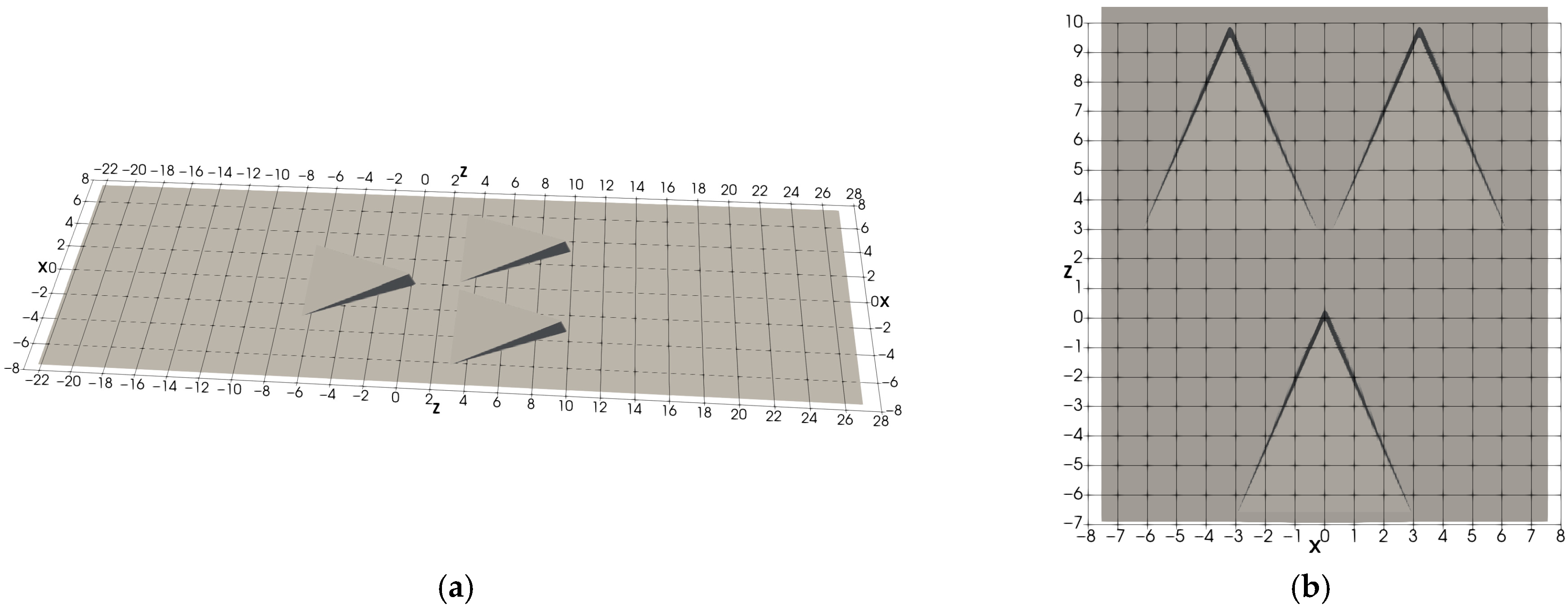
  • The two-MVG case: Two MVGs are placed next to each other in the spanwise direction (X), see Figure 1. The computational domain spans 15 h × 24 h × 39.6 h (where h is the MVG height) in the spanwise (X), wall-normal (Y), and streamwise (Z) directions, respectively, with a grid resolution of 269 × 200 × 846.
  • The three-MVG case: Three MVGs are arranged with two MVGs positioned identically to the Two-MVG case and a third MVG placed upstream at the midpoint between them, with a streamwise offset of 3h, see Figure 2. The computational domain spans 15 h × 24 h × 49 h in the spanwise (X), wall-normal (Y), and streamwise (Z) directions, respectively, with a grid resolution of 269 × 200 × 1091.
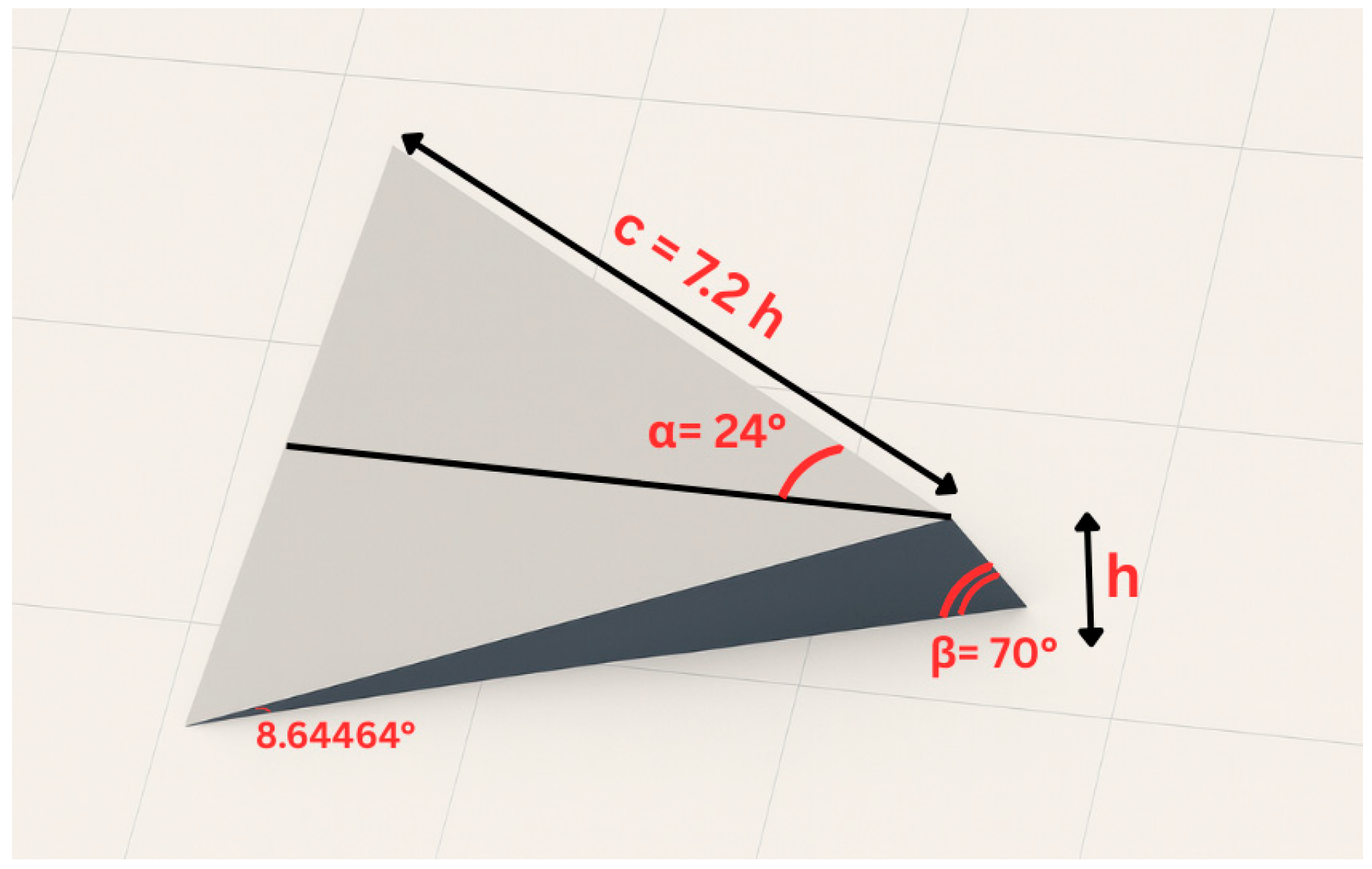
The geometry of a single micro-vortex generator (MVG) is shown in Figure 3. The MVG trailing edge is inclined at 70° to facilitate mesh generation, with other dimensions matching those used in prior experimental studies [2]. The inlet boundary layer thickness, δ 0 , is set to 2h, consistent with experimental data and our previous simulations [9]. At the wall, adiabatic, zero-pressure-gradient, and no-slip boundary conditions are applied. Non-reflecting boundary conditions are enforced at the upper boundary to minimize wave reflections. Periodic boundary conditions are imposed at the spanwise boundaries. To improve the resolution of vortex interactions, particularly the ring-like vortices generated by the MVG, a laminar inlet profile is utilized. A non-reflecting boundary condition is also applied at the outflow to ensure numerical stability. The details of the numerical schemes, methods and validations can be found in [9].

3. Results

This section employs the Liutex method [16], a novel approach for vortex identification, to identify and analyze the vortex structures generated by the MVGs. Liutex utilizes RS decomposition to distinguish non-dissipative rigid rotation from dissipative shear, as described below:
ω = R + S  
R = ω · r ω · r 2 4 λ c i 2 r
where r is the real eigenvector of u and ω · r > 0 .

3.1. Mean Flow Structures

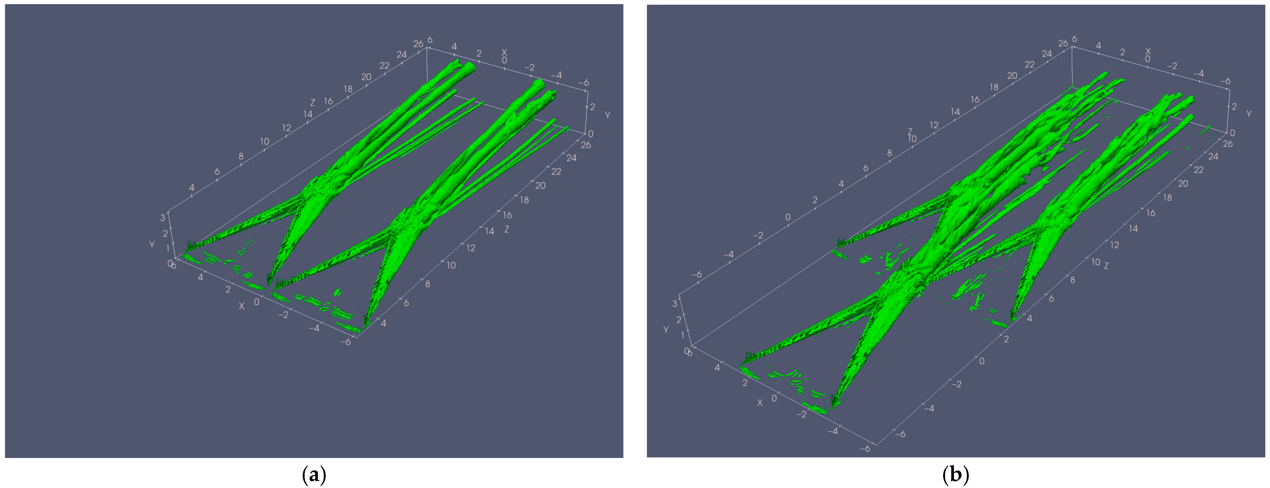
To investigate the mean flow characteristics of each configuration, time-averaged fields are derived from 20,000 time steps. Figure 4 presents the vortex structures generated by the MVGs within these averaged fields, visualized through Liutex iso-surfaces at a threshold of R = 0.3 . In the two-MVG case, each MVG produces a distinct vortex structure, a pair of large counters rotating streamwise primary vortices and secondary vortices from the wall separation, characterized by highly regular and symmetrical forms. Significantly, the vortices from the two closely positioned MVGs exhibit little to no interaction. Conversely, in the three-MVG case, the vortex structure generated by the third MVG positioned upstream passes through the central region between the two parallel MVGs, leading to notable influence on the vortices generated by MVGs downstream. Although these primary vortex structures do not intensively interact together in the computational domain, as shown in Figure 2b, this interaction distorts and breaks the primary vortices from the rear two MVGs into smaller, irregular structures, with similar disruptive effects observed in the induced vortices near the wall.
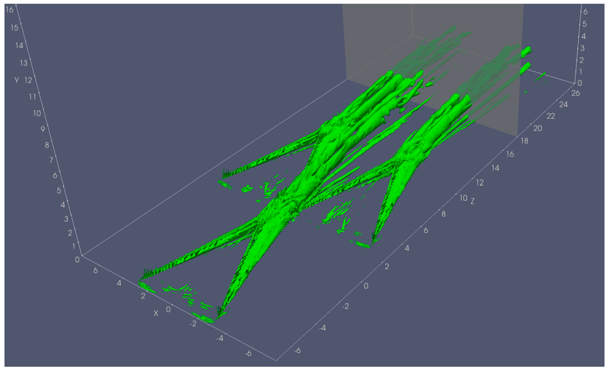
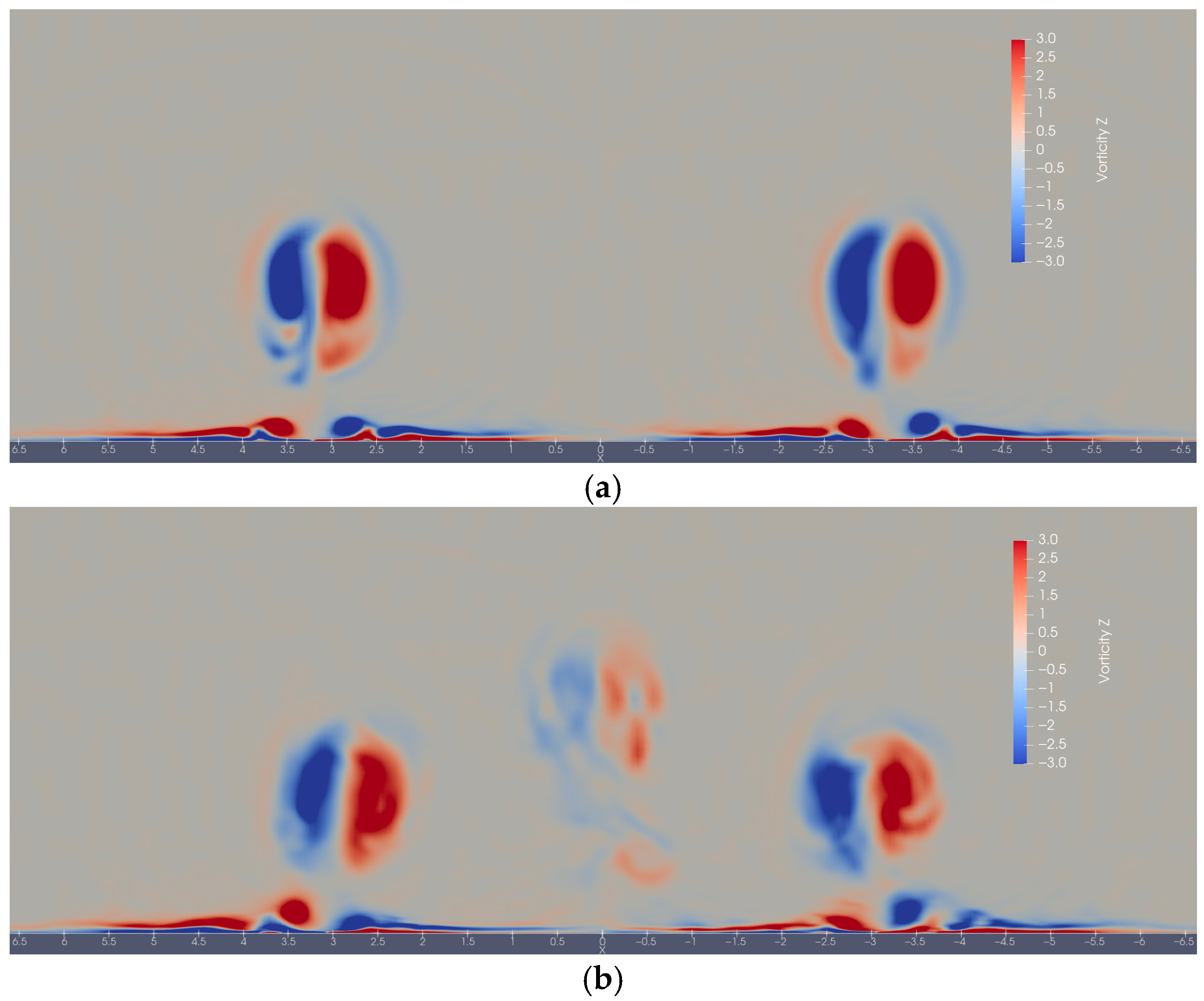
To examine the vorticity and flow characteristics in detail, an XY plane is selected at Z = 18h. Figure 5 illustrates the position of this plane within the three-MVG case, and a corresponding plane is similarly defined for the two-MVG case. Figure 6 presents the distribution of streamwise vorticity on the Z = 18h plane from both cases. In the two-MVG case, the streamwise vorticity associated with the primary vortex pair exhibits a symmetric and regular pattern, a regularity that extends to the smaller vortical structures near the wall, confirming minimal to no interaction between them. In contrast, the three-MVG case reveals a more complex vorticity field, where the vortices generated by the third MVG interact with those from the two parallel MVGs, resulting in a decentralized distribution of streamwise vorticity. Specifically, the vortices originating from the two parallel MVGs in the three-MVG case appear to tilt and converge, influenced by the upstream vortices from the third MVG. This behavior is further corroborated by the streamlines depicted in Figure 7.
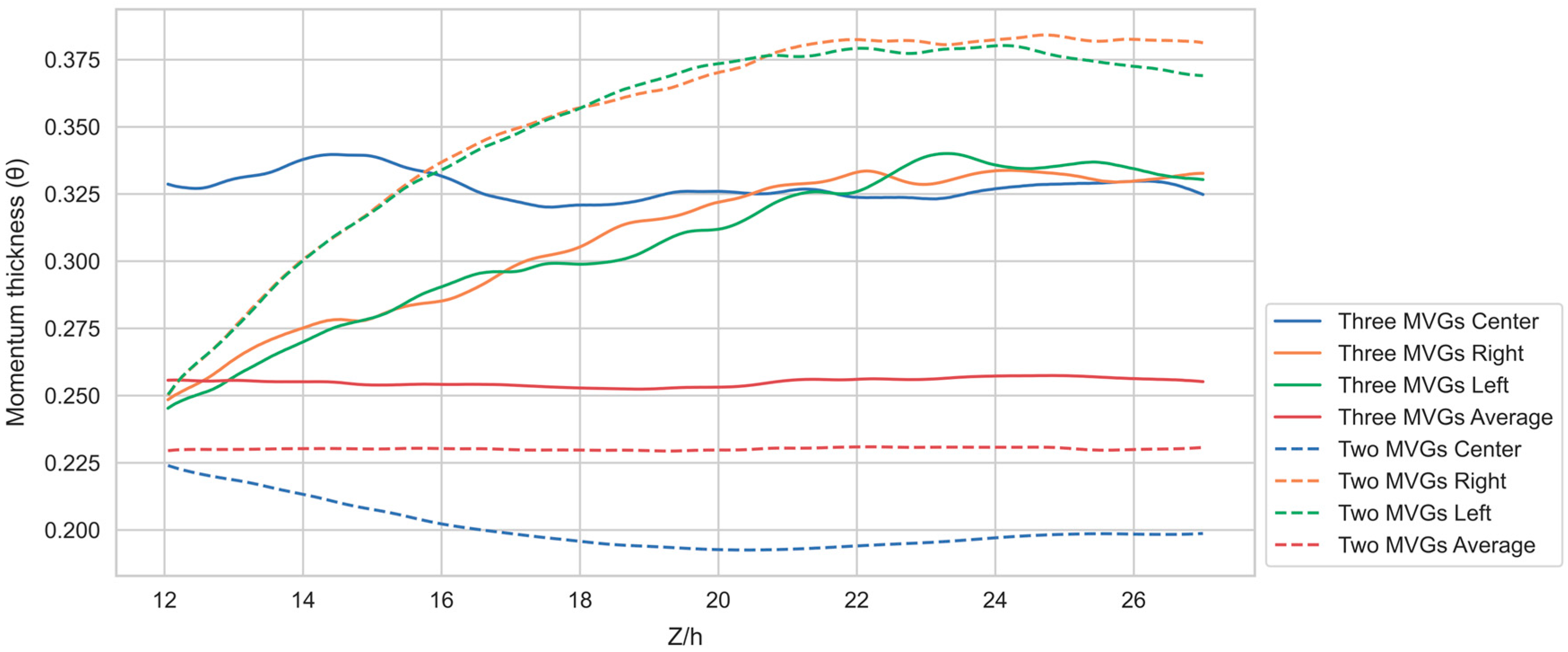
To evaluate the impact of the MVG configurations on boundary layer properties, the momentum boundary layer thickness is computed along the streamwise direction (Z). Figure 8 illustrates the positions of three blocks in the three-MVG case, where momentum thicknesses are averaged to represent the mean boundary layer thickness downstream of each MVG. Equivalent blocks are defined for the two-MVG case to ensure consistency. Figure 9 presents the averaged momentum boundary layer thickness downstream of the MVGs, with solid lines corresponding to the three-MVG case and dashed lines to the two-MVG case. The blue lines indicate the momentum thickness behind the center MVG, green lines behind the left MVG, and orange lines behind the right MVG. Intuitively, the averaged momentum thickness in the center block of the three-MVG case exceeds that of the two-MVG case, due to energy dissipation induced by the vortices from the center MVG. A significant finding emerges from comparing the momentum thickness behind the two parallel MVGs: the two-MVG case exhibits a thicker momentum boundary layer, suggesting that the addition of the third MVG reduces energy loss from the original parallel MVGs.

3.2. Turbulence Analysis

To quantify the turbulent characteristics induced by the MVG configurations, this section examines the Turbulent Kinetic Energy (TKE) derived from the LES data. TKE, defined as the mean kinetic energy per unit mass associated with velocity fluctuations, provides a robust metric to assess the intensity and distribution of turbulence within the supersonic boundary layer. The calculation formulas are as follows.
u r m s = 1 N n = 1 N u n u _ 2
k = 1 2 ρ _ u r m s 2 + v r m s 2 + w r m s 2
where u n is the spanwise velocity at time step n, u _ is the time-averaged spanwise velocity, N is the total number of time steps, the subscription rms represents root mean square, ρ _ is the time-averaged density, and k is the TKE. The formulas to calculate v r m s and w r m s are similar to u r m s .
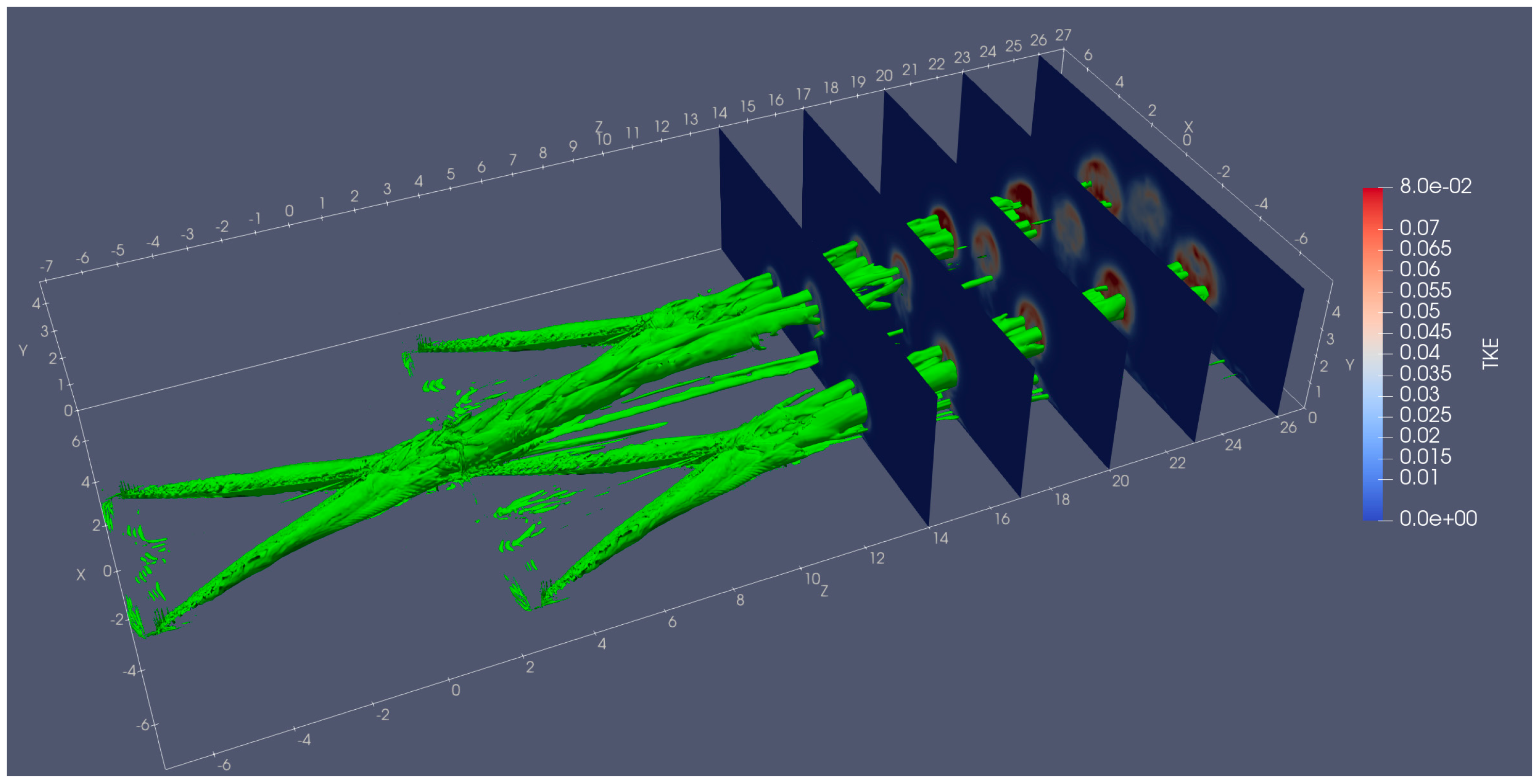
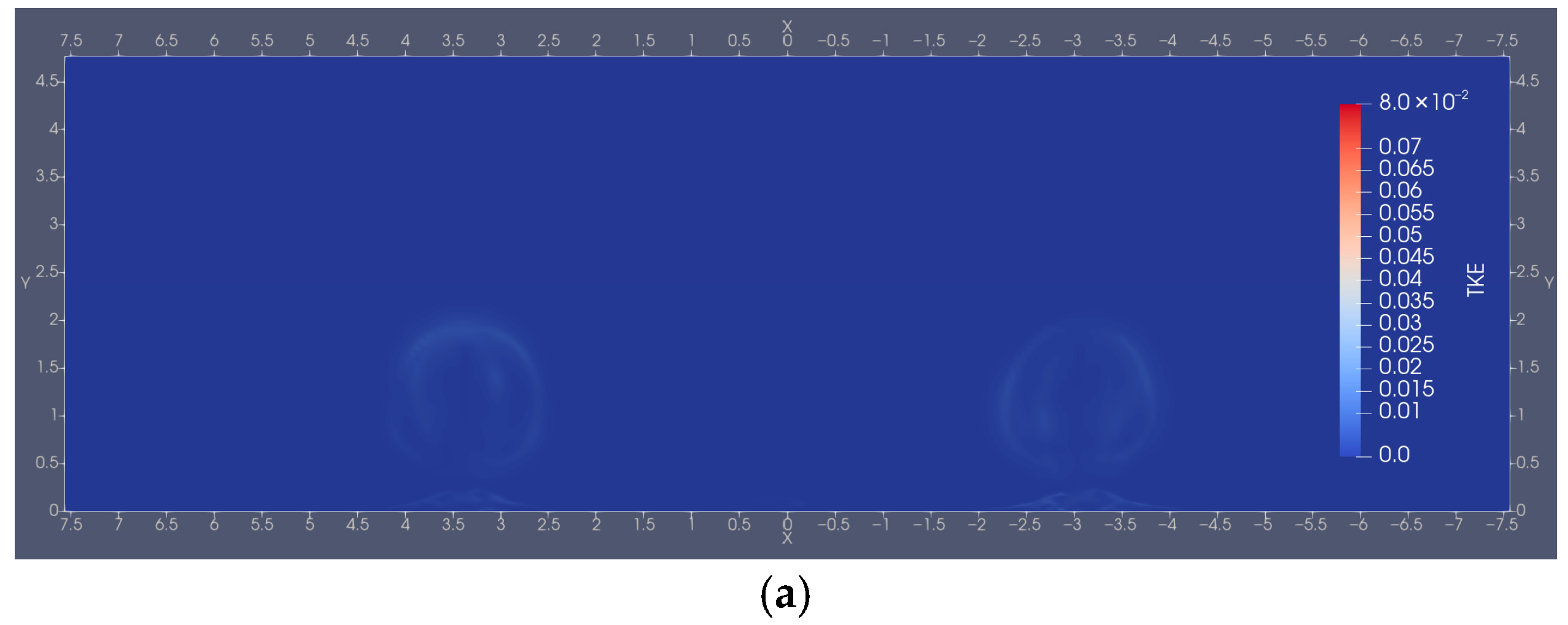
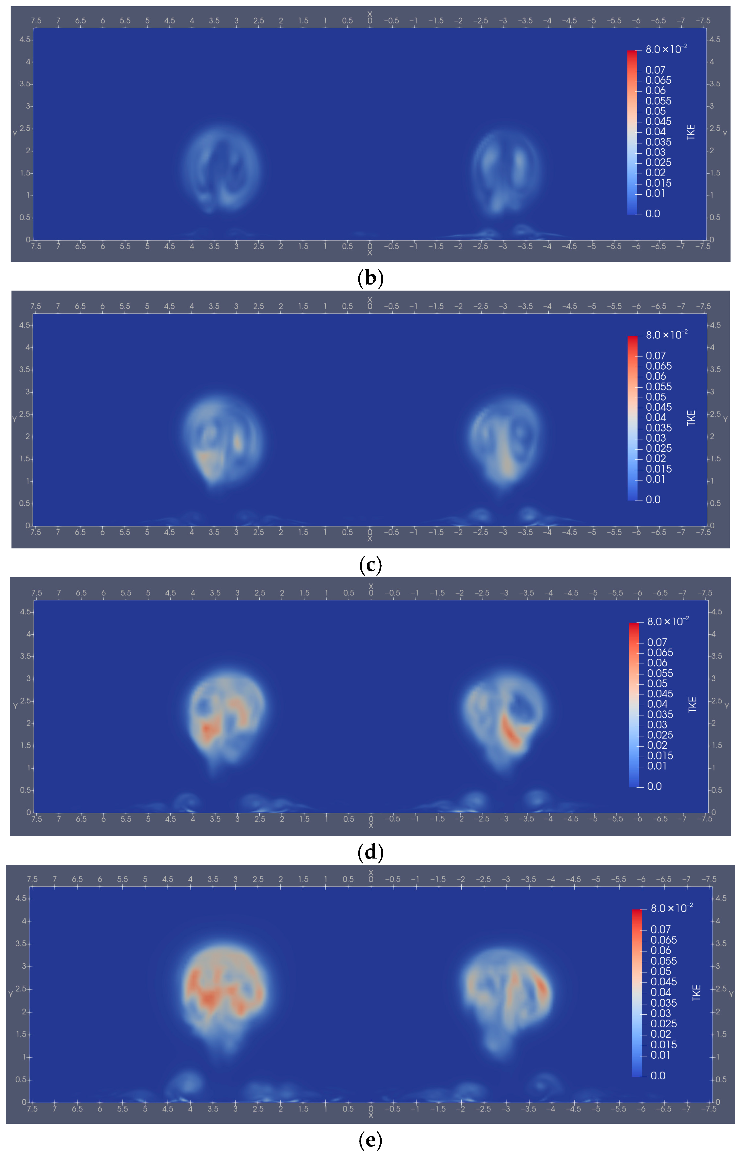
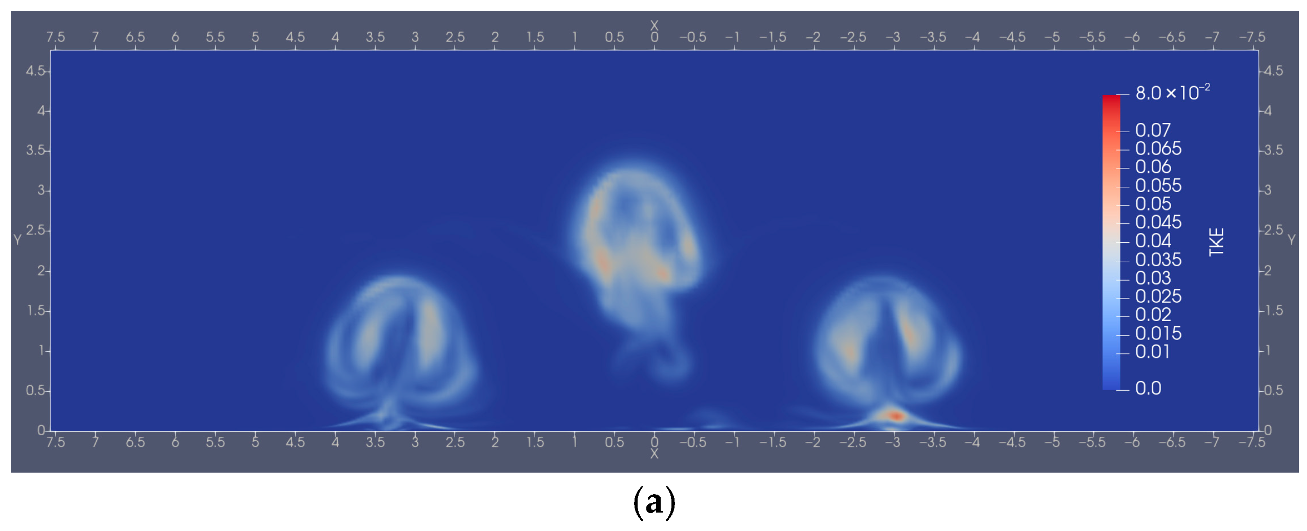
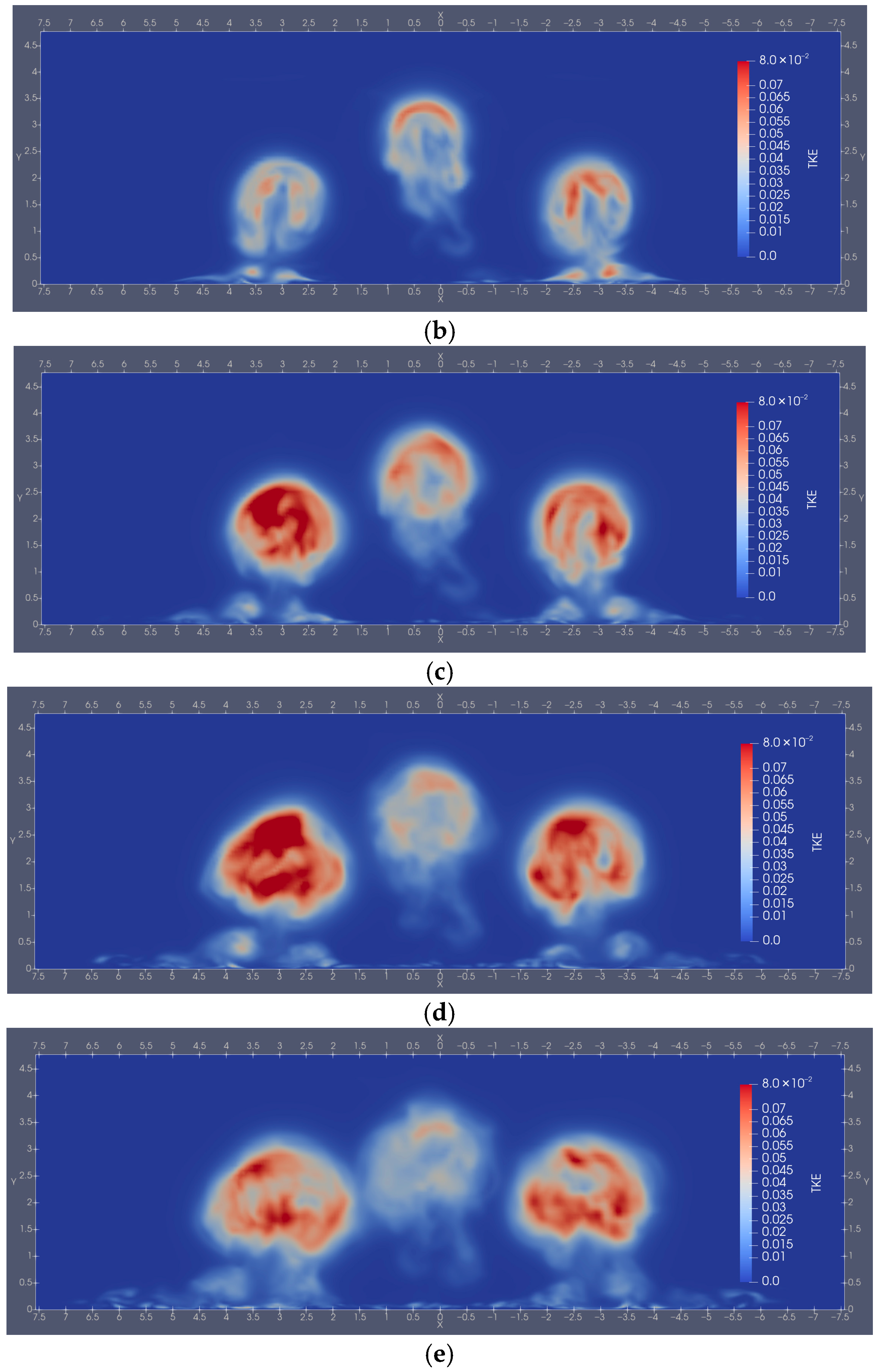
Figure 10 presents the TKE distribution on various XY planes at different streamwise positions for the three-MVG case, with corresponding planes applied to the two-MVG case. Figure 11 provides a detailed view of the TKE distribution on these planes for the two-MVG case, while Figure 12 illustrates the same for the three-MVG case. The overall TKE magnitude in the three-MVG case exceeds that of the two-MVG case, reflecting enhanced turbulent mixing driven by the additional upstream MVG. This increased turbulence intensity, particularly evident in the decentralized vorticity and distorted vortex structures observed at Z = 23h, suggests greater energy dissipation and potential effectiveness in energizing the boundary layer to mitigate separation. Notably, regions of high TKE in the three-MVG case expand more rapidly compared to those in the two-MVG case. Additionally, the TKE in the two-MVG case continues to increase with greater distance from the MVGs, whereas in the three-MVG case, it rises to a peak before exhibiting a slight decline.
To verify the change in TKE along the streamwise direction, TKE is integrated over cross-sectional planes (XY planes) to quantify total turbulent energy at different streamwise locations, as follows.
K t o t a l z =    k x , y , z d x   d y
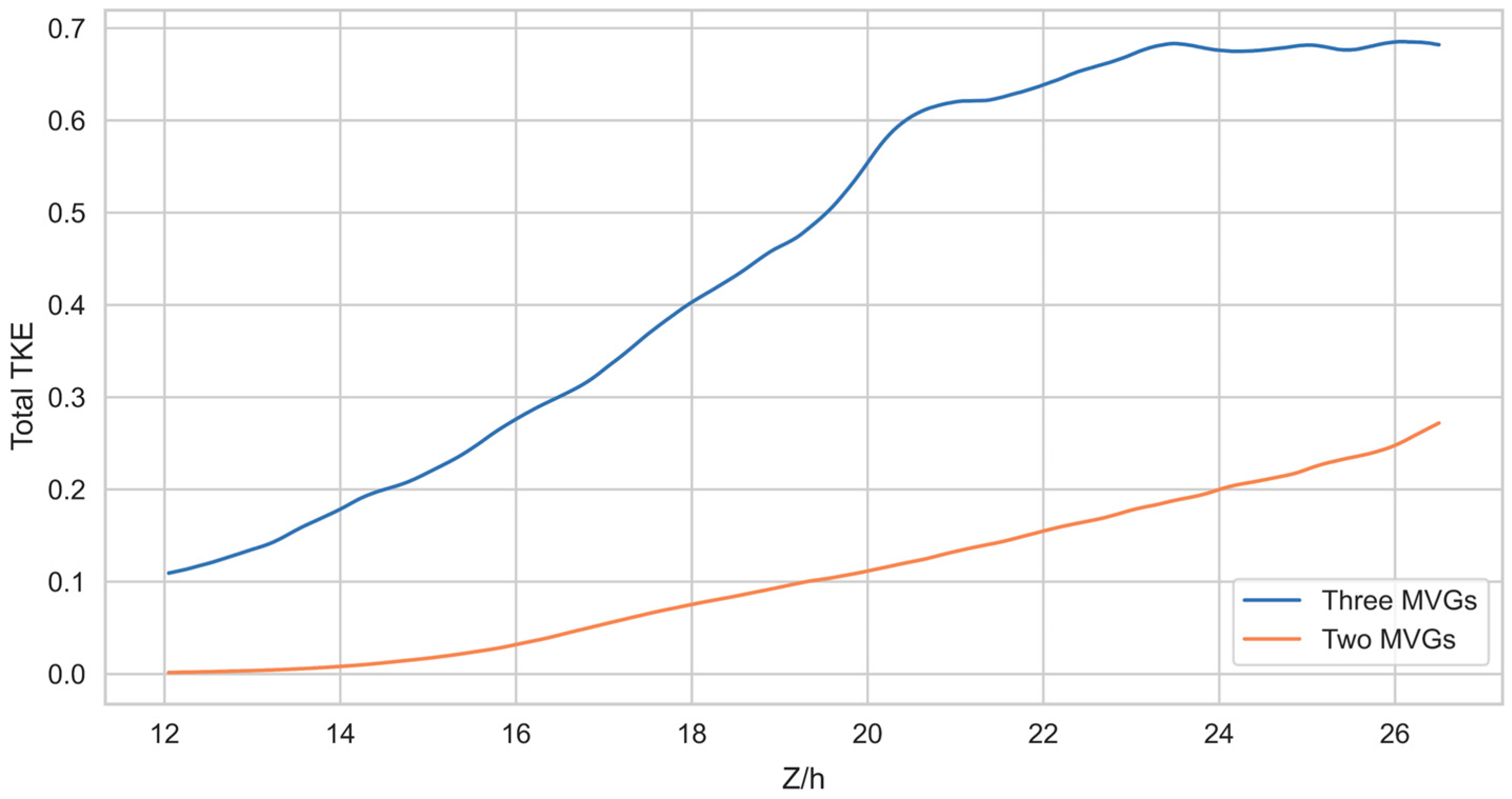
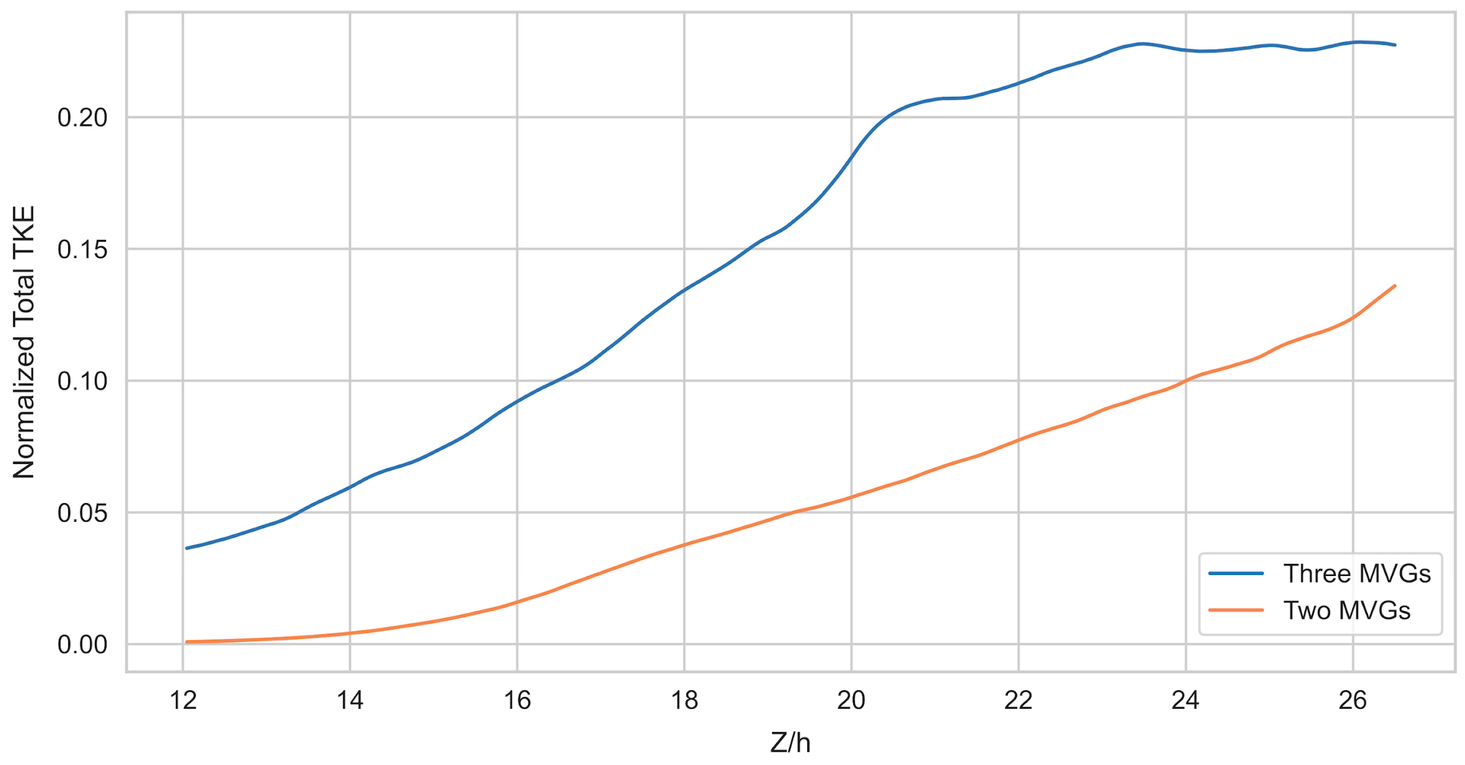
Figure 13 illustrates the total TKE distribution along the streamwise direction, confirming that in the two-MVG case, TKE continues to increase with greater distance from the MVGs, while in the three-MVG case, it rises to a peak and then enters a plateau phase. To account for the differing number of MVGs and isolate their individual contributions, Figure 14 presents the normalized total TKE, calculated by dividing the total TKE by the number of MVGs in each case. This normalization reveals that the TKE generated per MVG in the three-MVG case exceeds that in the two-MVG case, indicating enhanced effectiveness of the three-MVG configuration in energizing the boundary layer.

3.3. Vortex Structures

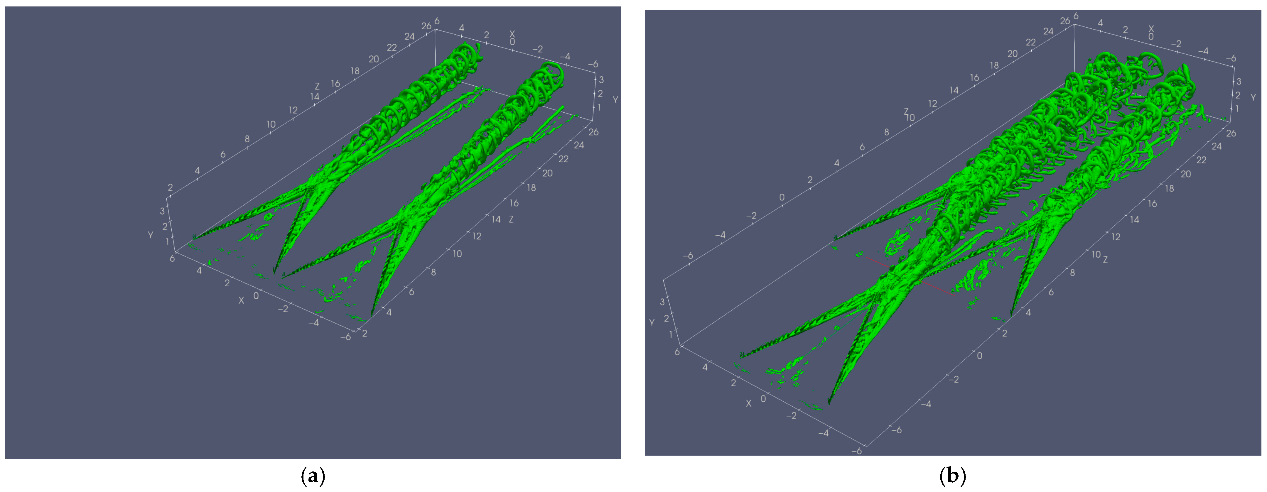
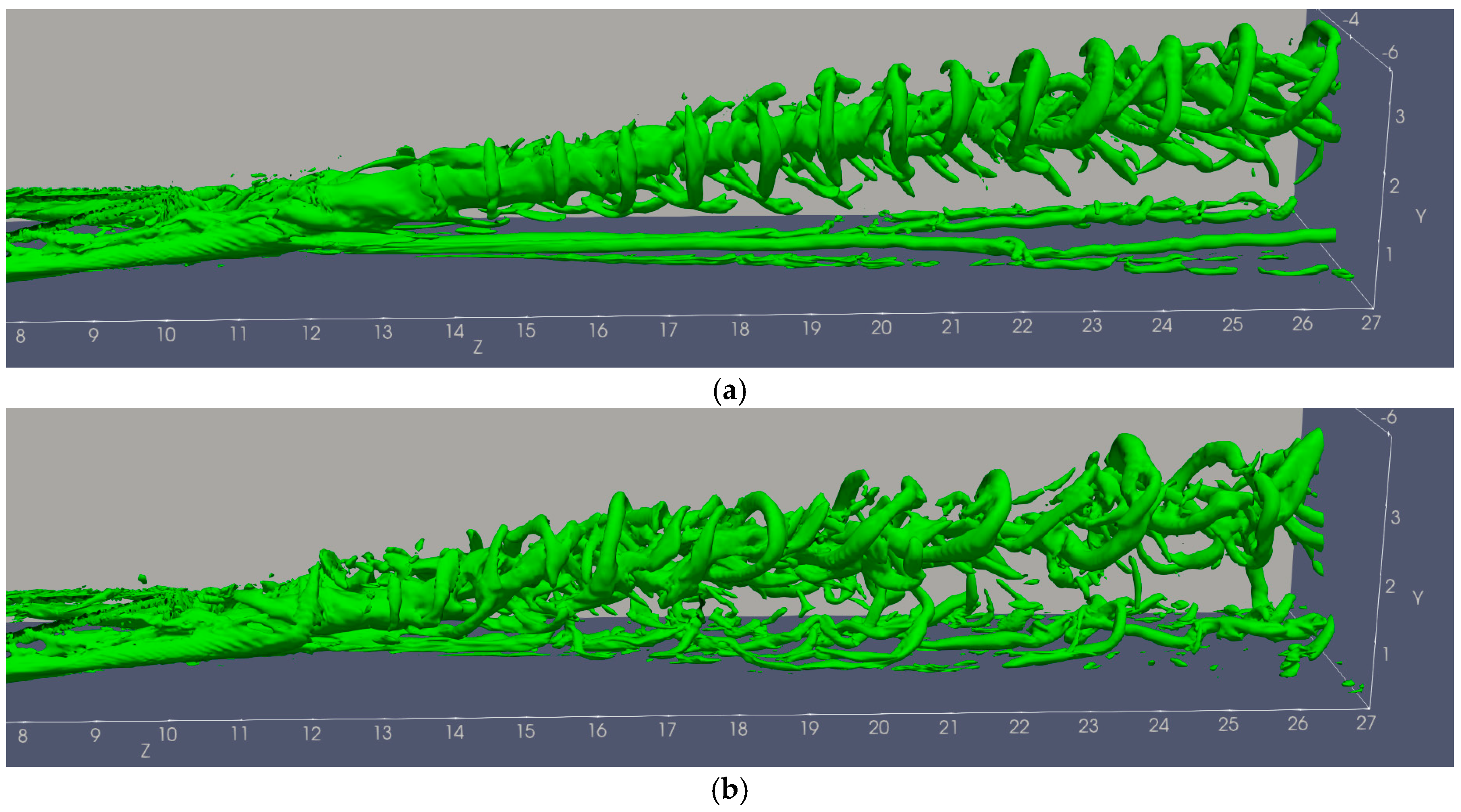
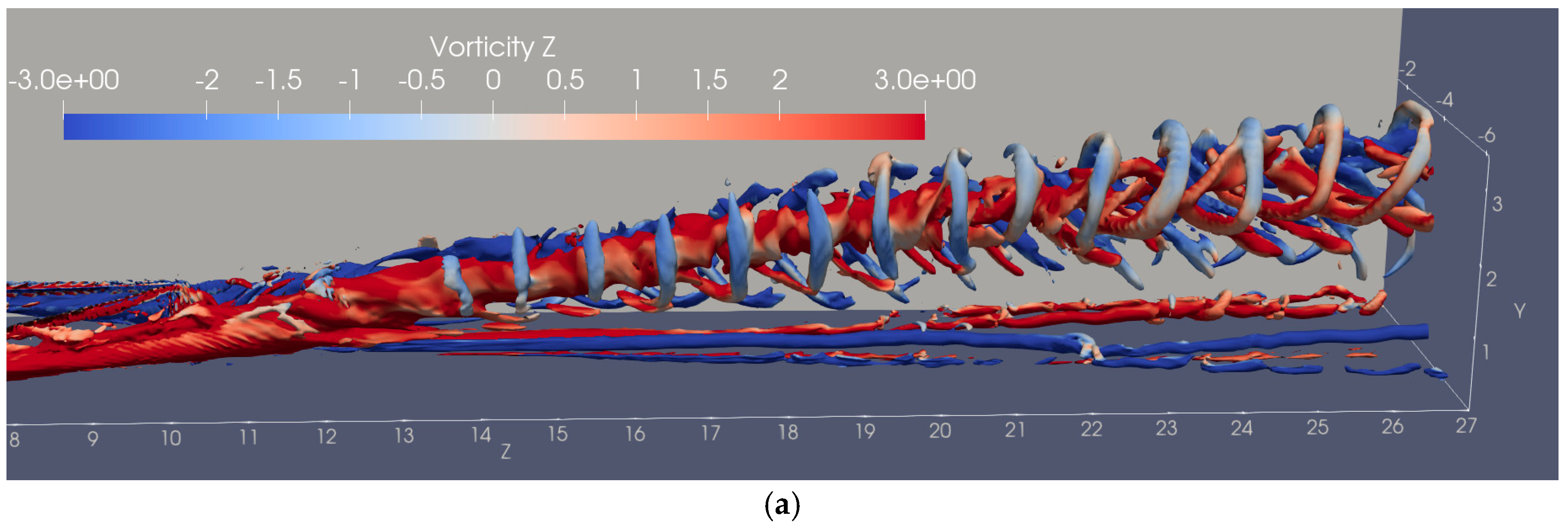
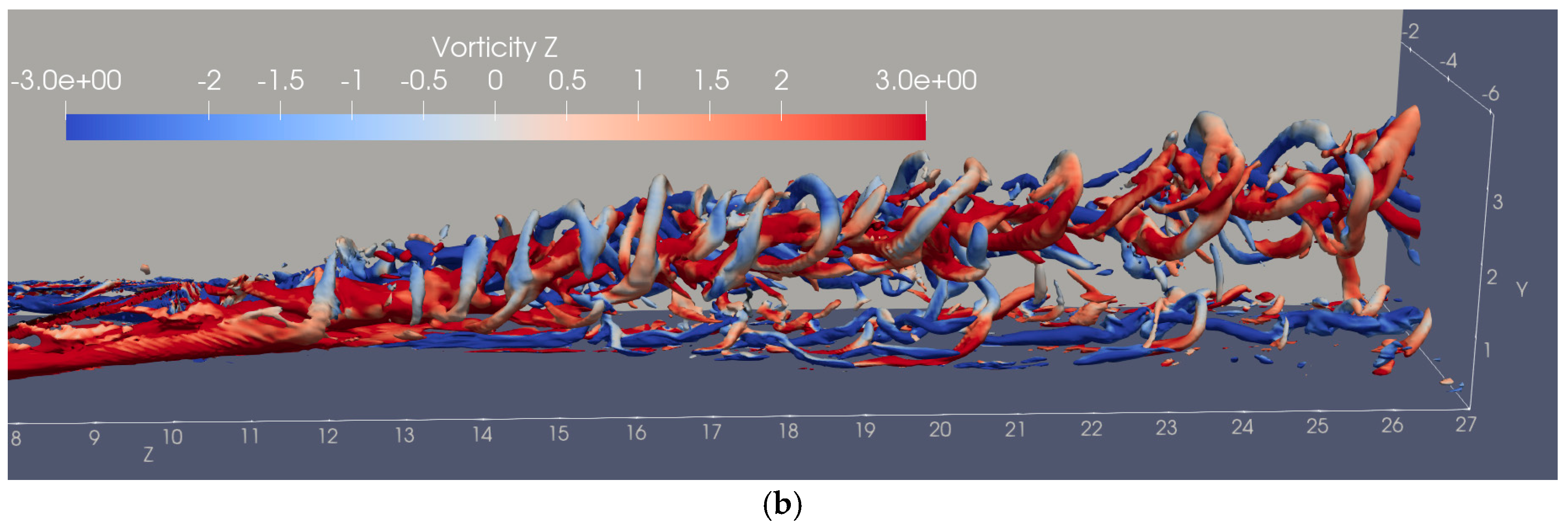
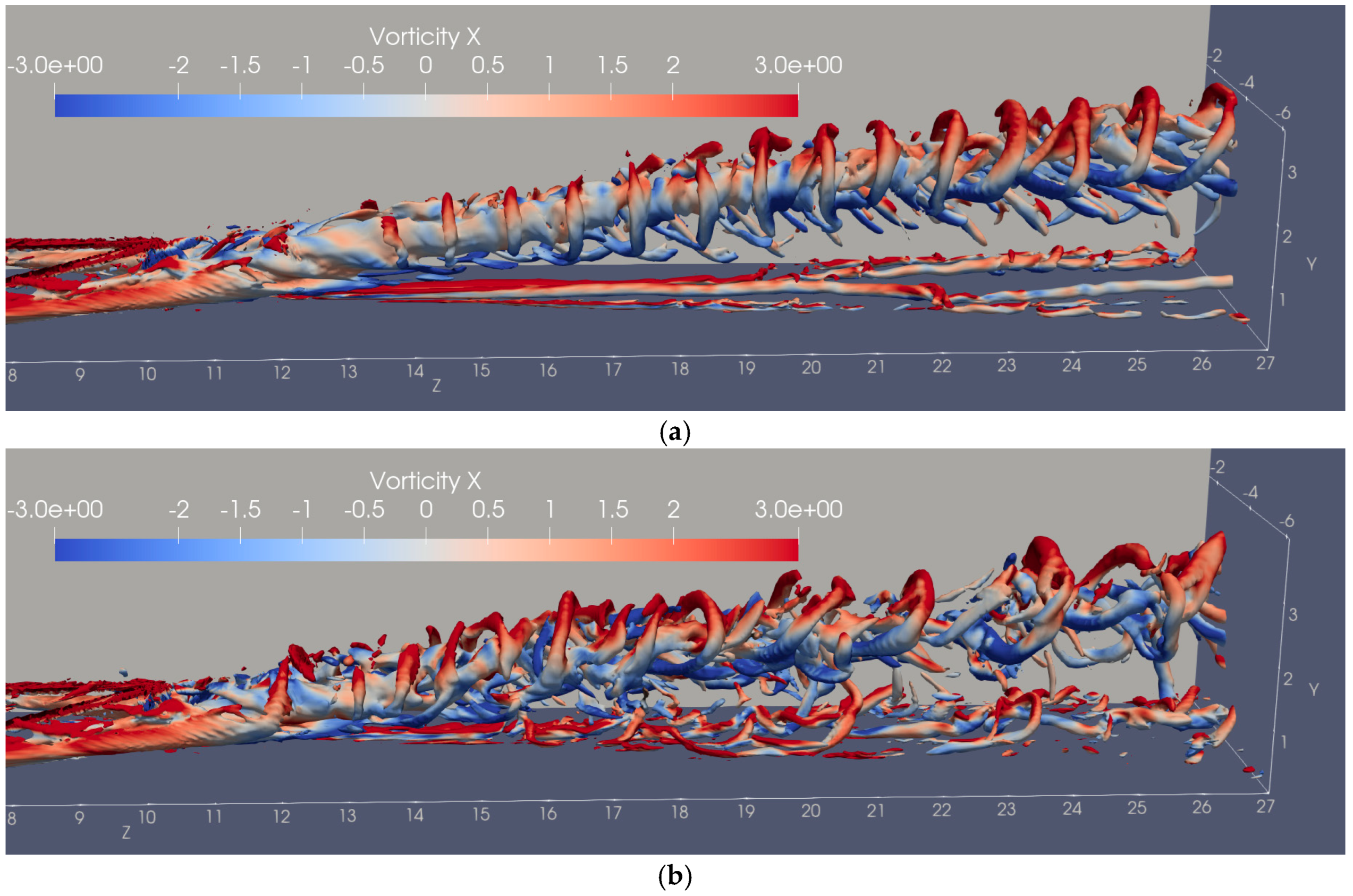
To explore the complex instantaneous vortex structures induced by micro-vortex generators (MVGs), Figure 15 employs Liutex iso-surfaces at R = 0.7 to identify vortices in both the two-MVG and three-MVG cases. The results align with those from the time-averaged fields, revealing that the two-MVG case exhibits more regular and orderly vortex structures, whereas the three-MVG case displays visible interactions, driven by the vortex rings from the third MVG intersecting with those from the MVGs downstream. To assess the impact of the third MVG on the original vortex structures of the downstream MVGs, Figure 16 provides a detailed view of the vortex rings generated by the right MVG in both cases. In the two-MVG case, these vortex rings are uniformly arranged, accompanied by several small streamwise vortex tubes near the wall, which, despite some downstream breakup, retain an overall coherent streamwise shape. In contrast, the three-MVG case shows vortex rings that become increasingly chaotic and sparse as they propagate downstream, with the near-wall induced vortices exhibiting greater turbulence and distinct hairpin-like formations. To further observe these differences, Figure 17 and Figure 18 provide the streamwise and spanwise vorticity components, respectively, for the vortices in Figure 16. A notable finding is that the three-MVG case shows a higher frequency of hairpin vortex formation near the wall, suggesting increased three-dimensional turbulence, while the two-MVG case maintains a more two-dimensional flow pattern, indicating less vertical mixing.

4. Conclusions

This study has conducted a comprehensive computational analysis of two MVG array configurations—the two-MVG and the three-MVG—within a supersonic boundary layer at Mach 2.5, utilizing LES. The investigation, centered on mean flow vortex structures, vorticity distributions, momentum boundary layer thickness, and turbulent kinetic energy, reveals distinct flow characteristics influenced by the MVG array arrangements. In the two-MVG case, although the two MVGs are placed next to each other, it still generates symmetric and regular vortex pairs with minimal interaction, resulting in a steady increase in TKE and a thicker momentum boundary layer, indicative of significant energy loss. In contrast, the three-MVG case, with an additional downstream MVG, introduces complex vortex interactions that distort and fragment the primary vortices, enhancing TKE magnitude and rapid expansion of turbulent regions. This configuration reduces energy loss from the downstream MVGs, as evidenced by a thinner momentum boundary layer, and exhibits a peak TKE that slightly declines downstream, suggesting a balance between mixing enhancement and dissipation. Instantaneous vortex analysis further highlights the three-MVG case’s chaotic, hairpin-dominated structures near the wall, contrasting with the orderly streamwise vortices of the two-MVG case, pointing to increased three-dimensional turbulence. Collectively, these findings demonstrate that the three-MVG configuration offers superior boundary layer energization and mixing potential, albeit with added complexity and potential energy dissipation, compared to the two-MVG case. Future research may explore optimal MVG spacing and placement to maximize flow control efficacy while minimizing energy losses, potentially with comparisons to other MVG configurations.

Author Contributions

Conceptualization and methodology, C.C., Y.Y. (Yong Yang) and Y.Y. (Yonghua Yan); formal analysis, C.C., Y.Y. (Yong Yang) and Y.Y. (Yonghua Yan); writing—original draft preparation, Y.Y. (Yong Yang) and Y.Y. (Yonghua Yan); writing—review and editing, Y.Y. (Yong Yang), Y.Y. (Yonghua Yan), M.A.S. and C.C.; visualization, Y.Y. (Yong Yang) and M.A.S. All authors have read and agreed to the published version of the manuscript.

Funding

This work relied on computations performed on the WTAMU HPC cluster, which was funded by the National Science Foundation (NSF CC* GROWTH 2018841).

Data Availability Statement

The original contributions presented in this study are included in the article. Further inquiries can be directed to the corresponding author.

Acknowledgments

This research is supported by the Mississippi NASA EPSCoR program.

Conflicts of Interest

The authors declare no conflicts of interest.

Abbreviations

The following abbreviations are used in this manuscript:
DNSDirect Numerical Simulation
LESLarge Eddy Simulation
MVGMicro-Vortex Generator
SBLIShock-Wave Boundary Layer Interaction
TVDTotal Variation Diminishing
WENOWeighted Essentially Non-Oscillatory
TKETurbulent Kinetic Energy

References

  1. Délery, J.; Dussauge, J.P. Some physical aspects of shock wave/boundary layer interactions. Shock Waves 2009, 19, 453–468. [Google Scholar] [CrossRef]
  2. Babinsky, H.; Li, Y.; Pitt Ford, C.W. Microramp Control of Supersonic Oblique Shock-Wave/Boundary-Layer Interactions. AIAA J. 2009, 47, 668–675. [Google Scholar] [CrossRef]
  3. Sun, Z.; Scarano, F.; van Oudheusden, B.W.; Schrijer, F.F.J.; Yan, Y.; Liu, C. Numerical and Experimental Investigations of the Supersonic Microramp Wake. AIAA J. 2014, 52, 1518–1527. [Google Scholar] [CrossRef]
  4. Wang, B.; Liu, W.; Zhao, Y.; Fan, X.; Wang, C. Experimental Investigation of the Micro-Ramp Based Shock Wave and Turbulent Boundary Layer Interaction Control. Phys. Fluids 2012, 24, 055110. [Google Scholar] [CrossRef]
  5. Zhang, B.; Zhao, Q.; Xiang, X.; Xu, J. An Improved Micro-Vortex Generator in Supersonic Flows. Aerosp. Sci. Technol. 2015, 47, 210–215. [Google Scholar] [CrossRef]
  6. Liu, J.; Khine, Y.Y.; Saleem, M.; Lopez Rodriguez, O.; Gutmark, E. Supersonic Jet Noise Reduction Using Micro Vortex Generators. In Proceedings of the AIAA AVIATION 2021 FORUM, Virtual Event, 2–6 August 2021; American Institute of Aeronautics and Astronautics: Reston, VA, USA, 2021. [Google Scholar]
  7. Xue, D.; Chen, Z.; Jiang, X.; Fan, B. Numerical Investigations on the Wake Structures of Micro-Ramp and Micro-Vanes. Fluid Dyn. Res. 2014, 46, 015505. [Google Scholar] [CrossRef]
  8. Wang, B.; Liu, W.D.; Sun, M.B.; Zhao, Y.X. Fluid Redistribution in the Turbulent Boundary Layer Under the Microramp Control. AIAA J. 2015, 53, 3777–3787. [Google Scholar] [CrossRef]
  9. Yan, Y.; Chen, L.; Li, Q.; Liu, C. Numerical Study of Micro-Ramp Vortex Generator for Supersonic Ramp Flow Control at Mach 2.5. Shock Waves 2017, 27, 79–96. [Google Scholar] [CrossRef]
  10. Nishantt, N.; Baraiya, N.A. Flow Control Using MVG in Shock Wave/Boundary Layer Interaction. In Recent Advances in Fluid Dynamics; Banerjee, J., Shah, R.D., Agarwal, R.K., Mitra, S., Eds.; Lecture Notes in Mechanical Engineering; Springer Nature: Singapore, 2023; pp. 175–190. ISBN 978-981-19-3378-3. [Google Scholar]
  11. Saleem, M.; Karnam, A.; Rodriguez, O.; Liu, J.; Gutmark, E. Flow and Acoustic Fields Investigation of Noise Reduction by Micro Vortex Generators in Supersonic Nozzles. Phys. Fluids 2023, 35, 106111. [Google Scholar] [CrossRef]
  12. Lu, F.; Pierce, A.; Shih, Y. Experimental Study of near Wake of Micro Vortex Generators in Supersonic Flow. In Proceedings of the 40th Fluid Dynamics Conference and Exhibit, Chicago, IL, USA, 28 June–1 July 2010; American Institute of Aeronautics and Astronautics: Reston, VA, USA, 2010. [Google Scholar]
  13. Reddy, H.S.B. Optimum micro-vortex generator design for planar symmetric diffuser under fully developed turbulent flow. Phys. Fluids 2024, 36, 125160. [Google Scholar] [CrossRef]
  14. Chen, C.; Yang, Y.; Yan, Y. Computational Analysis of Tandem Micro-Vortex Generators for Supersonic Boundary Layer Flow Control. Computation 2025, 13, 101. [Google Scholar] [CrossRef]
  15. Jiang, G.-S.; Shu, C.-W. Efficient Implementation of Weighted ENO Schemes. J. Comput. Phys. 1996, 126, 202–228. [Google Scholar] [CrossRef]
  16. Liu, C.; Gao, Y.; Tian, S.; Dong, X. Rortex—A New Vortex Vector Definition and Vorticity Tensor and Vector Decompositions. Phys. Fluids 2018, 30, 035103. [Google Scholar] [CrossRef]
  17. LarKermani, E.; Roohi, E.; Porté-Agel, F. Evaluating the Modulated Gradient Model in Large Eddy Simulation of Channel Flow with OpenFOAM. J. Turbul. 2018, 19, 600–620. [Google Scholar] [CrossRef]
  18. Zahiri, A.-P.; Roohi, E. Anisotropic Minimum-Dissipation (AMD) Subgrid-Scale Model Implemented in OpenFOAM: Verification and Assessment in Single-Phase and Multi-Phase Flows. Comput. Fluids 2019, 180, 190–205. [Google Scholar] [CrossRef]
Figure 1. Configuration of the two-MVG case: (a) The wall of the whole simulation domain; (b) Top view of MVGs configuration.
Processes 13 02818 g001
Figure 2. Configuration of the three-MVG case: (a) The wall of the whole simulation domain; (b) Top view of MVGs configuration.
Processes 13 02818 g002
Figure 3. Configuration of a single MVG.
Processes 13 02818 g003
Figure 4. Vortex structures generated by MVGs in time-averaged fields: (a) Two-MVG case; (b) Three-MVG case. The green surfaces are Liutex iso-surface at R = 0.3 .
Processes 13 02818 g004
Figure 5. An XY plane positioned at Z = 18h in the three-MVG case, where h is the MVG height.
Processes 13 02818 g005
Figure 6. The distribution of streamwise vorticity on Z = 18h plane: (a) two-MVG case; (b) three-MVG case.
Processes 13 02818 g006
Figure 7. The streamlines on Z = 18h plane: (a) two-MVG case; (b) three-MVG case.
Processes 13 02818 g007
Figure 8. Three blocks in three-MVG case. The left block is from x = 2h to x = 4h, center from x = −h to x = h, right from x = −4h to x = −2h.
Processes 13 02818 g008
Figure 9. Momentum boundary layer thickness downstream of MVGs. Solid lines indicate the three-MVG case, while dashed lines denote the two-MVG case. Blue lines represent the momentum thickness behind the center MVG, green lines the left MVG, and orange lines the right MVG.
Processes 13 02818 g009
Figure 10. XY planes displaying the TKE distribution along the streamwise direction in the three-MVG case, located at Z = 14h, 17h, 20h, 23h, and 26h, respectively.
Processes 13 02818 g010
Figure 11. TKE distribution on the planes in the two-MVG case, located at (a) z = 14h; (b) z = 17h; (c) z = 20h; (d) z = 23h; (e) z = 26h.
Processes 13 02818 g011aProcesses 13 02818 g011b
Figure 12. TKE distribution on the planes in the three-MVG case, located at (a) z = 14h; (b) z = 17h; (c) z = 20h; (d) z = 23h; (e) z = 26h.
Processes 13 02818 g012aProcesses 13 02818 g012b
Figure 13. Total TKE distribution along streamwise direction.
Processes 13 02818 g013
Figure 14. Normalized total TKE along streamwise direction.
Processes 13 02818 g014
Figure 15. Instant vortex structures generated by MVGs: (a) two-MVG case; (b) three-MVG case. The green surfaces are Liutex iso-surface at R = 0.7 .
Processes 13 02818 g015
Figure 16. Detailed view of the vortex rings generated by the right MVG in both cases: (a) two-MVG case; (b) three-MVG case.
Processes 13 02818 g016
Figure 17. Streamwise (Z direction) component of vorticity of the vortices generated by the right MVG in both cases: (a) two-MVG case; (b) three-MVG case.
Processes 13 02818 g017aProcesses 13 02818 g017b
Figure 18. Spanwise (X direction) component of vorticity of the vortices generated by the right MVG in both cases: (a) two-MVG case; (b) three-MVG case.
Processes 13 02818 g018
Disclaimer/Publisher’s Note: The statements, opinions and data contained in all publications are solely those of the individual author(s) and contributor(s) and not of MDPI and/or the editor(s). MDPI and/or the editor(s) disclaim responsibility for any injury to people or property resulting from any ideas, methods, instructions or products referred to in the content.