1. Introduction
Much research on renewable energy sources is being developed currently, and one of the promising alternatives is ethanol, which stands out due to its biological and renewable origin [
1,
2]. Ethanol—a biofuel—results from the fermentation of natural sugars, requiring raw materials such as sugar cane or non-food waste with high availability [
3,
4].
Chemical reactions and microorganism activities needed for ethanol production are carried out in bioreactors. The design of the bioreactor and the processes adopted must provide optimal conditions for ethanol production [
5].
The yeast Saccharomyces cerevisiae is typically used for ethanol production in bioreactors, as it is easy to handle and its biomass can be reused [
6,
7]. In the fermentation process, the temperature of the bioreactor is a crucial factor, as it influences the fermentation and the denaturation process of microorganisms’ proteins [
3,
8]. In addition to temperature, pressure, pH, and dissolved oxygen concentration influence the growth of microorganisms during fermentation. To optimize the process, controlling these variables is a relevant alternative, considering that the growth rate of microorganisms directly impacts the quality and quantity of ethanol [
9].
We can observe in the literature several approaches for control applied to bioreactors. A proposal for temperature control is presented in [
10], considering the fuzzy-PI and fuzzy-PID controller strategies in the control design. Numerical results demonstrated that the fuzzy-PI controller reduces approximately 84.5% in control effort and 6.75% in total utility demand compared to a conventional PI controller.
Temperature control was also presented in [
11,
12], considering state-dependent Riccati equation (SDRE) and linear quadratic regulator (LQR) controls, respectively, with the focus in both cases on thermal variation in the reactor and jacket. Numerical results demonstrated were considered to evidence the effectiveness of the proposed controls in managing the internal temperature of the bioreactor with the control of the flow of the coolant in the bioreactor jacket.
In [
13], the temperature control of a transesterification reactor is proposed, considering neuro-fuzzy techniques with metaheuristic adjustment. Numerical results demonstrate that neuro-fuzzy control has proven to be more effective than classical PID control.
In [
14], the temperature control of a bioreactor is considered. The control design considered using a fractional-order PID controller as a local controller, and its parameters are adjusted with a genetic algorithm. A fuzzy gain scaling scheme based on the Tagaki–Sugeno fuzzy model is used to interpolate the outputs of the FOPID control. Numerical results demonstrate the proposed control’s effectiveness compared with an adaptive nonlinear controller.
In [
15], a fuzzy logic controller was designed for temperature control of a bioreactor, and its effectiveness was compared with that of conventional PI and PID controllers through numerical simulations. In [
16], temperature control of a non-isothermal CSTR process was carried out with a fuzzy logic controller, and its effectiveness was compared with that of a PID controller through numerical simulations.
Using optimal linearized controls has proven to be an effective alternative in the control applied in bioreactors. In [
17,
18,
19], the LQR control was successfully used for the linearized bioreactor model. The simulation results demonstrated that the LQR controller strategy efficiently regulates the desired product concentration and the cooling jacket temperature.
In this work, we seek to contribute to the body of knowledge on temperature control of bioreactors, considering the model proposed by [
3,
8] and later used by [
11,
12]. First, we propose controlling the internal temperature of the bioreactor by adjusting the flow of the cooling liquid applied to the bioreactor jacket. A linear feedback control was obtained from the linearization of the system state matrix, considering a constant temperature of the water entering the reactor to control the liquid flow. A sinusoidal variation of the temperature is considered to annualize the robustness of the control to variations in the temperature of the water entering the bioreactor.
In addition to controlling the cooling liquid flow, the temperature of the water entering the bioreactor is controlled using the SDRE (state-dependent Riccati equation) control. With the two control projects designed and working efficiently, they are converted into Tagaki–Sugeno neuro-fuzzy controllers with constant gains, thus enabling the obtaining of optimal control signals, with the advantages of propositional fuzzy controllers, such as being more robust to uncertainties in the sensors or the input variables, since they interpolate the controller outputs.
The structure of the paper is as follows. In
Section 2, the modeling of the nonlinear bioreactor is presented, and its dynamic behavior under control is presented. In
Section 3, the control of the reactor temperature is proposed, considering the variation of the reactor inlet temperature, and an equivalent fuzzy control is additionally included utilizing a neuro-fuzzy.
Section 4 proposes an SDRE control to control the reactor inlet temperature, including a neuro-fuzzy equivalent fuzzy control. Finally,
Section 5 concludes the paper.
2. Mathematical Model
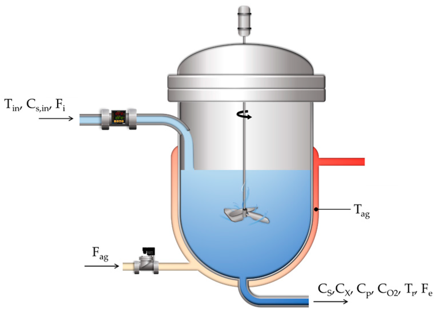
We can see in
Figure 1 a representation of a continuous fermentation bioreactor, containing the cooling jacket, and an actuator used to control the internal temperature of the bioreactor.
The mathematical model that represents the dynamics of the system represented by
Figure 1 is given by [
3,
8,
12]:
To obtain the mathematical model (Equation (1)), it was considered that the growth of microorganisms in the bioreactor depends on the yeast growth rate and the concentration of microorganisms at the outlet, the mass and energy balance equations, and the influence of temperature, oxygen, and yeast concentrations [Pachauri, a b, Tusset].
CO2,
Cs,
Cx, and
Cp are the concentrations of oxygen, glucose, biomass, and ethanol.
Tag,
Tin, and Tr are the temperatures in the jacket, reactor inlet, and inside the reactor.
Fag is the coolant flow,
Fi is the fermentation vessel inlet flow, and
Fe is the fermenter outlet flow, and
is the jacket volume [
3,
8,
12].
Equation (1) depends on specific parameters, some of which vary over time and as the states of the system [
3,
8,
12]:
Numerical Simulations for the Uncontrolled System
For numerical simulations it will be considered, fourth order Runge–Kutta method, with integration step (h = 0.01), and parameters [
3,
12]:
A1 = 9.5 × 10⁸,
A2 = 2.55 × 1033,
AT = 1,
Fi = 51 [L/h],
Fe = 51 [L/h],
Cheat,ag = 4.18 [Jg
−1 K
−1],
Cheat,r = 4.18 [Jg
−1 K
−1],
Ea1 = 55,000 [J/mol],
Ea2 = 220,000 [J/mol],
kla0 = 38 [h
−1],
Ks = 1.03 [g/L],
Ks1 = 1.68 [g/L],
KT = 3.6 × 10
5 [J h
−1m
−2K
−1],
R = 8.31 [Jmol
−1K
−1],
RSP = 0.435,
Rsx = 0.607,
HCa = −0.303,
HCl = 0.844,
HCO3 = 0.485,
HH = −0.774,
HMg = −0.314,
HNa = −0.550,
HOH = 0.941,
mCaCO3 = 100 [g],
mMgCl2 = 100 [g],
mNaCl = 500 [g],
MCa = 40 [g/mol],
MCaCO3 = 90 [g/mol],
MCl = 35.5 [g/mol],
MCO3 = 60 [g/mol],
YO2 = 0.97,
ΔHr = 518 [kJ/molO
2],
µO2 = 0.5 [h
−1],
µP = 1.79 [h
−1],
ρag = 1000 [g/L] and
ρr = 1080 [g/L]. With initial conditions:
[g/L],
[g/L],
[g/L],
[mg/L],
[°C], and
[°C].
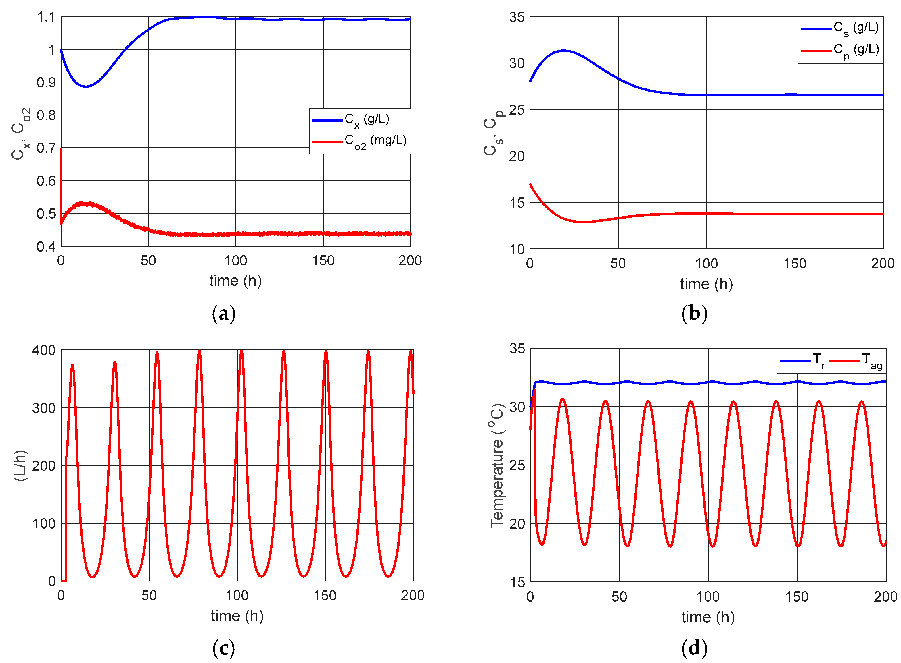
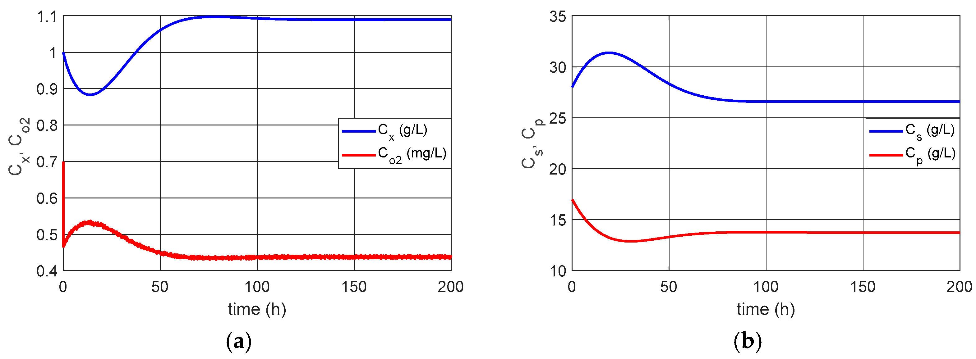
We can observe in the results presented in
Figure 2 that the system stabilized with:
[g/L],
[g/L],
[g/L],
[mg/L],
[°C], and
[°C]. However, according to [
3,
8,
12], the optimum temperature for the alcoholic fermentation of
Saccharomyces cerevisiae is
[°C].
3. Temperature Control with OLFC Control
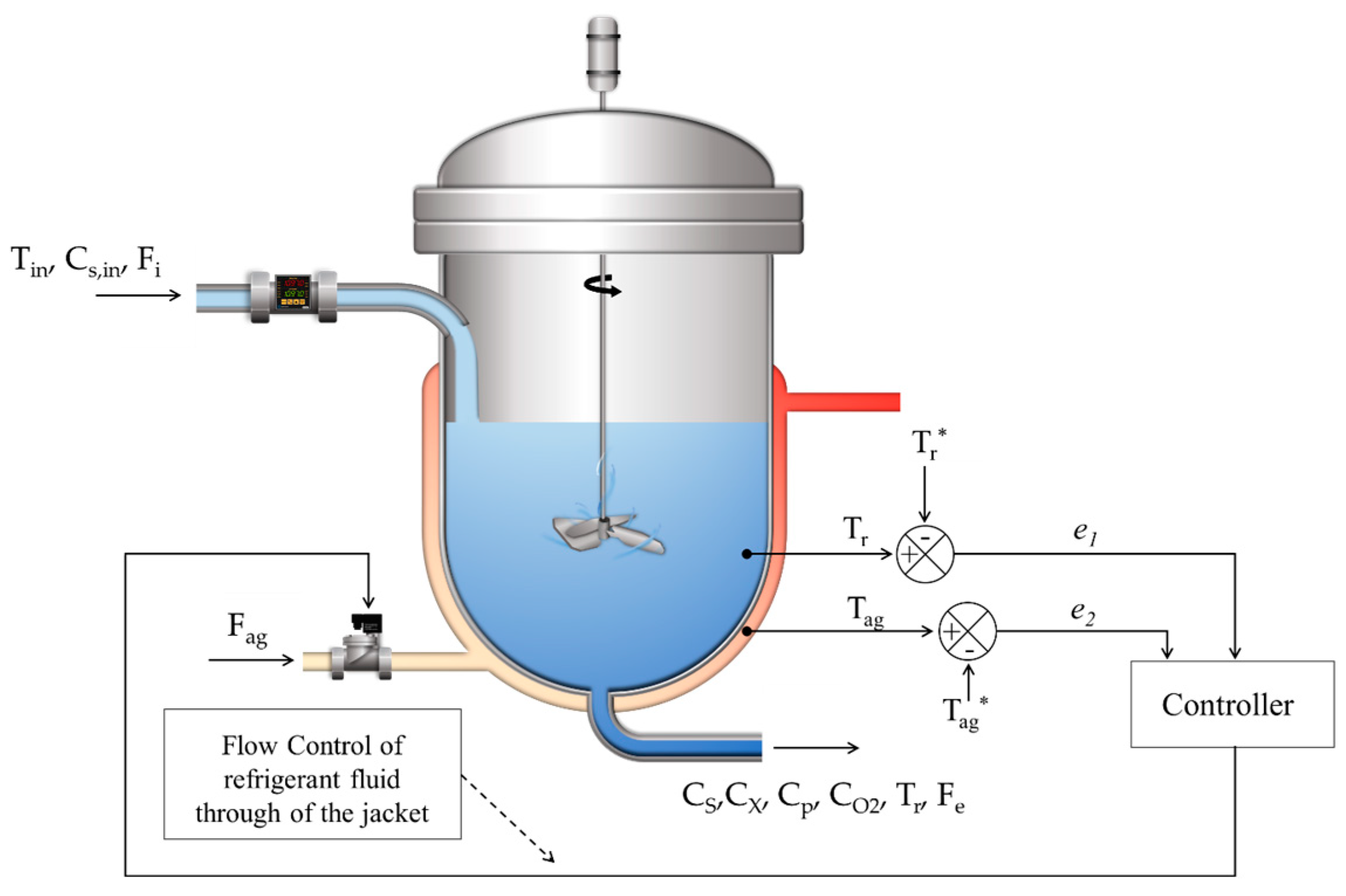
The temperature control of the bioreactor proposed in this paper can be seen in
Figure 3.
The coolant flow in the reactor jacket (
) is controlled to maintain the reactor temperature. Flow control makes it possible to control the internal temperature (
) of the reactor, as shown in
Figure 3.
The system (1) can be presented by the following matrix form:
where
,
,
,
and
.
A is the state matrix, B is the control matrix, G is the matrix of terms that do not depend on the states, U is the control vector, and X is the states. And: , , , , , , , , , , , , , and .
The linear feedback control
U is defined as follows:
where
,
represents the system states and
the desired states. The matrix
is obtained by solving the Riccati equation:
The functional cost for the control problem
U is given by:
where
Q and
R are positive definite matrices.
3.1. Numerical Simulations for the System with OLFC Control
Considering the linearization of matrix
A, considering the method based on the Jacobian matrix of the Taylor series expansion [
20] concerning the desired states:
[g/L],
[g/L],
[g/L],
[mg/L],
[°C] and
[°C], parameters obtained from the system for
°C, the optimum temperature for the alcoholic fermentation of
Saccharomyces cerevisiae.
And defining: and .
Considering
, and:
where
, with
i = 1 and
j = 1:6, are the gains of the control, obtained according to Equation (8).
We can observe that the gains of the matrix
Q give maximum priority to controlling the reactor temperature
Tr, (parameter q
5,5), aiming to control the temperature at its ideal point, because the optimum temperature for the alcoholic fermentation of Saccharomyces cerevisiae is
= 32 °C. Considering matrices
A and
B of system (7), we obtain a controllable system with rank 6 for the controllability matrix:
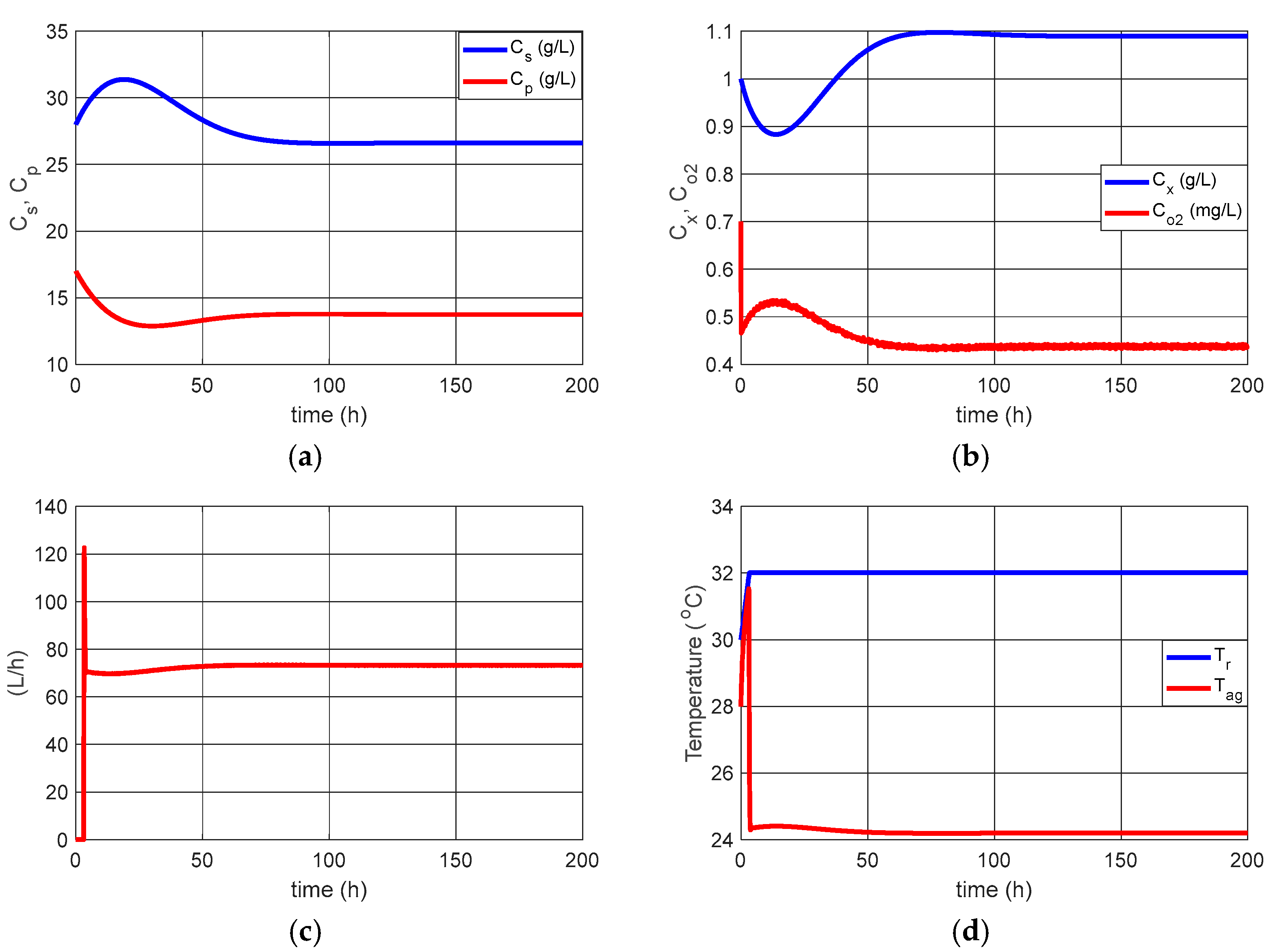
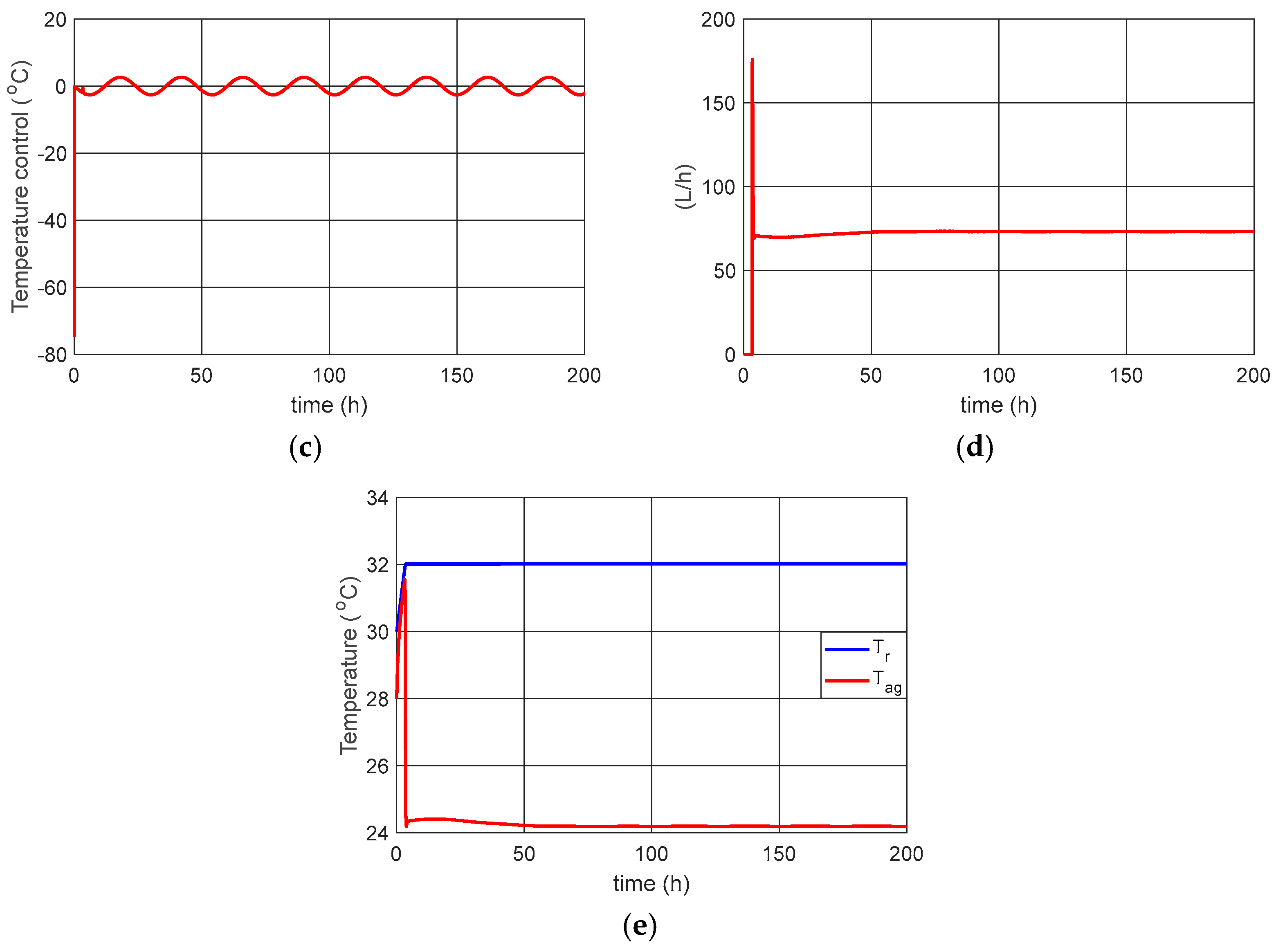
The results of the control of the coolant flow rate variation (Fag) considering the introduction of control (11) in Equation (1) are presented in
Figure 4.
We can see in the results in
Figure 4 that the coolant flow control (
Fag) brought the reactor temperature to the desired 32 °C, as well as the other states to the desired points.
3.2. Proposal for an Equivalent Fuzzy Control
To obtain a fuzzy controller with behavior equivalent to that obtained by the OLFC control, the application of the Matlab neuro-fuzzy tool was considered.
Since the main objective is to control the reactor temperature, and obtaining fuzzy control is to obtain more flexible control for future applications, only the reactor temperature Tr, the jacket temperature Tag, and the refrigerant flow Fag will be considered in obtaining fuzzy control.
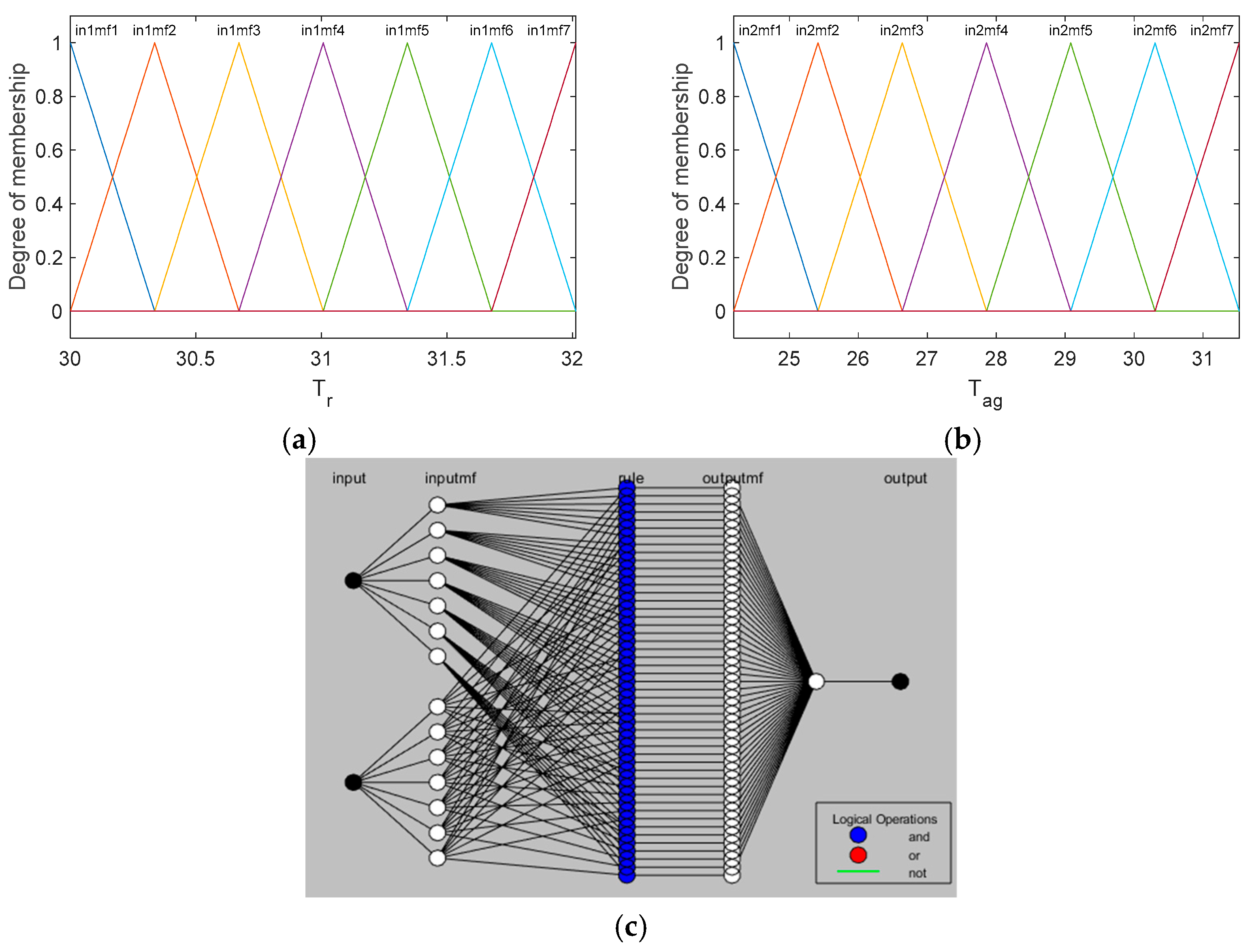
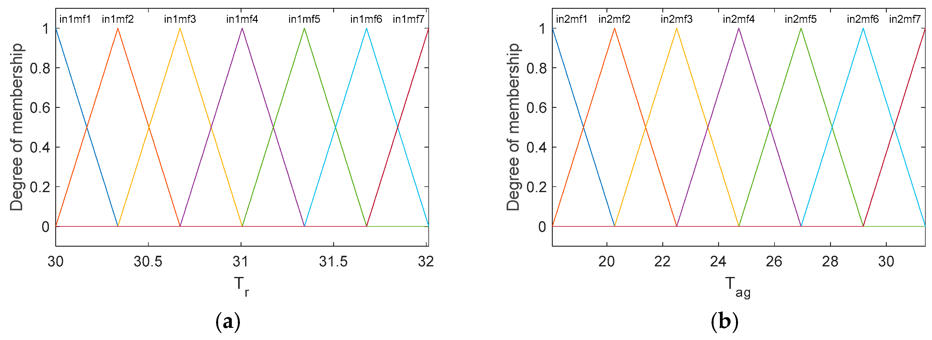
The Tagaki–Sugeno method was considered, with seven membership functions for Tr and seven membership functions for Tag, for the output constant outputs were considered and for the connector rules is considered “AND”, for the training of the neural network an epoch = 1000 was considered, and a hybrid optimization method. The “prod” operator, a product of fuzzified input values, was considered for the AND operator method, which combines fuzzified input values into a fuzzy rule antecedent, and the “probor” operator, a probabilistic OR of fuzzified input values. The “wtaver” method was considered for defuzzification, which is the weighted average of all rule outputs.
The Tagaki–Sugeno fuzzy control approach combines the flexibility of fuzzy logic with the power of local linear models to provide a versatile and adaptable control framework. The Tagaki–Sugeno method is based on the local linearization of nonlinear systems, providing a practical framework for analysis and control [
21,
22,
23].
This paper considers the adaptive neuro-fuzzy inference system (ANFIS), which combines the learning capabilities of neural networks with the assistive features of fuzzy models, automatically adjusting the parameters of membership functions and fuzzy rules based on training data, resulting in more flexible and efficient models [
24,
25]. Between 3 and 7 membership functions are considered in fuzzifications, a quantity typically used as it presents sufficiently relevant results in fuzzifications [
26].
Figure 5 shows the membership functions for the inputs and the scheme of the neural network used for the defuzzification rules.
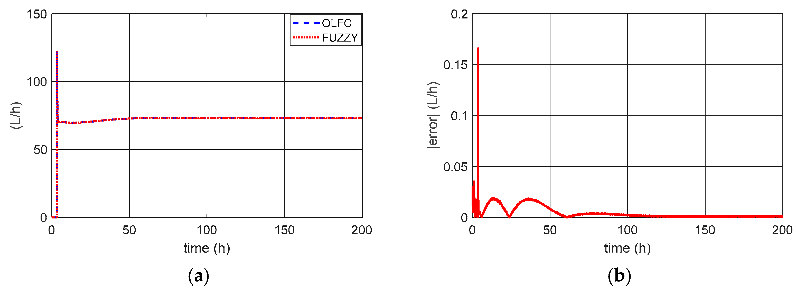
Figure 6 shows the refrigerated fluid flows for OLFC control and fuzzy control, as well as the difference between the two.
Figure 6b shows that the proposed fuzzy control efficiently reproduces the control signal obtained with OLFC control, and the choice of triangular functions in fuzzification was adequate (
Figure 6a). The use of triangular functions is relevant when seeking lower computational costs and applications in embedded or real-time systems.
3.3. Reactor Temperature Control Considering Variations in the Reactor Inlet Temperature
To analyze the influence of variation in the reactor inlet temperature on temperature control, a disturbance in the following form will be considered:
The use of function (13) seeks to represent the variation in ambient temperature during the period of one day, a temperature that the inlet fluid may be subject to.
The results of the control of the coolant flow rate variation (Fag) considering the perturbation in the reactor inlet temperature (Equation (13)) are presented in
Figure 7.
We can observe that even with disturbances in the variation in the reactor inlet temperature, the control is efficient in keeping Tr close to 32 °C, maintaining a maximum error of 5%. However, we see that the system is sensitive to this disturbance, requiring a variation in the flow of coolant according to the variation in the inlet temperature of the reactor “Tin”.
In
Figure 8, we can observe the necessary adjustments in the fuzzy control membership functions for the case with disturbances in the reactor inlet temperature.
Figure 9 shows the refrigerated fluid flows for OLFC control and fuzzy control, as well as the difference between the two, for cases with disturbances in the reactor inlet temperature.
The results in
Figure 9a show that the fuzzy control efficiently generated the control signal obtained with the OLFC control. However, we observed a higher error (
Figure 9b) than that observed for the constant inlet (
Figure 6b) of the reactor inlet temperature.
4. Reactor Inlet Temperature by SDRE
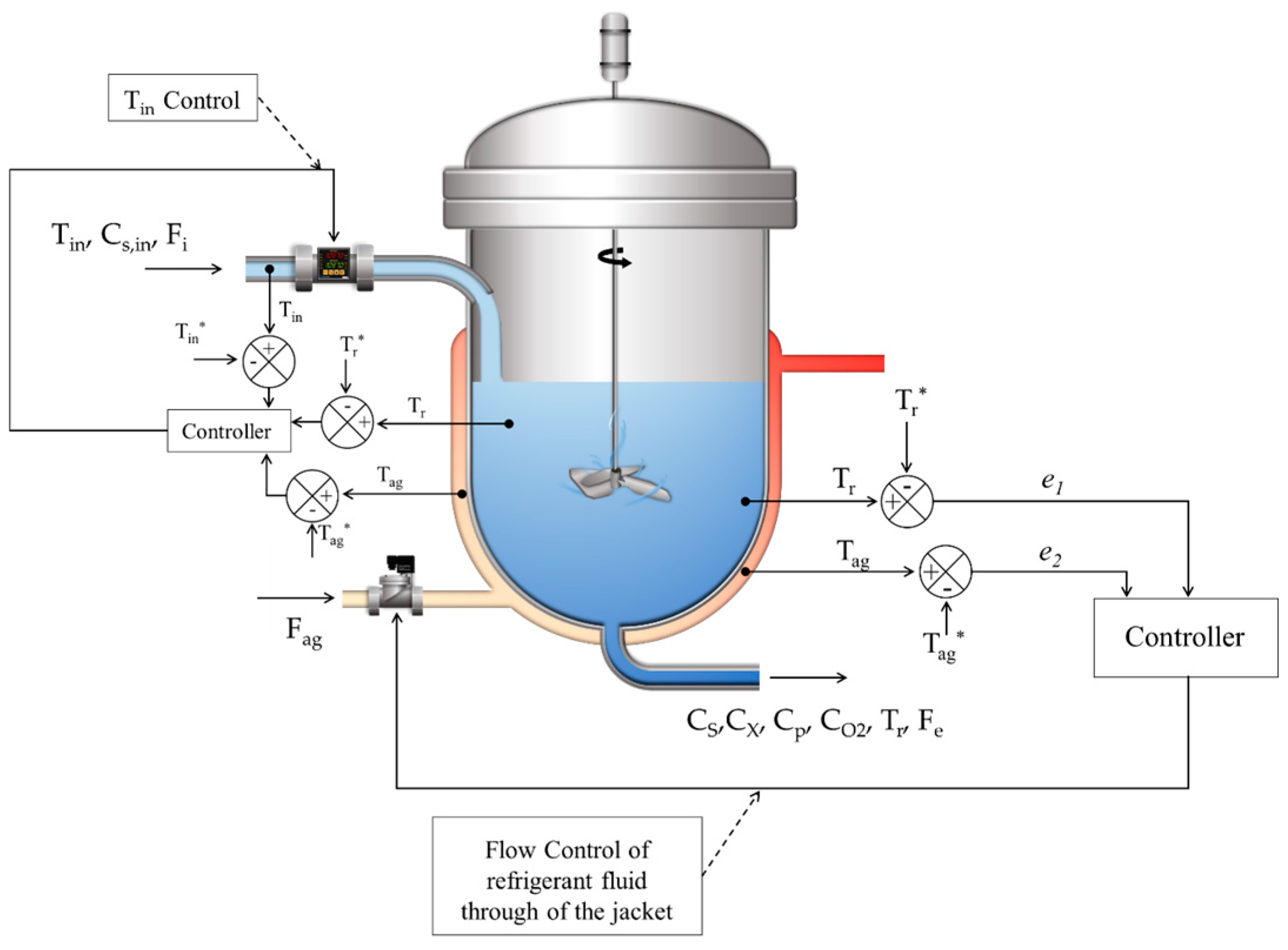
As noted in the previous section, temperature control is sensitive to variations in reactor inlet temperature. To minimize the influence of variations in reactor inlet temperature, this section will consider including a control of this temperature, as illustrated in
Figure 10.
For the practical implementation of the proposed Tin inlet temperature control, this work considers incorporating an electrical resistance heating system and Peltier plate cooling into the inlet system. Including these actuator equations in the system is being considered for future work.
As shown in
Figure 10, the control already proposed using the OLFC control is maintained, and a control of the reactor inlet temperature is added independently.
Considering temperature control as the main objective, since in this case study the temperature
Tr is responsible for the optimum temperature for the alcoholic fermentation of Saccharomyces cerevisiae, which depends on
Tag, we propose to use only the last two equations of Equation (1) and include a new equation with sinusoidal variations of the reactor temperature
Tin. This proposal is similar to that successfully used by [
12], where the remaining equations consider only external disturbances.
As can be seen in Equation (13),
does not depend on the states. One way to include state dependence in control is using SDRE control, which allows for different state matrix configurations. This makes it possible to include in the equation
dependence of states
and
, states that in this work are the critical states to be controlled. This ability to be implemented in a wide range of nonlinear systems, and the possibility of obtaining optimal solutions for control purposes, are among the advantages of the technique SDRE [
27,
28,
29,
30].
The system (14) can be presented by the following matrix form:
where
,
,
,
and
.
Where A is the state matrix and is dependent on the states and , B is the control matrix, G is the matrix of terms that do not depend on the states, U is the control vector and X is the states, while is the control of the coolant flow and obtained with the control proposed in the previous section, and is the proposed control of the reactor inlet temperature.
As can be seen in matrix A, states were included as predicted by the SDRE control technique [
27,
28,
29,
30].
where
, with
i = 1 and
j = 1:3, are the gains of the control, obtained according to Equation (8), and the minimization of the functional (10).
Considering , , and the desired states: , and .
And defining: and .
Considering matrices A and B of system (15), we obtain a controllable system with rank 3 for the controllability matrix:
The results of the control of the coolant flow rate variation (F
ag), and control in the reactor inlet temperature, considering the reactor inlet temperature given by Equation (12), are presented in
Figure 11.
As observed, the proposed SDRE control maintained the constant Tin temperature, enabling better efficiency in controlling the refrigerant flow obtained with the OLFC control.
Proposal for an Equivalent Fuzzy Control
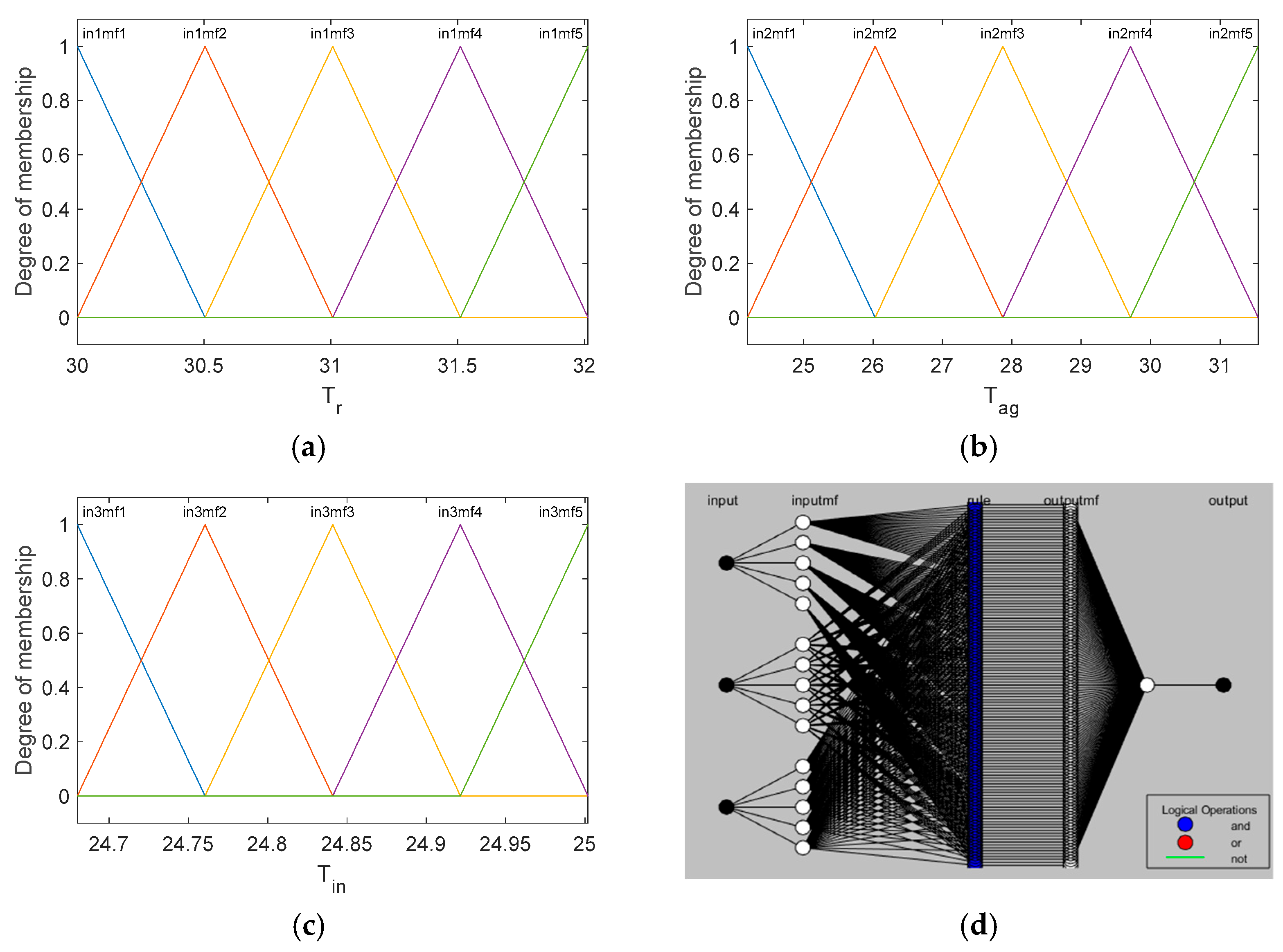
In this case, the Tagaki–Sugeno method should also be considered, with five membership functions for Tr, five membership functions for Tag, and five membership functions for Tin, for the output constant outputs were considered and for the connector rules (and), for the training of the neural network an epchs = 1000 was considered, and a hybrid optimization method.
Figure 12 shows the membership functions for the inputs and the scheme of the neural network used for the defuzzification rules.
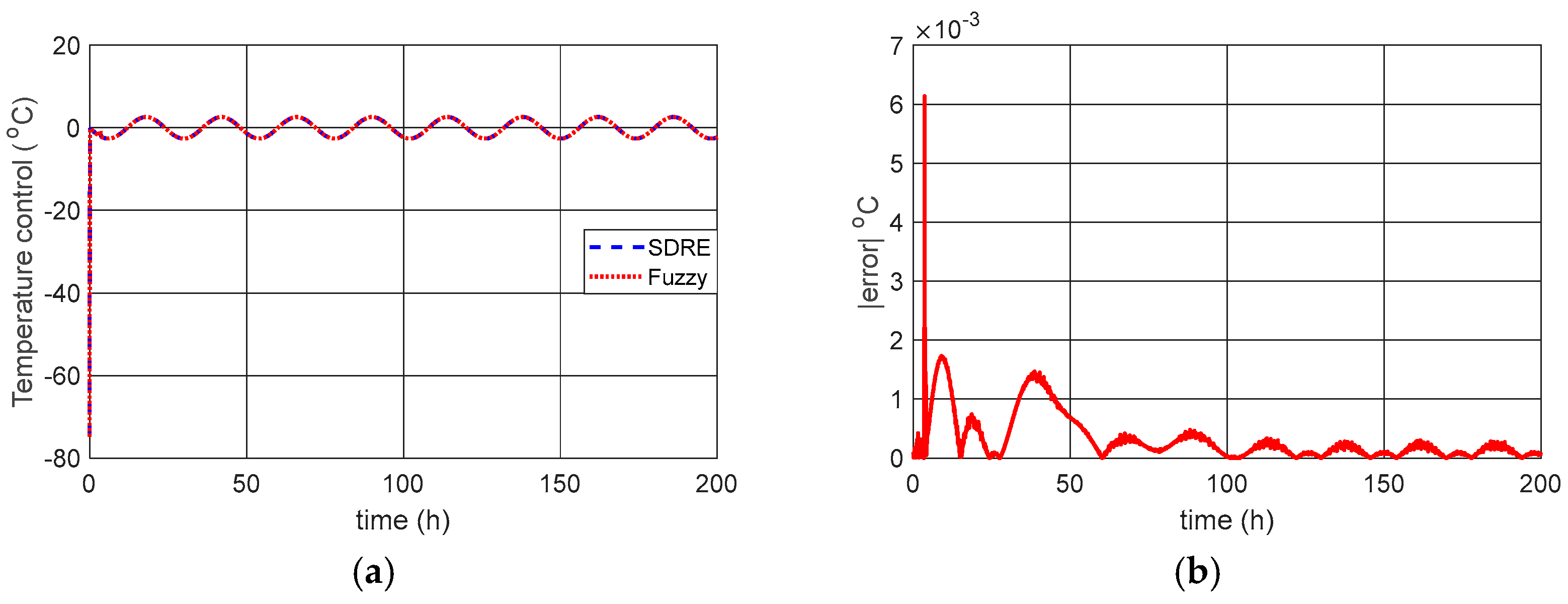
Figure 13 shows the temperature control of the
Tin for SDRE control and fuzzy control, as well as the difference between the two.
The results demonstrate that the equivalent fuzzy control effectively reproduces the control signal obtained with the SDRE control.
5. Conclusions
The results presented demonstrated that it is possible to control the internal temperature of the bioreactor by controlling the flow of coolant that passes through the jacket. We can demonstrate that the proposed linear control effectively controls the coolant flow. In the case of variations in the reactor inlet, it was possible to conclude that controlling only the coolant flow may not be sufficient, requiring a specific control to control the reactor inlet temperature, using an SDRE control.
In comparison with published works with the same bioreactor model, we can highlight the contribution of this article with the control of the reactor temperature by controlling the coolant flow and with the inclusion of the equation that represents the reactor inlet temperature and the control design in comparison with the works presented by [
3,
8]. The results presented in this work demonstrated that the proposed control controlled the system in half the time compared to the PID and fractional order PID controls proposed in [
3,
8], demonstrating the effectiveness of the proposed control compared to the PID control.
Compared to the works [
11,
12], this work contributes by including the equation representing the reactor inlet temperature and the SDRE control for temperature control. Furthermore, the article contributes by including fuzzy controls obtained using neuro-fuzzy.
Future work will consider actuator equations for controlling the reactor inlet temperature and the electrical voltage control required for the control application.
