1. Introduction
The global imperative to decarbonize energy-intensive industries has accelerated the search for efficient and scalable renewable hydrogen production technologies [
1]. Global energy demand has consistently increased in recent years, and it is expected to continue growing in the coming decades. This sustained growth raises concern about global warming and highlights the urgent need to develop improved renewable energy sources.
In the context of the 2050 decarbonization targets, greenhouse gas emissions are expected to be reduced by 80% compared to 1990 levels [
2]. This objective is driving the energy sector toward a transition based on renewable resources and innovative manufacturing approaches. Hydrogen plays a key role in this transition, being widely used across industry as an energy carrier, chemical feedstock, and fuel. Electrolysis technologies currently represent the only viable method for producing green hydrogen at scale.
Among the available water electrolysis technologies, Solid Oxide Electrolysis Cells (SOECs) have emerged as a promising solution due to their high operating temperatures (700–900 °C), which enable higher electrical efficiencies, improved reaction kinetics, and the potential for direct thermal integration with industrial processes [
1]. In contrast, conventional low-temperature electrolysis technologies such as alkaline electrolysis (AEC) and proton exchange membrane electrolysis (PEMEC) are already commercialized but are limited by lower efficiencies and greater sensitivity to electricity costs [
3]. SOECs offer unique advantages, including the ability to co-electrolyze H
2O and CO
2 to produce synthesis gas (syngas) with a tunable H
2/CO ratio, well-suited for downstream applications such as Fischer-Tropsch synthesis and power-to-methane (PtM) conversion [
1,
3]. This flexibility addresses critical limitations in biomass-to-liquid (BtL) processes, where the inherently low H/C ratio in biomass feedstocks has historically constrained carbon efficiencies below 50% [
4].
Recent studies have demonstrated that integrating SOECs with renewable energy sources and advanced thermal energy storage systems can significantly enhance overall process efficiency and economic viability. For example, coupling SOECs with ammonia-based thermochemical energy storage has been shown to achieve solar-to-hydrogen efficiencies up to 26%, outperforming photovoltaic-driven electrolyzer systems by approximately 7% and reducing hydrogen production costs by nearly 19% [
1]. Similarly, the integration of SOECs into continuous and flexible PtM processes, supported by liquid CO
2 energy storage, addresses the operational challenges associated with the intermittency of renewable energy sources. This configuration facilitates real-time production scheduling and reduces safety risks associated with large-scale hydrogen storage [
3]. A further key advantage of SOEC technology is its reversible operation, allowing the same device to operate as a solid oxide fuel cell (SOFC) for electricity generation when needed.
(SOECs) and (SOFCs) share a common electrochemical structure, composed of a dense oxygen-ion-conducting ceramic electrolyte—typically yttria-stabilized zirconia (YSZ)—sandwiched between two porous electrodes [
5]. In SOEC mode, steam (and optionally CO
2) is introduced at the cathode, where it undergoes electrochemical reduction to produce hydrogen (and syngas), while oxygen ions (O
2−) migrate through the electrolyte to the anode, where they release electrons and form O
2 gas [
6]. In SOFC mode, this process operates in reverse: hydrogen or other fuels are oxidized at the anode, generating electrons and oxygen ions that migrate toward the cathode to react with O
2, producing water and electricity [
5,
7]. This reversible operation is a distinctive advantage, enabling flexible use of the same device for either hydrogen production or electricity generation, depending on system needs and energy availability.
Both SOECs and SOFCs exhibit high efficiencies and offer important system-level advantages. SOECs stand out for their superior electrical efficiency, potential for thermal integration with high-temperature industrial processes, and ability to co-electrolyze H
2O and CO
2 to produce syngas with tunable H
2/CO ratios [
1,
3,
6]. However, their operation at 700–900 °C presents challenges related to material degradation, sealing stability, and thermal cycling [
5,
8]. SOFCs offer high fuel flexibility and are well-suited for combined heat and power (CHP) applications, yet they also face drawbacks such as high operating temperatures, extended start-up times, and elevated system costs [
7,
9]. Ongoing research is focused on improving materials stability, reducing system complexity, and enhancing durability under dynamic operating conditions to make both SOEC and SOFC technologies commercially viable at scale.
This review aims to provide a comprehensive assessment of the current state of SOEC integration with industrial processes, highlighting recent technological advancements, innovative process configurations, and techno-economic insights that are shaping the future of renewable hydrogen production.
2. SOEC Process Integration
SOEC can be integrated into a wide range of industrial processes. This section reviews several studies addressing the energy integration of high-temperature electrolysis, structured according to the final product and the type of electrolytic cell employed.
2.1. Hydrogen Production
Most published SOEC studies focus exclusively on hydrogen production, without considering the subsequent synthesis of hydrogen-derived compounds. The integration of SOEC for the renewable production of hydrogen represents a key strategy in supporting the ongoing energy transition.
Zhao et al. [
10] analysed the performance of an SOEC system operating at 800 °C and atmospheric pressure, without incorporating an external heat source.
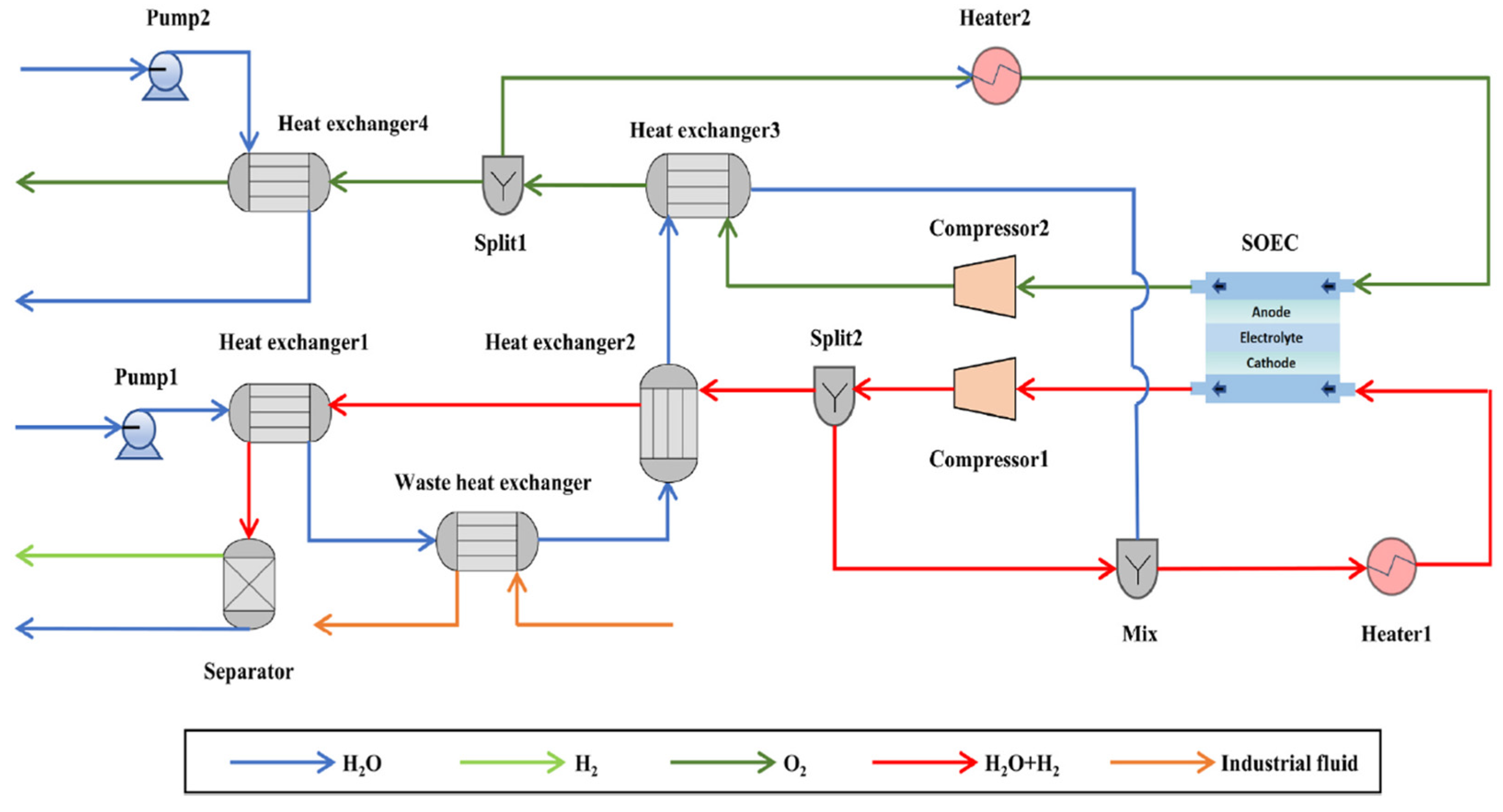
Figure 1 illustrates the proposed system by Zhao et al. [
10], in which the electrolyzer is integrated into a process that recovers waste heat via a heat exchanger. This exchanger is used to produce steam at 130 °C. However, the SOEC operating temperature (800 °C) is achieved through process integration and the use of electrical energy.
Moreover, apart from the thermal integration, partial hydrogen recirculation is necessary to obtain a reducing atmosphere on the cathode side, which is essential for the correct stack operation. In that case, the gas mixture entering the cathode consists of 90% steam and 10% hydrogen. On the anode side, air is used as a sweep gas to remove the produced oxygen.
Following a similar approach to Zhao et al. [
10], Wu et al. [
11] also include an integrated system that utilizes waste heat from an industrial process via a dedicated heat exchanger [
11]. The configuration closely resembles that described by Zhao et al. [
10] as can be observed in
Figure 2.
Furthermore, Cho et al. [
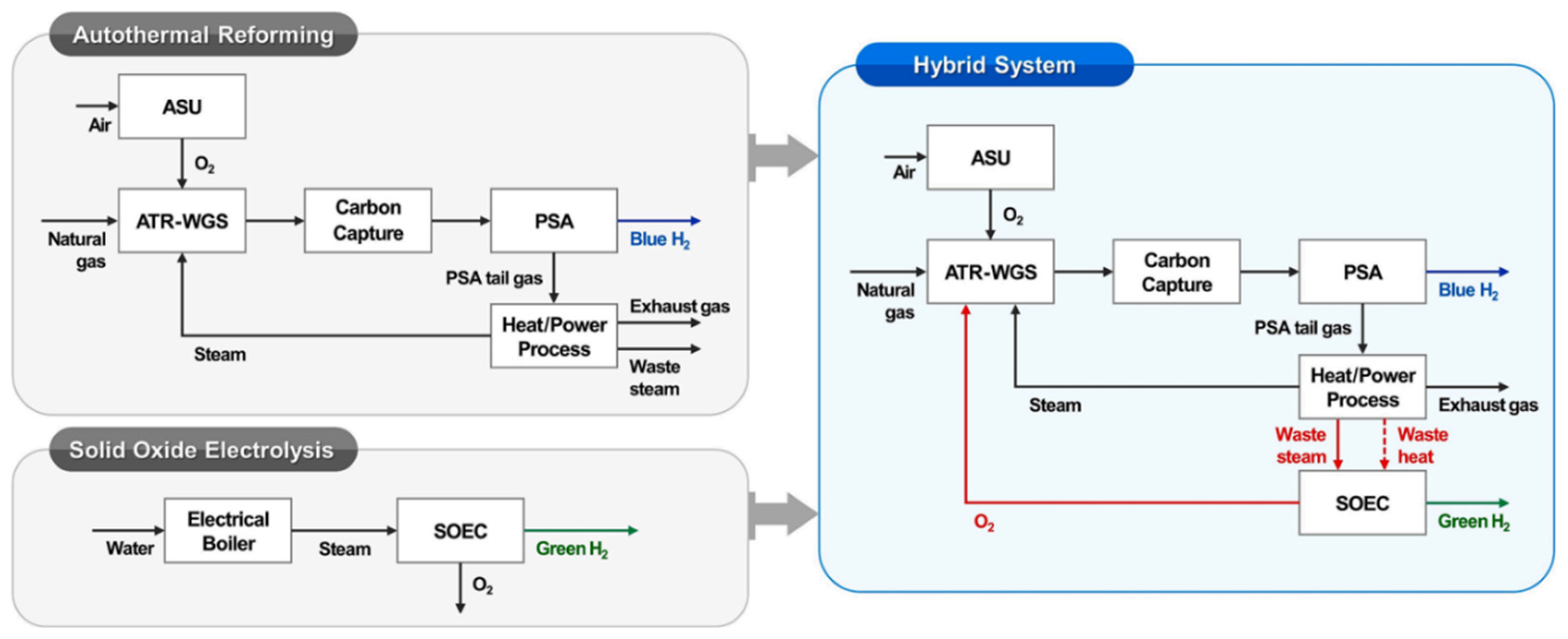
12] evaluate the possibility of SOEC integration in an autothermal reforming process. In their proposed configuration, both the residual heat and the steam generated during autothermal reforming are utilized, as can be seen in
Figure 3. Besides, the autothermal reforming process requires a supply of pure oxygen, which is provided by the electrolytic cell.
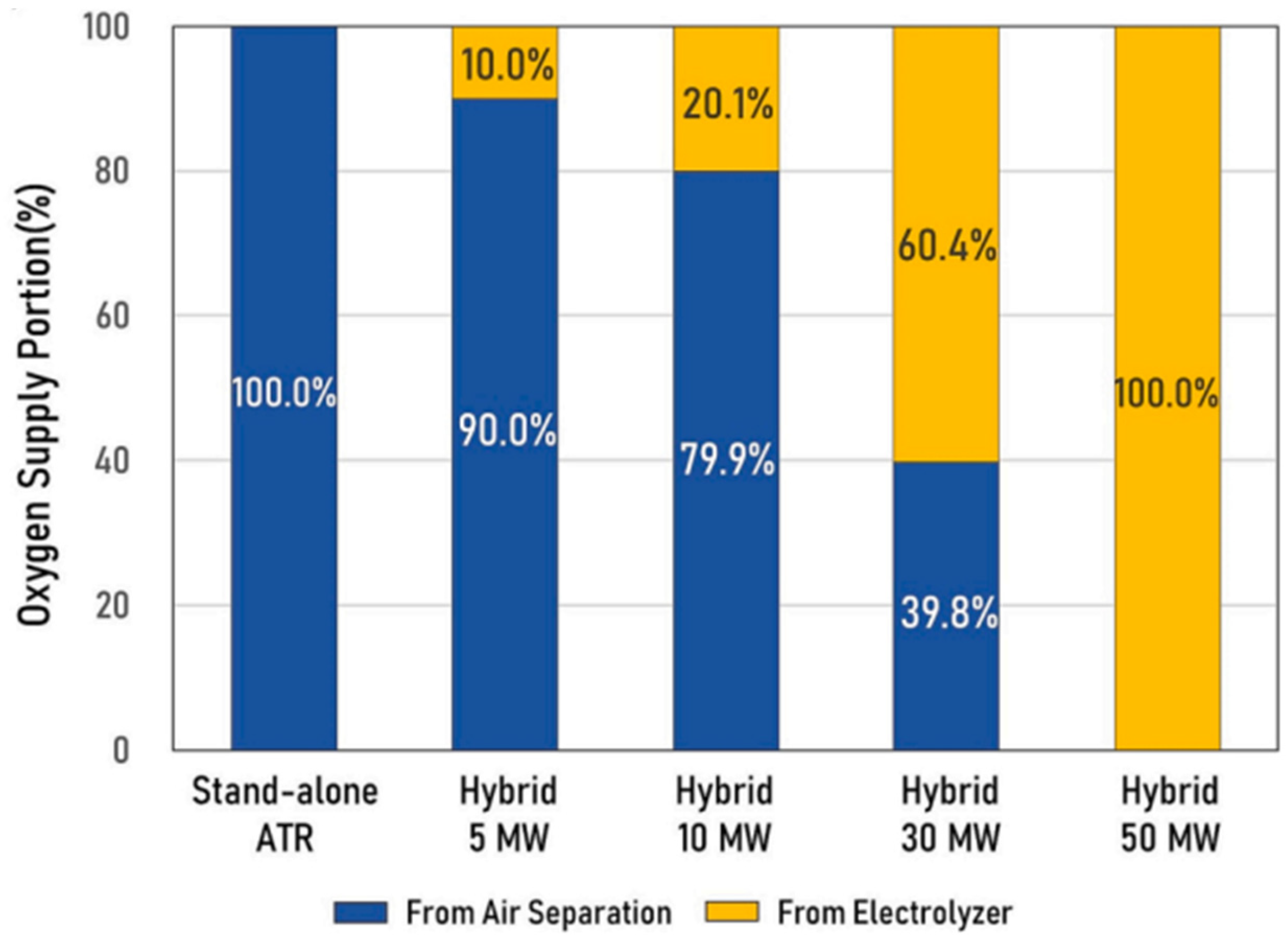
Electricity for the process is generated by using excess steam in cogeneration. Therefore, the amount of waste steam available decreases as the stack power increases. This relationship is illustrated in
Figure 4, where SOEC power is related to oxygen supplied from the Air Separation Unit (ASU).
Additionally, ref. [
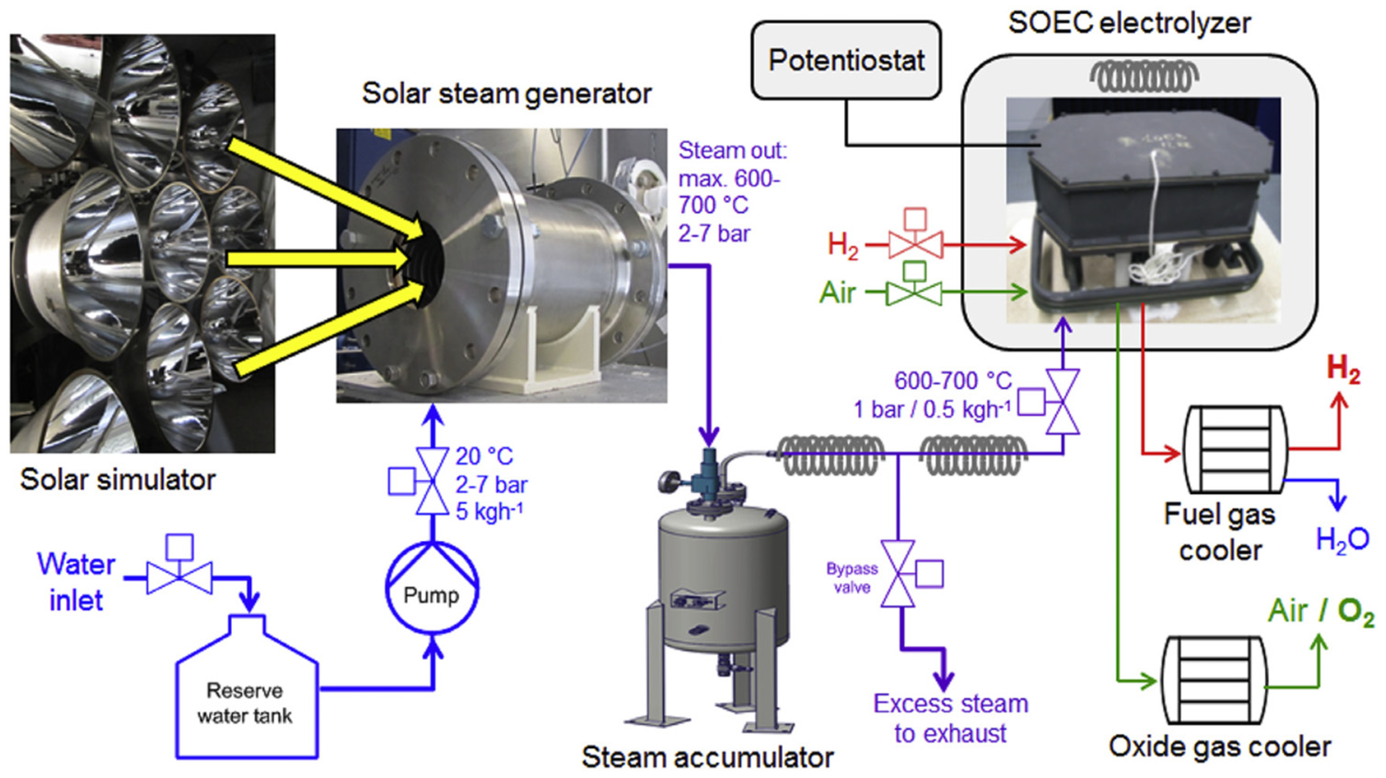
13] the integration of SOECs for hydrogen production using solar thermal energy as the heat source has been experimentally investigated. Schiller et al. [
13] presented an experimental setup, shown in
Figure 5, to evaluate this configuration.
In the mentioned system, the solar steam generator is responsible for concentrating the solar radiation to produce superheated steam, which is then stored in the steam accumulator. As for the SOEC stack, it consists of 12 units connected in series within a thermally insulated enclosure that maintains the required operating temperature. In this study, a steam conversion to hydrogen of 70% with a cell electric efficiency of 93% is achieved.
In a related work, Chen et al. [
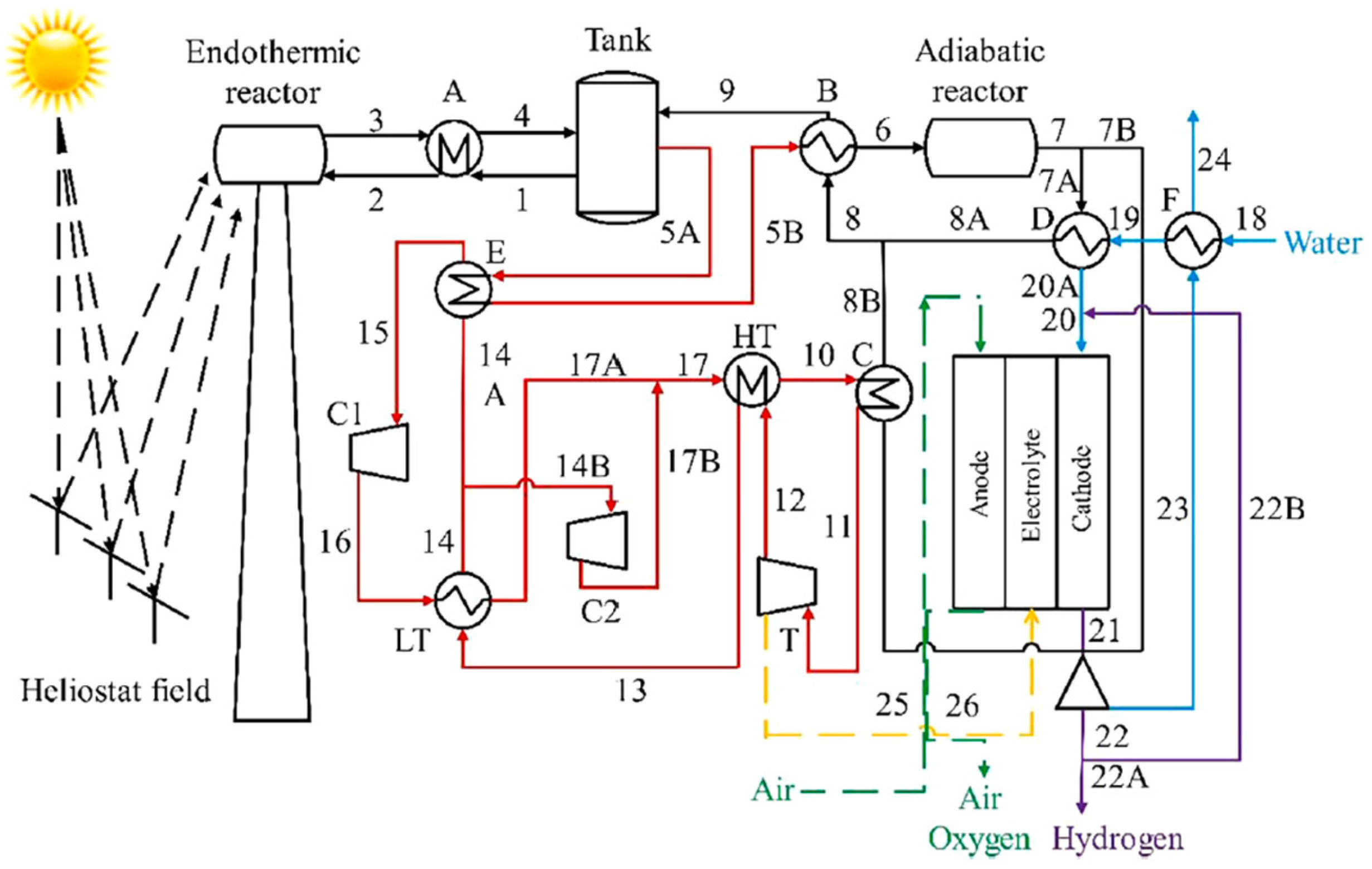
1] presented a solar hydrogen production system integrating SOEC with ammonia-based thermochemical energy storage. Within the proposed diagram (
Figure 6), three subsystems that comprise the process can be distinguished: thermochemical energy storage (TCES) (black streams), a supercritical CO
2 Brayton cycle (red streams), and the SOEC system.
For the TCES, two reactors are employed: one for ammonia decomposition (endothermic reactor) and another for ammonia synthesis (exothermic reactor), based on the following reversible reaction (1):
Water heating up to the SOEC cathode inlet is achieved by mixing the incoming water stream with the cathode outlet stream, and using the heat exchanger “D”, which recovers thermal energy from the outlet of the adiabatic reactor, as shown in
Figure 6.
Regarding the operating conditions of the electrolytic cell, the key parameters include a temperature of 973 °C and a pressure of 1 bar.
2.2. Methane Production
Methane is one of the most widely available energy sources, representing the primary component of natural gas. It is commonly used for electricity generation and as a transportation fuel, among other applications.
Additionally, it serves as a raw material in numerous industrial processes, such as hydrogen production and ammonia synthesis. Below, there is a classification of the different approaches to integrate SOEC into the methanation process.
2.2.1. Via Electrolysis
On one hand, methane can be produced by mixing a CO2 stream (captured from a process) with hydrogen generated via electrolysis at the reactor inlet.
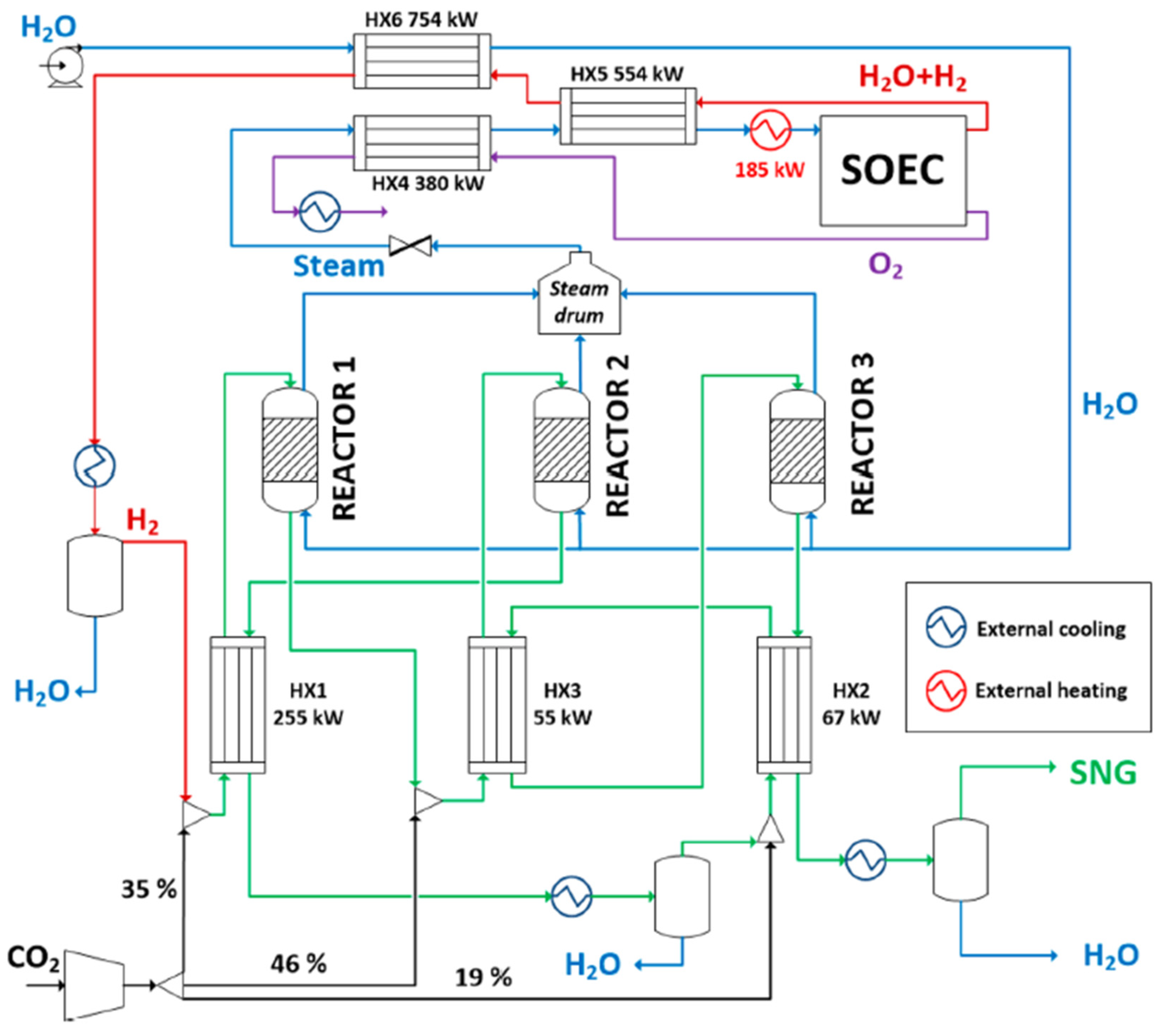
In this context, Giglio et al. [
14] proposed integrating an SOEC for hydrogen production within a methanation process. The integration strategy utilizes the reaction heat from methanation to generate steam before its entry into the cell. To achieve the steam target operating conditions before entering the SOEC (15 bar and 800 °C), additional electrical heating is applied, as shown in
Figure 7.
This approach results in energy savings, as evidenced by tracking the water flow from its entry into the process to its arrival at the SOEC. Along this path, water acts as a coolant in the methanation reactors and undergoes heat exchange with the outlet stream from the electrolytic cell.
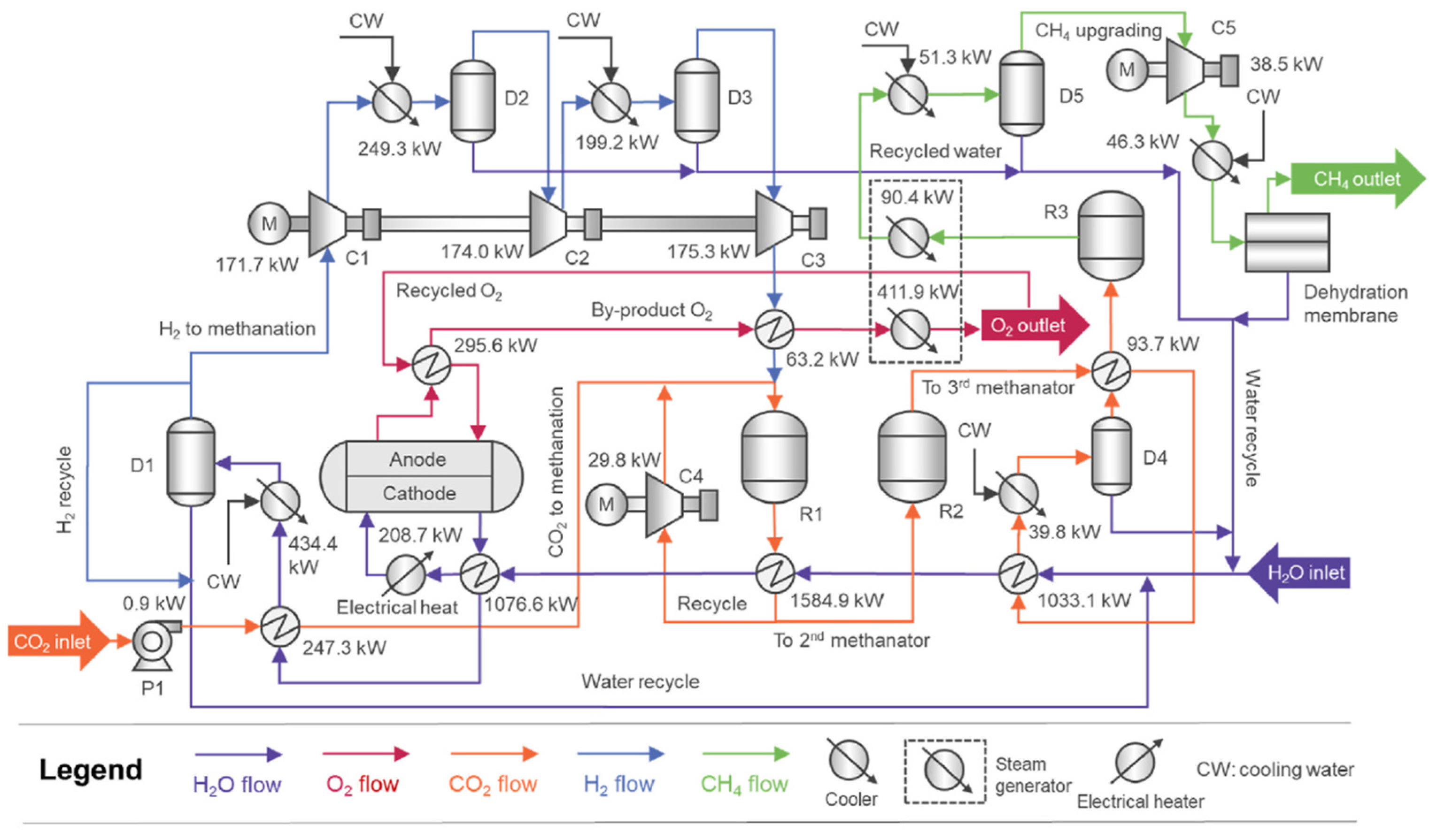
Qi et al. [
3] proposed a method to supply energy for the electrolysis through a system called LCES, which stands for “Liquid CO
2 Energy Storage”. This concept involves thermo-mechanical energy storage using compressors and turbines for electricity storage and generation within a thermodynamic cycle. Liquid CO
2 is used to obtain a continuous and flexible renewable-PtM process as a regulator to manage the intermittent nature of the power supply and fluctuations in gas demands as well as electricity prices.
In the process, shown in
Figure 8, the integration of the electrolytic cell can be observed through water’s trajectory across a series of heat exchangers. These exchangers utilize the outlet streams from the methanation reactors and the cathode outlet stream, while additional electrical heating is employed to reach the required temperature. The PtM process realizes heat self-sufficiency and achieves a lower heating value-based efficiency of 77.2%.
Through these process integrations, specific electricity consumption can be reduced to 35.9 kWh/kgH2. It is ensured that methane produced from renewables will be cost-competitive with conventional routes in a future scenario.
2.2.2. Via Co-Electrolysis
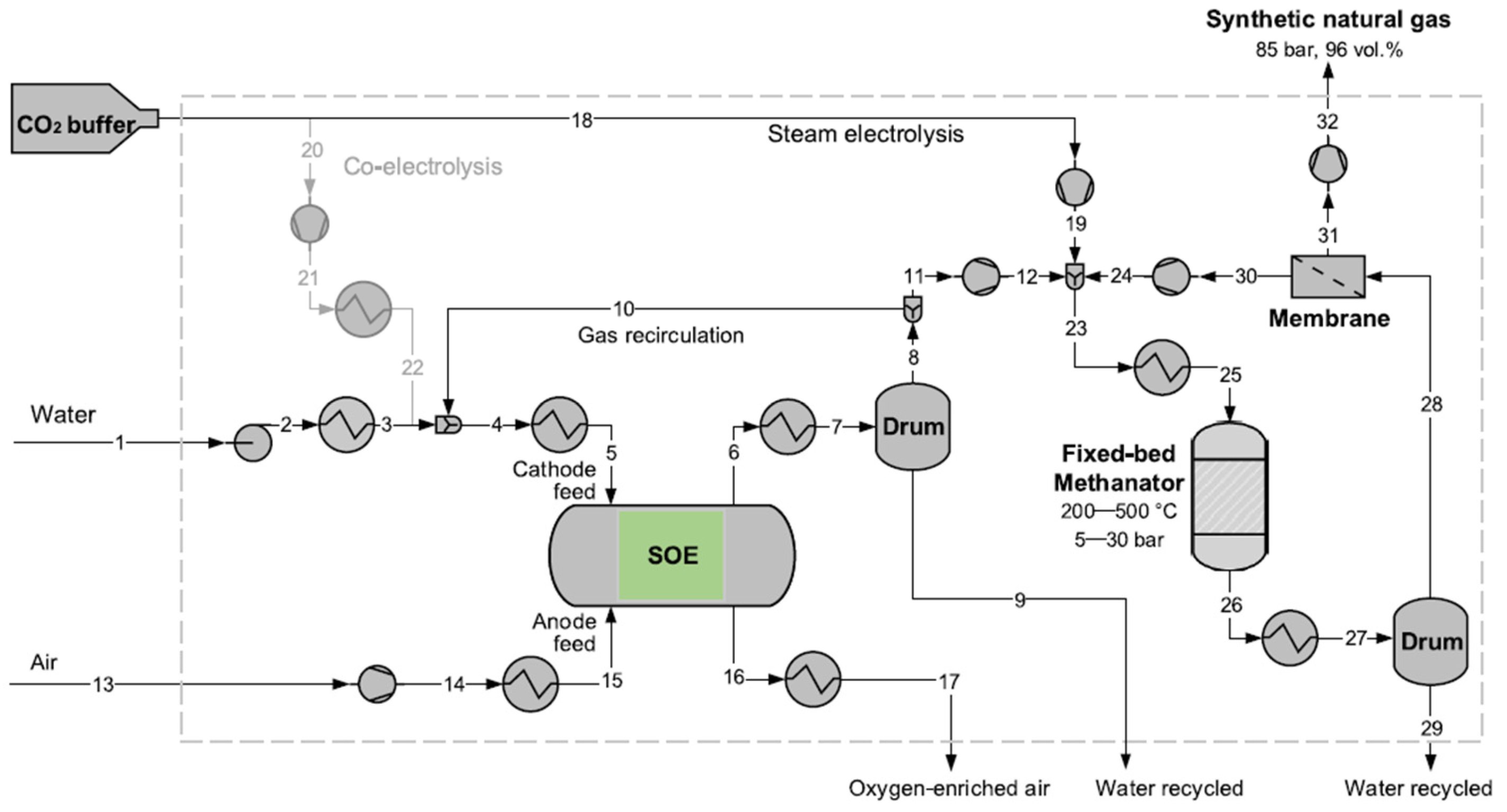
Methanation can also be achieved through co-electrolysis as demonstrated in the work of Wang et al. [
2], where SOEC is integrated into a Power-to-Methane system. In this process, presented in
Figure 9, maximum efficiency values of up to 85%, based on the high heating value (HHV), are reached for different operational cases with the following operational conditions: 700 °C and 26 bar.
Wang et al. contemplate that “Internal methanation can serve as an effective internal heat source to maintain stack temperature” [
2], which is an interesting way to keep the stack temperature high when the stack is operated at low current density. But it needs to be monitored closely due to the reaction being strongly exothermic.
However, there is a maximum methane fraction inside the stack, being 15 vol.% at 15 bar without dry gas, because a higher system efficiency is achieved.
In this process, there are two different options: CE (co-electrolysis) and SE (seam electrolysis). For the CE process, CO2 is fed directly to the SOE (solid oxide electrolyzer) with the water fed stream and the recirculated gas, while in the SE process, the CO2 is fed to the methane synthesis place where H2/CO2 = 4 (molar-based ratio).
For the desired purity of the methane, a membrane is used to reach 98 vol.% for transportation fuel and 96 vol.% for gas grid injection.
On the other hand, Ancona et al. [
15] addressed a SOEC thermal integration within a Power-to-Gas system. Although no specific thermal source is specified in the study, the heat exchangers are supplied with thermal energy, as can be seen in
Figure 10, represented by red arrows. In addition, the electricity required for the process is assumed to be supplied by renewable energy sources.
To describe the process, both streams (H2O and CO2) with external heaters are preheated up to the operating temperature. Additionally, sweep air is also preheated to feed it into the anode side, so air rich in oxygen is produced in the SOEC, while at the cathode outlet side, a stream with the co-electrolysis reaction products is produced.
Then the cathode side stream is fed to the HTM (high temperature methanation) reactor to produce a rough SNG to carry the rough SNG to the LTM (low temperature methanation) and improve the methane content in the conditioning line so a treated SNG is obtained for the NG network.
In this study, the SOEC operating temperature is 850 °C, with an inlet molar composition of 80% water and 20% CO2. The electrolytic cell has a power rating of 1 MW, achieving 80% conversion of both water and CO2. At the anode outlet, the stream composition is 50% oxygen.
Moreover, an integration of SOEC as a co-electrolyser was proposed by Sánchez-Luján et al. [
16] in a Power-to-Liquid process. The integration occurs between the SOEC and the syngas outlet of the catalytic partial oxidation reactor (CPOX reactor), which operates at 1000 °C.
The operating temperature of the SOEC is 800 °C, which is achieved through this thermal integration and by generating steam, recovering heat from the cathode outlet stream.
A key advantage of operating the CPOX reactor in parallel with the SOEC is that if the electrolytic cell does not have sufficient capacity due to the intermittency of renewable energy sources, the reactor can compensate for the syngas demand.
At the system level, with the integration of the co-electrolyser, an electrical efficiency of 84% is achieved. In this paper, the impacts of current density and operating temperature on the system are addressed.
2.3. Methanol Production
Methanol is a widely used compound in the chemical industry and is typically produced from syngas. Therein lies the possibility of SOEC integration into this process, particularly through the co-electrolysis mode, which enables direct syngas production.
An et al. [
17] proposed the integration of an SOEC stack in the coal-to-methanol process to replace, partially or totally, the water–gas shift (WGS) reactor. This integration is illustrated in
Figure 11.
As illustrated in the scheme, the process begins with coal gasification to produce raw syngas. To obtain an appropriate CO/H
2 ratio for the methanol synthesis reactor, it is common to apply the WGS reaction:
However, in this integration, the WGS reactor is replaced by an SOEC. The main advantage of this substitution is the improvement in coal utilization efficiency. In the WGS reaction, hydrogen is produced at the expense of CO and with the simultaneous formation of additional CO
2 (undesirable). In consequence, the CO/CO
2 ratio deteriorates, which negatively affects the methanol synthesis stage, where the main reaction is:
An et al. [
17] concluded that the integration of SOEC results in a 2.2-fold increase in methanol production, the CO
2 emissions are reduced in 0.16 t CO
2 per 1 MW of coal energy input since it is not produced in the WGS reaction, and achieves an improved thermal energy conversion efficiency.
This alternative becomes economically viable only under conditions of high carbon taxes and greenhouse gas (GHG) emissions taxes. Under such circumstances, its economic performance is 2.1 times better than the base case.
Profitability can be further improved by replacing coal with biomass gasification, as proposed by Ali et al. [
18]. The combination of both technologies increases the methanol conversion efficiency from 50% (using only gasification) to 72.08% (using gasification with SOEC). Moreover, the oxygen produced in the SOEC can be introduced to the gasification process as a gasifying agent, and the energy required to vaporize the water for the SOEC can be supplied by the heat content of the output products.
An et al. [
17] also concluded that this integration reduces GHG emissions by 94% in relation to the conventional coal-to-methanol process, thereby making the system more competitive even though the SOEC electric consumption is much higher than the WGS reactor.
From a different perspective, Khan et al. [
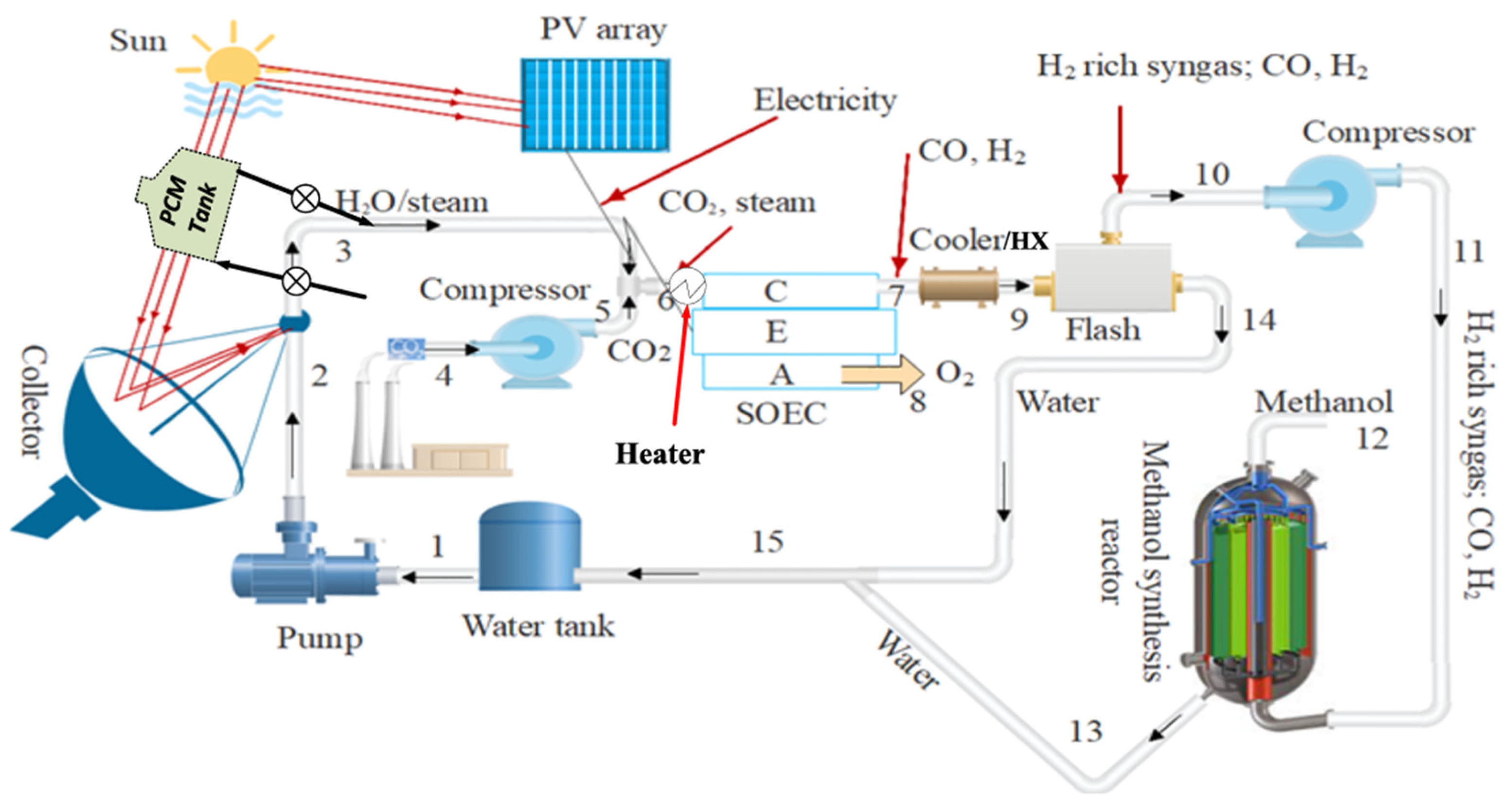
19] proposed a methanol production system that combines solar energy and thermal energy storage using molten salts (as a phase change material, PCM) with syngas production in a SOEC co-electrolysis stack that feeds the methanol synthesis reactor. In
Figure 12, a general process scheme with the most important units is shown.
To harness solar energy, the system includes a photovoltaic station with sufficient capacity to power all the stacks. In addition, to collect the thermal energy, a parabolic disk is employed to concentrate the solar radiation and transfer the thermal energy to the molten salts circuit for storage.
Solar radiation is focused onto the parabolic disc, which has a surface area of 285 m2. The concentrated energy is then transferred to the PCM, providing a total thermal capacity of 200 MW. On the other hand, the photovoltaic system generates 500 MW of electricity for the SOEC operation.
The CO2 used in the process is captured from other industrial sources. It is preheated, compressed, and mixed with steam to reach a temperature of 800 °C before entering the cathode of the electrolytic cell.
Khan et al. [
19] studied parameters of interest for the system’s application, including the influence of Direct Normal Irradiance (DNI) on overall performance. They conclude that a high DNI enhances both the energy and exergy efficiency of the parabolic dish system. In contrast, as illustrated in
Figure 13, the effect of DNI on the photovoltaic subsystem exhibits a slightly different behavior.
In this case, at high irradiance levels, the electrical performance of the photovoltaic system decreases compared to lower irradiance conditions. This decline is attributed to the fact that the equipment reaches high temperatures, which negatively affects its efficiency. Nevertheless, overall methanol production increases with higher DNI, despite this effect, and consequently leads to a reduction in methanol production cost.
The authors also examine key cell operation parameters such as internal gas density and operating temperature. Their findings indicate that higher gas densities and operating temperatures result in increased hydrogen and syngas production rates within the SOEC.
2.4. Liquid Fuels Production
A particularly promising integration option within the ongoing energy transition, driven by the increasing adoption of biofuels, is the introduction of SOEC technology into the biomass-to-liquid process, as proposed by Steinrücken et al. [
4].
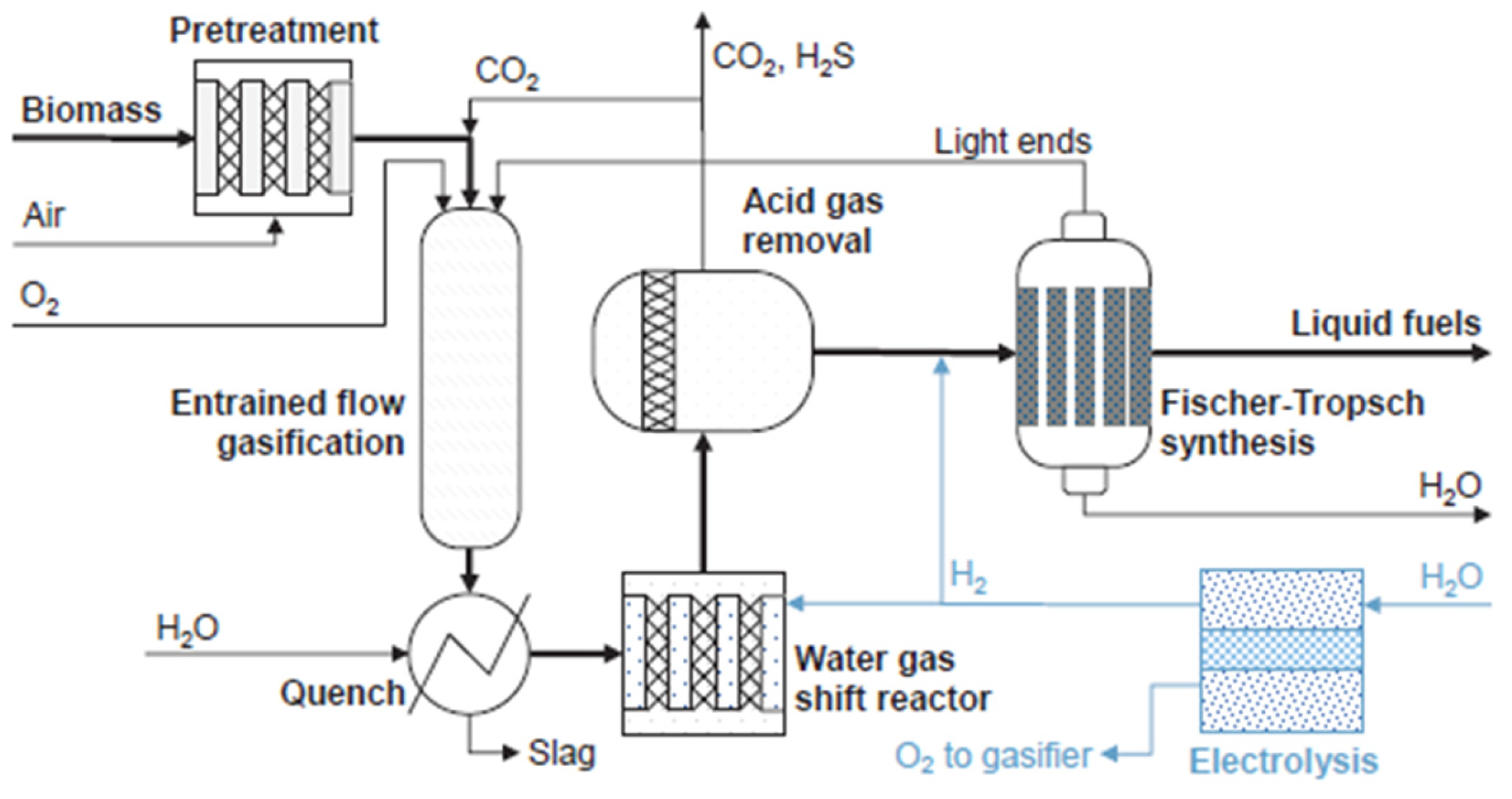
They present a conceptual framework for sustainable aviation fuel (SAF) production from biomass, incorporating SOECs through three possible integration pathways, as illustrated in the simplified scheme shown in
Figure 14.
To this end, the integration of SOEC technology is proposed in three alternative configurations, each aimed at increasing the hydrogen content of the syngas. These integration pathways are schematically represented and explained in
Table 1.
In the first case, the electrolysis cell operates in combination with the WGS, providing the gasifier with oxygen, partially or fully replacing the air separation unit (ASU). In the second case, the WGS reactor is omitted, and all the hydrogen required to adjust the H2/CO ratio of the syngas is supplied by the SOEC. The third alternative involves operating the WGS reactor in reverse mode, utilizing the excess CO2 as a reactant.
In all cases, it is necessary to remove the CO2 from the gas stream before being introduced into the FTS reactor. Part of this CO2 is processed by the PSA, and the remainder is recirculated to the EFG and used as a gasifying agent.
Once the syngas stream has been treated, it is fed into the FTS reactor at 230 °C and 20 bar. At the FTS outlet, two streams are produced: liquid fuel and gas. The gaseous stream contains non-converted compounds, and can be recirculated to the FTS inlet or the EFG entry, increasing the process efficiency. The liquid stream corresponds to a hydrocarbon product that, after undergoing refining steps, can be upgraded to Sustainable Aviation Fuel (SAF).
The SOEC stack operating temperature is 800 °C and is thermally integrated with the outlet stream of the EFG at 1200 °C.
In configurations that do not include the WGS reactor, two integration strategies for the SOEC are proposed, as shown in
Figure 15a,b. The first option involves using the stack to reform the outlet FTS gas stream. The second option places the SOEC upstream to reform the gas exiting the EFG.
The first configuration presents the advantage of not introducing light hydrocarbons in the cell, which could produce carbon accumulations. In addition, the obtained H2/CO ratio is constant and equal to 2.1, in contrast to case II.
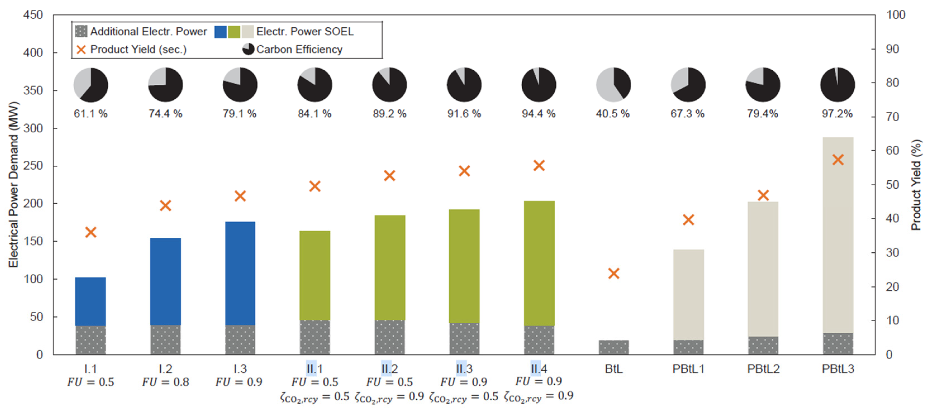
Figure 16 compares performance variables for the different integration configurations described above. The figure illustrates the required electric power for SOEC operation, product yield, carbon efficiency, additional electric energy input, and Fuel Utilization (FU).
The product yield refers to the efficiency of conversion to liquid fuels (i.e., synthetic crude), while FU quantifies the efficiency between the stack inlet and outlet when the SOEC is used for reforming, either the FTS outlet gas stream or tars from the EFG.
The additional electric energy corresponds to the inlet heating required for co-electrolysis. According to pinch analysis, this heat demand cannot be fully covered by process steam and therefore varies depending on the integration case.
It can be observed that Case I presents a lower electric power demand but achieves lower conversion rates than Case II. Among the original integration options, Case 3 has the highest energy demand, while the base case results in the lowest product conversion.
The choice between configurations ultimately depends on an economic assessment, which is beyond the scope of this work. Given the available data, it is not possible to draw definitive conclusions.
Sánchez-Luján et al. [
16] suggested the integration of a 100 MW SOEC in a power-to-liquid plant that produces syngas by flue gas from other industrial processes in a CPOX reactor and via solar-powered co-electrolysis in the SOEC. A general overview of the process is shown in
Figure 17.
The process includes a CPOX reactor that partially oxidizes off gases, tail gases, or even biogas with high content in methane and other light hydrocarbons such as propane and butane, to produce syngas. This reactor operates in parallel with the SOEC, producing green syngas. The used CO2 derives from carbon capture from other industrial processes.
The syngas produced in the CPOX reactor, at 1000 °C, is thermally integrated with the SOEC stack. The study includes a pinch analysis that proves the viability of integration, enabling the stack to reach its operating temperature of 800 °C.
The syngas generated by both pathways (co-electrolysis and CPOX) is fed to a Fischer-Tropsch reactor to produce liquid fuels. Following synthesis, a separation system is employed to isolate the liquid products from the unreacted syngas, which is then recirculated back into the reactor.
Focusing on the operation of the electrochemical cell, co-electrolysis requires more energy than conventional electrolysis due to the higher enthalpy of the implicated substances. Consequently, maximizing energy integration is essential. The stack inlet is therefore integrated not only with the CPOX product stream but also with the SOEC outlet gases to recover heat.
To achieve a syngas composition with an H2/CO ratio of 2.1, water and steam are mixed and preheated to 550 °C using the SOEC outlet gases. CO2 is separately preheated to 375 °C, and then both are combined and further heated to 800 °C using the energy from the CPOX syngas stream. The resulting syngas is collected at the SOEC cathode, while the anode produces oxygen-enriched air (approximately 50% O2), which can be valorized in other industrial processes.
Sánchez-Luján et al. [
16] simulated the described system using ASPEN Plus, obtaining a SOEC energy cell efficiency of 84%, a power to syngas efficiency of 78% and a power to liquid efficiency of 49%. In addition, the synthesis reactor produces 30 MW of MP steam that is not necessary for the process thanks to full thermal integration across all streams.
While the pinch analysis supports the thermodynamic feasibility of the integration, an assessment of techno-economic viability is necessary for a comprehensive evaluation.
2.5. Electricity Generation
SOECs can be integrated into electricity generation systems, using the hydrogen produced as both an energy vector and a form of energy storage. This hydrogen can subsequently be employed as fuel in an SOFC.
Liang et al. [
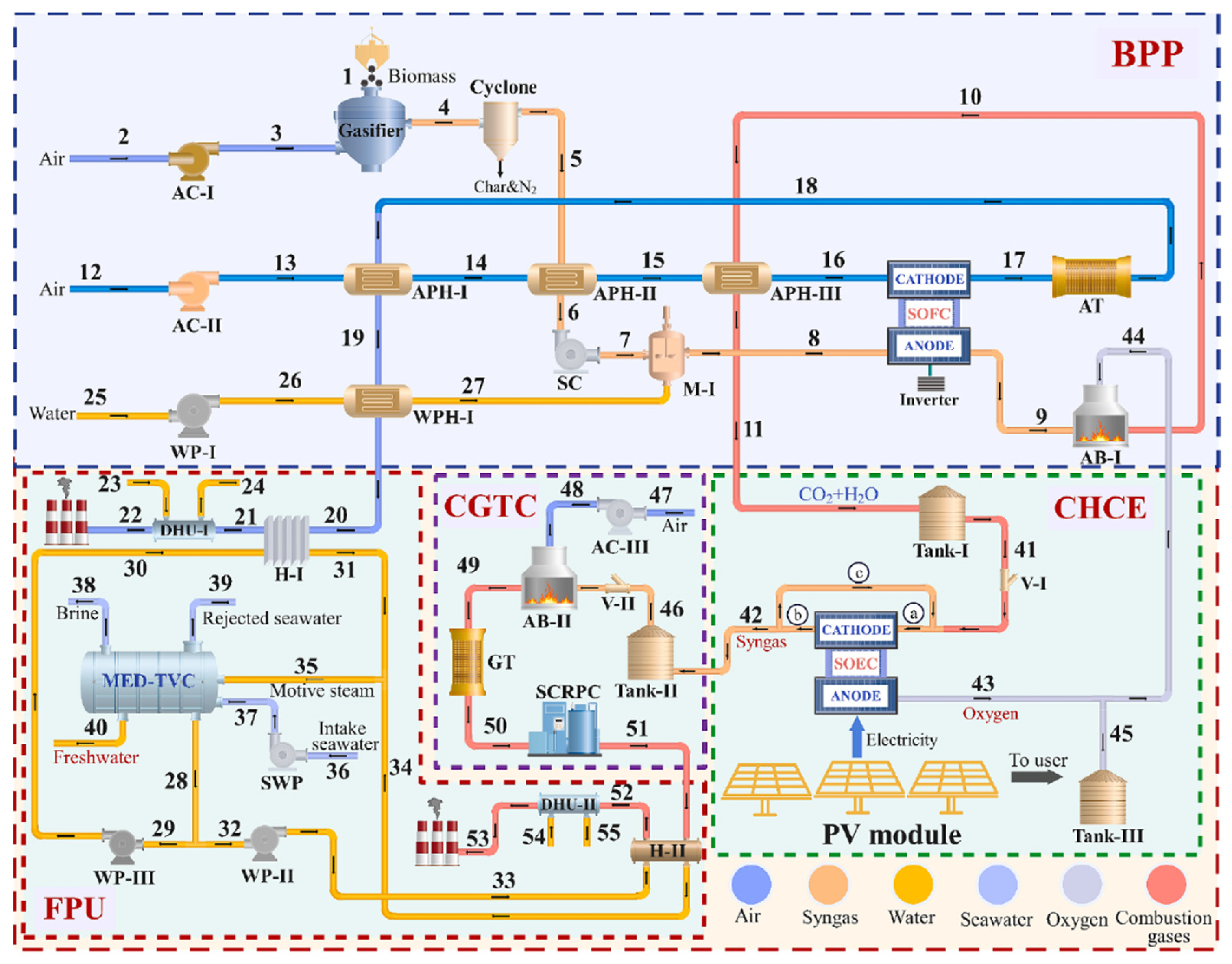
20] presented a novel system to produce electricity that combines a SOEC stack and a SOFC stack with the aim of maintaining continuous power generation based on solar energy, including during nighttime hours.
Figure 18 presents a simplified scheme where the principal units of the system are represented.
At night, a gasificator is utilised to produce syngas, which, together with the stored syngas from daytime operation, is fed to the SOFC to generate electricity for both consumers and the auxiliary systems. Those subsystems are designed to utilize the residual energy still present in the outer system flows, either to produce additional electricity or to generate other useful products.
Figure 19 shows a detailed scheme of the complete system, excluding the photovoltaic plant.
The nocturnal operation of the system is initiated through the activation of the gasifier, which supplies fuel to the SOFC. During this phase, carbon dioxide is accumulated in Tank 1 for use in the daytime mode, while valve V1 remains closed.
In contrast, during the daytime operation, syngas is produced by the surplus electricity generated by the PV cells and the accumulated CO2 produced by the SOFC. This syngas is then used to supply the cogeneration plant and the freshwater production unit. For the simulation, a temperature of 800 °C and an electric efficiency of 92.02% are assumed for the stack. The results yield an exergetic efficiency of 50.67% and an energetic efficiency of 43.68%. Although the energy efficiency is relatively low, the exergy performance is notably high.
From an economic perspective, the simulation reports a total product cost of 45.44 $/h and a levelized cost of 14.61 $/GJ. The projected annual production includes 17,485 tons of freshwater and 1432 tons of oxygen available for sale. However, no reference to the annual financial profit of the plant is provided, making the economic viability assessment incomplete.
The proposed system presents a promising concept, but still requires further research and more detailed economic analysis to assess its feasibility. This challenge is compounded by the fact that several of the technologies involved, such as gasification and reversible SOEC/SOFC systems, have not yet reached industrial-scale implementation.
Furthermore, Königshofer et al. [
21] conducted an experimental study on the performance of an rSOC stack. The system delivers a power output of 20 kW when operating in fuel cell (FC) mode. Its primary function is to produce green hydrogen with the excess energy and to serve as a backup power generator.
This study can be categorized into three operational modes: EC mode, FC mode, and alternating mode. In EC mode, the stack operates at 830 °C and its voltage and temperature were measured at different H2O/H2 ratios as a function of current density, using ramping rates.
An increase in the stack core temperature was observed at higher current densities. At lower current densities, thermodynamic effects in the stack performance gained importance. Moreover, the influence of elevated temperatures was found to be more dominant than that of increased steam concentration.
In FC mode, the temperature operation was around 800 °C at higher power outputs and fuel utilization within operational limits. Voltage and temperature measurements were conducted as functions of current density, using various inlet flow rates. The results indicated that higher power outputs were obtained when higher fuel flow rates were combined with slower ramping rates.
During alternating operation mode, comprising five cycles over a total of 120 h, with transitions between electrolysis (EC) and fuel cell (FC) modes every 12 h, the maximum temperature remained below 860 °C. These operating temperatures were consistent with those employed during the system’s stability tests.
2.6. Nuclear Energy Integration
Nuclear energy currently remains highly controversial due to the significant risks associated with its use and the generation of radioactive waste. However, it is capable of generating energy from a small amount of raw material. Nowadays, there are numerous nuclear power plants in operation worldwide, and nuclear reactors represent a promising option to integrate an SOEC cell, given the continuous highly exothermic reactions that occur within them.
Kim et al. [
22] proposed the integration of a Very High-Temperature Gas-Cooled Reactor (VHTR), which operates at temperatures exceeding 950 °C, thus satisfying the thermal requirements of an SOEC. Their work involves the operation of a laboratory-scale model replicating the configuration of a nuclear plant with an integrated SOEC system.
Figure 20 presents a simplified representation of the system configuration and its principal components, excluding the reactor itself, but showing the helium circuit that supplies the nuclear reaction’s energy.
The system operates by transferring heat from the VHTR reactor to helium via a Printed Circuit Heat Exchanger (PCHE). The heated helium then flows to a multi-stream heat exchanger, where it is used to raise the temperature of both the steam for the SOEC and the air for the VHTR to their respective operating conditions.
The helium exiting the multi-stream exchanger still retains significant thermal energy, which is utilized in a steam generator to produce the steam subsequently introduced into the heat exchanger. The resulting preheated steam is then supplied to the SOEC, where hydrogen and oxygen-enriched air are produced. The latter can be sold as a byproduct.
The SOEC stack operates at atmospheric pressure and 820 °C, corresponding to the preheated steam temperature, and has a nominal electric power output of 30 kW.
The experimental tests demonstrated that approximately 9 h of operation are required to reach stable operating conditions. Although this duration would likely increase at an industrial scale, it does not represent a critical issue, given that industrial plants typically operate continuously for most of the year.
The experiments ultimately confirm that the nuclear reactor, in combination with a helium-based cooling system, can reliably support steam temperatures above 800 °C and air temperatures around 750 °C. However, an increase in pressure drop was observed at the outlet of both the steam and air pipelines in the multi-stream heat exchanger. This effect was attributed to oxide deposits forming within the pipes, resulting in a 50.6% reduction in heat transfer compared to the theoretical model. Nevertheless, the system was still able to achieve the required operating temperatures.
3. Critical Analysis
To provide a detailed comparative analysis of the different SOEC integration processes, a set of comparative tables is presented, featuring key technical information and data. One table is included for each of the main processes analyzed in
Section 2 (methane, methanol, hydrogen, and other products).
Table 2, corresponding to the methane production process, is presented below.
It can be observed that, across all articles, the reported thermal efficiency lies between 77–85%, values that exceed typical expectations. However, no clear trend can be established in relation to stack temperature or operating pressure.
Moreover, every study presents its results in terms of methane production, instead of being presented in terms of energy or hydrogen produced, suggesting that further development is needed to align the research more closely with industrial objectives, which prioritize final energy products.
Furthermore, all reviewed works remain at the experimental stage, not even reaching laboratory-scale implementations, but rather relying on process simulations carried out using tools such as ASPEN or MATLAB.
Table 3 collects the key data extracted from studies focused on methanol synthesis.
It can be observed that the articles are more focused on the final product, presenting more detailed parameters related to methanol, such as conversion to methanol and production enhancement data. Notably, the study by Khan et al. [
19] is primarily centered on the use of a molten salts circuit and does not report any data related to the final product; however, it provides valuable insights discussed in
Section 3.2.
Compared to the methane-focused studies, there is significantly less variability in terms of operating temperature and pressure. All studies are based on process simulations, and once again, none of them reach the experimental or laboratory scale.
Table 4 compiles the articles focused exclusively on hydrogen production.
In the case of hydrogen, there is a significantly higher number of studies focused on its production compared to other final products. In all reviewed works, the reported electrical efficiency exceeds 50%, with an average close to 80%, which represents a highly promising outcome in terms of energy conversion.
Regarding thermal efficiency, Chen et al. [
1] report a value of 70%. Although this figure may not appear exceptionally high, it is important to note that this study is the only one based on experimental data, and therefore reflects the technical and economic limitations inherent to laboratory scale. The same work also presents a solar-to-hydrogen efficiency of 23%. While this value may seem low at first glance, it aligns with the current state of the art when thermal energy storage is integrated, as indicated by the authors [
1].
In the case of Wu et al. [
11], the three reported electrical efficiency values correspond respectively to the overall system efficiency, the hydrogen production efficiency, and the hydrogen-to-electricity conversion efficiency. This distinction is essential to avoid misinterpretation of the results.
Cho et al. [
12] analyzed four different stack power configurations, each corresponding to a different case study. Among these, the 50 MW electrolyzer scenario yields the best performance, which is why it has been selected for inclusion in
Table 4.
Among all the reviewed works, the study by Schiller et al. [
13] stands out as the only experimental work. Despite being conducted at laboratory scale, it reports a steam conversion rate of 70% and a stack electrical efficiency of 93%, both of which are noteworthy results that support the viability of experimental implementation.
Table 5 includes articles focused on power-to-liquid applications, electrical energy production, and other configurations aimed at evaluating stack performance or process integration, although in many cases without assigning a specific purpose to the electrolysis products or even quantifying their production, as seen in the study by Kim et al. [
22].
In the power to liquid category, Steinrücken et al. [
4] presented a very high energy utilization efficiency. However, the study does not include data on power-to-liquid or power-to-syngas efficiency. Two of the studies in this category are experimental, both conducted at laboratory scale. The article by Kim et al. focuses on process integration and exclusively reports energy transfer parameters.
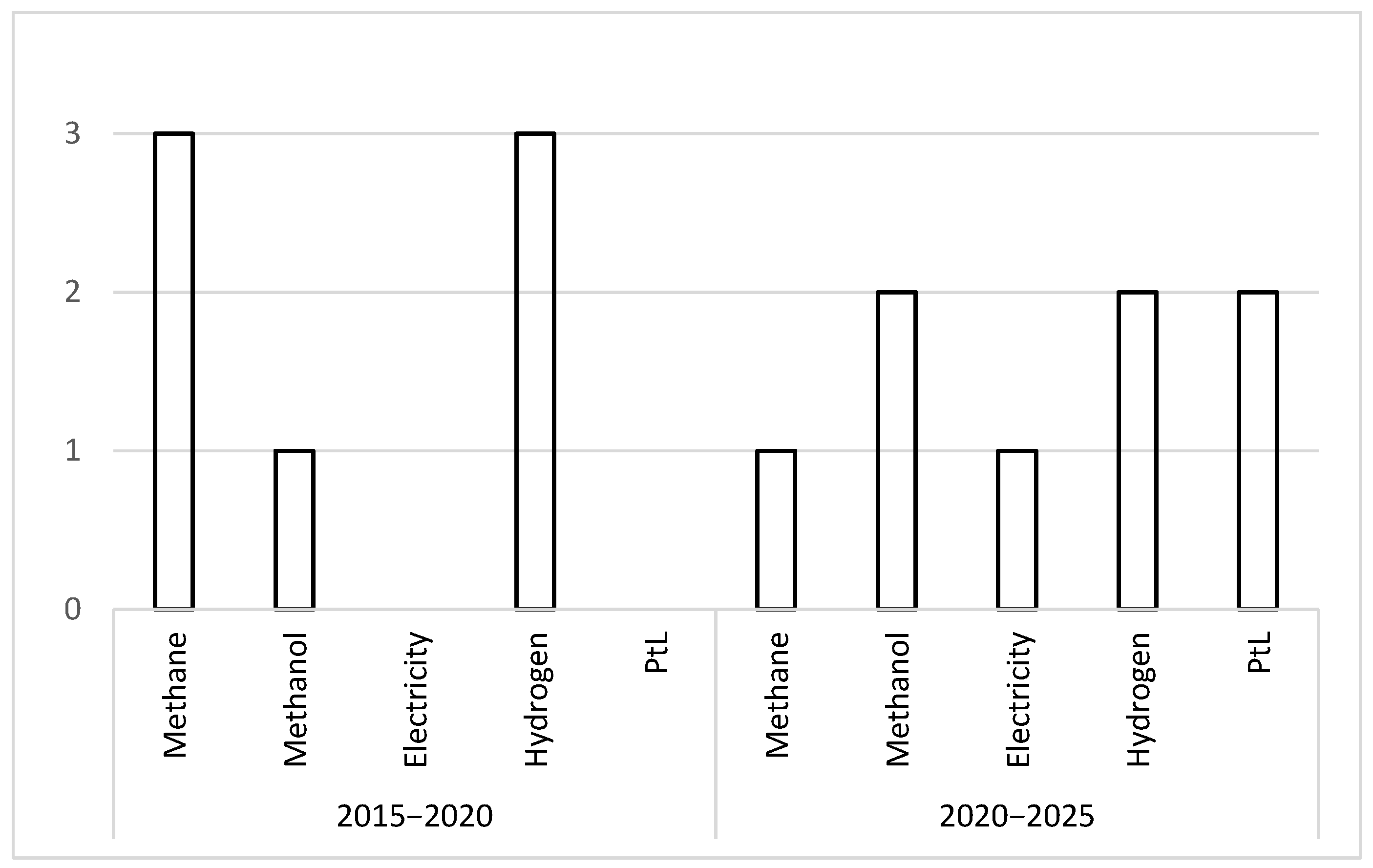
All the studies reviewed were published between 2019 and 2024. It is of particular interest to assess whether certain technologies or applications have gained momentum during this period. To explore this, the articles have been grouped by five-year periods and categorized according to their final product or intended application, as shown in
Figure 21.
During the first period, the focus was primarily on methane and hydrogen production, while in the second period, the use of SOEC technology became more diversified. The prominence of methane production declines significantly, even becoming secondary, while new applications such as power-to-liquid processes and electricity generation emerge.
This trend can be attributed to the increasing interest in SOEC systems and their versatility, particularly due to the possibility of producing syngas in co-electrolysis mode. Moreover, the broader energy context is increasingly oriented towards renewable fuels, as seen in power-to-liquid pathways where SOEC systems can be integrated. Renewable electricity generation, together with emerging technologies such as gasification, offers additional opportunities for synergy with SOEC.
Hydrogen production continues to be a dominant trend, reflecting the fundamental purpose of electrolyzers. Moreover, various industrial sectors currently rely on large-scale hydrogen consumption and are seeking to transition towards processes with lower greenhouse gas emissions.
To assess the progress that SOEC technology has made towards 2024 and 2030 targets, the key performance indicators (KPIs) presented in the report by Clean Hydrogen Joint Undertaking [
24] can be consulted. This progress is observed by comparing those KPIs, specifically those in
Table 6, with the results reported in the reviewed literature and presented in the comparative tables.
To begin with, KPI-1 refers to the electricity consumption and heat demand under normal operating conditions. In this regard, Zhao et al. [
10] reported a system heat demand of 0.61 kWh/kg H
2 (below the 2030 target of 8 kWh/kg H
2) and an electricity consumption of 3.16 kWh/kg H
2 (being the 2030 target of 37 kWh/kg H
2). These values indicate excellent performance relative to future benchmarks.
On the other hand, looking at KPI-7, which refers to the cell’s average current density, Wang et al. [
2] achieved 0.3 A/cm
2 by an Aspen simulation, Liang et al. [
20] set the current density at 3000 A/m
2 in a MATLAB simulation, which corresponds to 0.3 A/cm
2. Wang et al. [
2] also report a value of 10,000 a/m
2, which corresponds to 1 A/cm
2. Compared with the report’s targets (1.5 A/cm
2 in 2030), the paper reporting 1 A/cm
2 is closer to the 2030 target.
Finally, KPI-9 addresses the reversible capacity of the SOEC system, defined as the ratio of the nominal rated power in fuel cell mode to the electrical power at nominal capacity in electrolyzer mode [
24]. Ficili et al. [
24] proposed a reversible cell with a reversible capacity of 33.33%. This value indicates that the technology is progressing toward the 2030 target and highlights the growing potential of reversible SOEC systems.
3.1. Techno-Economic Challenges
To begin addressing the techno-economic considerations, a comparison between SOEC and other technologies is required. For this purpose, Ancona et al. [
15] classified electrolytic cells based on their working temperature: low and high-temperature cells.
Low-temperature cells (operating below 100 °C) include Proton Exchange Membrane (PEM) and Potassium Hydroxide (KOH) technologies, both of which are currently available on the market. In contrast, high-temperature cells (operating between 600–1000 °C) are based on Solid Oxide Electrolysis Cell (SOEC) technology.
A key difference lies in their efficiency. High-temperature cells can reach efficiency values approaching 100%, whereas low-temperature cells typically operate at efficiencies between 50% and 70% [
15].
Additionally, Ali et al. [
18] stated that there is a perfect match between high-temperature electrolysis and high-temperature processes such as gasification and fuel synthesis. They further point out that “the generated heat can be used to decrease the electric energy demand of the SOEC.” This underscores one of the main advantages of SOEC: its capacity to utilize thermal energy to reduce electrical consumption.
Ali et al. [
18] also concluded that the theoretical electricity demand for high-temperature SOEC systems is lower than that of low-temperature electrolysis technologies, due to the thermal contribution at elevated operating temperatures.
After comparing different electrolytic cells, the focus shifts to variables that can either harm or enhance the efficiency of the cell. One critical factor is the continuity of energy supply, as explained in
Section 3.2.
Another important variable is the residual heat available in the process into which the SOEC is integrated. The greater the amount of residual heat that can be utilized by the SOEC system, the lower the operating costs, mainly due to reduced demand for external steam production and heating.
Additionally, the hydrogen concentration in the feed stream to the electrolyzer must be considered. A certain hydrogen content is necessary to maintain a reducing atmosphere, preventing electrode reoxidation, as noted by Ancona et al. [
15].
Finally, from an economic perspective, it is important to consider that most of the current projects are at the laboratory or pilot plant scale. As a result, scaling-up costs represent a critical challenge and a focal point for future development.
Noordende et al. [
25] highlighted that “the overall system design needs to balance each of the aspects of the system and indicate the optimal module size based on a compromise between decreasing specific CAPEX and increasing OPEX”. In other words, while increasing system size leads to a reduction in the specific capital expenditure (CAPEX) per module, it also results in higher operational expenditure (OPEX). Therefore, achieving an optimal system design requires finding the right balance between CAPEX and OPEX.
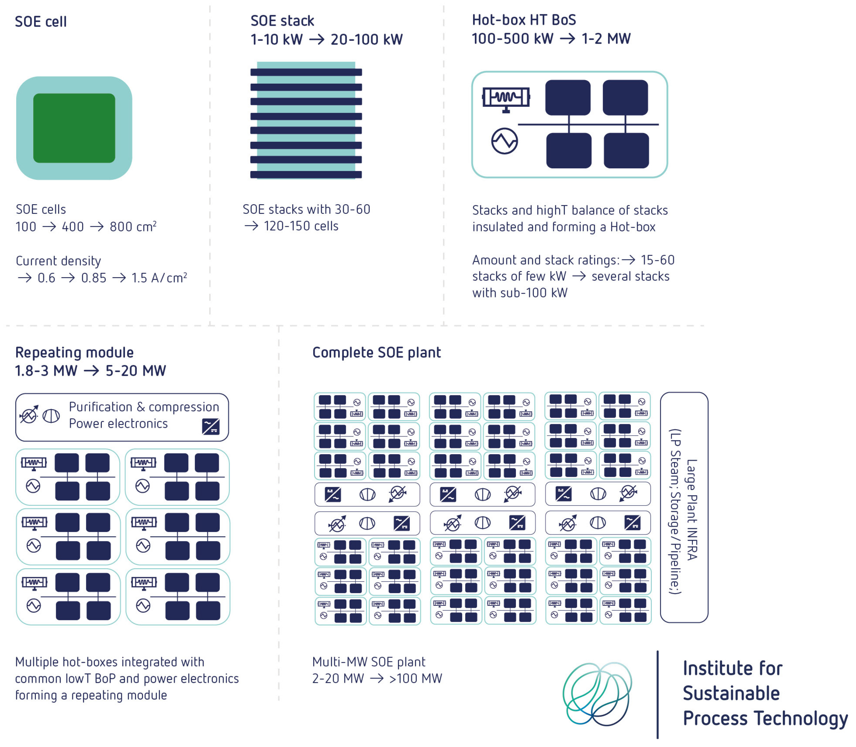
Figure 22 presents a roadmap toward the development of a multi-MW SOEC plant, illustrating the progression from a single cell to a fully scaled system.
It is also mentioned that cost reduction due to technological improvements can be achieved through higher current density, larger manufacturing scale (higher volumes), and an increase in the size of cells, stacks, hotbox, and modules.
3.2. Stable Energy Supply Requirement (Solutions to Integrate with RES)
In the context of the energetic transition, the production of green products is of high relevance for the industrial sector. Electrolysis cells play a crucial role in this shift, and SOEC technology has significant potential to contribute. To ensure that the products can truly be considered “green”, integration with Renewable Energy Sources (RES) is essential. However, this integration presents numerous challenges.
RES are inherently intermittent: wind energy fluctuates depending on wind speed, and solar energy is subject to meteorological conditions; both sources can occasionally drop to zero production. Moreover, current energy storage systems remain limited in capacity and performance, posing an additional obstacle to ensuring a stable and continuous energy supply for SOEC operation.
It affects electrolyzers in two aspects. On the one hand, it needs a constant electricity supply for the electrolysis reaction, in other words, for the stack operation. On the other hand, in the SOEC case, this energy can also be required for heating and steam production feed to the cathode, and that supply must be constant. Otherwise, the stack suffers thermic stress that could degrade its components and move its efficiency away from the optimal point caused by temperature.
Consequently, it is necessary to apply systems that solve those technical challenges.
The system proposed by Khan et al. [
19] consists of using thermal energy storage systems based on molten salts, which have been extensively studied in conjunction with SOEC technology. These systems offer high thermal storage capacity and can reach elevated thermal levels, depending on the type of salt employed. For instance, Khan et al. [
19] use salts with a melting point of 770 °C, and Ficili et al. [
24] use a type of salts that operate in a range of 268–480 °C. Thermal levels only achieve the overheated steam production, and the operating stack temperature (600–900 °C) is obtained by electric heating.
Molten salt circuits are widely used in industry and present a viable solution to mitigate energy supply fluctuations, especially in solar-powered applications. Another option, as previously discussed, is proposed by Liang et al. [
20], who suggest coupling RES with complementary renewable sources that can support the system during periods of low RES availability, such as biomass gasification.
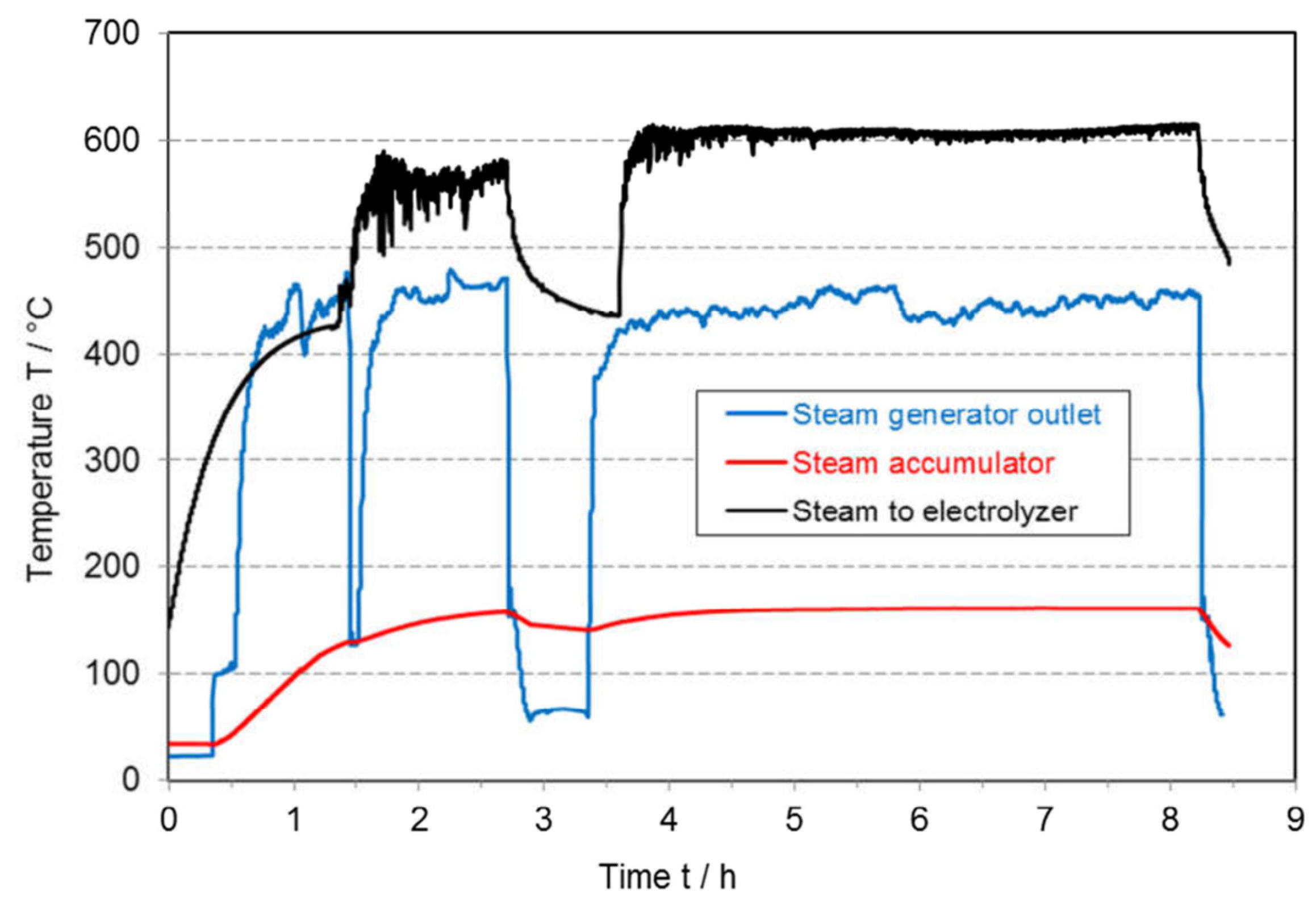
To minimize thermal stress in the cell, the steam supply must also be stable and free of fluctuations. Schiller et al. conducted a laboratory-scale experiment in which an SOEC stack was powered using a solar simulator, while a steam accumulator tank was introduced to buffer supply interruptions. The study demonstrated that, when the steam flow was interrupted for 30 min, the stack temperature declined gradually and within limits, and quickly returned to its operating level once the steam flow resumed, as shown in
Figure 23.
Alternatively, thermo-mechanical energy storage entails a promising option, as previously explained, developed by Qi et al. [
3].
It consists of using liquid CO2 energy storage (LCES), which, in contrast to other types of thermo-mechanical energy storage, has a higher energy density, higher storage durability, and fewer geographic constraints.
LCES is based on a thermodynamic cycle involving compressors, pumps, and turbines, capable of generating electricity, harnessing RES production peaks. In contrast to thermo-chemical storage, it has the advantage of having a higher operational life, exhibits safer operation, and easier integration in industrial processes in which residual energy can also be utilized.
The use of CO2 instead of air or hydrogen itself has the advantage that higher capacity storage tanks can be replaced by small volume buffer tanks. In addition, CO2 is non-toxic, non-flammable, and is easier to bring to supercritical conditions because it maintains a low viscosity. It can be obtained from capture from industrial processes; thus, its utilization is environmentally friendly.
Qi et al. [
3] chose CO
2 liquid storage due to the advantages that it presents.
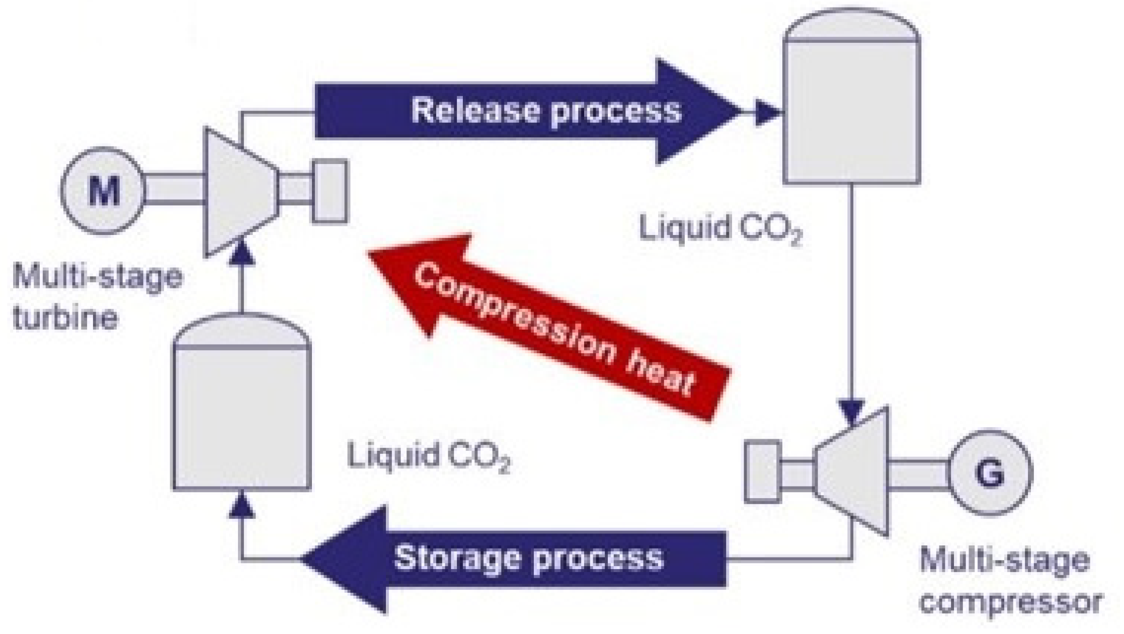
Figure 24 exhibits its configuration.
The cycle has three phases: charge, storage, and generation. In the charge phase, the surplus RES energy is used to compress CO2, which is later cooled with cooling water and stored in a lower temperature and high-pressure tank. When electricity is required during a low-RES production moment, the CO2 is heated with the steam produced during compression cooling, and it is expanded inside a turbine, generating electricity. That system presents an electrical round-trip efficiency (ERTE) of 53.49% and an Energy Storage Density (ESD) of 47.65 kWh/m3.
Thermo-mechanical CO2 storage is an option that can be integrated into processes like PtM or any process that uses CO2 as a reactant. It supposes an adequate solution to integrate RES in the PtM process with SOEC.
3.3. Proton-Conducting Ceramic Electrochemical Cells (PCECs)
Increasing interest is being garnered by Proton-conducting ceramic electrolysis cells (PCECs). Although the materials and durability are less developed than the oxygen-ion conducting SOECs covered in this review, they certainly offer several potential advantages, such as lower operating temperatures, even below 600 °C. This is opening a field for process integration at lower operating temperatures.
The applications of PCECs are focused on energy conversion and on chemical synthesis [
26,
27].
For energy conversion, PCECs are proposed as low-temperature SOFCs (LT-SOFCs) and low-temperature SOECs with operating temperatures below 650 °C, which makes them more suitable for reducing the system costs given the wider availability of materials for the interconnects and seals [
26].
Regarding chemical production, there is a wide range of applications where PCECs can be used, such as hydrogen purification in proton-conducting separation membranes (where hydrogen separation is based on dense proton conductors, driving the flow of hydrogen through the ceramic membrane) or membrane reactors [
26]. An application of a membrane reactor is a proton-conducting membrane that can be used with an external power source to extract hydrogen from the reforming side in the water gas shift reaction used in the reforming of methane or other fuels. This is a growing interest in energy savings and process intensification of methane reforming at low temperature (400–600 °C). Another high-value application is the synthesis of ammonia [
26], where electrochemical synthesis of ammonia using proton-conducting membranes can be used to improve and replace the traditional and high-energy-intensive Haber-Bosch process.
Co-electrolysis applications and electrochemical reduction of CO
2 are also relevant applications for PCECs [
27]. Several species such as CO
2, NOx, N
2, C
2H
4, and others can be utilised in PCECs, resulting in the formation of CO (+H
2O), N
2 (+H
2O), NH
3, or C
2H
6 products [
27] which are highly valuable chemicals for further usage in several industrial processes. Coupled electrochemical conversion of CO
2 and H
22O can occur at temperatures of 500 °C in PCECs as demonstrated by Duan et al. [
28] to produce hydrogen as well as CO and CH4 with high Faradaic efficiencies and high round-trip efficiency (electricity-to-hydrogen-to-electricity) of >75%.
4. Conclusions
SOEC electrolyzers exhibit faster kinetics and higher performance due to their operating temperatures between 700 and 950 °C. This heating requirement does not necessarily imply additional energy expenditure because of the possibility of integrating it into a wide variety of industrial processes.
This review, organized and presented according to the final product, first highlights the diversity of SOEC process integrations. Hydrogen production represents the simplest integration approach, such as the inlet and outlet stream integration proposed by Zhao et al. [
10] or the integration in autothermal reforming processes (Cho et al. [
12]), where a stack with enough power can completely satisfy the ATR oxygen requirements, among other integration strategies.
Integration with solar energy is a recurring theme, and several solutions have been proposed to address its intermittency, including Thermochemical Energy Storage (TCES) using ammonia (Chen et al. [
1], LCES (Qi et al. [
3]), and TES with molten salts (Ali et al. [
18]). These solutions are promising and compatible with SOEC technology, particularly molten salts, which are a well-established and commercially available technology.
Co-electrolysis is a unique capability of SOEC and one of its most interesting possibilities to integrate into methanol and liquid fuels production. Regarding syngas production, it offers the advantage of adjusting the H
2/CO ratio, and the WGS reactor can be replaced by the stack. An et al. [
17] apply these advantages to improve the syngas production efficiency.
The developed critical analysis is exposed in
Table 1,
Table 2,
Table 3 and
Table 4, which collect the most important results from every paper and compare them to provide a global overview of the state of the art. Overall, the results are promising; however, only 3 of the 19 papers present experimental results, and those three highlight challenges such as the need for effective thermal insulation, stable and continuous operation, and degradation of stack components.
When compared with the KPIs presented by Clean Hydrogen Joint Undertaking [
29], SOEC technology still requires significant development and research to meet the 2030 targets.
SOEC electrolyzers are versatile and promising technologies that could form part of the next generation of industrial electrolyzers, contributing to the decarbonization of industry. Nevertheless, substantial technological advances and further experimental data, both at laboratory and industrial scales, are necessary before they can be commercially deployed. As proton-conducting ceramic electrolysis cells (PCECs) continue to be developed, prospects for industrial integration of the technology increase as the reduced operating temperatures make them more prone to be integrated within a wider range of processes. Additionally, integration with Thermal Energy Storage technologies such as molten salts can be further analyzed in order to enable the 24 h operation of SOEC plants coupled with renewable energies based on solar thermal and photovoltaics.

