Abstract
This paper proposes a battery emulator based on a bidirectional non-inverting buck-boost power electronics converter. With the capability of bidirectional operation, it can emulate both charging and discharging processes. The proposed emulator is controlled with the advanced I2 dual current-mode control (I2DCMC) algorithm, combined with a feedforward control, which ensures fast and accurate tracking of the voltage and current characteristics of the batteries. The emulator is universal in terms of the various mathematical models of the batteries, which can be implemented in real time. It has no limitations regarding different battery types. Detailed analysis and the design procedure of the proposed battery emulator are presented. The performances of the emulator are validated with simulation and experimental results for three battery types: polymer Li-ion, conventional Li-ion, and lead–acid battery. Both steady and transient states are analyzed, especially transitions between charging and discharging phases. The possibility of simple time scaling of charging/discharging processes is successfully achieved and demonstrated, which is very important in making tests faster, with preserved battery characteristics. Considering its low-cost and user-friendly operation, the proposed emulator can be a good alternative to the real batteries in experimental tests of different power electronics systems. The prototype, which is developed for the experimental verification of the emulator, is designed for and limited to the research of lower power ratings systems of up to 100 W. It is suitable in education to easily demonstrate the behavior of the batteries in multiple scenarios in controlled laboratory conditions.
1. Introduction
Batteries are energy storage devices which have a very important role in various power electronics applications today, especially in electric vehicles. Among different battery types, lithium-ion (Li-ion) batteries are one of the most promising and increasingly used storage devices in electric vehicles, grid energy storage systems, and other applications because of their numerous advantages, such as light weight, high energy density, no memory effect, and long lifetime [1,2,3]. However, major drawbacks of the Li-ion batteries are their high cost and safety, which limit their usage. Therefore, working with real batteries during laboratory tests of different battery-based systems requires high investment and care [4].
Except for price, there are other inevitable limitations and problems with using real batteries in experimental tests of power electronics systems: impossibility to obtain repeatable results, time-consuming charging/discharging processes, dependence on the ambient factors, necessity for battery maintenance and management, etc. To overcome these problems, in recent years, researchers have proposed different devices which can mimic the behavior of the batteries. These devices are called battery emulators. The output voltage and current of the battery emulator behave the same as the voltage and current of the real battery. Therefore, the battery emulator can entirely replace the real battery or battery pack in laboratories during the experimental prototyping and verification of various battery energy storage systems, which brings numerous benefits. By using the battery emulators, the test conditions can be controlled and repeated, which makes the entire testing process easier. Unlike real batteries, which take a long time to charge and discharge, the battery emulators can be configured with much shorter charging/discharging times. This allows a significant reduction in the research duration. Also, the battery emulators exclude the use of the battery management systems (BMSs), which are especially needed when working with the real Li-ion batteries, primarily because of their safety issues. On the other hand, if the task is to test the BMS itself, it can be easily tested on the battery emulators, because various scenarios can be quickly obtained and demonstrated without the need for time-consuming work with the real batteries [5,6,7,8,9]. Considering the high cost of the batteries, possibility of their damage, need for their replacement, and safety problems, the use of the battery emulators significantly reduces the research costs and improves research safety.
Usually, the commercially available battery emulators are very expensive, hard to purchase and do not meet all the users’ needs, especially in research and development. For these reasons, researchers have proposed many different types of battery emulators in the literature. Some of them are based on commercial programmable power supplies, which are controlled by various control and data acquisition platforms [8,9,10,11,12,13,14,15,16,17,18,19,20,21]. These power supplies often have high prices. They can be programmed to follow the characteristics of the battery models executed in real time, but in terms of their internal hardware and control modularity, they have limited usage. The battery emulators, consisting of different electronic modules, are proposed in [5,6,7,22,23,24,25,26,27]. They are mostly used for BMS validation, so it is not critical for them to have the power ratings of real batteries. Nevertheless, these modules have power amplifiers or regulators at their outputs to adjust the output voltage and current to the necessary real levels. However, the applied amplifiers have limited output voltage and current, which can be insufficient if the emulators are tested as energy sources instead of real batteries.
Among the existing battery emulators, the most suitable are the emulators based on power electronics converters, because of their modularity, scalability, possibility to obtain desirable voltage, and current levels appropriate for the real batteries and battery packs, wide control possibilities, etc. Various converter topologies have been applied: synchronous buck converter [2,28,29]; two-phase [30], three-phase [31,32,33,34,35], four-phase [36,37], six-phase [38], and eight-phase [39] interleaved synchronous buck converter; boost converter [40]; synchronous boost converter [4,41,42]; three-phase interleaved synchronous boost converter [43]; flyback converter [44,45]; cascaded dual-active bridge converter [46]; and other complex combinations of converters [3,47,48,49,50,51]. When using a buck or boost converter as a main power stage of the battery emulator, there is a limitation in its output voltage range, depending on the input voltage. This can be an issue if the emulator needs to have the possibility of implementation of different battery types and packs with various voltage levels. Interleaving, which brings numerous benefits, comes with other issues, such as increased complexity of topology and control structure of the emulator, and smaller efficiency due to the increased number of switching elements. A flyback converter can achieve a larger output voltage range, but it has its own limitations, especially regarding its maximum output power, which is a problem in the application of emulators in higher power systems. Other proposed converters and their combinations increase the complexity of the emulators, specifically their control.
It can be concluded that there is a gap in finding an optimal battery emulator which satisfies all criteria, from the price, complexity, modularity, and application to the working performances. Most of the research from the literature is focused on developing battery emulators of specific battery types, with specific and narrow applications. A more general approach is needed to make the emulator replicate the behavior of different battery types and technologies, in a user-friendly manner, which will extend and adapt its application to wider research areas. Therefore, this is still a very open scientific topic with many challenges to solve. In order to make a cost-effective, simple, and modular battery emulator, with enhanced control features, this paper proposes the battery emulator with a bidirectional non-inverting buck-boost converter as its main power stage. This converter is chosen rather than some other mentioned converters in the literature for several reasons. The first one is its ability to easily achieve a wide output voltage range. By adjusting the duty cycle of its switching signals, it can work in both buck or boost modes, i.e., its output voltage can be smaller or larger than its input voltage. This makes the design of the emulator easier in terms of the modularity criteria, i.e., if the emulator needs to have an option to select different battery types with various voltage levels. The most important reason is the bidirectional operation of the non-inverting buck-boost converter. Unlike synchronous buck or boost converters, which can also work in both directions, the bidirectional non-inverting buck-boost converter has a symmetrical structure. It looks and behaves the same from its input to output, regardless of the energy flow direction. A very important criterion in design of the proposed emulator is a simple converter topology. In comparison to the other implemented, more complex converters in the literature, especially interleaved converters, a simple topology of the bidirectional non-inverting buck-boost converter does not require a complicated switching control, which makes it more suitable than others.
Special attention must be devoted to the control structure of the battery emulator. It must provide precise and fast tracking of the nonlinear voltage characteristics, which are continuously computed in real time from the battery model. The output voltage of the selected bidirectional non-inverting buck-boost converter must accurately follow the calculated referent battery voltage, which is time-varying according to the implemented battery model. Also, the computed referent battery voltage can change much faster if the charging/discharging times of the emulator are scaled, i.e., decreased on purpose, to speed up the testing process. In addition, considering that the emulators are often tested under different profiles of the battery current, especially pulsed currents, the converter’s control must be robust against these load disturbances. In this paper, the advanced I2 dual current-mode control (I2DCMC) method from [52] is applied for the control of the proposed battery emulator. The I2DCMC is selected because it satisfies all the requirements, in terms of necessary stability, accuracy, dynamical response, and robustness.
The main advantages of the proposed battery emulator are as follows:
- Capability of bidirectional operation, which ensures emulation of both charging and discharging phases;
- Generality in terms of the various battery types and models which can be emulated and implemented;
- Excellent accuracy and dynamical properties, thanks to the application of the I2DCMC;
- Modularity in terms of the emulator’s topology, battery model and control structure;
- Capability of charging/discharging time scaling;
- Possibility of rapid control prototyping with user-friendly interface suitable for researchers and especially students, which also provides its application for educational purposes.
This paper is organized as follows. The topology of the proposed battery emulator, with a description of all key blocks, is presented in Section 2. The simulation results of the proposed emulator are presented and discussed in Section 3. Section 4 describes the experimental verification of the emulator, with the corresponding experimental results and discussion. The conclusion is given in Section 5.
2. Topology of the Proposed Battery Emulator
The block-diagram of the proposed battery emulator is shown in Figure 1.
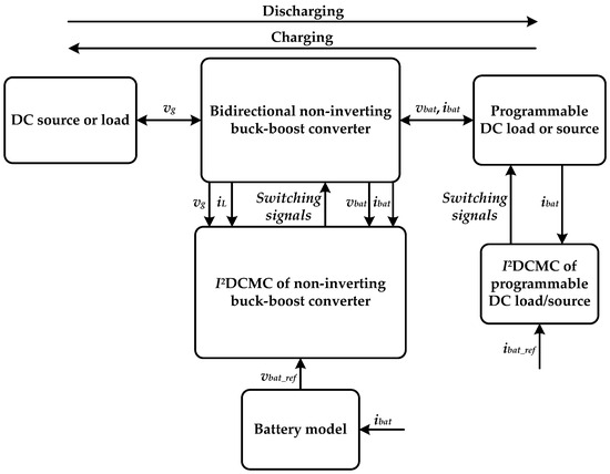
Figure 1.
The block-structure of the proposed battery emulator.
The basic parts from Figure 1 are briefly described in the following subsections.
2.1. Bidirectional Non-Inverting Buck-Boost Converter
The main power stage of the proposed battery emulator is the bidirectional non-inverting buck-boost converter, shown in Figure 2.
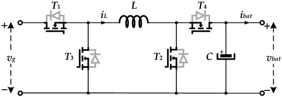
Figure 2.
Topology of the bidirectional non-inverting buck-boost converter.
This converter is symmetrical with respect to the input and output sides. The pairs of power switches (T1, T2) and (T3, T4) are simultaneously controlled with the same switching signals with frequency fs and their inverted values, respectively. When both T1 and T2 are switched on, T3 and T4 are both switched off, and vice versa. Depending on the duty cycle value D of the switching signals, this converter can work in the buck mode, when the output voltage vbat is smaller than the input voltage vg, or in the boost mode, when vbat is larger than vg:
This feature is very useful for the emulation of different battery types and packs with different voltage levels. The output voltage vbat and current ibat represent the emulated battery voltage and current, respectively. In other words, the output of the proposed battery emulator, i.e., the output of the non-inverting buck-boost converter from Figure 2 should behave as the output of the real battery. For that purpose, a proper control structure should be implemented to make the output voltage vbat follow the referent battery voltage vbat_ref, calculated from the battery model. In this paper, the I2DCMC method from [52] is used. The first criterion is to apply current-mode control, because it has numerous advantages over conventional voltage-mode control. The I2DCMC, being advanced current-mode control, is proven to be a good choice for the various types of converters, thanks to its following features: constant switching frequency, stability for all duty cycle values (no subharmonic oscillations in the inductor current iL), zero error between the average value of the inductor current and referent current on each switching period, fast dynamical response, robustness to different disturbances and variations in the converter parameters, simple design procedure, etc. [52].
A key characteristic of the converter from Figure 2 is its possibility of bidirectional operation, which is ensured with the used power switches. When emulating the discharging mode, the current, i.e., energy, flows from the left (input voltage vg) to the right (output voltage vbat). During charging mode, the energy flows in the opposite direction.
2.2. I2DCMC of Non-Inverting Buck-Boost Converter
The structure of the I2DCMC, applied on the proposed battery emulator, is shown in Figure 3.

Figure 3.
The structure of the I2DCMC of non-inverting buck-boost converter.
The I2DCMC method is explained in [52], with the detailed control design procedure. The role of the outer voltage loop compensator Gco(s) is to regulate the output voltage vbat, in accordance with the referent battery voltage vbat_ref. A simple proportional–integral (PI) compensator is applied:
For better dynamical properties, especially for the improvement in the response during battery load changes, i.e., during the changes in the output current ibat, a feedforward (FF) block, proposed in [53], is added to the output of the compensator Gco(s) (Figure 3):
The output of the modified voltage loop represents the referent current iref, which is used as the reference for the inner current loop. The inner current loop compensator Gci(s), together with a set of logical circuits (Figure 3), provides a very accurate and fast regulation of the inductor current iL, which ensures excellent dynamical properties and robustness of the proposed battery emulator. A simple integral (I) compensator is implemented:
Design guidelines for both compensators Gco(s) and Gci(s) are presented in [52]. As proven in [52], the gain value Ki of the compensator Gci(s) is equal to the selected crossover frequency of the inner current loop gain. This means that the transient response time of the inner current loop is inversely proportional to the gain Ki. Therefore, the gain Ki should be large to obtain fast transient response. On the other hand, the outer voltage loop is usually designed to be slower than fast inner current loop. The gain values (kp, ki, Ki) are given in Table 1. In accordance with these values, the settling time of the outer voltage loop is set to approximately 25 ms, while for the inner current loop, it is about 1 ms.

Table 1.
The parameters used in simulations and experiments.
The parameter Ib (Figure 3) represents a constant current offset added to the control signal ic, so the inductor current iL is bounded between the ic + Ib and ic − Ib limits. The bandwidth 2Ib must be larger than the maximum peak-to-peak ripple of the inductor current iL, to ensure stable operation of the converter, without subharmonic oscillations.
2.3. DC Source or Load
The non-inverting buck-boost converter must have its power supply, which is capable of both sourcing (discharging mode) and sinking (charging mode) current, as shown in Figure 4.
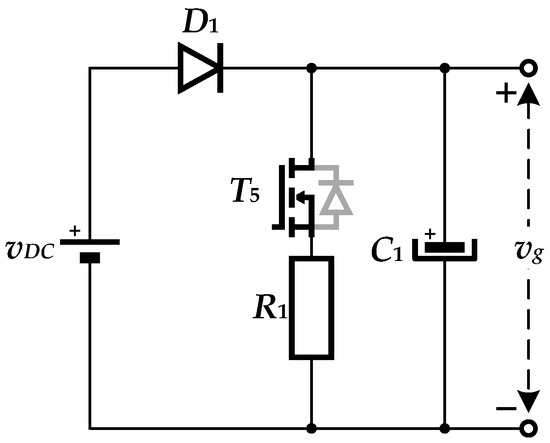
Figure 4.
The power supply of the non-inverting buck-boost converter—DC source or load.
A circuit from Figure 4 is proposed in [4]. During emulation of battery discharging mode, the power switch T5 is switched off, the diode D1 conducts, and the current flows from the DC source vDC to the right, supplying the non-inverting buck-boost converter. Therefore, in discharging mode, the circuit from Figure 4 behaves as the DC source of the non-inverting buck-boost converter. During emulation of charging mode, the power switch T5 is switched on and the current flows from the non-inverting buck-boost converter to the left, through the switch T5 and resistor R1. The diode D1 does not conduct, protecting the DC source vDC from receiving the current. In this way, the circuit from Figure 4 behaves as a load of the non-inverting buck-boost converter during the charging phase.
2.4. Programmable DC Load or Source
As will be explained later, the mathematical model of the battery requires the measured battery current ibat (Figure 1). This battery current, which is the output current of the non-inverting buck-boost converter (Figure 2), is set and controlled by using a programmable DC load shown in Figure 5.
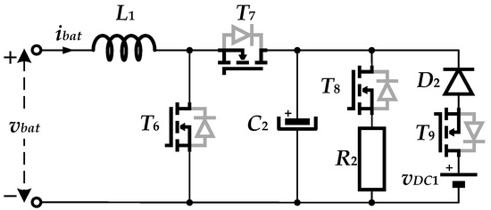
Figure 5.
The programmable DC load of the non-inverting buck-boost converter.
The main part of the circuit from Figure 5 is the bidirectional synchronous buck/boost converter (inductor L1, power switches T6 and T7). In discharging mode, the power switch T8 is switched on, the power switch T9 is switched off, the diode D2 does not conduct, and the circuit from Figure 5 behaves as the active load of the non-inverting buck-boost converter. Since the current ibat flows from the left to the right during discharging mode, the converter from Figure 5 works as the synchronous boost converter, with the load resistance R2 and output capacitance C2. In charging mode, the power switch T8 is switched off, the power switch T9 is switched on, the diode D2 conducts, and the converter from Figure 5 behaves as the synchronous buck converter, with the input DC source vDC1‚ input capacitance C2, and the output voltage vbat. During charging mode, the current ibat flows from the right to the left side, and the circuit from Figure 5 behaves as the DC source of the non-inverting buck-boost converter.
To provide different test cases and profiles of the battery current ibat, the circuit from Figure 5 requires proper control. The battery current ibat is the current through the inductor L1, which enables the application of the I2DCMC, as shown in Figure 6.

Figure 6.
I2DCMC of programmable DC load/source of the non-inverting buck-boost converter.
2.5. I2DCMC of Programmable DC Load/Source
The structure of the I2DCMC, which is used for regulation of the battery current ibat, is given in Figure 6.
The control structure from Figure 6 is same as the one from Figure 3, except that the outer voltage loop is not used in this case, because the referent battery current ibat_ref is directly set by the user. For discharging mode, the referent battery current ibat_ref is positive (the battery current ibat flows from the left to the right), while for charging mode, it is negative (the direction of the battery current ibat is opposite). The proposed I2DCMC ensures very fast and accurate tracking of the given referent current ibat_ref, which means that different profiles, i.e., waveforms of the battery current ibat can be achieved. As for the I2DCMC of the non-inverting buck-boost converter (Figure 3), a simple I compensator is also implemented here:
2.6. Battery Model
The quality and characteristics of the battery emulator very much depend on the mathematical model of the real battery. The battery model needs to be accurate and comprehensive, to approximately match the behavior of the real battery. The modeling of batteries is a very popular scientific topic, with many different proposed approaches. The battery emulator proposed in this paper is universal in terms of the possibility of implementation of different battery models in real time. Therefore, the modeling procedures are not the focus of this paper, nor the comparison with the response of the real batteries. Without loss of generality, three different models of batteries are implemented in this paper: the polymer Li-ion battery model proposed in [54], the conventional Li-ion, and the lead–acid battery model proposed in [55].
2.6.1. Polymer Li-Ion Battery Model
The equivalent electrical circuit of the polymer Li-ion battery model is shown in Figure 7.

Figure 7.
The electrical circuit of the polymer Li-ion battery model, proposed in [54].
The state of charge (SOC) of the proposed battery model from Figure 7 can be determined from the following equation:
The values of all model parameters from Figure 7 are taken from [54]. The values of Ccapacity and Rself-discharge are given in Table 1. Other model parameters are expressed as follows:
The voltages vtransient_S and vtransient_L are the voltages of the capacitors Ctransient_S and Ctransient_L, respectively:
It is obvious from (6)–(15) that the model of the polymer Li-ion battery has single input—the battery current ibat. The output of this model is the referent battery voltage vbat_ref, which is used as the reference for the outer voltage loop compensator in Figure 3.
A very important feature of the proposed battery emulator is the possibility to speed up the charging/discharging process, by a simple multiplication of the battery current ibat in (6) with a scaling factor k (k > 1):
If self-discharge in (17) is neglected, i.e., Rself-discharge = +∞ (open circuit), (17) becomes
When the battery current ibat is constant, the SOC can be obtained from (18) as:
It is obvious from (19) that the slope of the SOC is k-times increased. This means that the SOC will change k-times faster, which results in a faster charging/discharging process. This enables much faster tests of the battery emulator, unlike time-consuming work with real batteries.
2.6.2. Conventional Li-Ion Battery Model
The conventional Li-ion battery model, proposed in [55], is based on a simple electrical circuit, consisting of controlled voltage source and resistor with resistance R, connected in series. The current ibat, which flows through this circuit, represents the battery current, and it controls the value of the voltage source. The output voltage of the circuit vbat_ref can be represented with the following equations [55]:
for discharging, and
for charging. The parameters E0, R, K, Q, A, and B represent battery constant voltage, internal resistance, polarization constant or resistance, battery capacity, amplitude of the exponential zone, and inverted time constant of the exponential zone, respectively. Their values are taken from [55] and given in Table 1. The variable i*bat is the filtered, i.e., average battery current ibat.
The SOC of the conventional Li-ion battery model can be calculated in the following way:
for discharging, and
for charging. This model also has the possibility to scale duration of the charging/discharging process, by using the scaling factor k which multiplies the battery current ibat in (20)–(23), except in part Ribat.
2.6.3. Lead–Acid Battery Model
The model of the lead–acid battery, proposed in [55], is also derived from the same simple electrical circuit described in Section 2.6.2. The only difference in equations for vbat_ref is in the last exponential term with parameters A and B:
for discharging, and
for charging. The term Exp from (24) and (25) represents a hysteresis phenomenon between the charging and discharging of the lead–acid battery, and can be expressed as:
where u = 0 for discharging and u = 1 for charging.
The SOC is calculated with same Equations (22) and (23). The parameters E0, R, K, Q, A, and B have the same meaning as in the previous model, and they are listed in Table 1.
The time scaling of discharging/charging process with the scaling factor k can be achieved in identical ways as described in the previous models.
3. Simulation Results and Discussion
The proposed battery emulator from Figure 1 is modeled and simulated in Matlab/Simulink, to validate its performances. All three described battery models are implemented. The values of all used parameters are given in Table 1.
The implemented simulation model is very complex and requires a lot of computational burden. It would be impossible to perform simulation tests for typical real charging/discharging times (in hours), because the simulations would last enormously long, producing unbearable burden for the computer. For that reason, the charging/discharging time is scaled by using the factor k, which multiplies the battery current in (6), for the polymer Li-ion battery model, in (20)–(23) for the conventional Li-ion battery model, and in (24)–(26) for the lead–acid battery model. For the following simulations tests, k is set to 7500, 20,000, and 40,000 for the polymer Li-ion, conventional Li-ion, and lead–acid battery model, respectively.
3.1. Simulation Results for the Polymer Li-Ion Battery Model
In Figure 8, the battery voltage and current, i.e., the output voltage and current of the proposed battery emulator, are shown for both charging and discharging processes. For a better view of the transient response during charging/discharging, Figure 9 shows only the output voltage for the same test case.
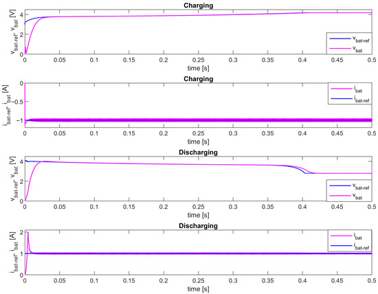
Figure 8.
The output voltage and current of the proposed battery emulator—simulation results (polymer Li-ion battery model).
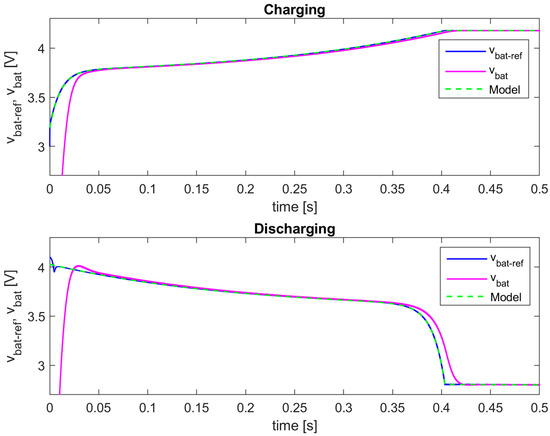
Figure 9.
The output voltage of the proposed battery emulator—simulation results (polymer Li-ion battery model).
The referent battery current ibat_ref is set to 1 A for discharging, and −1 A for charging. It is obvious from Figure 8 that the output current ibat follows the referent current ibat_ref well, thanks to the applied I2DCMC. The current ibat enters a steady state in approximately 10 ms, which is equal to the designed settling time. It has overshoots during transient response of about 13% at the beginning of charging and 98% at the beginning of discharging. This large current overshoot during discharging can be attributed to the simulation start-up, when Simulink components could exhibit unrealistic behavior in a very short period after simulation starts, especially because of algebraic loops and snubber elements.
Since the current ibat flows through the inductor L1 (Figure 5), it contains a small peak-to-peak ripple, which can be neglected. It is worth noting that the average value of the battery current ibat, which is equal to the referent battery current ibat_ref, must be larger than the half of its maximum peak-to-peak ripple in order to maintain continuous conduction mode of the programmable DC load/source. In this case, for the parameters from Table 1, this minimum value is about 0.1 A.
It can be seen, especially from Figure 9, that the output voltage vbat looks as expected, as the typical voltage of the Li-ion batteries, during both charging and discharging. The voltage vbat follows the referent battery voltage vbat_ref well, which is calculated from the model. There is a tracking delay of approximately 25 ms at the beginning of the charging and end of the discharging process, which is expected and equal to the transient response time of the designed outer voltage loop compensator Gco(s), as discussed in Section 2.2. This compensator can be easily made faster to minimize these delays. However, that is unnecessary because it is fast enough for more realistic, much larger charging/discharging times, so these delays during transient responses will be negligibly small.
If only the battery model is simulated separately, without all other components from Figure 1, the input battery current is manually set as a constant (ibat = ±1 A) and the output battery voltage of the model is computed (green dashed line on Figure 9, denoted as “Model”). In the complete model of the entire battery emulator, the battery model receives the battery current ibat, which is the output current of the non-inverting buck-boost converter. As shown in Figure 8, the current ibat has overshoots during transient responses and needs about 10 ms to reach the steady states (±1 A). However, it is obvious from Figure 9 that these transient responses have a very small influence on the accuracy and dynamics of the proposed emulator, since vbat_ref, which is calculated using such current ibat, is precisely matched with the output battery voltage obtained from the battery model with constant input. Only at the beginning of discharging, there is about 10% over/undershoot in vbat_ref because of the already mentioned battery current overshoot.
To verify the behavior of the proposed battery emulator during step changes in the battery current, the following simulation test is conducted. The referent battery current ibat_ref is changed from −1 A (charging) to 1 A (discharging), and again to −1 A (charging). The duration of the current pulse, which is equal to 0.3 s, is chosen on purpose to avoid full charging and discharging. The simulation results are given in Figure 10.
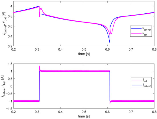
Figure 10.
The output voltage and current of the proposed battery emulator (step changes in the referent battery current ibat_ref: −1 A→1 A→−1 A)—simulation results (polymer Li-ion battery model).
It can be concluded from Figure 10 that the proposed battery emulator has a very good transient response in terms of both output voltage and current, which can be attributed to the implemented I2DCMC, especially the added FF block (Figure 3). The battery voltage vbat has an expected settling time of around 25 ms. The battery current ibat also has an expected settling time of around 10 ms, while its overshoots are 32% (charging-to-discharging transient) and 15% (discharging-to-charging transient).
3.2. Simulation Results for the Conventional Li-Ion Battery Model
The tests presented in Section 3.1 are also performed for the battery emulator with the conventional Li-ion battery model. The simulation results are shown in Figure 11 and Figure 12.
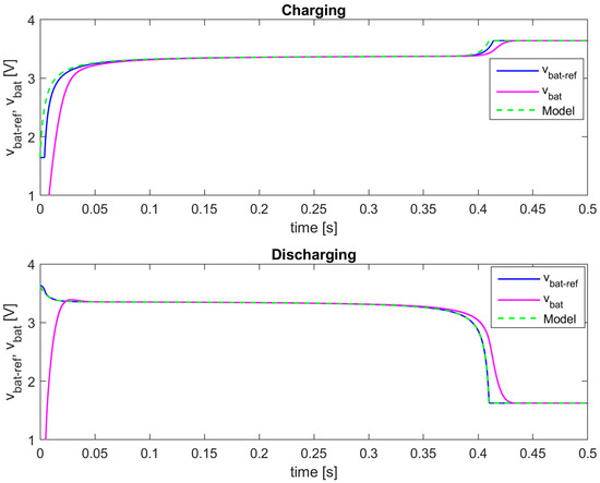
Figure 11.
The output voltage of the proposed battery emulator—simulation results (conventional Li-ion battery model).
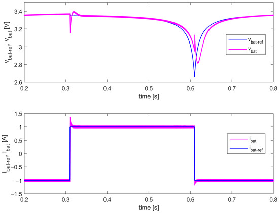
Figure 12.
The output voltage and current of the proposed battery emulator (step changes in the referent battery current ibat_ref: −1 A→1 A→−1 A)—simulation results (conventional Li-ion battery model).
Similar conclusions can be derived from the given results, as in the case of the battery emulator with the polymer Li-ion battery model. This confirms the modularity of the proposed battery emulator in terms of the implemented battery type and model.
3.3. Simulation Results for the Lead–Acid Battery Model
The simulation results for the emulator with the lead–acid battery model are shown in Figure 13 and Figure 14, under the same test scenarios from Section 3.1 and Section 3.2.
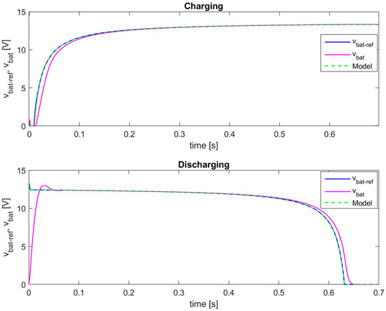
Figure 13.
The output voltage of the proposed battery emulator—simulation results (lead–acid battery model).
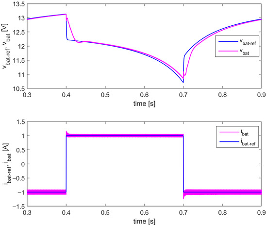
Figure 14.
The output voltage and current of the proposed battery emulator (step changes in the referent battery current ibat_ref: −1 A→1 A→−1 A)—simulation results (lead–acid battery model).
It is important to note that in the case of the lead–acid battery model, the value of the DC source voltage vDC1 of the programmable DC load/source is set to 20 V instead of 10 V used for the previous two models. The reason is, in steady state, when the lead–acid battery is fully charged, or at the beginning of discharging (Figure 13), the battery voltage vbat is approximately 13.34 V. A topology of the programmable DC load/source (Figure 5) requires that the voltage vbat is always smaller than vDC1.
It can be concluded that the proposed battery emulator successfully replicates the output voltage of the lead–acid battery model, in both test cases. The applied I2DCMC ensures a zero steady-state error in both battery voltage and current, with expected transient responses in accordance with the selected control parameters.
The results from Figure 13 confirm the benefits of using bidirectional non-inverting buck-boost converter. Its input voltage vDC is equal to 6 V during discharging, and the emulated battery voltage vbat goes up to 13.34 V, which is more than three times larger than the maximum emulated battery voltage for two previous models. Therefore, this converter is suitable for implementation of various battery models with different output voltage ranges.
4. Experimental Results and Discussion
After simulation analysis, the proposed battery emulator is tested experimentally on the developed prototype, shown in Figure 15.
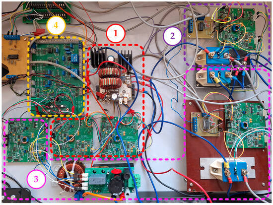
Figure 15.
The experimental prototype of the proposed battery emulator: 1—Bidirectional non-inverting buck-boost converter with gate drivers; 2—DC source or load; 3—Programmable DC load or source; and 4—Electronic module for measurements and I2DCMC of non-inverting buck-boost converter and programmable DC load/source.
The switching part of the bidirectional non-inverting buck-boost converter (power switches T1–T4 from Figure 2) consists of four power MOSFETs IRF540N (International Rectifier, El Segundo, CA, USA) (100 V, 33 A), which satisfy defined voltage and current levels, and nominal power of the converter of about 100 W.
The bidirectional synchronous buck/boost converter from Figure 5 is made from commercially available SPM-HB (Taraz, Rawalpindi, Pakistan) half-bridge power module, with power MOSFETs ST21N90K5 (STMicroelectronics, Geneva, Switzerland) (900 V, 18.5 A).
The power switches T5 (Figure 4), T8 and T9 (Figure 5) are implemented with SIMOPAC modules BSM 191F 4012 (Siemens, Munich, Germany). A diode module DSEI2X31-06C (IXYS, Milpitas, CA, USA) (600 V, 30 A) is used for diodes D1 (Figure 4) and D2 (Figure 5).
One of the main requirements in the design of the experimental setup is galvanic isolation between the converter and control electronics. For that purpose, a two-channel galvanically isolated gate driver is developed, which can independently control the output channels, but also synchronously control the power switches in half-bridge, with a programmable “dead time”. The drivers have approximately 0.6 µs turn on/off delay.
All the voltage and current measurements are achieved with galvanic isolation between the converter and control part of the emulator. The input and output voltage of the non-inverting buck-boost converter are measured using optocouplers IL300 (Vishay, Malvern, PA, USA). The inductor and output current are measured with HX 10-NP (LEM, Meyrin, Switzerland) current transducers, having open loop Hall effect technology.
All three mathematical models of the batteries, presented in Section 2.6, are implemented in real time in Matlab/Simulink environment, by using Real Time Windows Target (MathWorks, Matlab R2023b, Natick, MA, USA) library and built-in MF624 (Humusoft, Prague, Czech Republic) data acquisition card. The input and output voltage, and output current of the non-inverting buck-boost converter vg, vbat, and ibat, respectively, are measured and fed to the 14-bit A/D converter inputs of the MF624 card. The A/D converters have approximately 2 µs conversion time and ±10 V input voltage range. The MF624 card enables real-time operation of the implemented battery models in Simulink. The Simulink model calculates in real time the referent battery voltage vbat_ref, which is used for the outer voltage loop of I2DCMC (Figure 3). The outer voltage compensator, combined with the feedforward control, is implemented in this same Simulink model. The generated referent current iref, together with the current offset Ib, are exported from the Simulink model via 14-bit D/A converter outputs (±10 V output voltage range, 10 V/µs slew rate) of the MF624 card and fed to the electronic module for implementation of the inner current loop of I2DCMC. The referent battery current ibat_ref (Figure 6) is manually set by the user within the same Simulink model and exported from the MF624 card, together with the current offset Ib1. They are used by another channel of the electronic module for implementation of I2DCMC of programmable DC load/source. The sample time of the Simulink model is set to 50 µs.
Experimental waveforms in the following subsections are recorded with Tektronix MSO 2014 (100 MHz, 1 GS/s) oscilloscope (Beaverton, OR, USA).
4.1. Experimental Results for the Polymer Li-Ion Battery Model
In the first test case, the scaling factor k is set to 500. The experimental results for charging at ibat = −1 A and discharging at ibat = 1 A, are shown in Figure 16.
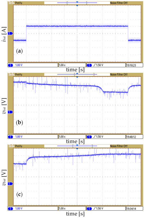
Figure 16.
The experimental results for k = 500: (a) the output current ibat; (b) the output voltage vbat during discharging; and (c) the output voltage vbat during charging (polymer Li-ion battery model).
It is obvious from Figure 16a that the output current ibat follows accurately and fast the step changes in the referent battery current from −1 A to 1 A, and vice versa. The interval of these changes is enough for both charging and discharging processes to be finished. The output voltage vbat for the entire discharging and charging process is shown in Figure 16b and Figure 16c, respectively. The output voltage vbat has expected waveforms typical to the Li-ion batteries during charging/discharging. It can be noticed in Figure 16b,c that the output voltage vbat has constant portions, which correspond to fully charged and discharged thresholds.
In the second test case, the scaling factor k is set to 7500, as in the simulations. The experimental results are shown in Figure 17, for the step changes in the referent battery current from −1 A (charging) to 1 A (discharging), and vice versa. The interval of the current pulse is the same as in the simulations, and equal to 0.3 s. The goal is to test the dynamical behavior of the proposed battery emulator during switching between charging and discharging, and vice versa, when there is not enough time to perform full charging/discharging processes.
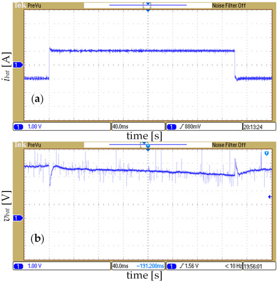
Figure 17.
The experimental results for k = 7500: (a) the output current ibat and (b) the output voltage vbat (polymer Li-ion battery model).
The experimental waveform of the battery current ibat (Figure 17a) is very similar to the simulation waveform from Figure 10. The current overshoots are about 40% and 20% for charging to discharging transient and vice versa, respectively. In the experimental waveform of the battery voltage vbat (Figure 17b), there are larger undershoots and overshoots in the moments of step changes in the battery current, in comparison to the simulation waveform from Figure 10. This difference can be attributed to the nonidealities (real parameters) in the components of the prototype of the battery emulator, which are not considered in the simulation model, such as switching delays, delays and errors introduced with measurement and filtering of the voltages and currents, printed circuit board trace parasitic elements, losses in semiconductor switches, inductors, capacitors, etc.
4.2. Experimental Results for the Conventional Li-Ion Battery Model
The same experimental tests are conducted for the conventional Li-ion battery model. First, the scaling factor k is set to 20,000/15 = 1.33 × 10³. The experimental results for charging at ibat = −1 A and discharging at ibat = 1 A, are shown in Figure 18.
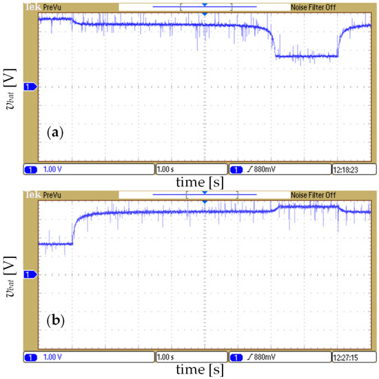
Figure 18.
The experimental results for k = 20,000/15: (a) the output voltage vbat during discharging and (b) the output voltage vbat during charging (conventional Li-ion battery model).
Similar conclusions can be made for the waveforms from Figure 18, as in the case of the polymer Li-ion battery.
In the second test case, the scaling factor k is set to 20,000, like in the simulation tests. The experimental waveforms of the output voltage vbat are shown in Figure 19. They are similar to the corresponding simulation waveforms from Figure 12, but they have larger under/overshoots during the transients.
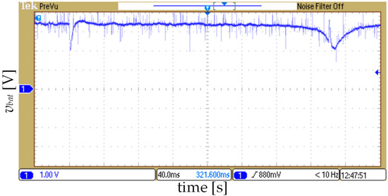
Figure 19.
The experimental results for k = 20,000: The output voltage vbat for the step changes in the referent battery current ibat_ref (−1 A→1 A→−1 A at every 0.3 s)—conventional Li-ion battery model.
It can be concluded, as in the simulation verification, that the modularity of the proposed battery emulator in terms of the implemented battery type and model, is also experimentally validated.
4.3. Experimental Results for the Lead–Acid Battery Model
Following exact testing procedure for the previous two battery models, the battery emulator based on the lead–acid battery model is experimentally verified. In the first test case, the scaling factor k is set to 4000. The corresponding experimental waveforms for charging (ibat = −1 A) and discharging (ibat = 1 A), are shown in Figure 20.
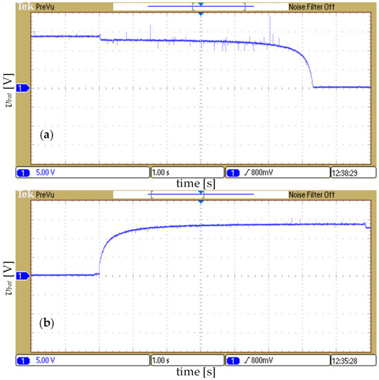
Figure 20.
The experimental results for k = 4000: (a) the output voltage vbat during discharging and (b) the output voltage vbat during charging (lead–acid battery model).
In the second test case, the scaling factor k is set to 40,000, as in the simulations. The experimental results are shown in Figure 21.
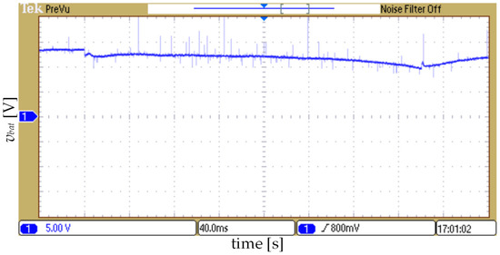
Figure 21.
The experimental results for k = 40,000: the output voltage vbat for the step changes in the referent battery current ibat_ref (−1 A→1 A→−1 A at every 0.3 s)—lead–acid battery model.
4.4. Comparison Between Experimental and Simulation Results
It is mandatory that both simulation and experimental verification of the proposed battery emulator produce well-matched results, i.e., waveforms of the battery voltage and current, under same test conditions. A high quality of the simulation model, which matches reality well, is crucial in the proper design of the emulator’s control structure and for the reliable validation. The following graphs compare the corresponding experimental and simulation responses for all three battery types considered. The given experimental waveforms (blue lines) from Figure 22, Figure 23 and Figure 24 represent the real-time measured values of the output voltage vbat, obtained from the A/D converters of the MF624 card. It is evident that the experimental and simulation waveforms are well matched for all three implemented battery models, with negligible static errors. This also confirms the benefits of using I2DCMC, which guarantees precise and robust regulation of the battery voltage and current.
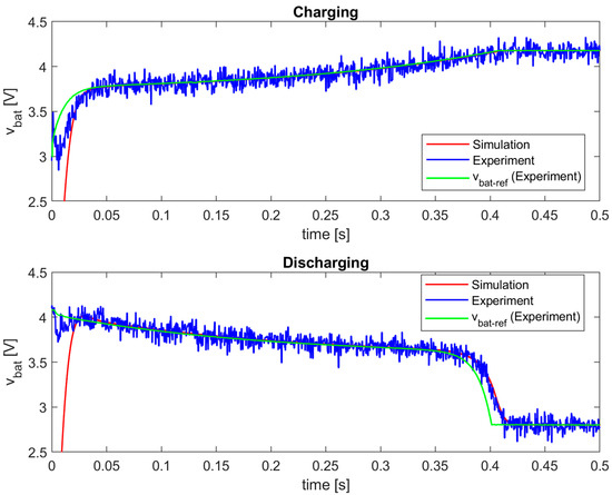
Figure 22.
Comparison between experimental and simulation results for the polymer Li-ion battery model (k = 7500).
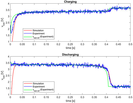
Figure 23.
Comparison between experimental and simulation results for the conventional Li-ion battery model (k = 20,000).
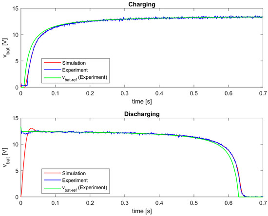
Figure 24.
Comparison between experimental and simulation results for the lead–acid battery model (k = 40,000).
5. Conclusions
In this paper, the battery emulator, which is based on the current-mode controlled bidirectional non-inverting buck-boost converter, is proposed, with a detailed description of all its parts. The performances of the proposed battery emulator are successfully validated with both simulation and experimental tests, for three different battery models.
The main contributions of this paper refer to the achieved excellent characteristics and advantages of the proposed battery emulator:
- Excellent tracking accuracy and dynamics—the implemented I2DCMC ensures precise and fast tracking of the referent battery voltage and current;
- Possibility of charging/discharging time scaling—using simple scaling factor k that speeds up the change in SOC, and thus increasing the charging/discharging velocity, which enables much easier and faster laboratory tests of the battery-based systems;
- Modularity in terms of the implemented real-time battery model—various mathematical models of the batteries can be easily configured and applied in real time, in a user-friendly Matlab/Simulink environment;
- Modularity in terms of the implemented battery types—in this paper, the polymer Li-ion, conventional Li-ion, and lead–acid batteries are considered as examples, although other types of batteries with different voltage and current levels can be implemented, thanks to the applied non-inverting buck-boost converter, which can work with wide range of input/output voltages and currents;
- Modularity in terms of the hardware topology—all hardware parts of the emulator can be easily configured and modified, including the controller, i.e., instead of a used MF624 control board, other control platforms can be implemented.
One of the main goals of this paper is to develop a new, user-friendly, and cost-effective platform for battery emulation, with reliable advanced control. The proposed battery emulator successfully provides the desired voltage and current values and waveforms, in accordance with the battery models implemented in real time. The next task for future works will be to develop the model and identify its parameters for the specific real battery, to implement that model in the proposed battery emulator, and to compare the experimental response from the real battery and emulator.
Author Contributions
Conceptualization, S.L. (Srđan Lale) and M.B.; methodology, S.L. (Srđan Lale); software, S.L. (Srđan Lale); validation, S.L. (Srđan Lale), M.B., S.L. (Slobodan Lubura), B.P. and M.I.; formal analysis, S.L. (Srđan Lale) and M.B.; investigation, S.L. (Srđan Lale); resources, S.L. (Srđan Lale); data curation, S.L. (Srđan Lale), M.B., S.L. (Slobodan Lubura), B.P. and M.I.; writing—original draft preparation, S.L. (Srđan Lale); writing—review and editing, M.B., S.L. (Slobodan Lubura), B.P. and M.I.; visualization, S.L. (Srđan Lale); supervision, M.B.; project administration, S.L. (Srđan Lale); funding acquisition, M.B. All authors have read and agreed to the published version of the manuscript.
Funding
This research received no external funding.
Data Availability Statement
The data presented in this study are available on request from the corresponding author.
Conflicts of Interest
The authors declare no conflicts of interest.
References
- Tie, S.F.; Tan, C.W. A review of energy sources and energy management system in electric vehicles. Renew. Sustain. Energy Rev. 2013, 20, 82–102. [Google Scholar] [CrossRef]
- Luna, M.; Di Piazza, M.C.; La Tona, G.; Accetta, A.; Pucci, M. Exploiting dynamic modeling, parameter identification, and power electronics to implement a non-dissipative Li-ion battery hardware emulator. Math. Comput. Simul. 2021, 183, 48–65. [Google Scholar]
- Boles, J.D.; Ma, Y.; Wang, J.; Osipov, D.; Tolbert, L.M.; Wang, F. Converter-based emulation of battery energy storage systems (BESS) for grid applications. IEEE Trans. Ind. Appl. 2019, 55, 4020–4032. [Google Scholar] [CrossRef]
- Mesbahi, T.; Rizoug, N.; Bartholomeus, P.; Le Moigne, P. Li-Ion battery emulator for electric vehicle applications. In Proceedings of the IEEE Vehicle Power and Propulsion Conference (VPPC), Beijing, China, 15–18 October 2013. [Google Scholar]
- Dai, H.; Zhang, X.; Wei, X.; Sun, Z.; Wang, J.; Hu, F. Cell-BMS validation with a hardware-in-the-loop simulation of lithium-ion battery cells for electric vehicles. Int. J. Electr. Power Energy Syst. 2013, 52, 174–184. [Google Scholar]
- Buccolini, L.; Orcioni, S.; Longhi, S.; Conti, M. Cell battery emulator for hardware-in-the-loop BMS test. In Proceedings of the IEEE International Conference on Environment and Electrical Engineering and IEEE Industrial and Commercial Power Systems Europe (EEEIC/I&CPS Europe), Palermo, Italy, 12–15 June 2018. [Google Scholar]
- Messier, P.; LeBel, F.; Rouleau, J.; Trovao, J.P.F. Multi-cell emulation for battery management system validation. In Proceedings of the IEEE Vehicle Power and Propulsion Conference (VPPC), Chicago, IL, USA, 27–30 August 2018. [Google Scholar]
- Dai, H.; Wei, X.; Sun, Z.; Wang, J. A hardware-in-the-loop system for development of automotive battery management system. In Measuring Technology and Mechatronics Automation in Electrical Engineering, Lecture Notes in Electrical Engineering; Hou, Z., Ed.; Springer: New York, NY, USA, 2012; Volume 135, pp. 27–36. [Google Scholar]
- Wu, S.; Zou, Y.; Peng, X.; Li, H. Hardware-in-loop verification of battery management system with RT-LAB. In Proceedings of the IEEE Conference and Expo Transportation Electrification Asia-Pacific (ITEC Asia-Pacific), Beijing, China, 31 August–3 September 2014. [Google Scholar]
- Thanheiser, A.; Kohler, T.P.; Bertram, C.; Herzog, H.-G. Battery emulation considering thermal behavior. In Proceedings of the IEEE Vehicle Power and Propulsion Conference, Chicago, IL, USA, 6–9 September 2011. [Google Scholar]
- Seitl, C. Development and Implementation of a Battery Emulator for Power Hardware-In-The-Loop Simulations. Master’s Thesis, Vienna University of Technology, Vienna, Austria, 2014. [Google Scholar]
- Shekoofa, O.; Pouryaie, N.; Sohrabzadeh, K.; Rezvani, M. Improving the EGSE of power subsystem by design and development of a battery emulator for space applications. In Proceedings of the 4th International Conference on Recent Advances in Space Technologies, Istanbul, Turkey, 11–13 June 2009. [Google Scholar]
- Daniil, N.; Drury, D. Improving the stability of the battery emulator—Pulsed current load interface in a Power Hardware-in-the-Loop Simulation. In Proceedings of the IECON 2016—42nd Annual Conference of the IEEE Industrial Electronics Society, Florence, Italy, 23–26 October 2016. [Google Scholar]
- Daniil, N.; Drury, D. Investigation and validation of methods to implement a two-quadrant battery emulator for power Hardware-in-the-Loop Simulation. In Proceedings of the IECON 2016—42nd Annual Conference of the IEEE Industrial Electronics Society, Florence, Italy, 23–26 October 2016. [Google Scholar]
- Varais, A.; Roboam, X.; Lacressonnière, F.; Bru, E.; Roux, N. Reduced Scale PHIL Emulation Concepts Applied to Power Conversion Systems With Battery Storage. IEEE Trans. Ind. Electron. 2021, 68, 3973–3981. [Google Scholar]
- Cabello, J.M.; Roboam, X.; Junco, S.; Bru, E.; Lacressonniere, F. Scaling Electrochemical Battery Models for Time-Accelerated and Size-Scaled Experiments on Test-Benches. IEEE Trans. Power Syst. 2017, 32, 4233–4240. [Google Scholar]
- Fan, B.; Zhang, B.; Shi, Y.; Chang, Y. A high-fidelity lithium-ion battery emulator for electric vehicle application. Sci. Rep. 2024, 14, 19742. [Google Scholar] [CrossRef] [PubMed]
- Peskar, J.; Downey, A.R.J.; Khan, J.; Booth, K. Progress Towards a Coupled Electro-thermo Battery Emulator. In Proceedings of the IEEE Electric Ship Technologies Symposium (ESTS), Alexandria, VA, USA, 1–4 August 2023. [Google Scholar]
- Halivni, B.; Beniaminson, D.; Maman, L.; Yankovich, A.; Evzelman, M.; Peretz, M. Scalable High-Power Battery Emulator for Power Hardware-in-the-Loop Applications. In Proceedings of the IEEE 24th Workshop on Control and Modeling for Power Electronics (COMPEL), 25–28 June 2023. [Google Scholar]
- Madden, C.; Peskar, J.; Sado, K.; Downey, A.; Khan, J. Electro-Thermal Hardware-in-the-Loop Battery Emulator for Shipboard Systems Testing. In Proceedings of the IEEE Electric Ship Technologies Symposium (ESTS), Alexandria, VA, USA, 5–8 August 2025. [Google Scholar]
- Lacressonnière, F.; Varais, A.; Roboam, X.; Bru, E.; Mullins, T. Scale electro-thermal model of a lithium-ion battery for time-accelerated experiments in a hardware in the loop process. J. Energy Storage 2021, 39, 102576. [Google Scholar] [CrossRef]
- Chou, P.H.; Park, C.; Park, J.; Pham, K.; Liu, J. B#: A battery emulator and power profiling instrument. In Proceedings of the International Symposium on Low Power Electronics and Design, Seoul, Republic of Korea, 25–27 August 2003. [Google Scholar]
- Vicidomini, G.; Petrone, G.; Monmasson, E.; Spagnuolo, G. FPGA based implementation of a sliding-mode observer for battery state of charge estimation. In Proceedings of the IEEE 26th International Symposium on Industrial Electronics (ISIE), Edinburgh, UK, 19–21 June 2017. [Google Scholar]
- Rienzo, R.D.; Roncella, R.; Morello, R.; Baronti, F.; Saletti, R. Low-cost modular battery emulator for battery management system testing. In Proceedings of the IEEE International Conference on Industrial Electronics for Sustainable Energy Systems (IESES), Hamilton, New Zealand, 31 January–2 February 2018. [Google Scholar]
- Verani, A.; Di Rienzo, R.; Nicodemo, N.; Baronti, F.; Roncella, R.; Saletti, R. Modular Battery Emulator for Development and Functional Testing of Battery Management Systems: Hardware Design and Characterization. Electronics 2023, 12, 1232. [Google Scholar] [CrossRef]
- Verani, A.; Rienzo, R.D.; Nicodemo, N.; Baronti, F.; Roncella, R.; Saletti, R. Open Hardware/Software Modular Battery Emulator for Battery Management Systems Development and Functional Testing. IEEE Access 2024, 12, 84488–84497. [Google Scholar] [CrossRef]
- Santoni, F.; De Angelis, A.; Moschitta, A.; Carbone, P. Digital Impedance Emulator for Battery Measurement System Calibration. Sensors 2021, 21, 7377. [Google Scholar] [CrossRef]
- Högerl, T.; Buberger, J.; Schwitzgebel, F.; Obkricher, L.; Estaller, J.; Hohenegger, M.; Kersten, A.; Kuder, M.; Eckerle, R.; Weyh, T. Battery Emulation for Battery Modular Multilevel Management (BM3) Converters and Reconfigurable Batteries with Series, Parallel and Bypass Function. In Proceedings of the IEEE International Conference on Environment and Electrical Engineering and IEEE Industrial and Commercial Power Systems Europe (EEEIC/I&CPS Europe), Bari, Italy, 7–10 September 2021. [Google Scholar]
- Jassim, H.M.; Ziuzev, A.M.; Mudrov, M.V. Power hardware-in-loop emulation of a battery for charging systems and grid applications. Bull. Tomsk. Polytech. Univ. Geo Assets Eng. 2024, 335, 200–211. [Google Scholar] [CrossRef]
- Michalczuk, M.; Ufnalski, B.; Grzesiak, L.M.; Rumniak, P. Power converter-based electrochemical battery emulator. Prz. Elektrotechniczny 2014, 90, 18–22. [Google Scholar]
- König, O.; Hametner, C.; Prochart, G.; Jakubek, S. Battery Emulation for Power-HIL Using Local Model Networks and Robust Impedance Control. IEEE Trans. Ind. Electron. 2014, 61, 943–955. [Google Scholar]
- König, O.; Jakubek, S.; Prochart, G. Battery impedance emulation for hybrid and electric powertrain testing. In Proceedings of the IEEE Vehicle Power and Propulsion Conference, Seoul, Republic of Korea, 9–12 October 2012. [Google Scholar]
- Wasserburger, A.; König, O.; Jakubek, S. Estimation and compensation of DC-Link voltage disturbances in a DC–DC converter for battery emulation. Int. J. Control. 2020, 93, 922–933. [Google Scholar]
- König, O.; Gregorčič, G.; Jakubek, S. Model predictive control of a DC–DC converter for battery emulation. Control. Eng. Pract. 2013, 21, 428–440. [Google Scholar]
- Thanheiser, A.; Meyer, W.; Buecherl, D.; Herzog, H.-G. Design and investigation of a modular battery simulator system. In Proceedings of the IEEE Vehicle Power and Propulsion Conference, Dearborn, MI, USA, 7–11 September 2009. [Google Scholar]
- Zauner, M.; Mandl, P.; Hametner, C.; König, O.; Jakubek, S. Flatness-Based Discrete-Time Control of a Battery Emulator Driving a Constant Power Load. IEEE J. Emerg. Sel. Top. Power Electron. 2021, 9, 6864–6874. [Google Scholar]
- Kleutgens, P.H.J.; Hagemann, L.; Meißen, A.; Mortimer, B.J.; De Doncker, R.W. A power hardware-in-the-loop test bench for emulation of test scenarios and mission profiles for high-power DC charging stations. Elektrotech. Inftech. 2025, 142, 30–41. [Google Scholar] [CrossRef]
- Kulsangcharoen, P.; Rashed, M.; Klumpner, C.; De, D.; Patel, C.; Asher, G.; Chen, G.Z. Evaluation of a digitally controlled power electronic emulator for supercapattery. In Proceedings of the 6th IET International Conference on Power Electronics, Machines and Drives (PEMD 2012), Bristol, UK, 27–29 March 2012. [Google Scholar]
- Baumhöfer, T.; Waag, W.; Sauer, D.U. Specialized battery emulator for automotive electrical systems. In Proceedings of the IEEE Vehicle Power and Propulsion Conference, Lille, France, 1–3 September 2010. [Google Scholar]
- Farag, S.; Lerman, C.; Lineykin, S.; Kuperman, A. Off-the-Shelf Power Supply-Based Battery/Supercapacitor Emulator for Charger Functionality Testing. IEEE Trans. Transp. Electrif. 2016, 2, 129–139. [Google Scholar]
- Hidalgo-León, R.; Jácome-Ruiz, P.; Almeida-Pazmiño, G.; Urquizo-Guevara, J.; Soriano-Idrovo, G. A Survey on Technologies to Implement Battery Emulators Based on DC/DC Power Converters. In Proceedings of the 14th LACCEI International Multi-Conference for Engineering, Education, and Technology: “Engineering Innovations for Global Sustainability”, San José, Costa Rica, 20–22 July 2016. [Google Scholar]
- Mesbahi, T.; Rizoug, N.; Khenfri, F.; Bartholomeüs, P.; Le Moigne, P. Dynamical modelling and emulation of Li-ion batteries–supercapacitors hybrid power supply for electric vehicle applications. IET Electr. Syst. Transp. 2017, 7, 161–169. [Google Scholar] [CrossRef]
- Hidalgo-León, R.; Urquizo, J.; Litardo, J.; Muñoz-Jadán, Y.; Singh, P.; Wu, J. Simulation of battery discharge emulator using power electronics device with cascaded P-I control. In Proceedings of the IEEE International Conference on Industrial Technology (ICIT), Buenos Aires, Argentina, 26–28 February 2020. [Google Scholar]
- Thale, S.; Wandhare, R.; Agarwal, V. A novel low cost portable integrated solar PV, fuel cell and battery emulator with fast tracking algorithm. In Proceedings of the IEEE 40th Photovoltaic Specialist Conference (PVSC), Denver, CO, USA, 8–13 June 2014. [Google Scholar]
- Santos León, A.I.; Peña Acosta, Á.A.; Trujillo Rodríguez, C.L.; Santamaría Piedrahita, F. Design and Implementation of a Lead-Acid Battery Emulator. J. Eng. Sci. Technol. Rev. 2020, 13, 172–180. [Google Scholar] [CrossRef]
- Mishra, S.; Tamballa, S.; Pallantala, M.; Raju, S.; Mohan, N. Cascaded Dual-Active Bridge Cell Based Partial Power Converter for Battery Emulation. In Proceedings of the 20th Workshop on Control and Modeling for Power Electronics (COMPEL), Toronto, ON, Canada, 17–20 June 2019. [Google Scholar]
- Dingrui, L. Development of a Converter-Based Testing Platform and Battery Energy Storage System (BESS) Emulator for Microgrid Controller Function Evaluation. Master’s Thesis, University of Tennessee, Knoxville, TN, USA, 2021. [Google Scholar]
- Wang, Q.; Wei, X.Z.; Dai, H.F. Hardware-in-Loop Test Platform for Electric Vehicle Cell Battery Management System. Appl. Mech. Mater. 2010, 29–32, 2398–2403. [Google Scholar] [CrossRef]
- Spataru, S.; Martins, J.; Stroe, D.-I.; Sera, D. Test Platform for Photovoltaic Systems with Integrated Battery Energy Storage Applications. In Proceedings of the IEEE 7th World Conference on Photovoltaic Energy Conversion (WCPEC) (A Joint Conference of 45th IEEE PVSC, 28th PVSEC & 34th EU PVSEC), Waikoloa, HI, USA, 10–15 June 2018. [Google Scholar]
- Filho, P.S.N.; Silveira, J.P.C.; Neto, P.J.d.S.; de Paula, M.V.; Barros, T.A.d.S.; Filho, E.R. Modeling and Experimental Evaluation of Energy Storage Emulator for Microgrids Application. IEEE J. Emerg. Sel. Top. Power Electron. 2021, 9, 6662–6670. [Google Scholar] [CrossRef]
- Li, R.; Ji, Y.; Fu, Y.; Hu, B.; Hu, H. Design and implementation of a parametric battery emulator based on a power converter. IET Electr. Power Appl. 2022, 16, 1300–1316. [Google Scholar] [CrossRef]
- Lale, S.; Šoja, M.; Lubura, S.; Mančić, D. Application of I2 technique on dual current mode control of power electronics converters. Electr. Eng. 2018, 100, 1761–1772. [Google Scholar] [CrossRef]
- Redl, R.; Sokal, N.O. Near-optimum dynamic regulation of DC-DC converters using feed-forward of output current and input voltage with current-mode control. IEEE Trans. Power Electron. 1986, PE-1, 181–192. [Google Scholar] [CrossRef]
- Chen, M.; Rincon-Mora, G.A. Accurate electrical battery model capable of predicting runtime and I-V performance. IEEE Trans. Energy Convers. 2006, 21, 504–511. [Google Scholar] [CrossRef]
- Tremblay, O.; Dessaint, L.A. Experimental validation of a battery dynamic model for ev applications. World Electr. Veh. J. 2009, 3, 289–298. [Google Scholar] [CrossRef]
Disclaimer/Publisher’s Note: The statements, opinions and data contained in all publications are solely those of the individual author(s) and contributor(s) and not of MDPI and/or the editor(s). MDPI and/or the editor(s) disclaim responsibility for any injury to people or property resulting from any ideas, methods, instructions or products referred to in the content. |
© 2025 by the authors. Licensee MDPI, Basel, Switzerland. This article is an open access article distributed under the terms and conditions of the Creative Commons Attribution (CC BY) license (https://creativecommons.org/licenses/by/4.0/).