Abstract
To tackle the inefficiencies in 3D mine tunnel modeling and the tedious task of drawing centerlines, this study introduces a faster method for generating centerlines using CAD secondary development. Starting with the tunnel centerline, the research then dives into techniques for creating detailed 3D tunnel models. The team first broke down the steps and logic behind tunnel modeling, designing a 3D tunnel framework and its data structure—complete with key geometric components like traverse points, junctions, nodes, and centerlines. By refining older centerline drawing techniques, they built a CAD-powered tool that slashes time and effort. The study also harnessed advanced algorithms, such as surface fitting and curve lofting, to swiftly model tricky tunnel sections like curves and crossings. This method fixes common problems like warped or incomplete surfaces in linked tunnel models, delivering precise and lifelike 3D scenes for VR-based mining safety drills and simulations.
1. Introduction
In recent years, as the coal industry has embraced smarter, greener, and higher-quality development, VR technology—especially digital and visualization tools—has seen a surge in applications [1,2]. In the mining industry, VR is commonly employed to simulate accidents and disasters, facilitate training, and conduct emergency drills [3]. At the heart of this digital transformation is the need for precise 3D models of underground tunnels, which are essential for visualizing mine operations [4,5]. This has led researchers to explore ways to create these models quickly and accurately.
For instance, Li et al. [6] developed a method for 3D tunnel modeling using BIM and GIS. They used GIS to map out tunnel centerlines and BIM to process data, employing Boolean operations to handle complex tunnel intersections. Zhu et al. [7] addressed the geometric challenges of various tunnel types—straight, inclined, and vertical—by developing equations for key points. Utilizing Python 3.0 and Blender 2.73, they constructed 3D models for inclined tunnels and complex intersections. Li et al. [8] focused on issues like centerline construction and tunnel cross-sections, using Dynamo to automate the modeling process. Zhao et al. [9] introduced a method that uses virtual guide points and angular bisectors to model tunnels with varying shapes seamlessly. Li et al. [10] extended AutoCAD 2014’s capabilities using VBA, implementing algorithms such as planar extrusion, Boolean operations, and Delaunay triangulation to efficiently construct 3D roadway and surface models for the Xingshan Iron Mine. However, AutoCAD has limitations in rendering complex materials, which makes it difficult to achieve the high-precision visual effects required for detailed visualization.
Today, the most popular approach to 3D tunnel modeling in mining is the cross-section centerline method. This involves drawing centerlines based on guide points and then building the 3D model. However, this method faces several challenges: guide point data are often messy, making manual centerline drawing laborious, and guide points are frequently absent at intersections and turns in mining plans. Given that CAD is the primary software in the coal industry, enhancing its capabilities through secondary development is a logical step to streamline this process.
Additionally, many existing tunnel modeling systems rely on commercial software like 3Dmine 2012.12. While these tools are fast and produce solid models, they are not easily customizable for specific VR-based training and emergency drill needs. In the realm of 3D model representation, technologies such as BIM and WebGL offer significant advantages, but Unity3D 2021.1.0b11 stands out in VR training and accident simulation thanks to its robust 3D editing capabilities, superior graphics, and strong VR/AR support.
With this in mind, the author used C# to script a solution, leveraging mine ventilation diagrams and mining plans as data sources. By enhancing CAD through secondary development, they enabled the rapid sketching of tunnel centerlines. At the same time, they built a 3D tunnel model editor on Unity3D, aiming to support VR-based mine training and drills with a more efficient and tailored approach.
2. Methods
2.1. Basic Principles of Rapid Model Construction
In mining or ventilation system diagrams, tunnels are often packed with survey data. These measurements, collected during excavation, include the 2D coordinates and elevations of traverse points-key references for mapping underground spatial relationships.
When it comes to building 3D tunnel models, three main techniques stand out as follows: the centerline-section method, regular grid method, and 3D point cloud method. The centerline-section approach simplifies tunnels into centerlines and cross-sections. By connecting traverse points to form centerlines and adding cross-sectional details at each node (using interpolation or predefined rules), it creates smooth 3D tunnel surfaces. The other two methods, however, depend on technology like laser scanners or millimeter-wave radars to gather 3D point clouds for modeling [10,11]. But underground environments—with dim lighting, poor textures, and heavy dust—make these methods costly and slow. That is why the centerline-section method remains the go-to for quick 3D tunnel modeling.
Figure 1 shows how traverse points sketch out centerlines, creating a spatial network. To simplify data handling, these points are split into two types: junction points (where tunnels meet or end) and intermediate nodes (marking slope shifts along the tunnel). Here is the breakdown of a 3D tunnel model’s building blocks: (1) Traverse points: Survey markers spaced along tunnels, storing 3D location data (X/Y coordinates + elevation). (2) Junction points: Tunnel endpoints or crossings. For clear connections, intersecting tunnels share one junction point. (3) Intermediate nodes: Non-junction markers highlighting slope changes. More nodes mean a more realistic wavy tunnel model. (4) Tunnel centerlines: The tunnel’s “spine” in 2D plan view, including floor heights. Their arrangement shapes the entire tunnel network.
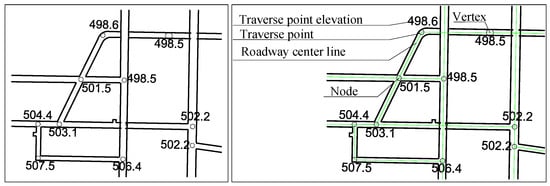
Figure 1.
Schematic diagram of the roadway centerline network topology.
2.2. System Development Architecture
Based on the cross-section centerline modeling approach, we split the 3D roadway modeling system into two key components: a CAD-based tool for fast centerline extraction and a Unity3D-powered roadway editor. The centerline extraction module has two layers—front-end interaction and data storage. The program is developed within the Visual Studio 2022 development environment. The front end uses WPF technology to construct a visual operation interface, enabling user interaction and data acquisition. The back end employs the C# programming language in conjunction with the NET Framework for the secondary development of CAD, achieving the calculation and drawing of the tunnel centerline.
And the editor handles data management, 3D model computations, labeling, and user interaction:
- Data handling: The system reads DXF files, stores centerline data, and manages 3D model files.
- Model calculations: It computes cross-section key points from roadway parameters and applies special logic to bends and intersections.
- Labels and annotations: Users can tag roadways with names, lengths, slopes, and compass orientations directly on the 3D model.
- Interactive features: The interface supports zooming, panning, rotating, and virtual walkthroughs of the roadway network.
The above functions are implemented by developing scripts with the C# programming language, leveraging the UI system and graphics rendering technology of the Unity3D platform.
Here is how the system works:
- First, the centerline tool sketches the roadway layout and exports it as a DXF file.
- Next, the Unity3D editor imports this file and instantly generates a 3D model with default parameters.
- Users can then tweak any roadway’s name, dimensions, or textures (like ground and wall materials), with changes updating live. For realism, the system offers authentic mine-style textures.
2.3. Rapid Extraction of Tunnel Centerlines Using CAD-Based Technology
The acquisition of roadway centerlines is a crucial step in 3D roadway modeling. Traditional manual methods for drawing roadway centerlines involve the following steps: (1) Using CAD Commands: Based on the 3D topological relationships between roadways, the ‘line’ or ‘3dpoly’ command in CAD is used to sequentially connect roadway survey points, forming the centerline. The Z-coordinates are then assigned one by one according to elevation data from the plan view. (2) Using Polylines and Data Export: Alternatively, a 2D polyline is first drawn in the drawing to represent the roadway centerline. The ‘list’ command is then used to export the survey data, and attributes such as elevation and intersection connectivity are assigned in Excel [12]. Both methods are highly labor-intensive and time-consuming. Additionally, not all node positions have corresponding survey points or elevation parameters, further complicating the centerline extraction process. To enable rapid centerline generation, this study developed a CAD plugin using the C# programming language. Figure 2 shows the interactive interface of the roadway centerline extraction program.
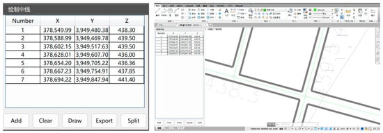
Figure 2.
CAD-based roadway centerline extraction program.
The program’s editing functions for roadway centerlines are primarily as follows:
- Adding Survey Points: Users can directly select the coordinates and elevation labels of survey points from CAD drawings, eliminating the need for tedious manual input. The entered survey point data are displayed in a list. To prevent users from manually defining connections between nodes, the program allows only sequential input of nodes along a single roadway at a time. Clicking “Draw” automatically generates the centerline for the current roadway.
- Clearing Survey Point Data: Users can clear the list of survey points to prepare for entering data for the next roadway.
- Automatic Elevation Interpolation: For nodes without elevation parameters along a roadway, the program automatically calculates elevations using linear interpolation based on existing node elevations.
For any two points in 3D space, P1 (x1, y1, z1) and P2 (x2, y2, z2), the coordinates of an intermediate point P(t) can be determined using linear interpolation with the formula:
P(t) = (1 − t) P1 + tP2 = ((1 − t)x1 + tx2, (1 − t) y1 + ty2, (1 − t) z1 + tz2)
Here, t is a parameter between 0 and 1. When t = 0, P(t) = P1; when t = 1, P(t) = P2.
- Intersection Handling: If two roadways intersect without a shared node, the segment splitting algorithm is applied to split all centerlines at their intersection points. This ensures that any intersection between two roadways occurs at an endpoint of their centerlines, guaranteeing that crossing points exist and share a common node.
The pseudocode for splitting roadway centerlines is as shown in Algorithm 1:
| Algorithm 1 Pseudo-code for roadway segmentation. |
| Input: Input line segment set S = {{x1, y1, z1},{x2, y2, z2},…,{xN, yN, zN}} Output: Split line segment set S′ 1: Initialize S′ ⇐ S 2: for each line segment {xi, yi, zi}∈S do 3: Let the set of intersection points on line li be pts 4: for each line segment {xj, yj, zj}∈ S and i≠j do 5: Calculate the intersection point mi between line segments li and lj 6: if li intersects with lj and the intersection point mi is not on the endpoint of li then 7: Remove li from S’ 8: Add mi to pts 9: end if 10: end for 11: if pts.count>0 then 12: Sort pts by the distance from the starting point of li 13: Split the current line segment into new segments set{startpointi,pts[0]},{pts[0], pts[1]}...{[pts[count −1],endpointi} 14: Add the new segments to S’ 15: end if 16: end for 17: return S’ |
- Export Centerlines: Finally, after completing the centerline drawing, the user can click the “Export” button to export the roadway centerline as a DXF file.
3. Results and Discussion
3.1. Three-Dimensional Modeling of a Single Roadway Based on Unity3D
The construction process of complex 3D roadway models can be broken down into two main steps: the creation of individual roadway segments and the handling of intersection points.
From a spatial perspective, individual roadways can be categorized into horizontal, inclined, and vertical types. However, from a geometric modeling standpoint, the algorithms for constructing these three types share no fundamental differences. Underground roadways serve various functional purposes, and their design parameters vary accordingly, resulting in diverse cross-sectional shapes. Common cross-sectional profiles include circular arches, three-centered arches, trapezoidal, and rectangular designs.
For arched roadways, whether circular or three-centered, only three parameters are needed to define their cross-sectional outline: roadway width (W), roadway height (H), and arch height (F), as shown in Figure 3a,b.

Figure 3.
Types of roadway Cross-Sections ((a) Circular arch roadway; (b) Three-centered arch roadway; (c) Trapezoidal roadway).
The parameters of a trapezoidal roadway cross-section include the following: the base width, roadway height, left wall inclination angle, and right wall inclination angle. When both the left and right wall inclination angles are 90°, the cross-section becomes rectangular, as shown in Figure 3c.
Regarding the 3D modeling process of circular-arched roadway cross-sections, extensive prior research exists. Since trapezoidal and rectangular cross-sections are relatively straightforward, they will not be elaborated on further in this paper.
Taking the three-centered arch modeling process as an example, the construction of its 3D model is explained below.
As shown in Figure 4, point O1 is the center of the top arch of the three-centered arch roadway, while O2 and O3 are the centers of the arch ends. B1, B2, and T0–T3 are characteristic points of the roadway cross-section. Let W denote the roadway width, H the rib height, F the arch height, R the top arch radius, and r the end arch radius. For commonly used three-centered arches in roadway engineering, it is generally required that F < W/2. Let (x0, y0, z0) and (x1, y1, z1) represent the coordinates of the first (P0) and second (P1) traverse points along the roadway centerline, respectively, with Δx = x1 − x0, Δy = y1 − y0, and Δz = z1 − z0.
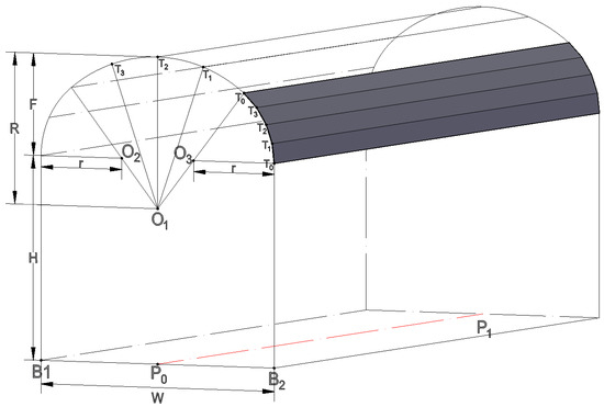
Figure 4.
Wireframe model of a three-centered arch roadway.
Based on the characteristics of a three-centered arch, the following holds true for any such arch:
Assuming that , , the coordinate calculation formula for point B1 can be readily derived as follows:
To calculate the coordinates of B2, simply change −W/2 to W/2 in the above formula.
The central angle of the side arc for a three-centered arch:
Central Angle of the Arc:
In computer graphics, circular arcs are typically drawn using straight-line approximation, where the arc is divided into multiple small segments connected together to approximate the curve. Let (m) represent the number of equal divisions for each arc segment of a three-centered arch, and (n) denote the counterclockwise index of the current feature point being calculated (starting from 0). The coordinates of point (Tn) on the three-centered arch can then be computed using the following formula:
The formula calculates the coordinates of point Tn on the minor arc at the arch end as follows:
When calculating the coordinates of point Tn on the great arc of a vaulted ceiling:
3.2. Processing of Roadway Turning Point Models Based on Unity3D
During the process of tunnel modeling, the winding and undulating shape of the tunnel makes the handling of inflection points and slope transitions a key focus. When using Unity3D to process these features, simply constructing two separate tunnel segments based on the centerline and then joining them often leads to issues such as model fractures or missing surfaces at the inflection points, as illustrated in Figure 5.
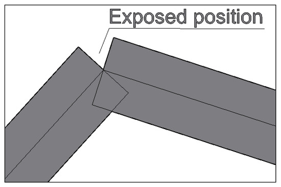
Figure 5.
Before processing the inflection point of the roadway.
To address this issue, some scholars proposed rotating one cross-section of the roadway by γ/2 (where γ is the angle between the two roadway sections at the turning point) to create the intersecting cross-section. However, the author observed that this approach causes the roadway model to exhibit a gradual narrowing of width at turning points and a progressive reduction in height at gradient change points, thereby compromising model accuracy.
In response, a new method for handling roadway turning points and gradient change points is proposed, with the following key steps:
- Using the roadway centerline and basic parameters, calculate the left/right sides and cross-section models of the two roadways. At their intersection, determine the meeting points of the two roadways’ sides.
- Using the line connecting these two points as the base, maintain the original roadway height and arch height to construct an arched cross-section, which serves as the intersecting cross-section for both roadways.
- As illustrated in Figure 6, employ a curve lofting algorithm to connect the three cross-sections, completing the processing of the roadway turning point.
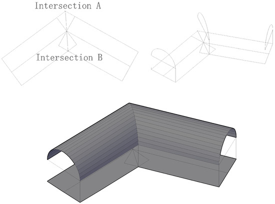 Figure 6. Schematic diagram of the roadway inflection point modeling process.
The lofting algorithm is a commonly used method in CAD for creating 3D models. It generates three-dimensional solids or surfaces by interpolating between multiple cross-sectional profiles [13].
3.3. Cross-Roadway Modeling Method Based on Unity3D
Underground mine tunnels are characterized by numerous inflection points, gradient changes, and frequent intersections with other tunnels. These intersections can be categorized into two types based on their cross-sectional shapes: equal-section and unequal-section crossings [14]. Additionally, depending on the number of intersecting tunnels, common configurations include T-shaped, cross-shaped, and Y-shaped intersections. Without proper treatment of these intersection points, surface gaps may occur [15]. Using equal-section tunnel intersections as an example, we will explain the modeling algorithms by analyzing the geometric characteristics of different intersection configurations.
3.3.1. T-Shaped Intersection Tunnel
Figure 7 illustrates a T-shaped intersecting tunnel, where O1O2 and OO3 represent the centerlines of the two crossing tunnels. The modeling process for this T-junction is as follows:
- (1)
- Determine Intersection Points: Calculate the intersection points A and C where the left and right walls of tunnel segment OO3 meet the left wall of tunnel O1O2, as well as points B and D where they intersect the right wall.
- (2)
- Construct Arch Sections: Using line segments AB and CD as bases, build arched tunnel cross-sections based on the tunnel height and arch rise. Retain only the arched tops corresponding to segments BO and DO.
- (3)
- Segment the T-Junction: With EF as the base, construct another arched cross-section, preserving only the OE segment of the arch. This divides the T-junction into three parts: MNBOE, GHDOE, and QPDOB.
- (4)
- Generate Surface Mesh: Apply a lofting algorithm to connect: ①Arch surface OE with GO1 and MO2; ② Arch surface OD with HO1 and PO3; ③Arch surface OB with NO2 and QO3. This creates quadrilateral surface meshes, forming the 3D model of the T-junction. The resulting intersection demonstrates smooth connectivity and seamless splicing, as shown in the figure.

Figure 7.
T-shaped intersection roadway model processing process.
3.3.2. Cross-Shaped Intersecting Tunnels
The modeling algorithm for cross-shaped intersecting roadways follows a similar principle to the T-type design, with one key difference: it constructs roadway cross-sections along the diagonals of the intersection area ABCD formed by the left and right walls of the two roadways [16]. This division splits the roadway into four distinct sections: AFECO, AGHDO, DPQBO, and BNMCO. Finally, a lofting algorithm is employed to generate the 3D surface model of the roadway structure, as shown in Figure 8.

Figure 8.
Processing procedure of the Cross-Shaped intersection roadway model.
3.3.3. Y-Shaped Intersection Tunnel
Similarly, for Y-shaped intersecting roadways, as shown in Figure 9, the modeling procedure is as follows:
- (1)
- Calculate the intersection points A, B, and C between the sidewalls of the three roadways. Using twice the lengths of OA, OB, and OC as the base edges while maintaining the original roadway height and arch height, construct arched cross-sections, retaining only half of each arch crown.
- (2)
- Divide the roadway into three segments—AMNCO, AEFBO, and BQPCO—based on the three arched cross-sections. Finally, employ a lofting algorithm to generate the 3D surface model of the Y-shaped roadway.

Figure 9.
Processing procedure of the Y-Shaped intersection tunnel model.
3.4. Field Applications
The Shanxi Baoli Pingshan Coal Mine covers a mining area of 4.4 km2 with an annual production capacity of 900,000 tons and is classified as a coal and gas outburst mine. It adopts a development method using main and auxiliary inclined shafts.
Based on the ventilation system diagram provided by the mine, the roadway centerlines were plotted using CAD 2014 software with specialized roadway alignment tools, as illustrated in Figure 10 (where the green lines denote the centerlines). Field investigations identified three primary cross-sectional shapes of excavated roadways: circular, arched, and trapezoidal [17,18]. In rock tunnels, permanent support typically involves a combination of bolt, shotcrete, and mesh reinforcement, whereas coal tunnels primarily utilize an integrated system of bolts, mesh, beams, and cables.
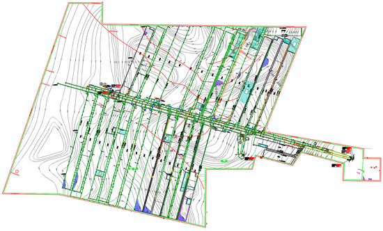
Figure 10.
Roadway centerline of Pingshan Coal Mine.
The roadway centerlines were exported as DXF files and imported into a specialized roadway modeling system. After configuring the cross-sectional parameters and material properties, a 3D roadway model was generated, comprising a total of 1671 processed roadways. The modeling results are presented in Figure 11, Figure 12 and Figure 13.
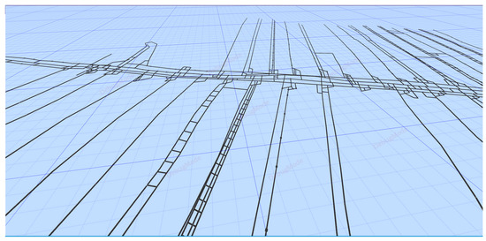
Figure 11.
Three-Dimensional modeling effect of Pingshan Coal Mine roadway.
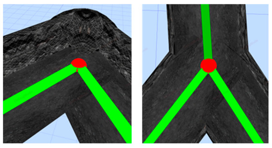
Figure 12.
Corner point effect in tunnel modeling.
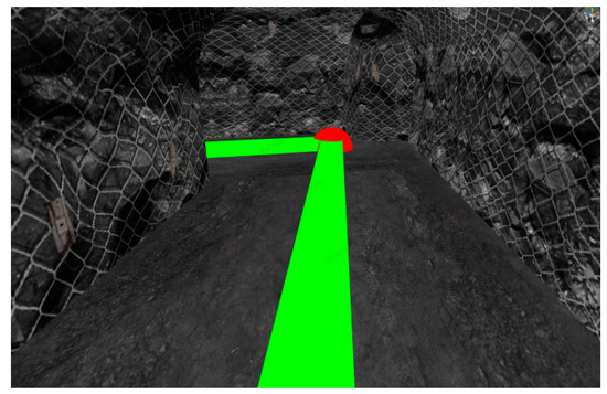
Figure 13.
Interior rendering of the tunnel model.
3.5. Limitations and Prospects
While this study has made significant progress in developing a 3D roadway modeling system, providing a foundational model for VR-based mine training simulations, several limitations remain, primarily in the following areas:
- (1)
- Smooth Transitions at Curved Turns: The current approach for handling curved sections in underground roadways involves adding additional survey points and using straight-line segments to approximate the curve [19]. However, this method results in visually noticeable edges, failing to achieve a smooth transition in the 3D model at curved turns. This discrepancy from actual roadway conditions underscores the need for future research to explore more advanced curve-fitting algorithms.
- (2)
- Modeling Complex Cross-Sections: Further research and refinement are necessary to accurately model roadways with intricate cross-sectional shapes, such as horseshoe profiles, to enhance both the accuracy and realism of the models.
4. Conclusions
This study conducts preliminary research on 3D tunnel modeling based on CAD and Unity3D. The developed system enables the rapid drawing of tunnel centerlines, the construction of 3D models for various tunnel cross-sections, and visual representation of multiple wall and ground materials. Field application results demonstrate the method’s advantages in tunnel modeling through the following aspects:
- (1)
- By leveraging CAD secondary development and employing interpolation algorithms, this method facilitates the rapid generation of roadway centerlines. Compared to traditional manual drawing techniques, it substantially reduces the workload involved in preliminary data processing for roadway modeling.
- (2)
- The parametric tunnel modeling approach employs surface fitting and curve lofting algorithms to construct 3D tunnel models, accurately representing geometric topology at inflection points, slope transitions, and intersections while effectively resolving surface penetration issues in the models.
- (3)
- The tunnel editor developed on the Unity3D platform facilitates the rapid application of various textures to tunnel floors and walls. Compared to traditional modeling methods in AutoCAD, the resulting tunnel models exhibit significantly more realistic visual effects. Unlike mainstream mining modeling software such as BIM and 3DMine, Unity3D-generated models offer cross-platform compatibility, enabling seamless integration into scenarios like VR-based mine safety training. This capability provides strong support for advancing intelligent mine rescue training and simulation systems.
Author Contributions
Methodology, Y.Y. and Y.S.; Software, Y.W.; Investigation, Y.S. and Y.W.; Resources, Y.Y.; Writing—original draft, Y.S.; Writing—review & editing, Y.S. and Y.W.; Supervision, Y.W. All authors have read and agreed to the published version of the manuscript.
Funding
This research was funded by Shenhua Coal Branch Technology Innovation Project (Research on Virtual-Real Hybrid Emergency Drill Technology for Large-Space Multi-Person Collaboration in Mine Fires) and the Tiandi Technology Co., Ltd. Technology Innovation and Entrepreneurship Fund Special Funding Project (2024-TD-ZD023-01).
Data Availability Statement
The original contributions presented in this study are included in the article. Further inquiries can be directed to the corresponding author.
Conflicts of Interest
Author Yingbing Yang was employed by the CCTEG Chongqing Research Institute. The remaining authors declare that the research was conducted in the absence of any commercial or financial relationships that could be construed as a potential conflict of interest.
Correction Statement
This article has been republished with the order of the existing affiliations changed. This change does not affect the scientific content of the article.
References
- Li, M.; Mao, S.; Zhao, M. Research progress and prospects of coal mine intelligent geological guarantee systems. Coal Sci. Technol. 2023, 51, 334–348. [Google Scholar] [CrossRef]
- Qiang, L.; Yanling, W.; Owusu, A.B. A modified Ester-branched thickener for rheology and wettability during CO2 fracturing for improved fracturing property. Environ. Sci. Pollut. Res. 2019, 26, 20787–20797. [Google Scholar] [CrossRef] [PubMed]
- Plavšić, J.; Mišković, I. VR-based digital twin for remote monitoring of mining equipment: Architecture and a case study. Virtual Real. Intell. Hardw. 2024, 6, 100–112. [Google Scholar] [CrossRef]
- Wang, T.; Zhang, T.; Cheng, L. Research and Application of 3D Geology and Roadway Modeling in Coal Mines. Energy Energy Conserv. 2024, 6, 322–324. [Google Scholar] [CrossRef]
- Chen, D.; Pang, N.; Nie, W.; Feng, J.; Kan, J.; Zhang, J. Classification denoising and 3D reconstruction of roadway point clouds. Coal Geol. Exp. 2025, 53, 54–64. [Google Scholar] [CrossRef]
- Li, M.; Kang, J.; Liu, H.; Li, Z.; Liu, X.; Zhu, Q.; Xiao, B. Study on parametric 3D modeling technology of mine roadway based on BIM and GIS. Coal Sci. Technol. 2022, 50, 25–35. [Google Scholar] [CrossRef]
- Zhu, Q.; Zhang, Z.; Liang, J.; Liu, X.; Gu, L.; Zhong, L. Fast generation method of 3D mine roadway model and its application. China Saf. Sci. J. 2022, 32, 48–57. [Google Scholar] [CrossRef]
- Li, W.; Jiao, Y.H.; Qiu, L.; Zhang, X.X.; Ren, D.J. Parametric Modeling of Mine Roadway Based on Dynamo. Met. Mine 2022, 555, 63–70. [Google Scholar] [CrossRef]
- Zhao, L.; Zhang, Y.; Liu, G. Study and Application of 3D Mine Roadway Parametric Modeling Method. Met. Mine 2024, 188–195. [Google Scholar] [CrossRef]
- Li, J.; Li, J.; Lu, J.; Cheng, X. Construction of Three-dimensional Development Model of Underground Mine Based on AutoCAD. Min. Eng. 2021, 19, 29–32. [Google Scholar] [CrossRef]
- Xue, X.; Qin, Y.; Yang, X.; Yue, J.; Guo, Y.; Mao, Q.; Wang, C.; Zhang, X. Digital modeling optimization method of coal mine roadway based on attention mechanism and generative adversarial network. J. China Univ. Min. Technol. 2025, 54, 304–315. [Google Scholar] [CrossRef]
- Li, Q.; Cheng, Y.; Zhang, H.; Yan, C.; Liu, Y. Simulating the effect of hydrate dissociation on wellhead stability during oil and gas development in deepwater. J. Ocean Univ. China 2018, 17, 35–45. [Google Scholar] [CrossRef]
- Liu, B.; Cui, H.; Liu, R.; Su, Y.; Xue, X. A self-adaptive smoothing modeling method for tunnel nodes based on centerline topology relationship. J. Shandong Univ. Sci. Technol. (Nat. Sci.) 2024, 43, 67–73. [Google Scholar] [CrossRef]
- Huang, M.; Zhang, Y.; Sheng, G.; Li, J. Study on the Automatic Modeling of 3D Pipe Network. Geomat. World 2016, 23, 55–61. [Google Scholar]
- Zhang, H.; Mao, S.; Li, M. A Coal Mine Excavation Tunnels Modeling Method Based on Point Clouds. Appl. Sci. 2024, 14, 9454. [Google Scholar] [CrossRef]
- Wang, L. Modeling method of underground roadway intersection processing based on binary space partition tree. Saf. Coal Mines 2022, 53, 138–143. [Google Scholar] [CrossRef]
- Li, Q.; Li, Q.C.; Wang, F.L.; Xu, N.; Wang, Y.L.; Bai, B.J. Settling behavior and mechanism analysis of kaolinite as a fracture proppant of hydrocarbon reservoirs in CO2 fracturing fluid. Colloids Surf. A Physicochem. Eng. Asp. 2025, 724, 137463. [Google Scholar] [CrossRef]
- Li, Q.C.; Wu, J.J.; Li, Q.; Wang, F.; Cheng, Y. Sediment instability caused by gas production from hydrate-bearing sediment in Northern South China Sea by horizontal wellbore: Sensitivity analysis. Nat. Resour. Res. 2025, 34, 1667–1699. [Google Scholar] [CrossRef]
- Li, Q. Reservoir Science: A Multi-Coupling Communication Platform to Promote Energy Transformation, Climate Change and Environmental Protection. Reserv. Sci. 2025, 1, 1–2. [Google Scholar] [CrossRef]
Disclaimer/Publisher’s Note: The statements, opinions and data contained in all publications are solely those of the individual author(s) and contributor(s) and not of MDPI and/or the editor(s). MDPI and/or the editor(s) disclaim responsibility for any injury to people or property resulting from any ideas, methods, instructions or products referred to in the content. |
© 2025 by the authors. Licensee MDPI, Basel, Switzerland. This article is an open access article distributed under the terms and conditions of the Creative Commons Attribution (CC BY) license (https://creativecommons.org/licenses/by/4.0/).