1. Introduction
Metallurgy is a significant source of various types of solid waste, much of which is difficult to recycle due to a range of factors. One such example is chromite spinel powder (CSP), which is typically found in the form of a fine powder generated during the production of chromium-containing ferroalloys. This powder consists of fine particles of chromite spinel, the primary mineral containing chromium. The chemical composition of CSP includes oxides of chromium, magnesium, aluminum, iron, and other elements. This by-product is classified into several grades (CSP-01, CSP-02, etc.). It is formed and accumulates in cyclones (dust collectors), electrostatic precipitators, and bag filters of the gas cleaning systems installed on ferrochrome (FeCr) smelting furnaces.
There are no precise data on the generation and accumulation volumes of CSP; however, it is known that 20–80 kg of dust is generated per 1 t of FeCr produced. There are also estimates of tens of millions of tons of Cr-containing dusts accumulated globally, much of it collected in baghouse and cyclone filters where CSP typically settles, and of approximately 20,000 t/year of baghouse dust generation at certain large plants [
1,
2,
3].
According to ST RK 3356-2019 [
4], the composition of CSP, depending on the grade, includes Cr
2O
3 in the range of 5 to 50%, MgO—10–25%, SiO
2—5–20%, CaO—0.8 to 30%, and water—up to 30%. Thus, CSP is characterized by a wide range of major components, and due to its considerable chromium oxide content, it can serve as an efficient raw material for the production of ferrochrome and in other metallurgical processes.
The listed components may be present in the following compounds: MgCr
2O
4, Mg
2SiO
4, FeMgAlSiO
2, MgO, CaCO
3, and SiO
2 [
5].
These compounds can influence the smelting process, often becoming part of the slag phase [
6,
7,
8]. For example, MgO contributes to improving the fusibility of the slag and enhances its stability at high temperatures. CaO is important for neutralizing acidic slag components, such as SiO
2, and plays a crucial role in refining Cr by enabling the efficient separation of impurities. A key factor is that higher slag basicity mainly promotes better Cr recovery [
9,
10,
11,
12]; therefore, the introduction of CSP, depending on its exact composition, may affect both the reduction efficiency and the extent to which Cr is transferred into the metal phase.
CSP can be recycled using various methods, including its use as an inert filler in briquettes made from FeCr crushing fines with CSP additions of up to 20% [
13]. Similarly, CSP has been added to extrusion feedstocks along with dust from aspiration systems, with the resulting extruded briquettes used as Cr-bearing charge material at levels of up to 18.3% together with high-grade Cr ore [
1]. Smelting such charges to produce FeCr did not result in technological difficulties or significant changes in Cr recovery [
1]. Another notable CSP utilization method is its use as a raw material for producing refractory products via self-propagating high-temperature synthesis [
2].
The primary source of Cr in main Cr ores and concentrates is chromite (FeCr
2O
4). However, when describing reduction processes, it is customary to use Cr
2O
3 as a representative component, whose reduction in industrial practice typically follows a carbothermic mechanism [
14]. The reduction of Cr
2O
3 by carbon is an endothermic reaction that requires an external heat supply to proceed effectively [
8,
14,
15]. Therefore, in industrial settings, FeCr is produced at significantly higher temperatures—ranging from 1600 to 1700 °C [
8,
14,
15]—to ensure a negative Gibbs free energy change (ΔG) and to shift the reaction equilibrium toward the metallic phase.
An important aspect of the process is maintaining an excess of carbon to establish an optimal CO/CO
2 ratio in the gas phase, favoring the formation of carbon monoxide, which facilitates the reduction of metals [
14]. These required temperatures are achieved in electric furnaces powered by electricity, with energy consumption ranging from approximately 3000 to 4700 kWh per ton of alloy [
14].
As a result, the reduction of chromium with carbon leads to the generation of a significant amount of carbon monoxide (CO), which is subsequently oxidized to carbon dioxide (CO
2). On an industrial scale, the actual emissions are up to 10.3 kg CO
2-eq/kg of Cr, and up to 5.5 kg CO
2-eq/kg of FeCr, due to emissions from heating, the reduction of impurities, carbon combustion in the electrodes, and other factors [
14,
16,
17].
A novel alternative may lie in the application of the complex ferroalloy FeAlSiCa, which is produced from industrial waste materials such as slag and low-grade, high-ash coal [
14]. The average composition of FeAlSiCa is as follows (in wt.%): 8–15 Ca, 42–53 Si, 17–24 Al, balance Fe. Each of the main elements possesses a high reduction potential. At a temperature of 1500 °C, the elements are ranked in the following order in terms of their oxygen affinity: Al > Ca > Si. Thermodynamic analysis indicates that at 1500 °C, the Gibbs free energy change (ΔG) for the reduction of Cr
2O
3 using Ca, Al, and Si is approximately −620, −540, and −310 kJ/mol, respectively. Based on this, the use of it as a reducing agent appears promising due to the potential for exothermic, self-sustaining reactions. Under similar conditions, the ΔG for carbon is −114 kJ/mol, which indicates that its oxygen affinity is lower than that of the elements comprising FeAlSiCa.
To produce high-quality FeCr in terms of composition, the use of induction furnaces is proposed. These furnaces do not require graphite electrodes and allow for the attainment of high temperatures with shorter holding times. Naturally, the direct smelting of FeCr from a traditional charge in an induction furnace is not feasible, as heating and melting can only occur in electrically conductive materials. However, partial introduction of a conductive material—whose heating and melting can help achieve the necessary temperatures—is possible [
18,
19,
20,
21,
22,
23].
The aim of this work is to investigate the feasibility of producing FeCr from chromite concentrate and CSP via reduction with FeAlSiCa in an induction furnace
2. Materials and Methods
Table 1,
Table 2 and
Table 3 present the chemical compositions of the chromite concentrate, CSP, and FeAlSiCa, respectively, which were used in this study for ferrochrome smelting. The CSP used in this study was generated during FeCr production trials conducted at the Zh. Abishev Chemical-Metallurgical Institute’s own facility. FeAlSiCa was smelted at the Zh. Abishev Chemical-Metallurgical Institute’s own facility.
The samples were ground to <75 μm and dissolved by acid digestion (mixtures of HCl, HNO3, HF, and others, where required). Chemical reagents used for analytical chemistry methods were supplied by IP Mendeleev (Karaganda, Kazakhstan). Some elements were quantified by gravimetric and volumetric titration techniques according to standard procedures. Calcination losses were determined by heating the samples at 1000 °C for 1 h. Primarily, various GOST standards were used.
Additionally, lime with a purity of CaO ≥ 92% (SiO2 ≤ 1.8%, S ≤ 0.03%, P ≤ 0.02%, and calcination losses ≤ 6%) was introduced in a proportion of 1.8 CaO per 1 SiO2 formed during smelting to bind Si, P, and S impurities.
The Cr concentrate, FeAlSiCa, and lime had particle sizes of <120 μm, while CSP was <63 μm.
Table 4 presents the studied calculated charge variants, in which the amount of FeAlSiCa added per 100 kg of chromium source—represented by chromite concentrate—was varied, with partial replacement by CSP up to 20%. Lime was consistently added at a quantity of 83 kg.
The experimental charge variants in
Table 4 were designed to investigate the effect of varying FeAlSiCa additions (12, 14, and 16 kg per 100 kg of Cr-source) on the reduction efficiency and slag composition. These ranges were chosen based on prior thermodynamic calculations predicting the complete reduction of Cr
2O
3 with ≥12 kg FeAlSiCa while testing the effect of moderate excess (up to 16 kg) to ensure robust reducing conditions [
14]. Partial replacement of Cr-concentrate with up to 20% CSP was based on practical experience with briquetting and extrusion studies [
13].
The charge mixtures for
Table 4 were prepared by weighing the individual components (chromite concentrate, CSP, FeAlSiCa, lime) according to calculated ratios. All the powders were pre-dried at 105 °C, sieved to <120 μm (CSP < 63 μm), and thoroughly homogenized in a laboratory mixer for 30 min to ensure uniform distribution of the reductant and flux within the charge.
Smelting was carried out in an induction furnace with a transformer power rating of 16 kVA under atmospheric air conditions, with a gradual increase in frequency up to 501 kHz, followed by a holding time of 3 min. The charge, in the form of a mixture of ground powders, was loaded into a ceramic crucible (~120 cm3, ~99% Al2O3), which was placed inside a graphite crucible. The graphite crucible was heated and served as the primary heat source.
The temperature was monitored using thermocouples: one thermocouple was in contact with the wall of the graphite crucible, while the second was embedded directly in the charge.
Figure 1 illustrates the schematic layout of crucible placement and thermocouple positioning.
The resulting metal samples were examined using a Zeptools ZEM20 (ZEPTOOLS, Tongling City, China) scanning electron microscope (SEM) equipped with an Oxford energy-dispersive spectroscopy (Oxford Instruments, Abingdon, UK) (EDS) detector. Selected elements (S, P, N, C) and slag samples were analyzed using standard analytical chemistry techniques (the previously mentioned acid digestion, gravimetric, and volumetric titration methods).
3. Results
3.1. CSP Characterization
A separate study of the CSP was conducted since other raw materials are more typical and described in previous work [
14].
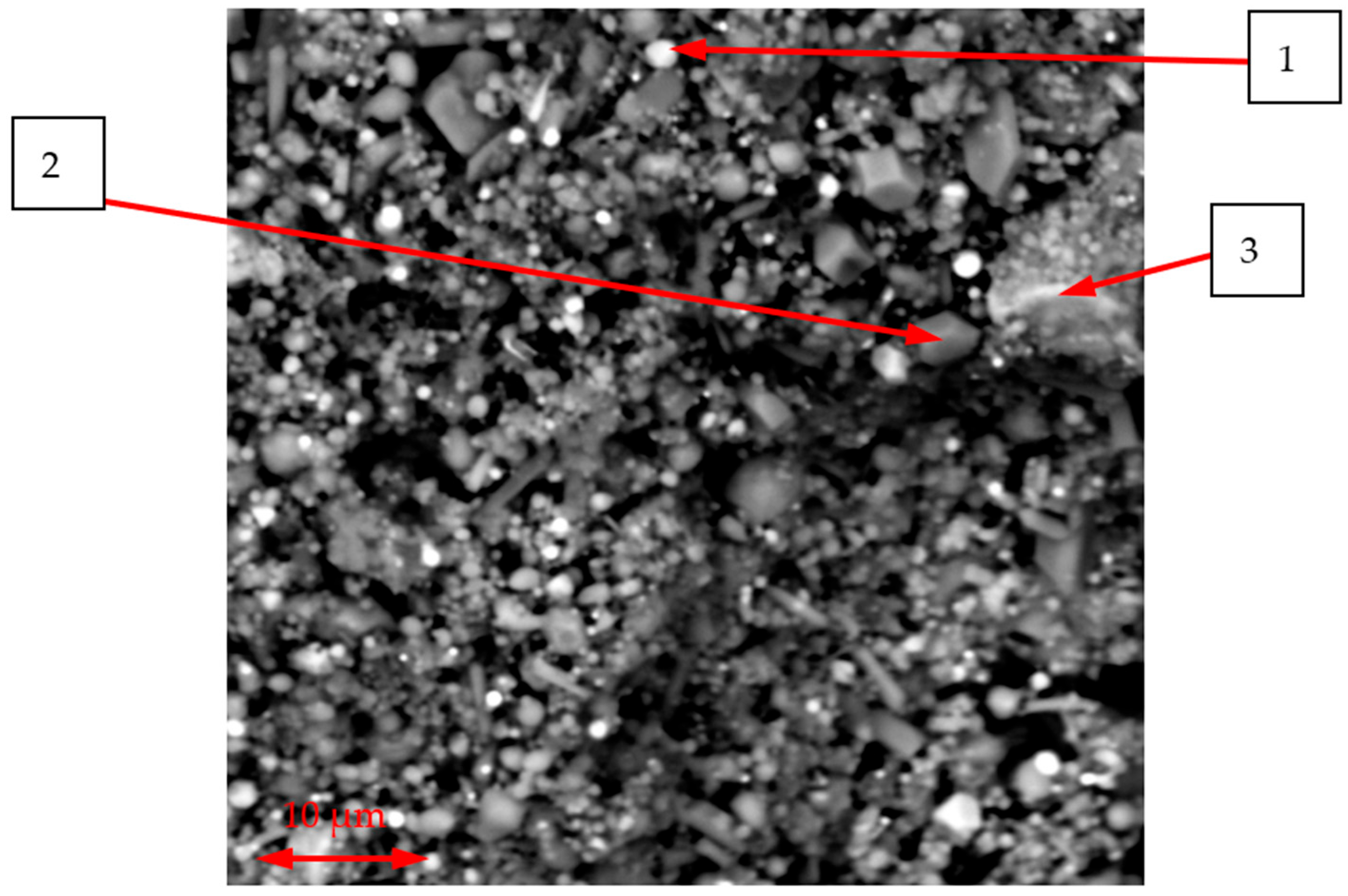
Figure 2 shows an SEM image of the initial CSP with the locations marked where EDS analysis was performed.
As can be seen in
Figure 2, the CSP consists of a mixture of heterogeneous, dispersed particles with both angular and rounded morphologies. To clarify the phase composition, EDS analysis was carried out on individual particles, with a representative average result presented in
Table 5.
The results in
Table 5 indicate that the particles, while differing in morphology, also exhibit some variation in chemical composition. The representative particles, based on their composition, correspond to typical phases for CSP, such as MgCr
2O
4 and Mg
2SiO
4 [
5].
3.2. Smelting Process
The operating frequency of the induction furnace was gradually increased to ensure uniform heating of the charge. This temperature control strategy allowed for the gradual initiation of reduction reactions, avoiding crucible damage and melt splashing caused by sudden overheating. Simultaneously, the temperature was measured using two thermocouples.
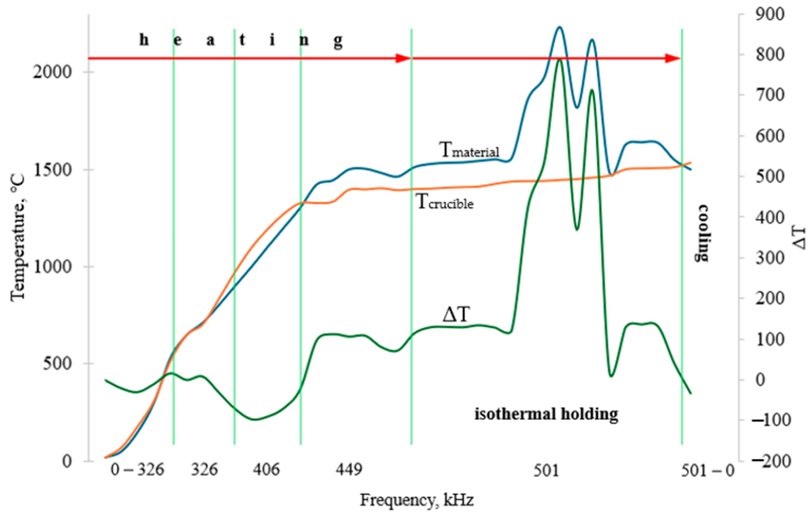
Figure 3 presents the temperature profile of the crucible and the material inside the furnace as a function of frequency for charge B1.
As shown in
Figure 3, up to a frequency of 449 kHz, the temperatures of the crucible and the material remained nearly identical. At 449 kHz, a divergence was observed: the material reached a temperature approximately 100 °C higher, heating to 1450–1500 °C. Since induction heating efficiently transfers heat primarily to the metallic components of the charge, this temperature difference was likely caused by the heating of metallic FeAlSiCa particles [
23,
24].
As the frequency increased further to 501 kHz, complete melting of the material occurred. During the isothermal holding stage, two distinct peaks were observed in the material temperature curve, reaching values of 2161–2231 °C, with a temperature difference of approximately 750 °C compared to the crucible. These peaks are indicative of exothermic reduction reactions taking place as a result of full melting and active interaction of the charge components in the liquid phase.
It should be noted that after an isothermal holding period of 3 min, the crucible containing the melt was removed from the working zone of the induction furnace. This was necessary because longer holding times resulted in the melting of the ceramic crucible. Conversely, insufficient holding led to dispersed metal particles throughout the slag volume, preventing their accumulation at the bottom of the crucible and complicating the separation of metal and slag after solidification.
Such measurements were performed for all charge variants, and temperature variation within the charge remained relatively small, within ±3–7%.
3.3. Alloy and Slag Characterization
Table 6 presents the chemical compositions (determined using the combination of methods described above) of the metal samples obtained from the studied charge variants.
The data reveal trends in the chemical composition depending on the proportion of CSP. A higher CSP content resulted in a slight increase in the Fe content in the metal. A distinct decrease in the Si content—from 7–9% to 1–2%—was observed with decreasing amounts of FeAlSiCa added to the charge. Due to smelting in an atmospheric environment, N absorption by the metal was observed. The presence of V is attributed to its transfer from the FeAlSiCa alloy. The contents of C, S, and P remained consistently low.
The main reduction reactions at 1500 °C can be expressed as:
These highly exothermic reactions drive chromium reduction under experimental conditions, enabling self-sustaining temperatures and efficient transfer of Cr to the metal phase.
In view of the requirements for ferrochrome as defined in ISO 5448-81 [
24], the most comparable standard ferroalloy is low-carbon nitrogen-bearing FeCr. In the A1–A3 series, the Si content is too high (7–9%), while in the B1–B3 series it is somewhat elevated at approximately 2%. According to ISO 5448-81, the maximum allowable Si content is <1.5%. Therefore, only the B1–B3 and C1–C3 series fully meet the requirements of ISO 5448-81.
Table 7 presents the results of chemical composition analysis of slag samples from the various charge variants.
From the data presented in
Table 7, it is evident that a decrease in the proportion of FeAlSiCa leads to an increase in Cr
2O
3 content in the slag. However, the addition of CSP does not result in a significant change in slag composition. The low, near-zero Cr
2O
3 content in the slag from the A1–A3 series suggests that nearly all of the Cr was reduced to the metallic phase. As expected, reducing the amount of FeAlSiCa increases the residual Cr
2O
3 content in the slag. Such low Cr
2O
3 levels indicate that the vast majority of Cr was transferred to the alloy phase, which was a desirable outcome.
The slag basicity for charges A1–A3 was in the range of 0.9–1.0; for B1–B3, it was 0.8–0.9; and for C1–C3, it was 0.9–1.0. These values differ from the basicity levels more commonly associated with low-carbon FeCr production. Nevertheless, the optimal basicity depends on the type of reductant, the characteristics of the raw materials, and the specifics of the smelting process [
11,
14,
25]. Since the slag basicity was nearly identical across all the experiments, further dedicated studies are required to accurately determine the influence of basicity on chromium recovery. At this stage, based on the comparable basicity values, the dominant factor affecting Cr recovery appears to be the amount of reductant introduced.
All the slag samples obtained were observed to solidify into rock-like, mechanically strong masses that showed no sign of pulverization or «dusting» even after >30 days of exposure to air. This lack of slag disintegration is a crucial advantage. It indicates that the slag is mineralogically stable, likely due to the absence or low fraction of phases like β-Ca
2SiO
4 that undergo allotropic conversion and volumetric expansion on cooling. The environmental significance of a stable slag cannot be overstated: a slag that remains as solid lumps minimizes the release of dust and leachable compounds into the environment. FeCr waste handling is complicated by fine dusts and the potential leaching of Cr
6+ if slags/tailings degrade [
8,
26]. In this case, the slag’s resistance to disintegration suggests a lower risk of such issues. Furthermore, the lower Cr
2O
3 content in the slag greatly reduces the concern of Cr
6+ formation in the slag phase, since there is little Cr left to oxidize.
Nevertheless, for a more comprehensive assessment, additional studies and long-term monitoring of the slag during extended storage are required.
3.4. Microstructural Studies
Microstructural analysis was performed on the metal samples. In general, considering the typical composition of the alloys, any potential differences in microstructure were primarily attributed to the use of induction melting and the short holding time.
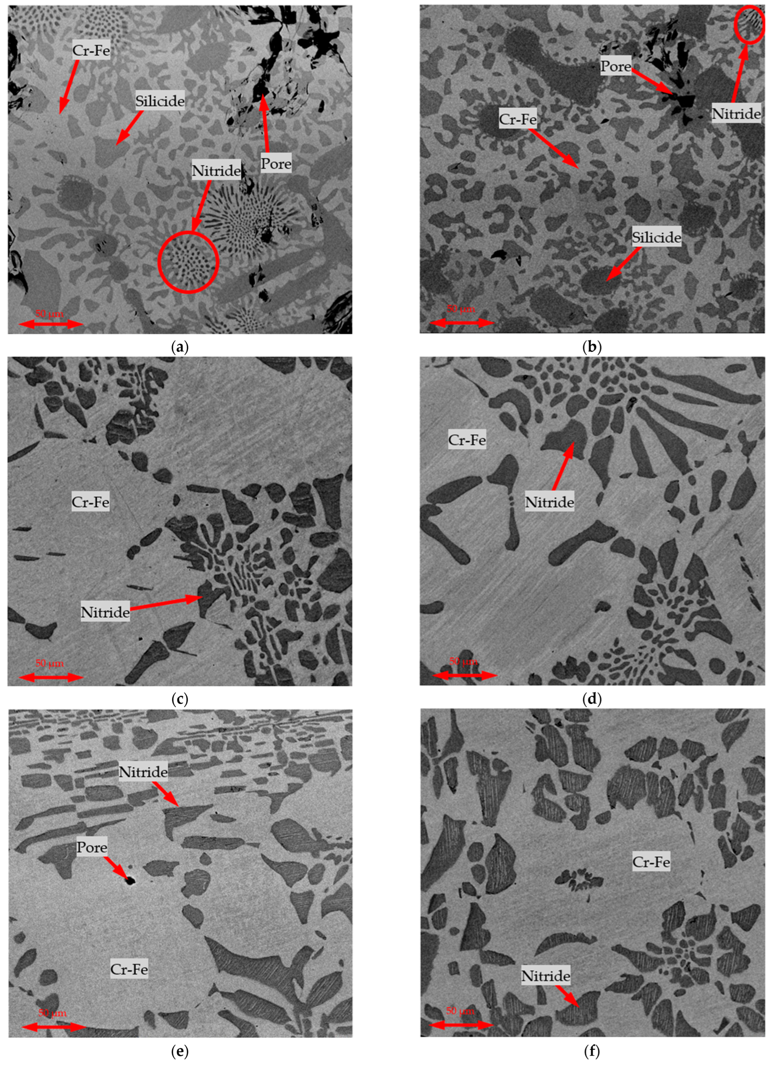
Figure 4 presents representative microstructures of the ferroalloy samples obtained.
SEM images of the microstructures for charges in which 10% of the Cr source was replaced with CSP are omitted, as no significant differences were observed between the samples made with 100% Cr-concentrate and those with 20% CSP substitution.
The main microstructural features were consistent with previously reported results [
10], indicating that induction melting and short holding times did not significantly alter the microstructure formation mechanisms. The sizes of the microstructural components were also nearly identical to those observed during smelting in a chamber furnace at 1650 °C with a 30-min isothermal hold and slow cooling. The high temperatures achieved as a result of exothermic heating—exceeding 2000 °C—likely promoted intensive growth of the microstructural constituents.
In the A1–A3 series, the formation of a silicide phase was observed, which was absent in the B1–B3 and C1–C3 series. In all the series, two phases were consistently present: a Fe-Cr solid solution and a Cr-nitride phase, with V dissolved in the latter, originating from the FeAlSiCa alloy [
14].
Compared to typical SAF-produced FeCr, which often shows coarse dendritic structures and higher Si inclusions, the induction-smelted samples in
Figure 3 display finer, more uniform Fe-Cr solid solutions with well-dispersed CrN phases [
26,
27,
28]. This reflects the rapid heating and controlled exothermic reaction profile. While SAF products may include slag entrapment and variable Si levels, the current process yields alloys with Si < 1.5% and reduced inclusions, improving the final quality [
6].
In summary, the metallographic analysis confirms that short-duration induction smelting can produce a ferrochrome microstructure equivalent to that from more prolonged conventional processes. A high peak temperature can compensate for shorter hold times by accelerating the phase growth. From a practical perspective, this means that the induction metallothermic process is not at a disadvantage in terms of alloy homogeneity or phase development. The product will have the expected phases (matrix + nitrides, plus silicide if Si is high) in the proper scale, ensuring comparable performance to standard FeCr.
A study of the slag microstructure was conducted.
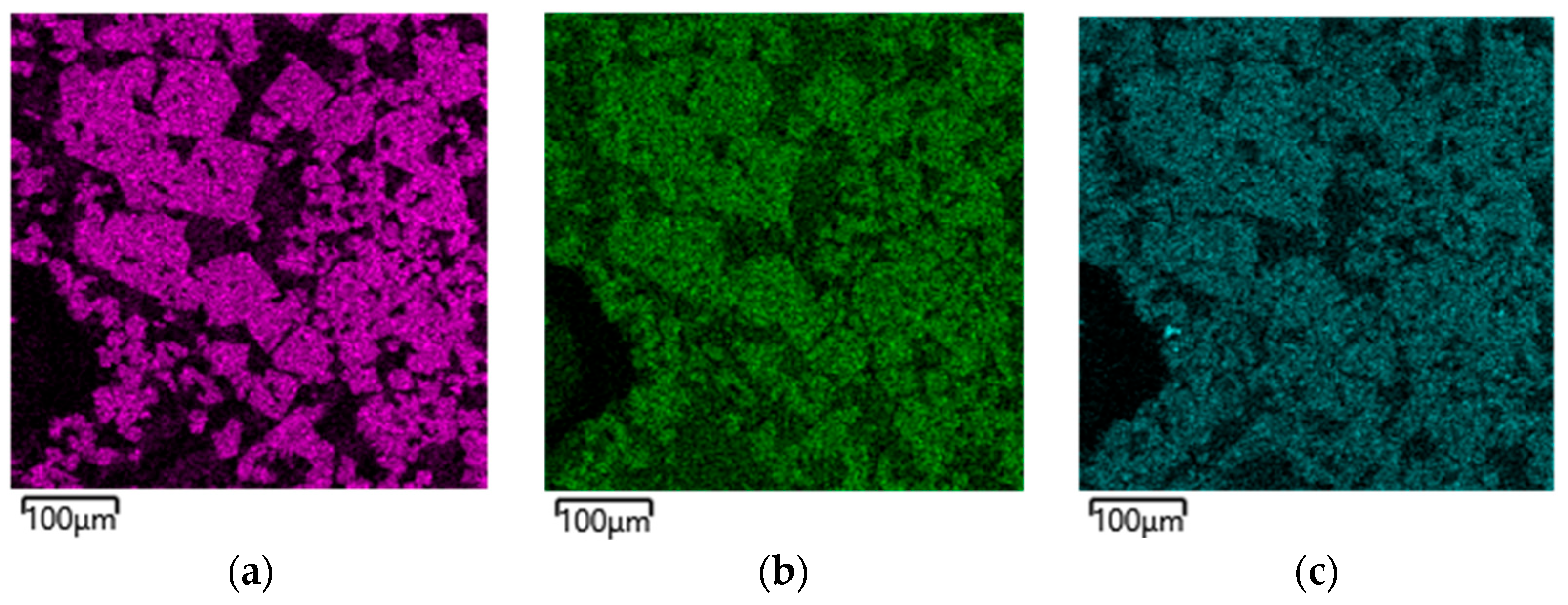
Figure 5 shows the elemental distribution map for slag sample B2, which is representative in composition and whose metal meets the standard requirements.
As seen in
Figure 5, there is a clear segregation of elements into two phases, including Al-O-Mg and Si-O-Ca. This indicates the formation of typical phases such as MgO Al
2O
3 и CaO SiO
2 [
14].
4. Discussion
By analyzing the mass of the obtained metal and slag samples, as well as the Cr and Cr
2O
3 contents in each, the chromium recovery rates were calculated for the various charge compositions studied. The results are presented in
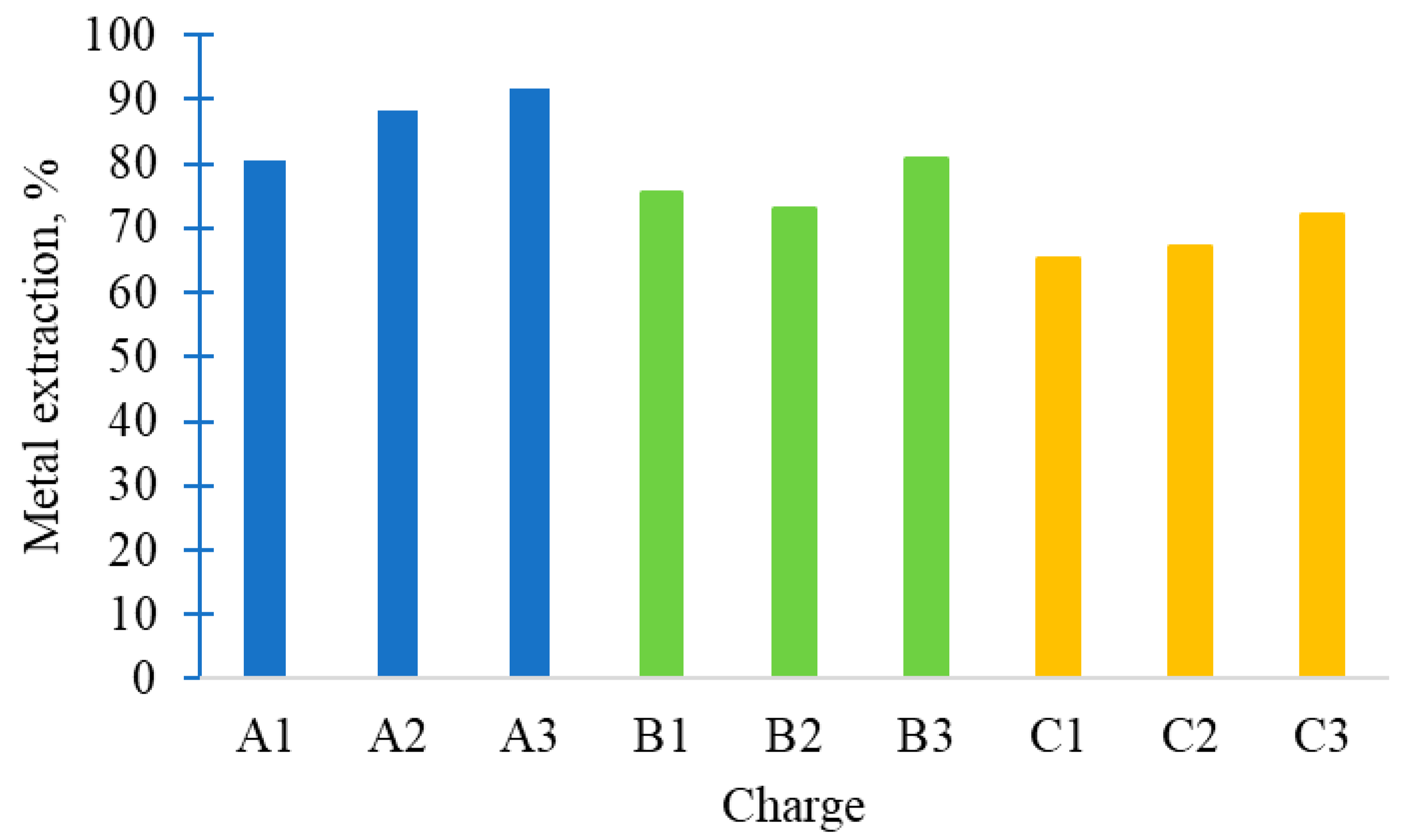
Figure 6.
It can be seen that the Cr recovery decreased sharply with a reduction in the amount of FeAlSiCa added. Slightly improved Cr recovery was observed with the introduction of CSP. This may be because the fine CSP, with its high reactivity, facilitates more efficient reduction of Cr. Overall, the optimal charge B1–B3 achieved a Cr recovery of ~75–80%, fully meeting low-carbon FeCr specifications. This recovery is comparable to the upper range reported for closed submerged-arc furnace (SAF) operations (83–88% Cr recovery when using pre-oxidized pellets) and higher than the 70–75% typical of conventional SAF smelting of unscreened chromite [
8]. Such high yields in a one-step metallothermic process highlight the efficiency of the FeAlSiCa reductant.
Typically, industrial FeCr smelting is conducted at temperatures of 1600–1700 °C. In this study, during the isothermal holding stage, the crucible temperature ranged from 1400 to 1533 °C. The necessary thermal conditions were achieved within the charge itself due to the exothermic heating effect resulting from the oxidation of FeAlSiCa components. The effective utilization of chemical energy from the alloy is advantageous for process efficiency.
Higher reaction temperatures and sufficient hold times favor more complete reduction of chromite [
6,
29,
30]. In this case, the localized thermal spikes from the metallothermic reactions likely helped drive the Cr reduction to completion even though the overall hold temperature was modest.
The combined effect of exothermic reactions raises local temperatures, enhancing reduction kinetics and driving the process without external carbon. The presence of CaO and Al2O3 in slags also improves their basicity and stability, leading to dense, non-pulverizing slags with low Cr2O3 residues.
The main reduction reactions involved Al, Si, and Ca, producing metallic Cr and solid oxides (Al2O3, SiO2, CaO) in the slag, with only minor carbon input (there may have been a trace of carbon in the FeAlSiCa alloy, but no direct coke usage). Thus, the process can be deemed carbon-free smelting in terms of the reductant, as intended. Any CO2 generation was minimal, coming perhaps from the decomposition of residual carbonates in the ore or the insignificant oxidation of atmospheric carbon. This directly translates to lower greenhouse gas emissions per ton of ferrochrome. Even considering the upstream production of the FeAlSiCa alloy, if that alloy is produced using green electricity or sourced from industrial residues, the overall CO2 footprint remains far lower than the classic route. Our study touts this benefit: a reduced carbon footprint and improved process sustainability were achieved while still producing the target alloy.
The stability and safety of the process are improved from an environmental perspective. Smelting with carbon in an open SAF often results in a CO-rich off-gas that must be flared or cleaned, and there is a risk of combustible gas accumulations. In induction furnace trials, no explosive gases were generated—the off-gases were limited to some nitrogen, perhaps a small amount of CO (due to the small carbon content in the composition of the reductants), and metal vapors that quickly oxidized (forming a small amount of dust). The elimination of a CO off-gas stream also eliminates wasted energy; in conventional ferrochrome plants, the chemical energy of CO is often not recovered and is simply burned to CO
2 [
5,
26,
31,
32].
Here, the energy stayed in the system in the form of heat (thanks to the aluminothermic exotherm) rather than leaving as CO gas. Moreover, dust and fumes were relatively low. No significant evolution of smoke was observed once the charge became fully molten. This contrasts sharply with oxygen-blown converters used for low-carbon FeCr production, which typically emit large volumes of CO/CO2 and fumes containing Cr-bearing particles that require scrubbing. The absence of oxygen blowing and high off-gas velocities in the present process inherently results in lower airborne emissions.
Any particulate that did carry over (e.g., oxides of Al/Si) would be far less hazardous than Cr-containing fumes. Importantly, the formation of Cr
6+ was minimized. Cr
6+ can form when Cr
2O
3 in slag or dust is exposed to oxygen at high temperatures. The patent literature on aluminothermic FeCr emphasizes using an inert gas cover to prevent Cr
6+ formation [
33]. In this case, although the smelting was conducted under an air atmosphere, the internal environment of the reaction remained highly reducing due to the active oxidation of Al and Si, which consumed the available oxygen. This likely kept most of the Cr as Cr
3+ in the slag and metal, with negligible Cr
6+ in any fumes. The stable, non-dusting slag further means that any leachable Cr
6+ in slag will be extremely low, especially since the residual Cr
2O
3 was under 1% and mostly bound in spinel form (Cr
3+ solid solution). By comparison, waste streams from conventional processes (like filter dust or wet scrubber sludge) can contain some Cr
6+ that necessitates treatment [
8,
26,
34,
35]. The formation of Cr
6+ was effectively avoided at the source, primarily as a result of the absence of direct oxygen injection and the consistently reducing conditions maintained throughout the process.
5. Conclusions
This study confirmed the technical viability and metallurgical effectiveness of using FeAlSiCa as a reductant for the production of low-carbon ferrochrome from high-grade chromite concentrate (Cr2O3 ~52%) and CSP. The approach proved advantageous in terms of reducing the carbon footprint, utilizing fine industrial by-products, and avoiding Cr6+ formation due to the strongly reducing conditions and the absence of oxygen injection.
Among the three charge configurations (12, 14, and 16 kg FeAlSiCa per 100 kg of Cr-bearing feedstock), the 14 kg variant (B1–B3) demonstrated the best overall performance, achieving Cr recovery up to 80%, Cr2O3 residuals in slag of 9–10%, and a final alloy composition fully compliant with ISO 5448-81 standards for nitrogen-bearing low-carbon FeCr. Despite being carried out in air, the oxidation of Al and Si from FeAlSiCa maintained a reducing environment, suppressing unwanted oxide formation.
The slags produced across all variants were solid, dense, and resistant to degradation during air exposure, with basicity values ranging from 0.8 to 1.0. While these values differ from those traditionally used in low-carbon FeCr processes, they had limited influence on Cr recovery under the current experimental conditions, where the reductant quantity emerged as the dominant factor.
Microstructural analysis revealed typical solidification structures, including Fe-Cr solid solution and CrN phases, consistent with prior studies but formed under substantially shorter holding times and distinct thermal profiles enabled by induction heating. The use of an induction furnace facilitated high-temperature exposure through both external heating and internal exothermic reactions, while avoiding the formation of a CO off-gas stream and associated energy losses.
The results underscore the potential of CSP valorization and FeAlSiCa-based reduction in cleaner, more energy-efficient FeCr production. Future work should focus on scaling the process, evaluating CSP reuse potential, and performing smelting under vacuum or inert atmospheres, as well as in arc furnaces commonly used in industrial ferroalloy production.


 ,
, 

