Article

Experimental Study on the Influence of Magnesium on the Separation of Carbon Dioxide from Gas Mixtures with Nitrogen by Combustion Processes

by
Ioan Barabulica
,
Marius Sebastian Secula
*,
Eugenia Teodora Iacob-Tudose
* and
Ioan Mamaliga
Department of Chemical Engineering, Faculty of Chemical Engineering and Environmental Protection “Cristofor Simionescu”, “Gheorghe Asachi” Technical University of Iasi, 700050 Iasi, Romania
*
Authors to whom correspondence should be addressed.
Processes 2025, 13(7), 2054; https://doi.org/10.3390/pr13072054
Submission received: 23 May 2025 / Revised: 24 June 2025 / Accepted: 26 June 2025 / Published: 28 June 2025

Abstract

The goal of this paper consists in the experimental evaluation of the possibility to separate industrial gases using magnesium combustion in carbon dioxide–nitrogen mixtures of various concentrations. The choice was made primarily due to the chemical inertness of these two gases. The study investigates how the Mg combustion changes the concentration of the initial gas mixture and the possibility to apply this process to separate this gas mixture. On the other hand, due to its greenhouse effect, CO2 separation is a process of high interest in itself. Mg reacts exothermically with CO2, so a potential use for this purpose will also benefit from a significant amount of recovered thermal energy. N2 has a particular importance due to its potential to be purified using Mg combustion, and this application might be an economical alternative to air distillation, which is widely used for N2 production at industrial scale. In practice, the CO2-N2 mixtures are commonly used as flue gases resulting from various combustion systems. Mg combustion residue is analyzed by means of energy-dispersive X-ray spectroscopy. It is found that Mg can substantially reduce the concentration of CO2, even more than the stoichiometric reaction for the formation of MgO would suggest. The percentage decrease in CO2 concentration reaches values over 10 vol.%. A secondary yet notable effect is the heat generated by the Mg and CO2 reaction, which is currently being studied as an energy source alternative.

1. Introduction

Magnesium combustion has become a subject of increasing attention due to its potential applications in gas separation processes, particularly in reaction with gases like N2 and CO2 [1,2,3,4,5,6,7]. Thus, the heat of formation of Mg3N2 obtained through the reaction between Mg and N2 was experimentally determined [8]. The composition of Mg3N2 can be established by analyzing N2 content via ammonia titration and Mg via phosphate precipitation. It was also observed that Mg3N2 is strongly fluorescent in bright orange ultraviolet light showing that its surface contains adsorbed oxygen. The ignition behavior of Mg and its alloys has been the subject of safety-focused studies due to their use in high-temperature applications, particularly in the aeronautical sector; however, a lack of sufficiently eloquent tests was highlighted [2,4,7,9]. Experiments under various gas compositions (e.g., O2, O2-SO2, O2-N2) and pressures (0.166–10 atm) established that while the presence of a MgO layer can inhibit ignition, the partial pressure of oxygen exerts a stronger influence. Some alloying elements were shown to lower Mg’s ignition temperature below its melting point, emphasizing the importance of understanding these effects when designing Mg-based components.
Paul reported several key findings regarding Mg combustion in CO2, N2 and water vapor [10], showing that the reaction enthalpy with N2 and CO2 reaches approximately 25% and 60%, respectively, of that released during combustion in air. This energy release highlights Mg’s promise in both reactive and thermal applications. Combustion behavior was further analyzed by Dupre and Streiff [11], who observed that Mg reacts differently with N2 below and above 500 °C, with a rate-limiting step tied to nitrogen adsorption at the metal–gas interface. At higher temperatures, Mg sublimation and the breakdown of surface oxide layers allow vapor-phase combustion, with kinetics influenced by N2 purity and pressure.
Key rate-limiting factors include N2 adsorption at the metal–gas interface and Mg sublimation. The presence of a protective MgO film delays ignition by requiring Mg vapor to diffuse through it. N2 purity and pressure further influence these interactions. When modeling Mg combustion, distinct stages are identified: heating, melting, molten without combustion, molten with combustion, and full combustion [12].
Additional studies have explored Mg nitridation in gas mixtures, including NH3-N2 systems [13]. Submicron Mg3N2 particles were synthesized via vapor deposition at low pressures (~1 kPa), with optimal reaction temperatures around 800 °C. Cui et al. [14] further reduced this temperature by using activated Mg doped with NiCl2, characterized by DTA and TEM analyses.
With the growing demand for magnesium (Mg), especially in the aerospace and aeronautical industries, there is an increasing need to optimize production processes, particularly electrolytic methods [15,16].
Mg oxidation behavior in mixed atmospheres such as N2-CO2 has also been investigated. Aleksandrova et al. [17] addressed the issue of the protective atmosphere and film at the metal–gas interface through experimental studies using various gas mixtures including N2, CO2, SO2, and SF6. The thermodynamic equilibrium of electrons between the metal to the oxygen adsorbed by the metal–metal oxide layer formed between the metal mass and the gaseous atmosphere stands as the basic relationship for the Mott–Cabrera theory of metal oxidation modeling [18]. The basic idea of this theory is that the transfer of ions through the growing oxide layer is assisted by an existing electric field resulting from the negative charge of the adsorbed oxygen anions and the opposite charge of the metal side. The thickness and nature of the various reaction product layers were also determined. Thus, in the case of the gaseous phase formed by N2 and CO2, it was shown that a thin oxide film forms on the Mg surface, causing a slight decrease in the evaporation process. The oxidation process of Mg in the N2-CO2 gas mixture was stabilized at a concentration of 40–50% CO2, leading to the formation of a relatively thick layer on the metal surface. At a concentration of 50%, confirmed by the decreasing Mg composition in this layer, a layered structure occurs. This consists of a thin layer of MgO on the metal surface followed by a thicker and more porous layer of MgO and black carbon. Finally, a thick layer of black carbon covers the entire structure resulting from combustion.
Shafirovich et al. [19] examined Mg-CO2 reactions under controlled conditions, finding that ignition requires heating to Mg’s melting point due to the passivating oxide film. Upon breakdown of this film, the reaction proceeds in the gas phase, producing a residue with layered MgO and carbon deposits. Thermodynamic analysis indicated that excess CO2 near the particle surface can lead to the formation of MgCO3 or elemental carbon through disproportionation reactions (2CO → CO2 + C), especially below 1000 K.
Given these findings, the selective removal of CO2 from CO2-N2 mixtures using Mg combustion emerges as a viable method for gas separation. This is particularly relevant for the treatment of industrial flue gases. The reaction not only reduces CO2—a greenhouse gas of major environmental concern—but also generates recoverable thermal energy. Meanwhile, N2 enrichment through this method could serve as a low-cost alternative to energy-intensive air distillation processes, currently dominant in industrial nitrogen production. Therefore, the present study investigates the combustion of Mg in CO2-N2 mixtures, focusing on compositional changes in the gas phase and evaluating the feasibility of using this process for industrial gas separation. The practical value derived from the study regarding flue gases could be the nitrogen separation by consuming carbon dioxide in the reaction with Mg. The separated nitrogen could be used in industrial applications (i.e., ammonia production). The investigated gas mixture can also be separated through other methods, such as cryogenic processes (liquefaction plus distillation, which involves very high pressures and low temperatures). The idea of using magnesium for separation also accounts for the large thermal energy output, which we consider a key factor in reducing separation costs compared to other methods.

2. Materials and Methods

2.1. Laboratory Experimental Set-Up

To carry out experimental tests to evaluate the reaction of Mg with a binary gas mixture of CO2 and N2, an experimental laboratory set-up was designed as described in [20]. This consists of two main zones, each having as main component a representative piece of equipment: (i) Zone 1 is the reaction or combustion chamber; (ii) Zone 2 is the container for gas mixture preparation.
The functionality of the experimental set-up was ensured by means of two auxiliary systems. The first one allows the optimal adjustments for the reaction and test preparation chambers. The second auxiliary system ensured the starting and running the tests by means of an electric rectifier, a switch, and connectors. An analytical balance (precision 0.1 mg) was used to determine the mass of the Mg sample. Figure 1 shows the interconnections between the specific zones of the experimental set-up and its auxiliary systems.
Commercial pressurized gas cylinders were used for the preparation of gas mixtures. Flexible tubes equipped with valves for gas flow control ensured the connections between the experimental facility zones.
The design of the most representative equipment within the experimental set-up was based on calculations starting from the premise that during the reaction of Mg (weight of 10 mg) and CO2, less than 10 wt.% of the initially present reactant gas in the reaction chamber would be consumed. The mixing room for preparing the gas mixture was sized so that it could store the gas mixture for five consecutive tests.
The central element of the laboratory set-up (Figure 2) is represented by the reaction chamber. It is provided with a gas supply, connection to the vacuum system (auxiliary system 1), depressurization, reaction zone visualization, and power supply.
The mixing room for the binary gas preparation was built with connections to N2 and CO2 supplies, reaction chamber, vacuum system, and toward the depressurization valve.
The gas mixtures used in the experiments replicate, within certain limits, the gas mixtures resulting either from combustion or from industrial processes. The experiments were reproduced using an approximate mass of Mg (±0.1 mg) and gas mixtures of known concentration.
The preliminary preparations consisted in designing the technological scheme of the laboratory set-up, designing the essential equipment (reaction and mixing chambers), building the experimental set-up, and conducting preliminary tests for choosing the resistance for Mg heating. The mixture preparation tank and the test chamber are equipped with analogue pressure gauges (Ferro, Poland, max. 10 atm, 0.1% accuracy). Temperature measurements in the test chamber were performed using two thermocouples (Pt 100) connected to a data logger (Sper Scientific, Visalia, CA, USA 800024. Thermocouple Thermometer, 4 Channel Data Logger). Temperature recordings were made every 3 s. The time delay constant is low and does not influence the temperature profile.

2.2. Combustion Tests

The gas mixture prepared for the Mg reaction was composed of CO2 and N2 in varying proportions. Compared to results reported in the literature, preliminary tests conducted to study the thermal effect showed that the more reactive gas in the considered binary mixture is CO2. This also allows a simplified analysis of CO2 concentration. Substances that react with CO2 at a very high rate are represented by alkali and alkaline earth bases. From this category, barium hydroxide Ba(OH)2 was selected to analyze the composition of binary CO2-N2 mixtures. With this aim, a 20 g/L Ba(OH)2 solution was prepared.
The quantitative analysis is based on bubbling a gaseous mixture containing CO2 through Ba(OH)2 solution. This method comprises five steps: preparation of Ba(OH)2 solution, gas sampling, weighing the bubbler with a given volume of Ba(OH)2 solution, bubbling the gas sample through the weighed volume of solution, and finally weighing the bubbler after the gas volume has passed through. Thus, a relationship between the concentration of CO2 in the gas phase and the mass variation of the bubbler was determined. For this purpose, gas samples of known volumetric concentration were collected and analyzed using a volumetrically graduated gas container. To determine this reference curve, seven gas samples of different concentrations were used. A volume of 75 mL Ba(OH)2 solution 20 g/L was used. Each determination was performed 3 times and the values represented on the calibration curve correspond to the average of these measurements. Data obtained are shown in Figure 3, and the model is expressed by Equation (1).
y = 0.2 + 38.3967 · x 20.4453 · x 2 + 30.9687 · x 3 .
To prepare the Mg sample, two fragments were cut from a roll of Mg strip with a length of approximately 15 mm and a width of 5 mm. At each end holes were made for fixing the kanthal wire (heating resistance) with a diameter of 0.7 mm, and Mg samples were overlapped and positioned in the middle of the kanthal wire (90 mm in length). The kanthal wire was weighed before and after the introduction of the Mg samples, thus determining the mass of Mg subjected to analysis. Then it was introduced into the reaction chamber and was connected to the electrical power source. Successive pressurization and depressurization procedures were carried out to remove oxygen from the reaction chamber [20]. The pressurization for the experiment is performed with the gas mixture from the mixing container (Element 2 in Figure 2). The working pressure in the experiments was set and kept constant at 0.2 mPa absolute pressure. This pressure value was set to ensure the amount of gas for analysis so that the pressure in the vessel would be sufficient to collect the final sample.
After the reaction chamber was pressurized to 0.2 mPa with the gas mixture, a sample (initial) was collected with a 100 mL syringe through a fitting adapted for the syringe tip. After filling the syringe with gas, the tip was covered with a sample cap to ensure the gas seal inside, and the pressure in the reaction vessel became 0.175 mPa. The experiment begins when the electrical circuit including the kanthal wire is closed. Upon completion of the reaction, when the temperature drops below 50 °C, the final gas sample is collected. The analysis of the collected samples was conducted following a specific sequence of operations: adding solution to the vial, weighing the vial to get the initial mass (m1), bub-bling the gas sample through the solution, weighing the vial for the final mass (m2), emp-tying the vial content, and washing the vial and bubbler with distilled water. The mass variation Δm = m2 − m1 corresponds to a value of the CO2 concentration on the reference curve.
As reported in our prior work [22], the parameters in real-gas state equations closely approximate ideal gas behavior at low pressures. Therefore, ideal gas laws were used to characterize the gas mixtures behavior. Since pressures and temperatures were low, the deviation from ideality was below 2%.

3. Results

3.1. Influence of Gas Composition of Mg Combustion Parameters

Table 1 presents the experimental conditions for eight combustion runs, highlighting the initial and final CO2 concentrations and the corresponding change due to the reaction with Mg.
Table 2 summarizes the elemental composition of the solid combustion residues in various CO2-N2 gas mixtures. For each sample, three determinations (labeled a, b, c) were carried out, and the results are given as weight percentages. The data reveal that Mg and O are the predominant elements, confirming the formation of oxidized Mg compounds such as MgO and MgCO3. Carbon content varies significantly, indicating differences in CO2 reduction pathways, while N traces suggest partial formation of Mg3N2. The average percentage decrease in carbon dioxide concentration obtained in the experimental series can be considered to be around 10%. The average percentage decrease in carbon dioxide concentration obtained in the experimental series can be considered to be around 10%. This is comparable to other separation techniques such as absorption in pressurized water [23] or by reactive absorption in amine solutions [24] where the solute weight percent in amine solution is up to 10% depending on amine type, amine concentration, and operating conditions. Minor traces of chromium and iron are specific to SEM-EDAX analyses and partly also attributed to contamination from the experimental set-up.
The main steps of the Mg combustion if N2-CO2 are reported in detail in our prior work [20]. Figure 4 shows the temperature profile of Mg combustion in presence of N2-CO2 mixtures. The ignition time was considered the beginning of the temperature peak formation, whereas the combustion time is the length of this temperature peak.
The temperature evolution represents the imprint of the heating, combustion, and cooling processes during the series of tests performed. The following zones can be distinguished: (i) a heating zone—starts from the moment of electrical coupling of the kanthal wire, up to the temperature at the base of the maximum thermal jump; (ii) combustion zone—represents the maximum thermal jump and any subsequent increases; (iii) Cooling Zone 1—starts from the first lower temperature after the maximum thermal jump and ends at the moment of recording a temperature increase due to the thermal effect of the kanthal wire or its disconnection from the electrical circuit; (iv) Cooling Zone 2—represents the final cooling, starts from the moment of disconnecting the resistance and until the end of the recording.
There is an interconnection between these zones of temperature profile and the characteristic combustion parameters, namely in that the heating zone may coincide with the ignition time and the combustion zone with the burning time, with the specification that the combustion parameters were extracted from the video recording and the temperature values were extracted from the display of the digital device used to transform the signal received from thermocouples T1 and T2 into temperature values. The observable gap is due to the delay in displaying the real temperature of the digital device. Another observation regarding the connection between the thermal and combustion parameters is that at short ignition times, the maximum recorded temperature has lower values in relation to the climax of the thermal jump, although, at higher N2 concentrations, multiple successive temperature jumps caused by the combustion of Mg were observed, yet of lower values (less than 20 °C).
In common industrial practice, the CO2-N2 gas mixture is represented by the combustion gases resulting from the energetic use of fossil fuels. For this reason, the experimental investigation focused on a concentration range close to 80% N2, a value similar to that found in flue gases. Considering the substantial thermal effect of the reaction of Mg with CO2 from a binary gas mixture CO2-N2, the flue gases could be further used for energy purposes by extracting carbon from CO2 with the help of Mg, as can be seen from the results of the experimental series presented.
As highlighted in the experimental stages, the parameters that characterize combustion are the ignition and combustion temperatures.
Figure 4 shows a distinct temperature peak immediately after Mg combustion reaction is initiated. The highest value of temperature (T1) is reached in low-N2-content mixtures. As shown in Figure 4a, the ignition and combustion time as well as temperature vary in case of replicated tests. In case of the experimental set of tests conducted in 32.7% N2, the ignition time is 157 ± 12 s, peak temperature near the Mg sample (T1) is 264.5 ± 12.02 °C, and peak temperature near reactor’s wall (T2) is 104.2 ± 5.31 °C.
By investigating the evolution of temperature variation, certain sharp jumps can be noticed, which are in fact the graphical representation of combustion phase. The combustion process takes place with substantial heat release in a relatively short time, so the thermal peak represents the measured expression of the ignition of Mg in the binary CO2-N2 mixture. The ignition time is approximately the time at which this thermal peak is beginning to occur on the graph of temperature evolution. The ignition time specified in the presentation of the experimental data was extracted from the video recordings of each experimental run. After each experimental series, the combustion and ignition time were determined as combustion parameters. The ignition time is the moment of the beginning of the thermal peak and is correlated with the observation of the ignition on the video recording. The combustion time represents the time during which the luminous effect of the burning is observed on the video recording or the time from which a temperature decrease is recorded on the time variation graph, even with the electric heating source switched on.
These characteristic parameters for combustion processes show some dependences on the gas compositions used in the tests. According to the literature, the combustion reaction takes place mainly between Mg and CO2. Thus, from a theoretical point of view, N2 acts as a dilution agent for the CO2 fuel gas and the combustion process proceeds similarly to the data reported in the literature [18]. However, empirically, the experimental results for combustion phenomena can be analyzed by plotting the ignition and combustion time values in relation to the concentration of the reaction atmosphere.
In Figure 5a,b, one can observe that at low N2 concentrations, Mg ignites more slowly (high ignition time), yet once ignited, it burns very quickly (relatively short burning time-maximum 3; 4 s) and releases a large amount of heat (the thermal jump is among the highest values). At high N2 concentrations, the ignition time tends to reach 1 min, while the combustion time often exceeds 5 s. At intermediate CO2-N2 concentrations, the combustion processes take place at a more consistent pace, the ignition time values are among the shortest, usually under a minute (60 s), and the burning time values are mostly under 5 s.
The combustion process also depends on the amount of fuel introduced and the energy consumed to initiate the process. Thus, for the series of experiments with a larger amount of Mg (approximately 40 mg), a higher voltage (9 V) was used to activate the reaction, which is reflected in the shorter ignition time recorded for these tests. For the other tests, 7 V was used to activate the reaction. The influence of the larger amount of Mg was also observed in the longer burning times than in the equivalent tests with smaller amounts of Mg. In other words, the amount of energy supplied to activate combustion influences the ignition time, and the amount of combustible material influences the burning time.
According to the literature, the reaction mechanism between CO2 and Mg involves two stages: the initiation of the reaction of Mg vapor with CO2 in the gas phase (a homogeneous reaction) followed by the reaction at the metal–gas interface (a heterogeneous reaction). Thus, the experimental observations can be explained in the first phase by the formation of Mg vapor during the ignition time, followed by the initiation and development of combustion. Unlike the conditions reported in the literature, the experiments conducted in this study were initiated under cold start conditions, meaning that both the reaction atmosphere and the Mg sample were at room temperature. The thermal energy supply for the initiation of the reaction was applied to the Mg sample, which heated up faster than the surrounding gas, so the initiation of the reaction in the gas phase took place near the heating resistance and the Mg sample.
The observed relationship between the variations of in the ignition and combustion times with the concentration of the reaction medium can be attributed to the amount of Mg evaporated by the time of ignition occurs. Specifically, longer ignition times allow for greater Mg evaporation, and since the gas phase ignition and reaction are rapid and highly exothermic, the amount of Mg present is quickly consumed, resulting in a shorter combustion time. If a small amount of Mg has evaporated by the time of ignition and the amount of CO2 available is not too high (in the case of a mixture with a high N2 concentration), then the rate-determining process is the heterogeneous reaction at the metal–gas interface. This aspect is highlighted by the longer burning time, the lower maximum thermal jump, and occasional interruptions in the reaction which are likely caused by non-uniform evaporation occurring at a slower rate than the reaction of Mg with CO2.

3.2. Mechanism of Mg Combustion Process in CO2-N2

The basis for interpreting the analyses carried out in the gas phase is described by the following chemical reaction:
2Mg + CO2 → 2MgO + C,
Based on reaction stoichiometry, it can be observed that two moles of Mg (48 g) consume one mole of CO2, equivalent to 22.42 L at a pressure of 0.1012 MPa and a temperature of 0 °C (standard conditions). The working pressure was 0.2 MPa and the initial temperature was approximately 20 °C. Thus, the molar volume under these conditions becomes
V m o p = n · R · T o p P o p ,
where V m o p is the molar volume under working conditions; n is the number of moles, in this case equal to one; R is the universal gas constant, 8.314 J/(mol K); Top is the working temperature, 20 °C; and Pop is the working pressure, 0.175 MPa.
Therefore, Vm = 13.927 L of CO2 are needed under working temperature and pressure conditions to react with 48 g of Mg. The average amount of Mg used in the experiments to evaluate the influence of Mg combustion on gas concentration was approximately 44.5 mg, which requires about 12.9 cm3 of CO2, equivalent to 3.7% of the reaction chamber volume.
The larger difference between the theoretical required value and the measured value—where most tests indicated a variation in CO2 concentration greater than 3.7%—can be explained by the occurrence of at least two parallel reactions, which can alter the amount of CO2 consumed by Mg during combustion, as described previously:
Mg + CO2 → MgO + CO,
MgO + CO2 → MgCO3,
Mg + CO → MgO + C,
or as a general reaction encompassing all the above-mentioned reactions:
3Mg + 5CO2 → 3MgCO3 + CO + C,
In this reaction, 5/3 moles of CO2 are required per mole of Mg. Under working conditions, this corresponds to 43 cm3 or 12.3% of the reaction chamber volume, a value close to the experimental determinations of CO2 concentration variations. Therefore, concentration variations of up to 12.3% can be explained by the specified reactions, which occur in various proportions.
As reported in the literature, the combustion of magnesium in 100% CO2, initiated in the gas phase, and continued at the metal–gas interface, leads to the total consumption of Mg, with no generation of MgCO3. The heat flux provided by the electrical resistance and the reaction energy result in the evaporation of Mg favoring the total consumption of the Mg sample. The presence of a significant oxygen content is due to the formation of MgCO3. This phenomenon is favored by an excess of carbon dioxide in the gas phase: (i) as a direct reaction to form magnesium carbonate, described in [25]; (ii) from a post-combustion reaction, upon cooling the magnesium oxide, its surface can carbonate through interaction with CO2.

3.3. Characterization of the Solid Residue

Gol’dshleger [26] and Merrill [27] offer a basis for comparison with the results reported herein, confirming that the combustion mechanisms of magnesium in CO2, particularly the formation of MgO, are consistent across various particle sizes, with the diffusion rate of CO2 into the magnesium surface being the key determinant of combustion dynamics. An initial analysis of the solid material resulting from Mg combustion in the experimental series aimed at evaluating the influence of Mg combustion in a CO2-N2 atmosphere on gas concentration was carried out using SEM-EDX spectroscopy on eight samples, with results presented in the previous section. Table 3 shows Mg distribution in combustion residue calculated from SEM EDX analysis.
The analysis of the solid residue using EDX aimed to propose a reaction mechanism. A special focus was applied to the composition of the reaction products rather than their structure. These measurements were deemed sufficient since the experiments were triplicated, and especially due to the fact that the reaction between Mg and gases occurs in the vapor/gas phase, thus excluding the presence of unreacted Mg.
In the first phase, it is assumed that the N2 percentage is due to Mg3N2, so using the detected N2 percentage, the corresponding amount of Mg3N2 can be calculated. From this, the mass of Mg it contains can be determined, which is then subtracted from the Mg percentage detected by the SEM analysis (Figure 6). The following table contains the calculated data and analysis for each sample, with the specification that the molecular mass of Mg3N2 is 100 g/mol, with 72% Mg and 28% N2 composition.
The amount of Mg3N2 was calculated by dividing the nitrogen percentage by 0.28 (the nitrogen percentage in Mg3N2), and the amount of Mg in Mg3N2 was obtained by multiplying the resulting amount by 0.72.
The remaining amount of Mg represents the Mg that can exist in three forms: MgO, MgCO3, and unreacted Mg. To determine the distribution of Mg and O, the following notations were used:
% O % Mg = R ,   and   the   mass   ratio   MgO MgCO 3 = a 1
In the mass ratio between MgO and MgCO3, one has the following amounts of oxygen and Mg:
O: 16 + 3 · 16a = 16(1 + 3a)
Mg: 24 + 24a = 24(1 + a)
R = 2 1 + 3 a 3 ( 1 + a )
From Equation (10) as a function of parameter a, one can also derive the relationship between a and the ratio R:
a = 6 3 R 3 R 2
The limiting cases (12) are as follows:
presence of only MgO, where R = 16/24 = 0.6667,
presence of only MgCO3, where R = 3 · 16/24 = 2,
Therefore, the parameter a is valid only for R values between 0.6667 and 2. Values less than 0.6667 suggest the presence of unreacted Mg, as they indicate an oxygen amount lower than the stoichiometrically required quantity for MgO.
In such cases, the equivalent amount of MgO corresponding to the determined oxygen percentage is calculated from which the Mg amount is derived. This Mg amount is then subtracted from the remaining Mg after removing the amount attributed to Mg3N2 from the analytically determined Mg percentage.
The calculated data are summarized in the following Table 4. From the mass percentages shown in Table 4, one can observe that the oxygen percentage in some analyses is significantly higher than the stoichiometric percentage in MgO, but lower than the oxygen percentage in MgCO3. This leads to the conclusion that a certain proportion of MgCO3 was present in the sample. To determine the percentage of MgCO3 present in the samples and detected via SEM analysis, a discussion on the distribution of the mass percentages is needed.

4. Conclusions

The first conclusion derived from this study is that magnesium can be effectively used in the separation of industrial gas mixtures. By using a gaseous reaction medium composed of carbon dioxide and nitrogen in varying proportions, it was demonstrated that magnesium can selectively react with chemically active components, suggesting its potential application for separating other reactive gases from mixture. Among the two gases studied as the reaction medium, Mg reacts exhibits a clear preference for carbon dioxide, and the reaction can be considered a combustion process—on the one hand due to the sudden thermal increase characteristic to a combustion, and on the other hand due to the appearance of a flame. These indicators allow us to identify the occurrence of an ignition process.
Magnesium can substantially reduce the concentration of carbon dioxide, even more than the stoichiometric reaction for the of MgO formation alone would predict.
It was found that Mg presents higher ignition time values at low N2 concentrations, although the combustion process is fast (about 3–4 s) and a significant energy flux is generated. Conversely, in presence of high N2 concentration, the ignition time increases up to 1 min, whereas the combustion process is longer than 5 s. The analysis of the gas phase during the combustion process confirms the reactions between Mg and the gas mixture. Thus, the deviations from the calculated stoichiometric values indicate that the reaction of magnesium with CO2 can also yield magnesium carbonate as a reaction product, while the presence of N2 leads to the formation of magnesium nitride.
The elemental analysis indicates that in some samples, the oxygen content is significantly higher than the stoichiometric value expected for MgO, but lower than in MgCO3. This leads to the conclusion that a certain amount of MgCO3 was present in the sample. To determine the percentage of MgCO3 of samples and detected via SEM-EDX analysis, further interpretation of the distribution of elemental distribution percentage is needed. In the first phase, it is assumed that the nitrogen percentage is influenced by Mg3N2, allowing the amount of nitride formed to be estimated based on the measured nitrogen content.
A secondary yet important outcome is the considerable thermal effect of the magnesium–carbon dioxide reaction, which is of particular interest as an alternative energy source alternative in space applications.
The implications of these findings can be quite diverse depending on the specific gas compositions encountered in different industrial applications. The most commonly encountered CO2-N2 gas mixture is flue gas, and the experimental results in this study show that Mg can be used to remove carbon dioxide from flue gases, thereby enabling additional energy recovery from the exothermic reaction. Additionally, the process offers the possibility of obtaining a high purity nitrogen free of oxygen contamination, without the energy costs associated with air distillation, with a beneficial environmental impact.

Author Contributions

I.B.: Conceptualization, methodology, formal analysis, investigation, writing—original draft preparation; M.S.S.: conceptualization, methodology, investigation, formal analysis, data curation, validation, writing, review and editing, funding acquisition; E.T.I.-T.: methodology, investigation, validation, review; I.M.: conceptualization, methodology, validation, writing, review and editing, resources, supervision, funding acquisition. All authors have read and agreed to the published version of the manuscript.

Funding

This research received no external funding.

Data Availability Statement

The original contributions presented in this study are included in the article. Further inquiries can be directed to the corresponding authors.

Conflicts of Interest

The authors declare no conflicts of interest.

References

  1. Bai, J.; Yang, Y.; Wen, C.; Chen, J.; Zhou, G.; Jiang, B.; Peng, X.; Pan, F. Applications of magnesium alloys for aerospace: A review. J. Magnes. Alloy 2023, 11, 3609–3619. [Google Scholar] [CrossRef]
  2. Nam, K.-H.; Lee, J.-S.; Park, H.-J. Understanding Combustion Mechanism of Magnesium for Better Safety Measures: An Experimental Study. Safety 2022, 8, 11. [Google Scholar] [CrossRef]
  3. Farooq, M.Z.; Wu, Y.; Lu, L.; Zheng, M. Combustion phases of magnesium alloys based on predicted heating rate using machine learning. Measurement 2025, 242 Pt E, 116192. [Google Scholar] [CrossRef]
  4. Nam, K.-H.; Park, J.K.; Lee, J.-S. Thermal phenomena and size effects of Mg powder in combustion process. PLoS ONE 2024, 19, e0310185. [Google Scholar] [CrossRef] [PubMed]
  5. Zhu, C.; Wang, H.; Min, L. Ignition Temperature of Magnesium Powder and Pyrotechnic Composition. J. Energetic Mater. 2013, 32, 219–226. [Google Scholar] [CrossRef]
  6. Yuan, C.; Huang, D.; Li, C.; Li, G. Ignition behavior of magnesium powder layers on a plate heated at constant temperature. J. Hazar. Mater. 2013, 246–247, 283–290. [Google Scholar]
  7. Zuo, D.; Ding, H.; Zhi, M.; Xu, Y.; Zhang, Z.; Zhang, M. Research Progress on the Oxidation Behavior of Ignition-Proof Magnesium Alloy and Its Effect on Flame Retardancy with Multi-Element Rare Earth Additions: A Review. Materials 2024, 17, 3183. [Google Scholar] [CrossRef]
  8. Horste, F.E.; Mordike, B.L. Magnesium Technology Metallurgy, Design Data, Applications, 1st ed.; Springer: Berlin/Heidelberg, Germany, 2006; pp. 469–632. [Google Scholar]
  9. Wu, L.; Han, F.; Liu, G. Comprehensive Utilization of Magnesium Slag by Pidgeon Process; Springer Briefs in Materials, Open Access Springer: Singapore, 2021; pp. 5–18. [Google Scholar]
  10. Paul, B. A Study of the Flammability of Magnesium; Federal Aviation Agency: Washington, DC, USA, 1964.
  11. Dupre, B.R.; Streiff, R. The Kinetics of Magnesium Nitriding by Pure Nitrogen. Oxid. Met. 1970, 2, 155–160. [Google Scholar] [CrossRef]
  12. Gurevich, M.A.; Lydkin, V.M.; Stepanov, A.M. Ignition and Combustion of a Gas Suspention of Magnesium Particles. Fiz. Goreniya Vzryva 1970, 6, 335–342. [Google Scholar]
  13. Tsuyoshi, M.; Itatani, K.F.; Howell, S.; Kishioka, A.; Kinoshita, M. Preparation of Magnesium Nitride Powder by Low-Pressure Chemical Vapor Deposition. JACerS 1993, 76, 2909–2911. [Google Scholar]
  14. Cui, S.; Liao, S.; Zhang, Y.; Xu, Y.; Miao, Y.; Lu, M.; Fan, Y.; Guo, W. Synthesis of nanometric-size magnesium nitride by nitriding of pre-activates magnesium powder. J. Mater. Sci. 1999, 34, 5601–5604. [Google Scholar] [CrossRef]
  15. Han, D.; Zhang, J.; Huang, J.; Lian, Y.; He, G. A review on ignition mechanisms and characteristics of magnesium alloys. J. Magnes. Alloy 2020, 8, 329–344. [Google Scholar] [CrossRef]
  16. Feng, Y.C.; Xia, Z.X.; Huang, L.Y.; Ma, L.K.; Yang, D.L. Experimental Investigation on the Ignition and Combustion Characteristics of a Single Magnesium Particle in Air. Combust. Explos. Shock Waves 2019, 55, 210–219. [Google Scholar] [CrossRef]
  17. Aleksandrova, Y.P.; Roshchina, I.N. Interaction of Magnesium with Gases. Metalloved. Termicheskaya Obrab. Met. 1977, 3, 52–55. [Google Scholar] [CrossRef]
  18. Perez Ramirez, L.; Bournel, F.; Gallet, J.J.; Dudy, L.; Rochet, F. Testing the Cabrera–Mott Oxidation Model for Aluminum under Realistic Conditions with Near-Ambient Pressure Photoemission. J. Phys. Chem. C. 2022, 126, 2517–2530. [Google Scholar] [CrossRef]
  19. Shafirovich, E.Y.; Gol’dshleger, U.I. Ignition and Burning of Magnesium Particles in Oxides of Carbon. Fiz. Goreniya Vzryva 1990, 26, 3–10. [Google Scholar] [CrossRef]
  20. Barabulica, I.; Secula, M.S.; Asoltanei, M.D.; Iacob-Tudose, E.T.; Lisa, G.; Mamaliga, I. Experimental Study on the Reaction of Magnesium in Carbon Dioxide and Nitrogen Atmosphere. ChemEngineering 2024, 8, 41. [Google Scholar] [CrossRef]
  21. Barabulica, I. Potential Applications of Magnesium in Industrial Gas Separation. Ph.D. Thesis, Chemical Engineering, Gheorghe Asachi Technical University of Iasi, Iasi, Romania, 2025. [Google Scholar]
  22. Negoescu, C.C.; Mamaliga, I. Sorption Kinetics and Thermodynamic Equilibrium of Some Solvents in Polymer Films Using the Pressure Decay Method at Low Pressures. Mater. Plast. 2013, 50, 303–306. [Google Scholar]
  23. Cozma, P.; Wukovits, W.; Mamaliga, I.; Friedl, A.; Gavrilescu, M. Modeling and simulation of high- pressure water scrubbing technology applied for biogas upgrading. Clean Technol. Environ. Policy 2014, 17, 373–391. [Google Scholar] [CrossRef]
  24. Zhang, G.; Liu, J.; Qian, J.; Zhang, X.; Liu, Z. Review of research progress and stability studies of amine-based biphasic absorbents for CO2 capture. J. Ind. Eng. Chem. 2024, 134, 28–50. [Google Scholar] [CrossRef]
  25. Peng, X.D.; Edwards, D.S.; Barteau, M.A. Formation of magnesium nitride layers on the Mg(0001) surface by ion implantation. Surf. Sci. 1987, 185, 227–248. [Google Scholar]
  26. Gol’dshleger, U.I.; Shafirovich, E.Y. Combustion Regimes of Magnesium in Carbon Oxides. 1. Combustion in CO2. Combust. Explos. Shock Waves 1999, 35, 37–644. [Google Scholar] [CrossRef]
  27. Merrill, K. A Simplified Two-Reaction Zone Model of Magnesium Combustion in Carbon Dioxide. Proc. Combust. Inst. 2002, 29, 2931–2938. [Google Scholar]
Figure 1. Experimental set-up flow chart [21].
Processes 13 02054 g001
Figure 2. Technological scheme of the experimental set-up (1—reaction chamber; 2—mixing tank; 3—digital device for monitoring and measuring temperatures in the reaction chamber; 4—vacuum pump; 5—electric current conversion unit; 6—N2 source; 7—CO2 source) [21].
Processes 13 02054 g002
Figure 3. CO2 calibration curve.
Processes 13 02054 g003
Figure 4. Temperature profiles (T1—in the vicinity of the sample, T2—near the wall of the reaction chamber) of Mg combustion in (a) 32.7% N2, and (b) 74.7% N2, respectively.
Processes 13 02054 g004
Figure 5. Influence of N2 on ignition (a) and burning (b) time, respectively [21]: ●—tests conducted with gas prepared directly in the reaction chamber; Processes 13 02054 i004 and Processes 13 02054 i001—tests conducted at 0.3 MPa with gas mixture prepared in the mixing chamber increasing and, decreasing N2 fraction, respectively; Processes 13 02054 i002—tests conducted at 0.2 MPa; Processes 13 02054 i003—combustion tests using high weight Mg samples (40 mg vs. 10 mg).
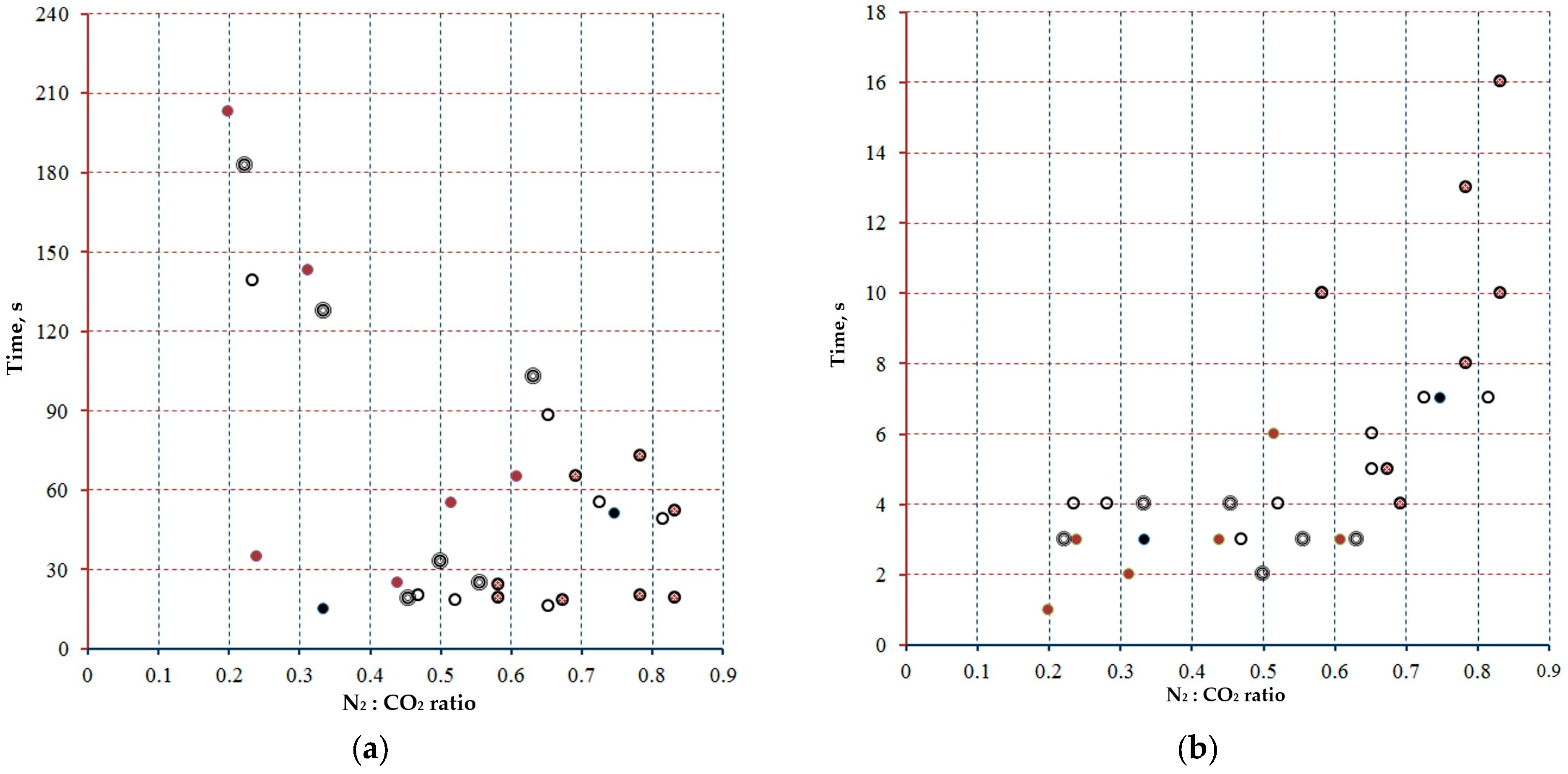
Processes 13 02054 g005
Figure 6. SEM images of Mg residue sample: (a) 100 µm; (b) 20 µm.
Processes 13 02054 g006
Table 1. Experimental design [21].
RunMg Weight, mgInitial Absorbed CO2, vol.%Final Absorbed CO2, vol.%Concentration Change, vol.%
143.272.5259.8612.66
245.854.8135.9518.86
344.252.0241.4310.57
444.614.121.5812.54
541.237.935.961.94
643.319.683.9915.69
744.539.37.0132.29
844.441.4316.4724.98
Table 2. Elemental percentage concentration of Mg combustion residue by SEM-EDX [21].
SampleAnalysesC, wt.%N, wt.%O, wt.%Mg, wt.%Cr, wt.%Fe, wt.%
1a7.861.2935.9754.750.120
b16.581.232.5849.470.170
c30.931.5728.6938.520.290
2a12.441.3333.5452.6900
b28.151.8229.1840.480.370
c22.651.4533.3242.520.060
3a28.662.3127.3241.440.20.06
b26.91.0825.4245.740.680.19
c15.221.7234.7548.20.110
4a19.781.225.453.360.260
b37.681.9321.4338.470.430.06
c16.561.9130.2151.060.260
5a26.561.8933.8237.550.180
b31.781.8634.2431.950.170
c23.111.3231.4643.880.230
6a25.512.4330.9440.820.230.07
b25.771.6231.0441.410.150
c16.021.6833.5248.580.20
7a313.1330.0535.230.450.14
b19.21.5634.3244.790.130
c24.241.529.3944.480.40
8a9.81.8131.1557.050.190
b10.571.8516.0671.080.440
c12.411.0216.7169.650.210
Table 3. Mg distribution with N2 percentage [21].
Sample%N2%MgMg3N2Mg in Mg3N2Remaining Mg
1a1.2954.754.613.3251.43
b1.249.474.293.0946.38
c1.5738.525.614.0434.48
2a1.3352.694.753.4249.27
b1.8240.486.504.6835.80
c1.4542.525.183.7338.79
3a2.3141.448.255.9435.50
b1.0845.743.862.7842.96
c1.7248.26.144.4243.78
4a1.253.364.293.0950.27
b1.9338.476.894.9633.51
c1.9151.066.824.9146.15
5a1.8937.556.754.8632.69
b1.8631.956.644.7827.17
c1.3243.884.713.3940.49
6a2.4340.828.686.2534.57
b1.6241.415.794.1737.24
c1.6848.586.004.3244.26
7a3.1335.2311.188.0527.18
b1.5644.795.574.0140.78
c1.544.485.363.8640.62
8a1.8157.056.464.6552.40
b1.8571.086.614.7666.32
c1.0269.653.642.6267.03
Table 4. Distribution of Mg left after extracting the amount assimilated to the N2 percentage in relation to the percentage of oxygen detected [21].
Sample%OO/Mg Ratioa% MgCO3MgOMg in MgOUnreacted MgUnreacted
%Mg
1a35.970.6993639.792.51----
b32.580.7002436.322.75----
c28.690.837.0614.16----
2a33.540.6893.751.07----
b29.180.827.9812.53----
c33.320.865.9316.85----
3a27.320.7711.968.36----
b25.420.59--63.5538.134.837.07
c34.750.799.4910.54----
4a25.40.51--63.538.112.1716.09
b21.430.64--53.57532.1451.362.48
c30.210.65--75.52545.3150.831.09
5a33.821.032.6238.11----
b34.241.261.2580.26----
c31.460.7811.089.03----
6a30.940.894.8420.66----
b31.040.837.0014.29----
c33.520.7613.707.30----
7a30.051.112.0449.06----
b34.320.846.6215.10----
c29.390.7222.474.45----
8a31.150.59--77.87546.7255.676.79
b16.060.24--40.1524.0942.2351.26
c16.710.25--41.77525.06541.9650.11
Disclaimer/Publisher’s Note: The statements, opinions and data contained in all publications are solely those of the individual author(s) and contributor(s) and not of MDPI and/or the editor(s). MDPI and/or the editor(s) disclaim responsibility for any injury to people or property resulting from any ideas, methods, instructions or products referred to in the content.

