Abstract
Gas extraction is an important means to reduce coalbed gas and ensure safe coal production. Injecting N2/CO2 into a coalbed can enhance coal seam gas extraction, but problems with N2/CO2 sources underground have prevented the wide application of this technology in coal mines. The air contains a large amount of N2, but only a few studies have investigated the injection of air into coalbeds to facilitate gas extraction. In this study, a thermal–hydraulic–solid coupling model for air-enhanced coalbed gas extraction (Air-ECGE) was established. Additionally, the impact of air injection on coalbed methane extraction was simulated, and field experiments were conducted on air injection to enhance gas extraction. The results showed that injecting high-pressure air into a coalbed can effectively facilitate gas desorption and gas migration within the coalbed, greatly improving the efficiency of gas extraction in the coalbed. In addition, owing to the large pressure gradient that can lead to fast coalbed gas seepage, the gas production rate of the extraction borehole is directly proportional to the gas injection pressure. Further, the spacing of the boreholes limits the influence range of the gas injection: the larger the spacing, the larger the influence range, and the higher the gas extraction rate of the extraction borehole. After injecting air into the coalbed of the Liuzhuang coal mine, the extraction flow rate and concentration of gas from the extraction boreholes both increased significantly. A certain delay effect was also observed in the gas injection effect, and the gas extraction flow rate only decreased after a period of time after the gas injection had stopped.
1. Introduction
Coal is the primary source of energy consumption in China, accounting for 64% of the total energy consumed in the country in 2021 [1,2,3]. However, coal is not a green energy source, and coal mine gas disasters are common, such as coal–gas outbursts and gas explosions, which cause human casualties and equipment damage [4]. To prevent such gas disasters in coal mines, the coalbed gas extraction method is often used. Currently, many methods for gas extraction in coalbeds have been developed, including hydraulic fracturing, liquid nitrogen fracturing, and ultrasonic pulse [5,6,7,8,9,10]. The injection of an external gas (N2, CO2, or N2/CO2 mixture) into a coalbed can improve the gas extraction efficiency by inducing gas displacement and sweeping effects [10,11]. This gas injection technique has become a research hotspot because it is highly effective.
CO2-enhanced coalbed methane (CO2-ECBM) recovery has been widely studied through experiments, numerical simulations, and field practice. As early as 1956, Walker and Geller [12] conducted some simple experiments on the CO2 adsorption of anthracite. White et al. [13], Bai et al. [14], and Zheng et al. [15] conducted a series of laboratory experiments to study the effect of CO2-ECBM, and they analyzed the gas flow characteristics. Wu et al. [11], Fan et al. [16], and Perera et al. [17] also simulated the CO2-ECBM process and analyzed the influence of CO2 injection parameters on methane production and coalbed permeability. Researchers in countries like the USA [18], the Netherlands [19], India [20], and China (South Qin-shui, Shanxi) [20,21,22,23] have carried out CO2-ECBM field engineering tests and reported good results.
Injecting CO2 into a coalbed will result in the adsorption and expansion of the coal skeleton, thus reducing the permeability of the coal and increasing the difficulty of CO2 injection [23]. However, injecting N2 into a coalbed increases the coalbed permeability [24]. The injection of the CO2/N2 mixed gas into a coalbed prevents and maintains the permeability on the one hand; on the other hand, it increases the displacement and production of the coalbed gas through the competitive adsorption of CO2 and CH4 [25,26]. Fan et al. [16] established a thermo-hydro-mechanical (THM) coupling numerical model for enhanced coalbed methane (CBM) recovery by injecting a gas mixture of N2/CO2, and the research showed that injecting a gas mixture into the coalbed was more effective from the perspective of the cumulative production of CH4. Zhou et al. [27] analyzed how the permeability of a coalbed changes after the injection of the gas mixture, and they revealed the influence of different gas injection ratios on coalbed permeability. Fan et al. [28] used numerical simulation to investigate the optimal injection timing and ratio of a gas mixture, and they analyzed the importance of gas injection timing.
Compared with CH4 and CO2, N2 has a smaller adsorption coal capacity [29,30,31]. Wang et al. [32] performed ECBM replacement experiments and found that the breakthrough time of N2 injection is greater than that of CO2. In the field of surface-well coal bed methane extraction, N2 mixtures attract high gas treatment costs [33]. For instance, specialized equipment is required to separate the N2 from the product gas stream (a mixture of N2 and CH4) [34]. Therefore, N2-ECBM technology is rarely used in the field of surface well CBM extraction. Underground gas drainage is primarily performed in a coal mine to reduce the gas content in the coalbed and ensure safe coal production [35,36,37]. Lin et al. [38] used the triaxial permeability test system to conduct underground N2-ECBM tests, revealing that nitrogen injection can effectively improve the permeability and methane drainage efficiency of a coalbed. The experimental study showed that cyclic N2 injection can improve the gas recovery of a coalbed with a highly reduced N2 consumption [39]. Chen et al. [40] optimized the spacing between the N2 injection hole and the extraction hole through numerical simulations. Yang et al. [41] conducted a field test of N2-ECGD in a coal mine in Hejin City, Shanxi Province, which showed that N2 injection can greatly improve the CBM recovery.
The aforementioned studies predominantly focused on the ground well extraction of coalbed methane, primarily exploring methods to enhance production from coalbed methane wells. In contrast, this study is based on coal mine gas control, aiming not only to improve the efficiency of coal seam gas drainage but also to reduce the occurrence of mine accidents. Currently, most coalbeds being mined in China have a low permeability, which limits the coal mining efficiency because of the suboptimal efficiency of the coalbed gas drainage. Since 2000, gas accidents have accounted for 75.34% of major coal mine accidents in China, making gas control in mines an essential measure to ensure coal production safety.
N2/CO2-ECBM technology holds significant potential for low-permeability mines; however, its widespread application has been hindered by its high production costs and complex processes, and CO2 injection may induce coal and CO2 outbursts during mining operations. Given that N2 accounts for approximately 78% of air, it has been speculated that air injection could significantly simplify the ECBM engineering process and reduce costs.
Based on the above analysis, while existing studies have explored the role of ECBM technology in enhancing coalbed methane extraction, they have not comprehensively examined its impact on mine safety [42,43]. Particularly, research remains scarce regarding reducing methane concentration to prevent mine accidents and ensure the safety of miners’ lives. This study aims to bridge this gap by demonstrating that Air-ECGE technology not only increases coalbed methane production but also significantly contributes to creating a safer working environment in mines.
2. Thermal-Hydraulic-Solid Coupling Model for Air-ECGE
Air injection into coalbeds to improve the coalbed gas extraction process includes multi-physical field coupling effects such as the non-isothermal competitive adsorption of multi-component gas, seepage of multi-component gas, coal deformation, temperature exchange, etc. To establish a coupling model to describe this process, the following assumptions are made:
- (1)
- The coal is homogeneous and isotropic, and the gas in the coalbed is evenly distributed;
- (2)
- The constitutive relation of stress and strain satisfies elastic mechanics; the compressive state of stress and strain is negative, while the tensile state is positive;
- (3)
- The gas in the coalbed is ideal gas, and the influence of temperature change on gas dynamic viscosity is ignored;
- (4)
- Regardless of the chemical adsorption of oxygen on coal, the adsorption of a gas on coal meets the Langmuir adsorption equilibrium equation.
2.1. Gas Migration Control Equation
The air is injected into the coalbed containing CH4 and diffuses to each position of the coalbed under a pressure gradient. This phenomenon can be described by the following equation:
where, the subscript n represents different components of the gas; , ρgn = Cn·Mn; is the velocity vector of the gas seepage, m/s; mn is the mass of each component gas contained in a unit volume, kg/m3; ρgn is the gas density, kg/m3; Mn is the molar mass of gas, kg/mol; Dn is the hydrodynamic dispersion coefficient; Φ is the coal porosity of; Cn is the gas concentration, mol/m3.
When air is injected into the coalbed, O2, N2, and CH4 appear simultaneously in the coalbed. Considering the influence of temperature on gas adsorption, the adsorption capacity of a multi-component gas on coal can be described by the generalized Langmuir equation:
where, , , ; VLn, and PLn are the modified Langmuir volume constant, m3/kg, and the pressure constant, Pa, respectively; d1 and d2 are the pressure correction factor, Pa−1, and the temperature correction factor, K−1, respectively; VLn0 is the initial Langmuir volume constant, m3/kg; PLn0 is the initial Langmuir pressure constant, Pa; T is the coalbed temperature, K; Tt is the laboratory reference temperature, K; Cpn is the specific heat capacity of the gas at a constant pressure.
The mass of the gas contained in the unit volume of coal can be defined as:
where, ρGan is the density of an n-component gas under standard conditions, kg/m3.
2.2. Stress Control Equation of the Coal Seam
The force balance of a gas-bearing coal body satisfies the Navier equation:
where, σij is the component of total force applied to a unit coal, Pa; Fi is the external force in all directions in the space, Pa.
According to the Cauchy equation, the geometric relationship between the stress and displacement components of a coal body in all directions of space is expressed as follows:
where, ε and u represent the strain and displacement of coal in space, respectively, m.
The total strain of coal is affected by temperature, gas pressure, and gas adsorption, and it can be expressed as:
where G = E/(2 + 2v), K = E/3(1 − 2v), Ks = Es/3(1 − 2v), α = 1 − K/Ks, εs1 = αsg1Vsg1, εs2 = αsg2Vsg2, εs3 = αsg3Vsg3, σk = (σx + σy + σz)/3. G is the shear modulus of coal, Pa; K is the bulk modulus of coal, Pa; E is the Young’s modulus of the coal body, Pa; ν is the Poisson’s ratio of the coal body; Ks is the bulk modulus of the coal skeleton, Pa; α is the Biot effective stress coefficient of the coal body; αT is the thermal expansion coefficient of the coal skeleton, 1/K; ΔT is the coalbed temperature change, K; Δεs1 is the strain change caused by CH4 adsorption on coal; αsg1 is the adsorption strain coefficient of CH4, kg/m3; Δεs2 is the strain change caused by N2 adsorption on coal; αsg2 is the N2 adsorption strain coefficient, kg/m3; Δεs3 is the strain change caused by O2 adsorption on coal; αsg3 is the N3 adsorption strain coefficient, kg/m3.
2.3. Control Equation of the Coalbed Temperature Field
Since there is no mutual conversion between mechanical energy and thermal energy in the coalbed, the temperature change of the coalbed for the entire gas injection displacement project is mainly caused by the heat exchange of the injected air and the exothermic or endothermic reaction caused by the adsorption/desorption of a gas on coal. The control equation of the coalbed temperature field can be obtained from the first law of thermodynamics:
In which,
where, (ρCp)c is the effective specific heat capacity of coal and the coalbed gas mixture, J/(m3·K); η is the convection coefficient, J/(m2·s); λc is the mixed thermal conductivity of coal and the coalbed gas, W/(m·K). Cs is the specific heat capacity of the coal skeleton, J/(m3·K); λs is the thermal conductivity of the coal skeleton, W/(m·K); qst is the equal adsorption heat, J/mol; Cv1 is the constant specific heat capacity of CH4, J/(m3·K); Cv2 is the constant specific heat capacity of N2, J/(m3·K); Cv3 is the constant specific heat capacity of O2, J/(m3·K); λg1 is the thermal conductivity of CH4, W/(m·K); λg2 is the thermal conductivity of N2, W/(m·K); λg3 is the thermal conductivity of O2, W/(m·K).
In the Air-ECBM project, the coalbed porosity is influenced by gas pressure, gas adsorption/desorption, temperature change, and other factors. The porosity is expressed as:
where, Δεs1, Δεs2, and Δεs3 represent the volume strain generated by the adsorption/desorption of CH4, N2, and O2 on coal, respectively.
The relationship between permeability and porosity satisfies the cubic law. The permeability of coal can be expressed as:
where, k0 is the initial permeability of coal (m2).
3. Numerical Simulation of Air-ECGE
3.1. Numerical Model and Solution Conditions
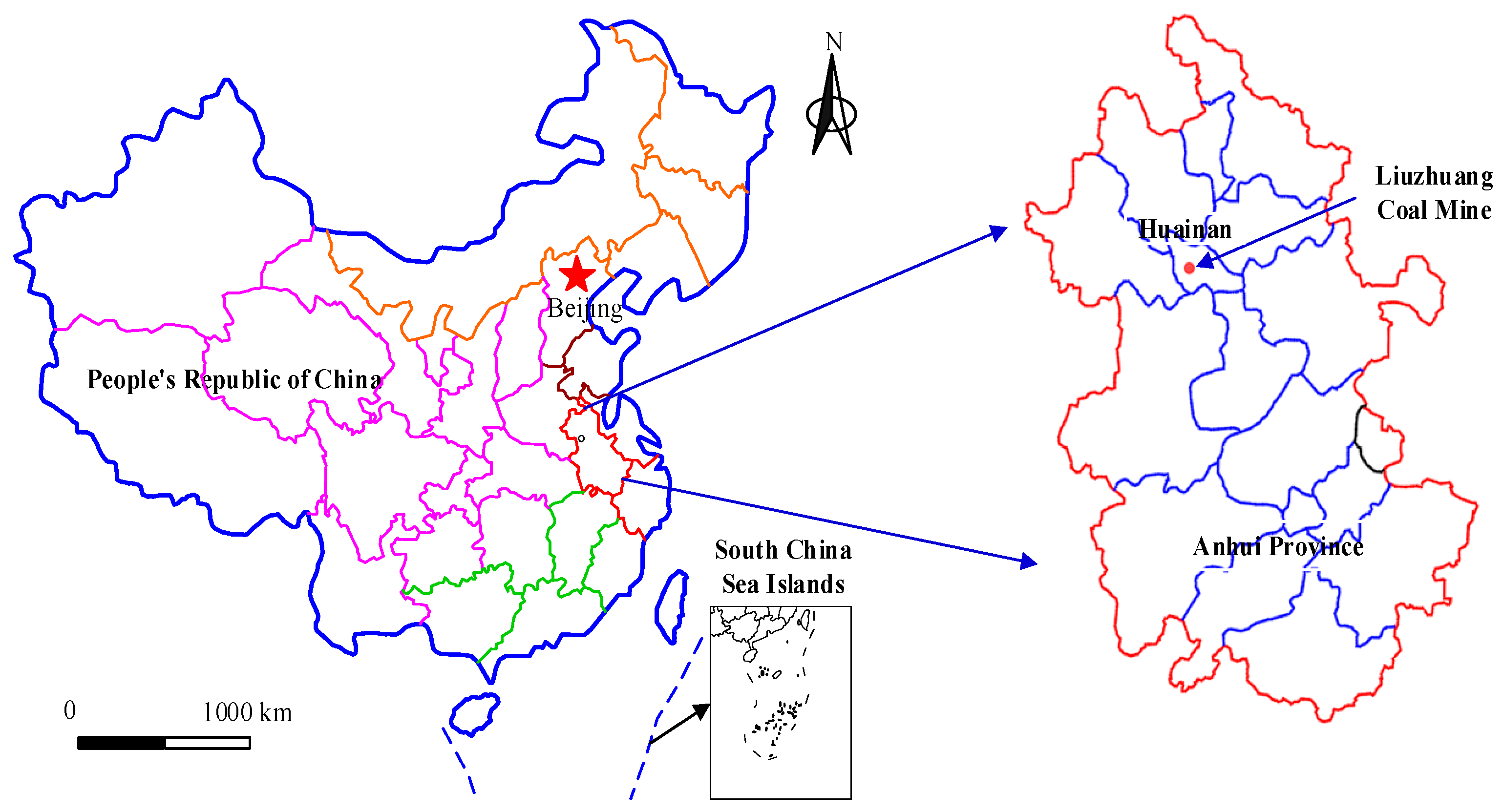
The Liuzhuang Coal Mine is located in the western part of the Huainan Coalfield, with a mining area of approximately 82.2114 km2 and a production capacity of 11 million tons per year (Figure 1). The coalbed gas content in the mining area is relatively low, with an average gas content of 3.2 m3/t. Although the gas content of the mine is relatively small, due to the high mining intensity, the occurrence frequency of the gas concentration exceeding 0.6% in the upper corner of the working face during coal mining is seven times per month. This value makes it very difficult to control gas disasters in the mine. Owing to the low gas content of the mine, facilitating the coalbed gas extraction using the coalbed permeability enhancement method is not effective enough. The coalbed in Liuzhuang Mine is a spontaneous-combustion coalbed, and a short-term air injection will not cause spontaneous combustion of the coal body. Therefore, the efficiency of the coalbed gas extraction can be enhanced by injecting air into the coalbed.

Figure 1.
Location of the Liuzhuang Coal Mine.
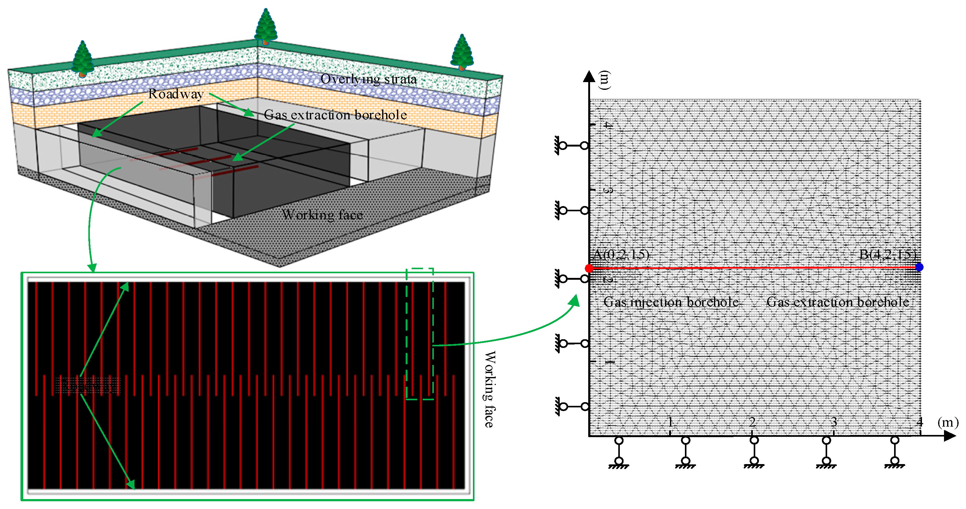
The average thickness of coalbed 11-2 in Liuzhuang Mine is 4.3 m, and the spacing between the underground gas extraction boreholes is 4 m. In this study, the minimum gas extraction unit (two boreholes and their intermediate coal body) was selected for numerical simulation, with a model size of 4 × 4.3 m (Figure 2). The borehole wall was set as Dirichlet boundary conditions, with roller support conditions applied to the surrounding boundary. For the convenience of observing the simulation effect, a reference line A-B is drawn, and the coordinates of point A and point B are (0, 2.15) and (4, 2.15), respectively. The numerical simulation parameters are set according to the geological conditions of the coal and rock in Liuzhuang Mine, with initial gas pressure, temperature, and permeability of 0.45 MPa, 298.5 K, and 9 × 10⁻¹⁷ m2, respectively. Other numerical simulation parameters are listed in Table 1.

Figure 2.
Numerical simulation model.

Table 1.
Numerical simulation parameters.
3.2. The Influence of Air Injection into the Coalbed for Coalbed Gas Extraction
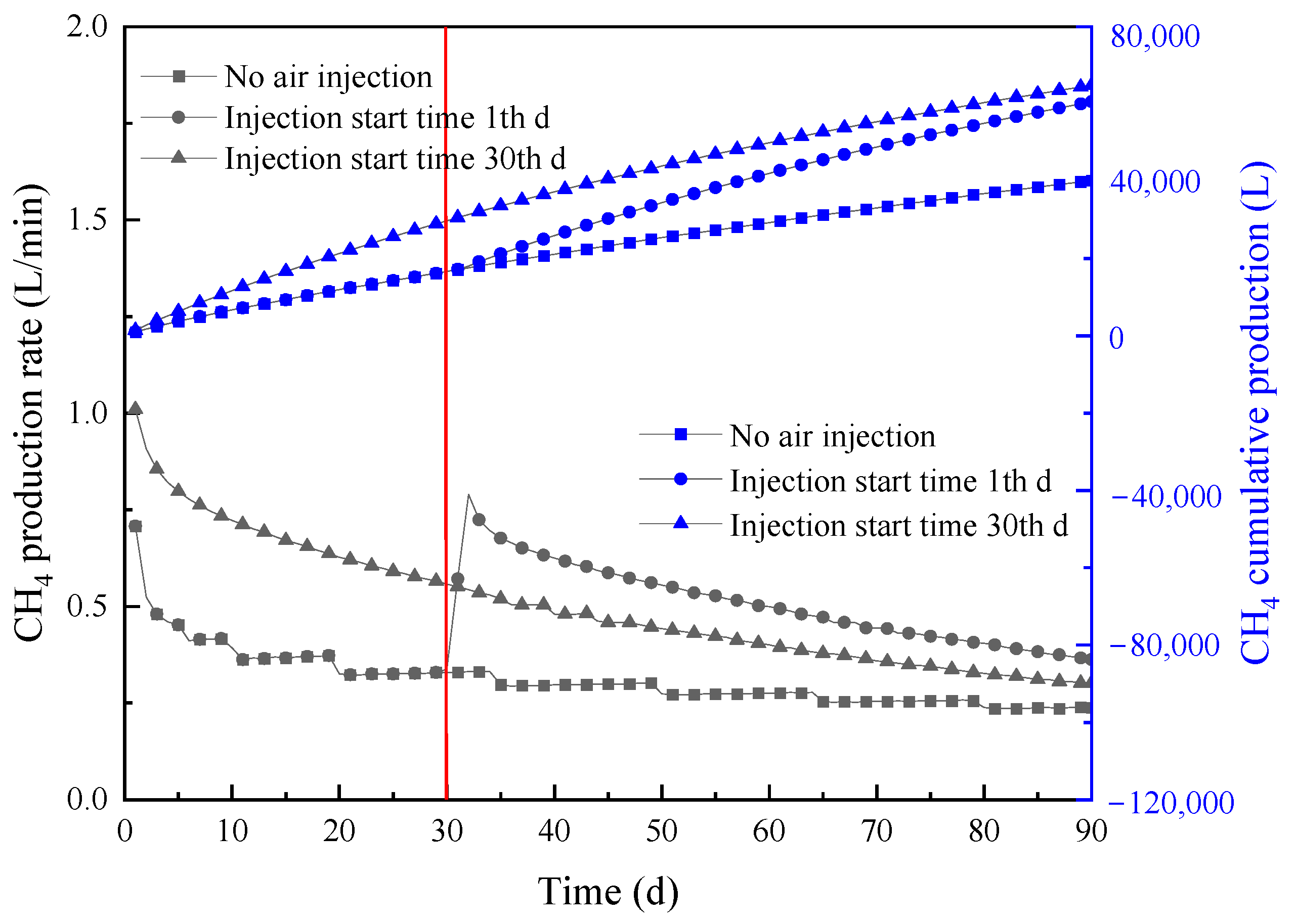
Figure 3 presents the variations in CH4 production rate and cumulative CH4 production under three different conditions: no air injection, injection starts on the first day, and injection starts on the 30th day. As can be seen in Figure 3, when no air is injected into the borehole, the maximum CH4 production rate is only 0.71 L/min. The CH4 production rate rapidly decreased during the extraction process, and the average CH4 production rate after 90 days of extraction was only 0.31 L/min. After 30 days of extraction, 0.6 MPa of air was injected into the gas injection hole, and the CH4 production rate increased rapidly from 0.34 L/min to 0.57 L/min on the day of gas injection, an increase of 67.64%. When air was injected into the coal seam on the day of extraction, the maximum CH4 production rate was 0.72 L/min, which was 132.26% higher than that under the condition of no air injection.

Figure 3.
Variation of CH4 production rate and CH4 cumulative production with time.
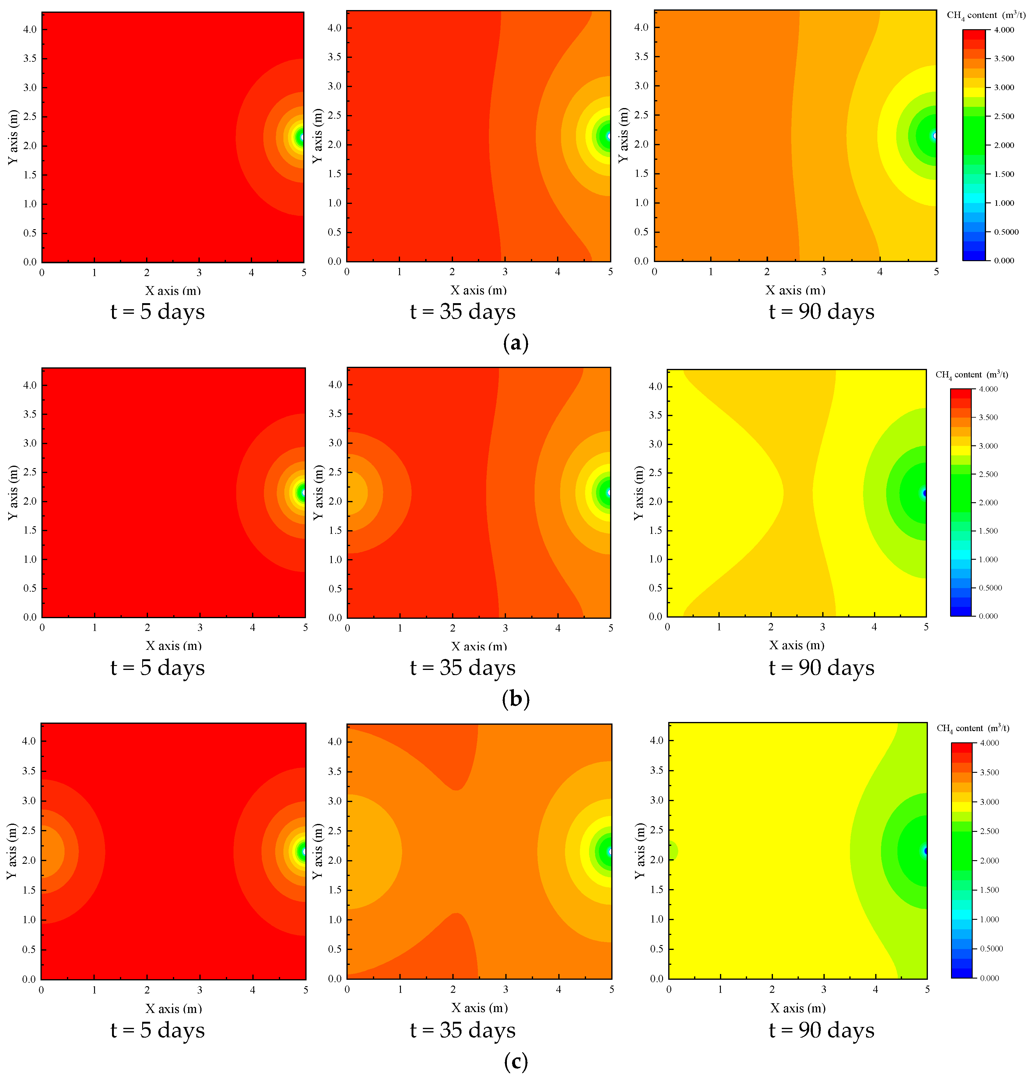
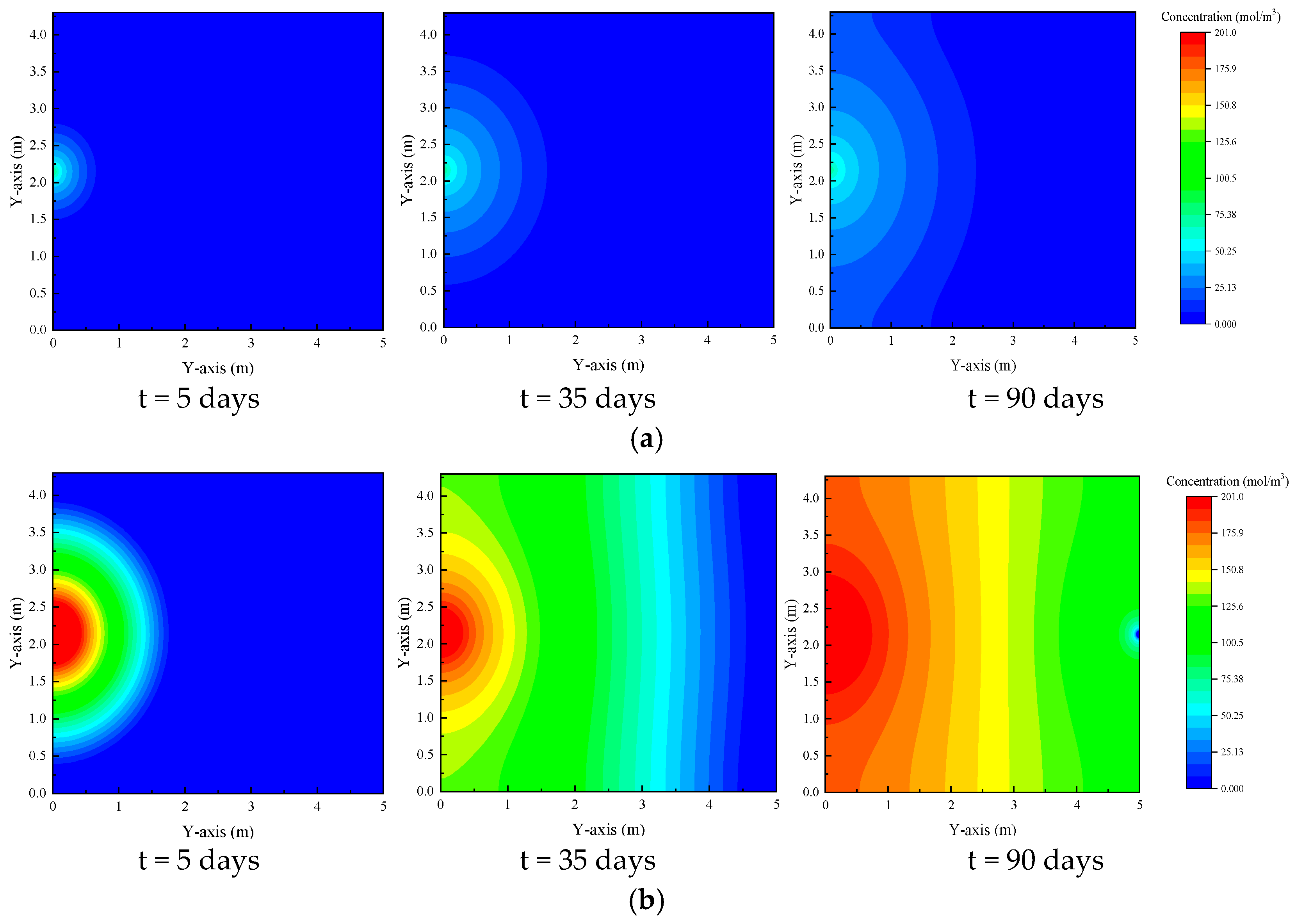
As shown in Figure 4, when air was not injected, the CH4 content in the coalbed decreased slowly. The CH4 content was lowest near the extraction borehole. When the extraction time was 90 days, the maximum CH4 content in the coalbed was 3.47 m3/t. When air was injected into the coalbed 30 days after extraction, a large reduction zone of CH4 content was formed near the injection borehole, and the CH4 content in the entire coalbed extraction area was significantly reduced. When the extraction time was 90 days, the maximum CH4 content in the coal seam was 3.08 m3/t. When air was injected into the injection borehole at the beginning of the extraction project, when the extraction time was 90 days, the maximum CH4 content in the coal seam was only 2.96 m3/t, which is far less than that of the above two conditions. The injection of high-pressure air into the coalbed cannot only promote CH4 desorption but also increase the migration speed of CH4 in the coalbed and improve the efficiency of coalbed gas extraction in the extraction borehole.

Figure 4.
The distributions of CH4 content under different air injection conditions: (a) No air injection, (b) Injection start time: day 1, and (c) Injection start time: day 30.
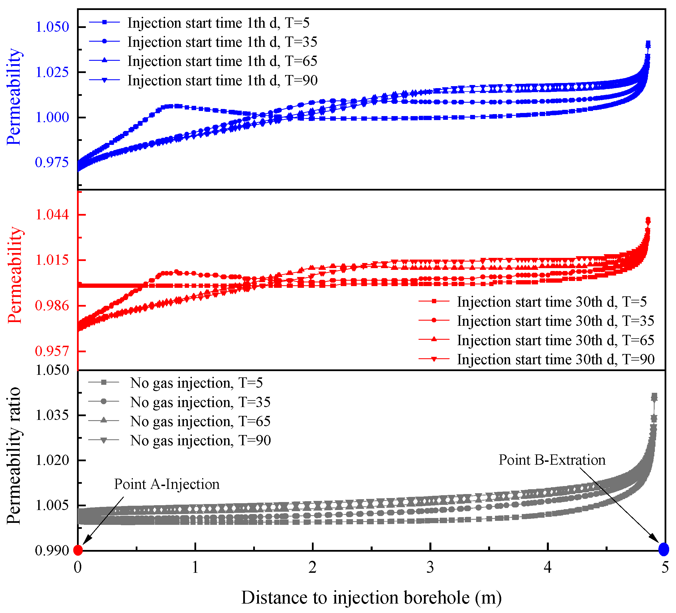
Figure 5 shows the variation of permeability under different air injection conditions. As illustrated in Figure 5, when there was no air injected into the coalbed, the permeability of the coalbed continuously increased slightly during gas drainage. This is because gas desorption shrinks the coal skeleton, increasing the coal porosity and permeability. When air was injected into the coalbed, the adsorption capacity of O2 in the air was greater than that of CH4, and the coal skeleton expanded after absorbing O2, resulting in a rapid decrease in the permeability of the coal body. The decrease in coalbed permeability was closely related to the amount of air injection. When the air injection time was 90 d, the permeability of the coalbed near the gas injection port increased to the original 97.43% (Figure 6).

Figure 5.
Variation of permeability on reference line A-B under different air injection conditions.

Figure 6.
Effect of Air-ECGE on coalbed permeability on reference line A-B.
3.3. Effect of Injection Pressure on Air-ECGE
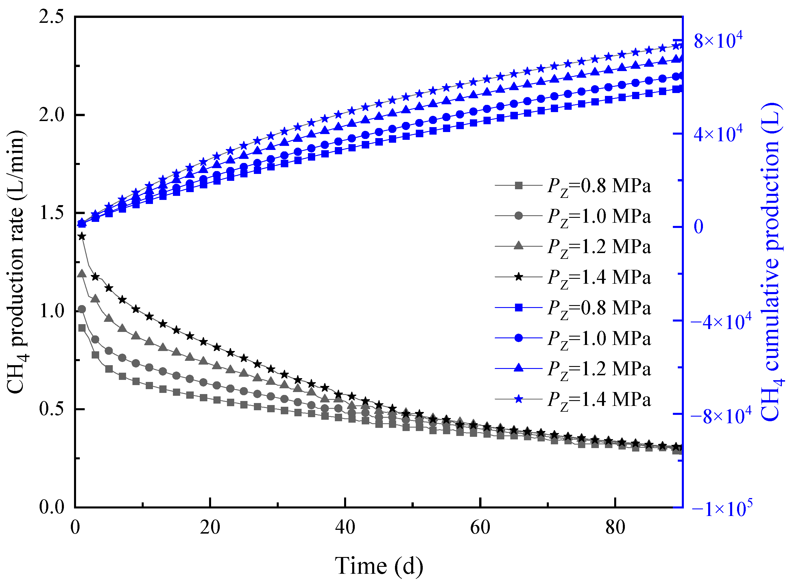
As shown in Figure 7, the CH4 production rate increased with the increase in injection pressure. After 90 days of extraction, the CH4 production rate decreased by 68.54%, 70.14%, 74.41%, and 77.73% when the air injection pressures were 0.8 MPa, 1.0 MPa, 1.2 MPa, and 1.4 MPa, respectively. Setting the injection pressure Pz = 1.0 MPa as a reference, the cumulative production of CH4 at Pz = 1.0 MPa, 1.2 MPa, and 1.4 MPa after extraction for 90 days increased by 9.03%, 21.26%, and 31.08%, respectively.

Figure 7.
Variation of CH4 production rate and CH4 cumulative production under varying injected air pressures.
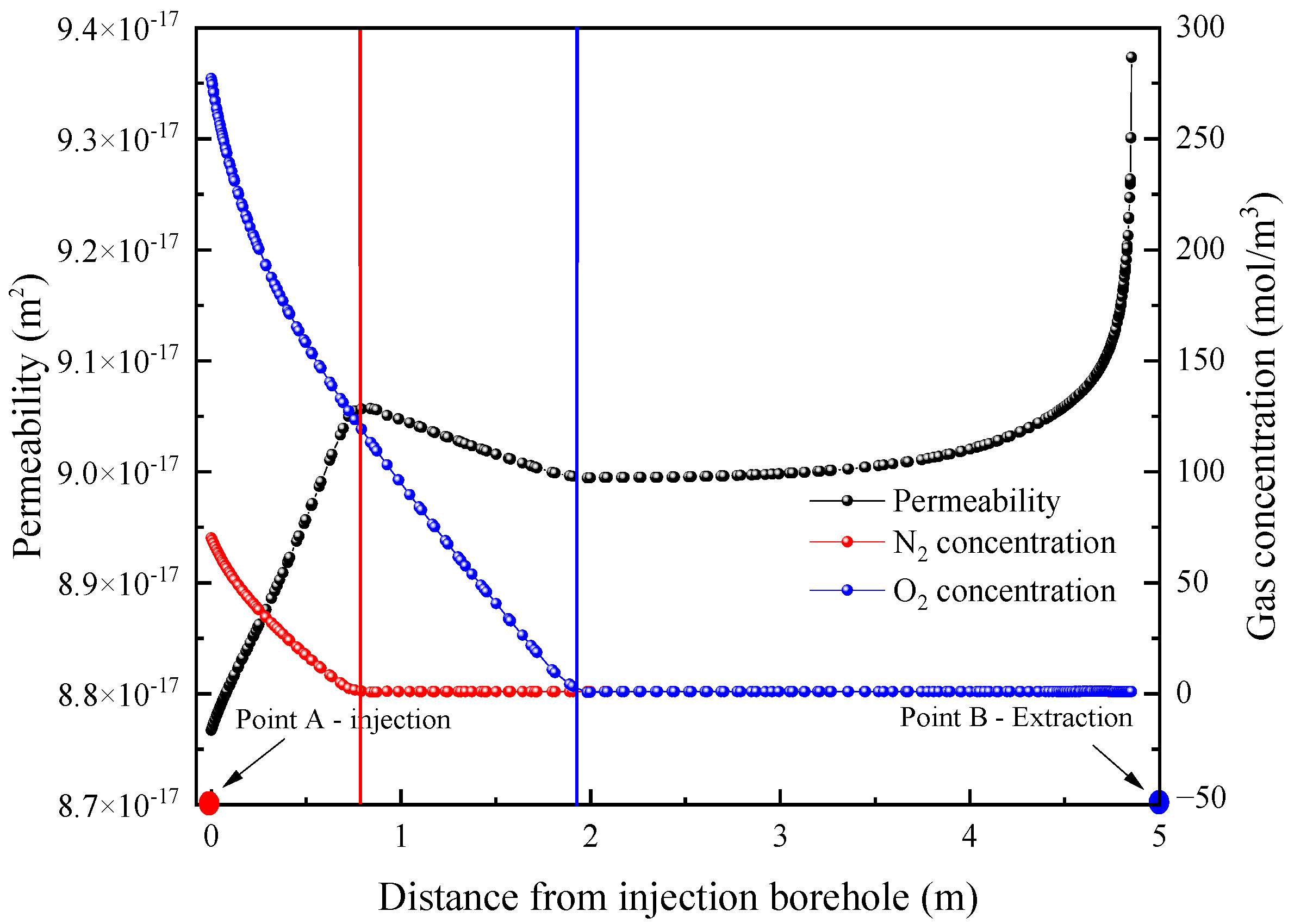
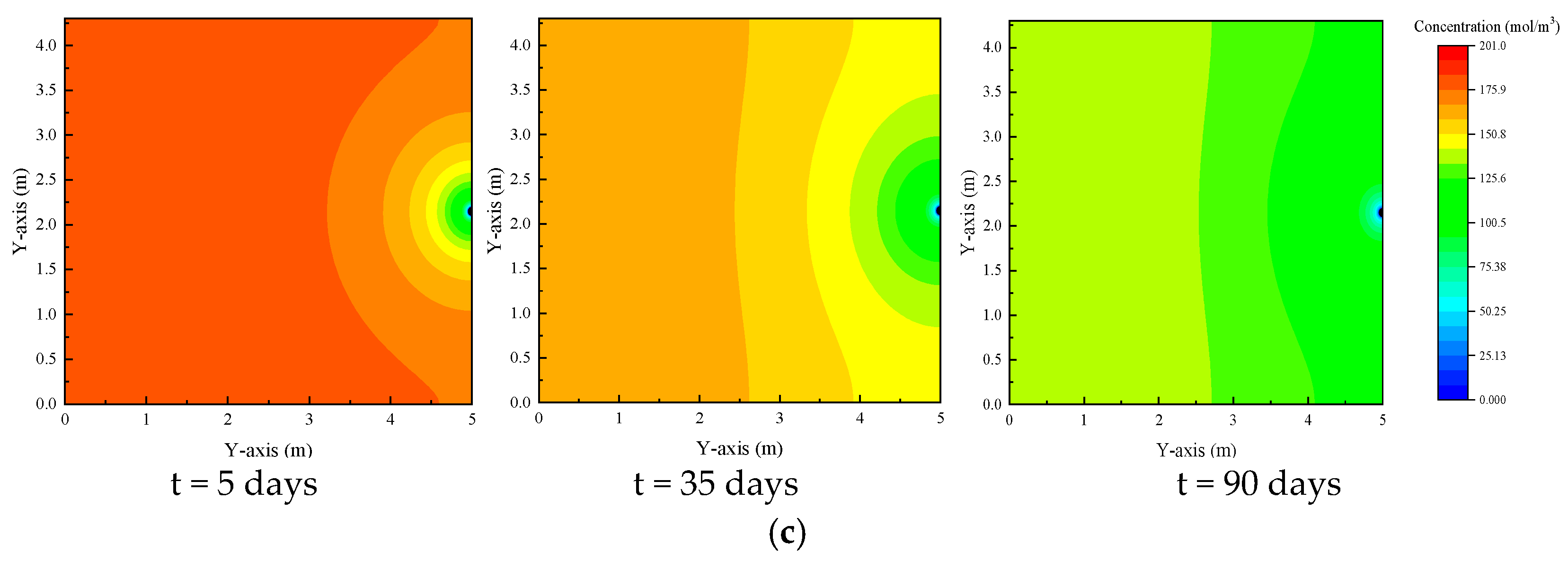
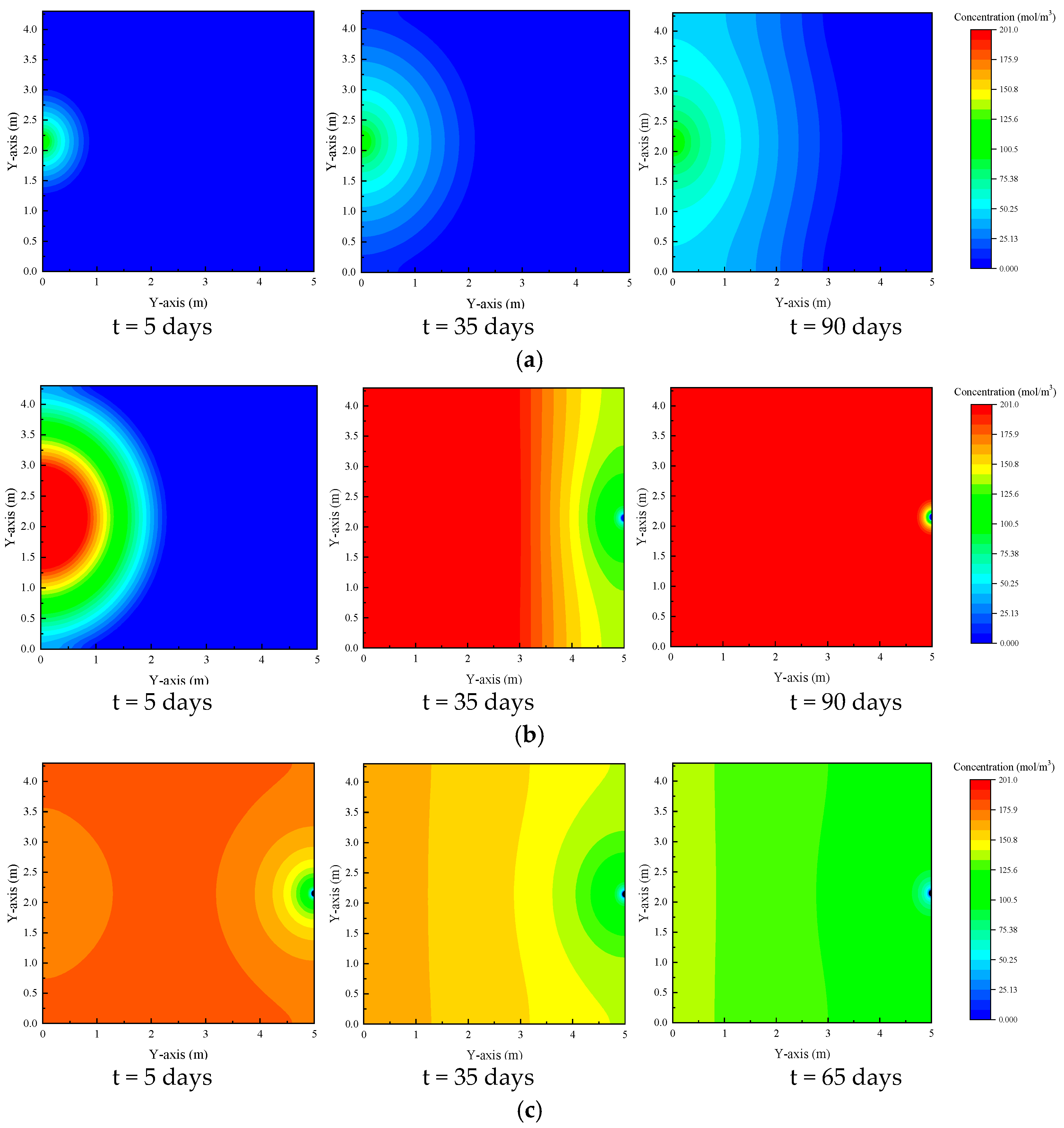
As shown in Figure 8 and Figure 9, under the influence of air injection, the CH4 concentration significantly decreased near the gas injection borehole in the early stages of the coalbed gas extraction, and the range of CH4 concentration reduction was generally the same as the range of N2 migration. The migration of N2 promotes the migration of CH4 and reduces the concentration of CH4 in the area. When the gas injection pressure increased from 0.8 MPa to 1.4 MPa, it significantly increased the driving force of gas in the coalbed. However, due to the low O2 content in the air, after 90 days of air injection, O2 still did not break through to the extraction borehole. The injection pressure increased from 0.8 MPa to 1.4 MPa, and the average O2 concentration in the coalbed increased by 98.31%.


Figure 8.
Gas concentration in coal when injection pressure Pz = 0.8 MPa; (a) O2 concentration, (b) N2 concentration, and (c) CH4 concentration.

Figure 9.
Gas concentration in coal when injection pressure Pz = 1.4 MPa; (a) O2 concentration, (b) N2 concentration, and (c) CH4 concentration.
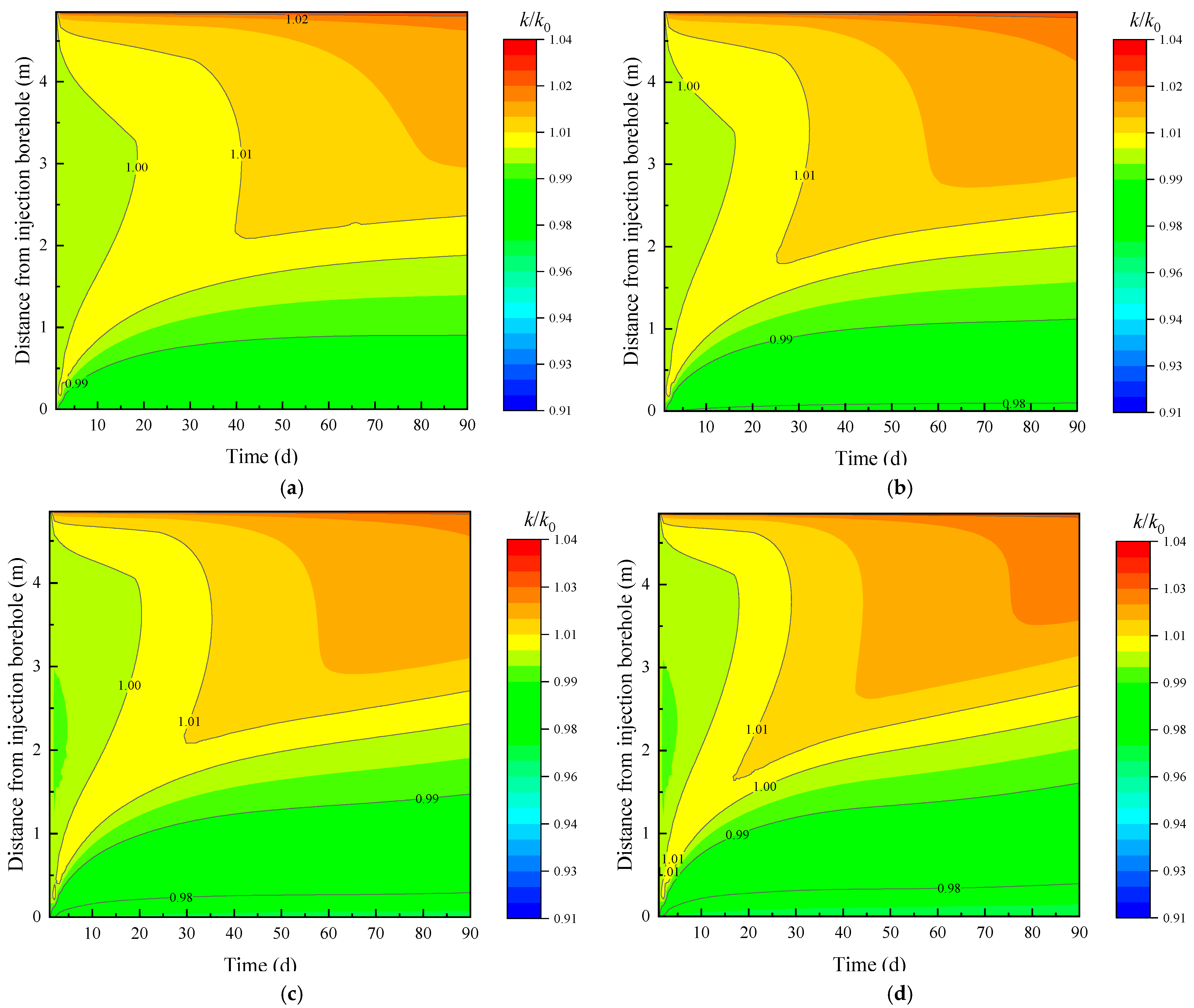
Figure 10 shows the evolution of the permeability ratio on line A-B with varying injected air pressures. As illustrated in the figure, the area of coal permeability reduction near the gas injection borehole increased with time, and the permeability of the coal near the extraction borehole showed a trend of first increasing and then decreasing. The higher the air injection pressure, the greater the increase in permeability of the coal near the extraction borehole. After 90 days of extraction, the decrease in permeability of the coal near the gas injection borehole became more prominent. This is because increasing the air injection pressure facilitates the CH4 extraction and the entry of more N2 into the coal, which significantly increases the coal seam permeability. More O2 is also injected into the coalbed, and when it migrates to the extraction borehole, the permeability of the coal near the area will decrease significantly.

Figure 10.
Evolution of permeability ratio on line A-B with varying injected air pressures; (a) PZ = 0.8 MPa, (b) PZ = 1.0 MPa, (c) PZ = 1.2 MPa, and (d) PZ = 1.4 MPa.
3.4. Effect of Borehole Spacing on Air-ECGE
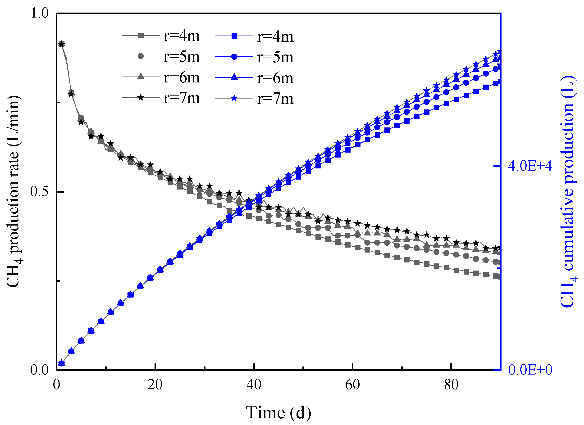
As shown in Figure 11, the CH4 production rate of the extraction borehole was generally the same under different borehole spacing conditions in the early stages of the coalbed CH4 extraction. As the extraction progressed, the closer the borehole spacing, the lower the CH4 production rate. There are two reasons for this phenomenon: first, the larger the borehole spacing, the more CH4 sources are controlled by a single borehole; second, the smaller the borehole spacing, the more accelerated the breakthrough of air, affecting the CH4 production rate. After 90 days of extraction, when the borehole spacing r = 4 m, 5 m, 6 m, and 7 m, the cumulative CH4 production was 56,614.29 L, 59,477.14 L, 61,297.14 L, and 62,485.71 L, respectively. Setting the drilling spacing r = 4 m as a reference, the cumulative gas production rate of r = 5 m, 6 m, and 7 m was increased by 5.06%, 8.27%, and 10.37%, respectively.

Figure 11.
Variation of CH4 production rate and CH4 cumulative production under different borehole spacings.
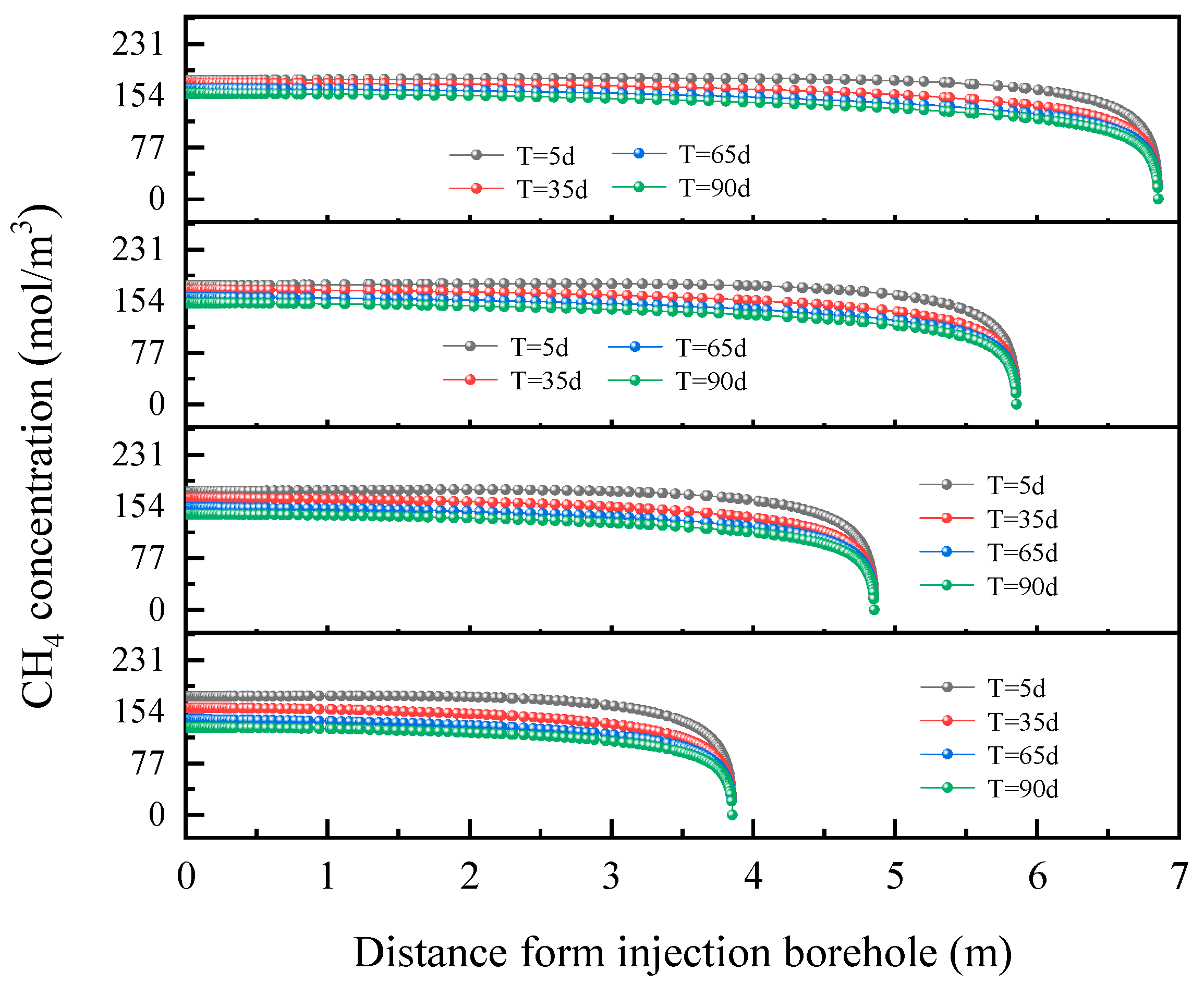
As shown in Figure 12, there was only a slight difference in CH4 concentration in the coalbed during the initial stage of extraction. However, as the extraction project progressed, the smaller the spacing between boreholes, the more significant the decrease in CH4 concentration in the coalbed. After 90 days of extraction, when the borehole spacing r = 4 m, 5 m, 6 m, and 7 m, the maximum CH4 concentrations in the coalbed were 130.32 mol/m3, 142.04 mol/m3, 150.83 mol/m3, and 157.43 mol/m3, respectively. Setting the borehole spacing r = 4 m as a reference, the maximum CH4 concentrations of the coalbed for r = 5 m, 6 m, and 7 m were increased by 9.00%, 15.73%, and 39.12%, respectively.

Figure 12.
Variation of CH4 concentration on reference line A-B.
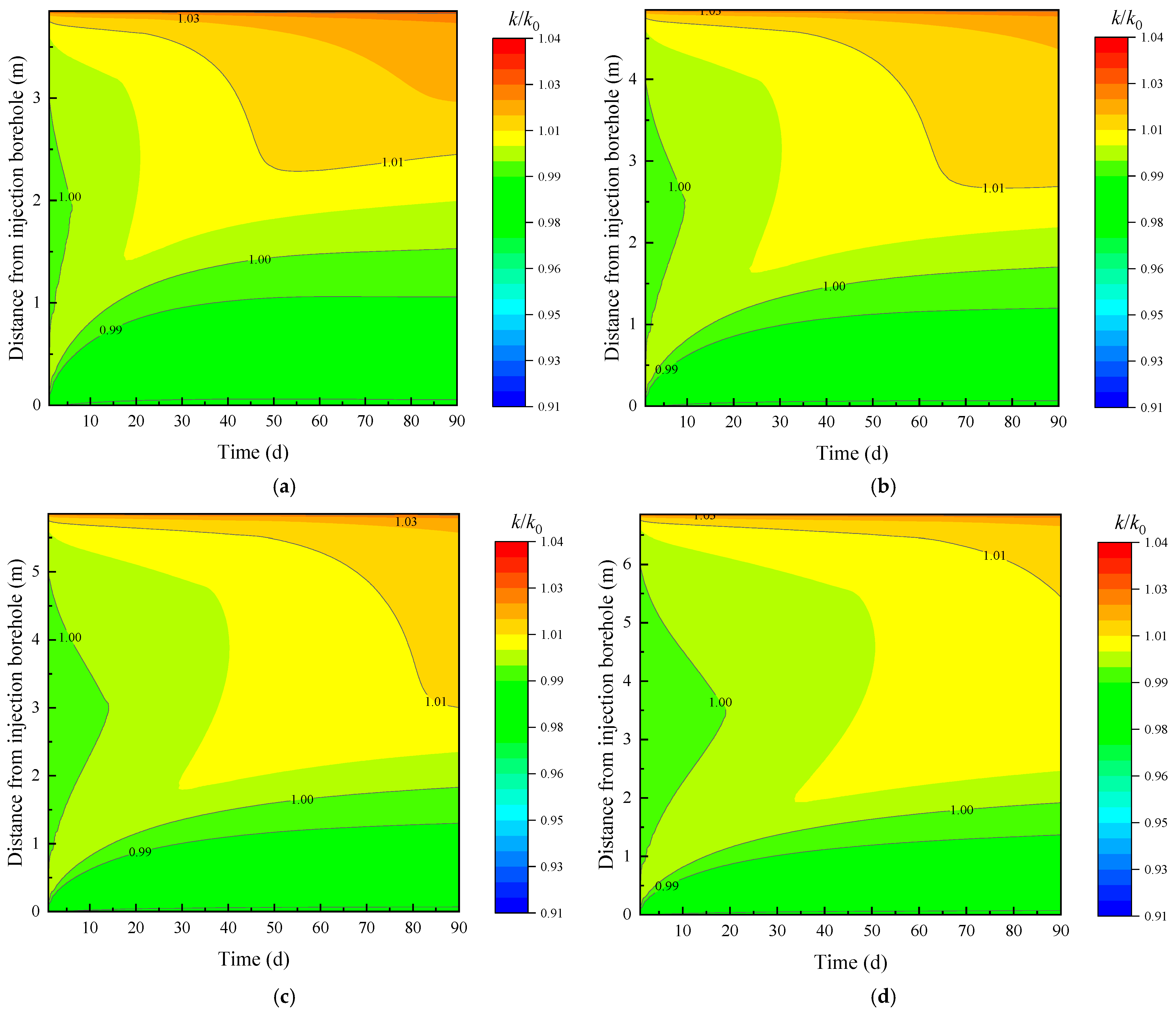
Figure 13 shows the evolution of the permeability ratio on line A-B with varying borehole spacing. As illustrated in the figure, the larger the spacing between boreholes, the higher the gas content in the coalbed after 90 days of extraction, and the smaller the increase in coal permeability near the extraction boreholes. The area of reduced permeability near the gas injection well is related to the migration of O2. The greater the borehole spacing, the less the area near the extraction hole is affected by O2, and the higher the permeability.

Figure 13.
Evolution of permeability ratio on line A-B with varying borehole spacing; (a) r = 4 m, (b) r = 5 m, (c) r = 6 m, and (d) r = 7 m.
4. Field Test of Air-ECGE in Liuzhuang Mine
To verify the effectiveness of Air-ECGE, an underground Air-ECGE engineering test was conducted in the Liuzhuang Coal Mine (Figure 14). A total of six test boreholes were considered, of which 1# and 2# were air injection boreholes, and 1-1#, 1-2#, 2-1#, and 2-2# were extraction boreholes. The final spacing of the boreholes was 4 m, and the gas injection pressure during the test was 0.8 MPa.

Figure 14.
Schematic diagram of field test.
As shown in Figure 15, after injecting air into the coalbed, the extraction flow rapidly increased. The flow rate of borehole 1-2# was 0.48 L/min before injecting air into the coalbed but increased to 12.00 L/min after injecting gas into the coalbed, which is an increase of 24.2 times. The gas extraction flow rate of the four extraction boreholes increased significantly after gas injection, with the gas extraction flow rates of the 1-1#, 2-1#, and 2-2# boreholes increasing by 4.13 times, 18.97 times, and 10.44 times, respectively, after air injection into the coalbed. Clearly, injecting high-pressure air into the coalbed accelerated the migration of gas within the coal, and the flow rate of the extraction boreholes increased significantly. The variation trend of the flow rate of the gas extraction boreholes in the same group was generally the same, which is closely related to the efficiency of injecting air into the gas injection holes.


Figure 15.
Variation of extraction flow with time; (a) 1-1# borehole, (b) 1-2# drill hole, (c) 2-1# borehole, and (d) 2-2# borehole.
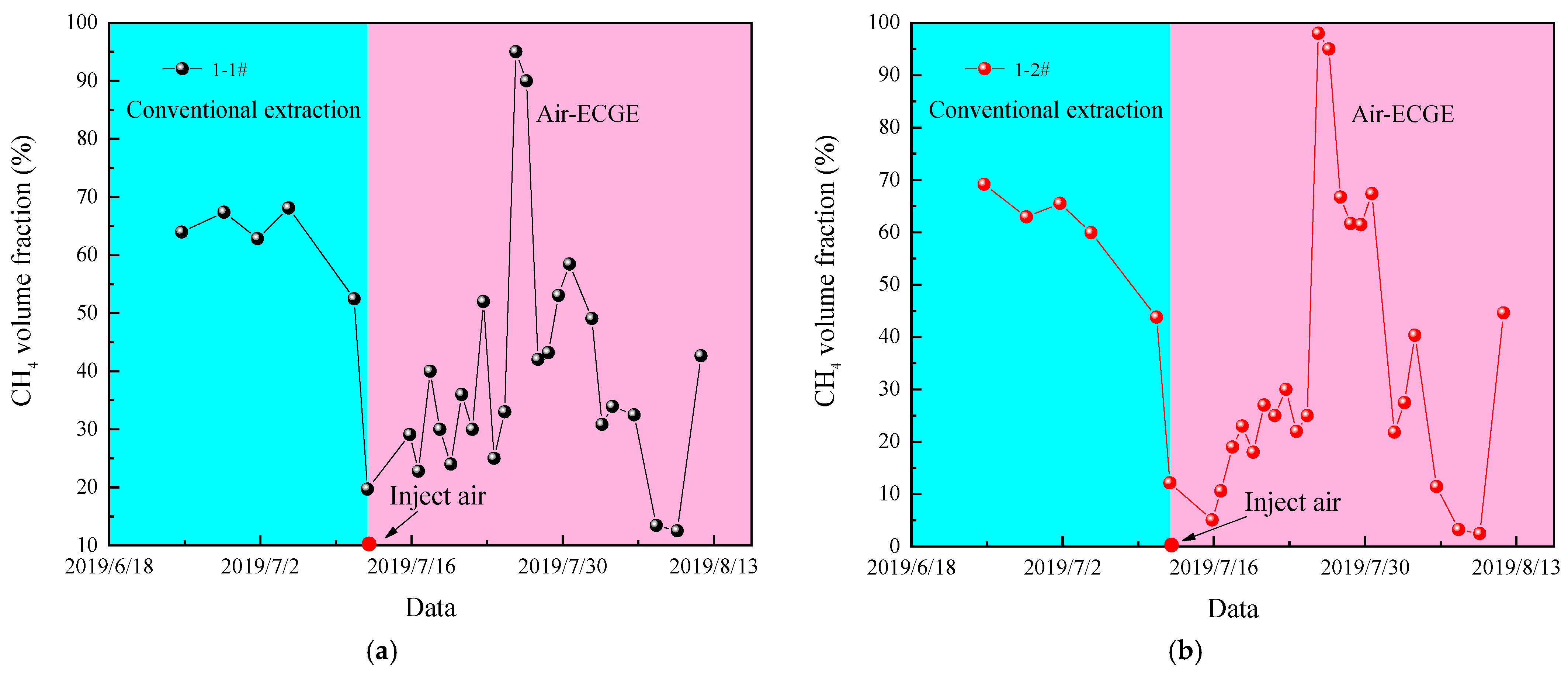
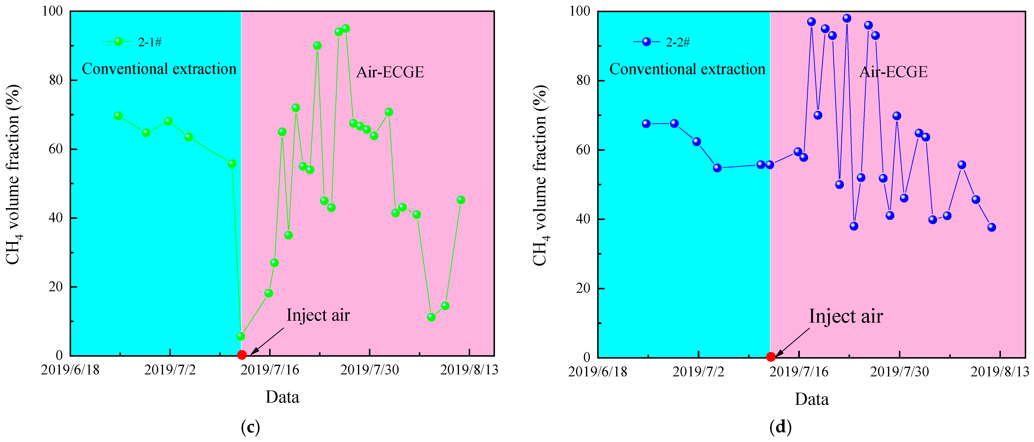
As shown in Figure 16, the volume fraction of CH4 in the extraction borehole decreased rapidly after injecting air into the coalbed. This is because air quickly penetrates the extraction borehole, increasing the extraction flow rate of the borehole and reducing the extraction concentration of the borehole. The air breakthrough occurred on the same day mainly because of the close location of the borehole opening. Since no gas injection was performed between 25 July and 30 July, the extraction drill hole had a large CH4 volume fraction during this period. The CH4 volume fraction of the 2-2# drill hole increased significantly during the initial gas injection period, indicating that air had not yet penetrated the drill hole. This was mainly due to the deviation of the drilling trajectory, which put the 2-2# borehole far away from the gas injection drill hole. After air breakthrough, the CH4 volume fraction of the borehole decreased significantly.


Figure 16.
Variation of CH4 volume fraction with time; (a) 1-1# borehole, (b) 1-2# borehole, (c) 2-1# borehole, and (d) 2-2# borehole.
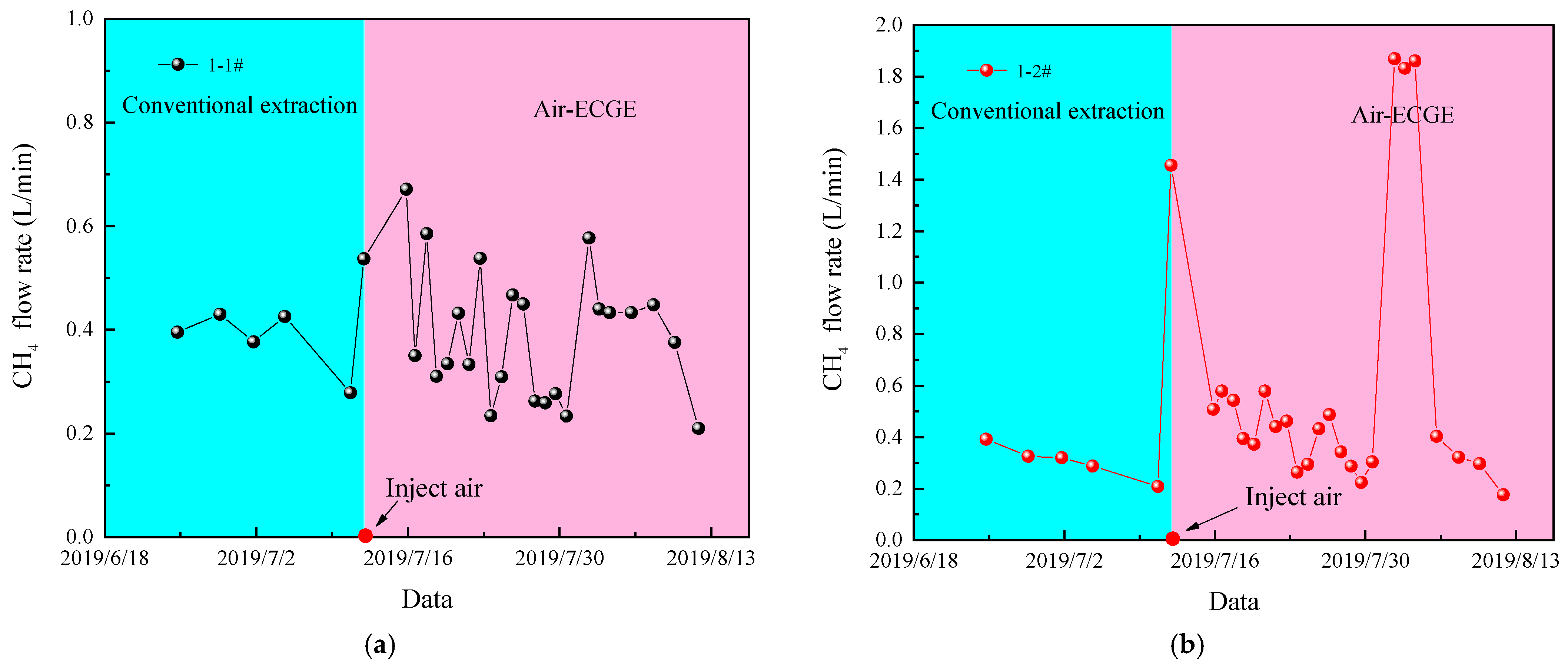
Figure 17 illustrates the changes in CH4 flow rate in the extraction borehole. As illustrated in the figure, the injection of air significantly increased the CH4 extraction rate. Before the air injection into the coalbed, the CH4 extraction flow rate of the 1-2# borehole was 0.331 L/min, but after the injection, it rose to 3.344 L/min, an increase of 9.10 times. After the air injection, the average CH4 extraction rate of the 1-1#, 1-2#, 2-1#, and 2-2# boreholes increased by 3.82%, 100.19%, 60.72%, and 49.68%, respectively. Under conventional extraction conditions, the CH4 extraction rate decreases with time, but by injecting air into the coalbed, the CH4 extraction rate can be significantly increased. During the period from 25 July to 30 July, the CH4 extraction rate of each borehole that had not yet been injected with air was still greater than the CH4 extraction rate before injection. This observation indicates that the effect of injecting air on facilitating coalbed CH4 extraction has a certain lag effect and does not disappear immediately after stopping injection.


Figure 17.
Variation of CH4 flow rate with time; (a) 1-1# borehole, (b) 1-2# borehole, (c) 2-1# drill hole, and (d) 2-2# drill hole.
5. Discussion
Based on the above analysis, the impact of air injection on coalbed gas extraction can be divided into two stages:
- (1)
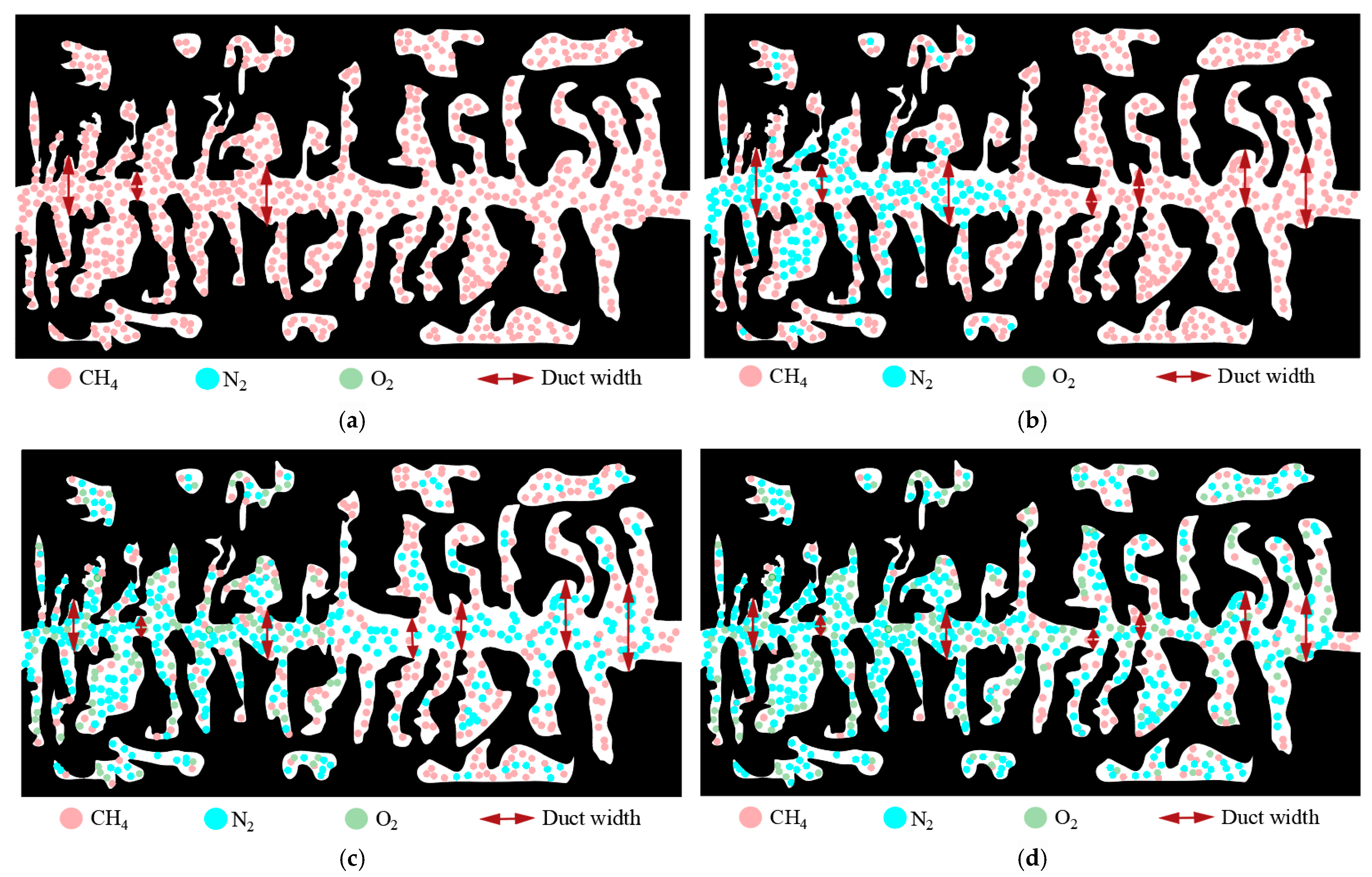
- Owing to the high content of N2 in the air and the relatively low adsorption capacity of N2 on coal, the migration speed of N2 inside the coal is faster than that of O2, and the coal around the gas injection borehole is first affected by N2. High-pressure N2 compresses the coal skeleton, increasing the width of the coal duct and the permeability. Moreover, high-pressure N2 increases the internal pressure difference of the coal body, promotes gas migration, and increases the extraction efficiency of methane (Figure 18a,b).
 Figure 18. Principle diagram of Air-ECGE; (a) Unaffected by air, (b) Affected by N2, (c) O2 starts to affect, and (d) CH4 further reduced.
 - (2)
- When O2 affects the coal body, owing to the strong adsorption of O2 on the coal body, the coal skeleton expands, the pores of the coal body become smaller, and the permeability decreases. However, O2 can displace more CH4, further promoting the extraction of coalbed methane (Figure 18c,d).
- (3)
- As shown in previous studies focusing on surface well coalbed methane drainage, the injection gas pressure typically exceeds 6 MPa. In contrast, this field test achieved effective results with only 0.8 MPa injection pressure. The key reason lies in the substantial difference in well spacing: surface operations require 100–300 m between injection and production wells, whereas coal mine underground drilling allows a spacing of merely 1–6 m between boreholes. This compact configuration enables efficient gas drainage with lower pressure. Although studies indicate higher injection pressures enhance drainage effectiveness, China’s underground air compressors are restricted to a maximum outlet pressure of 2.5 MPa per safety regulations, with pipeline pressure typically maintained below 1.0 MPa. This critical safety measure prevents gas leaks from endangering personnel in underground workings.
- (4)
- Not all areas within coal mines are suitable for Air-ECGE technology implementation. First, specific coal seam characteristics are a prerequisite: if geological structures are well-developed, it may cause inadvertent connectivity between injection boreholes, extraction boreholes, or underground roadways. This scenario would allow injected gas to flow directly into extraction points or tunnels, significantly compromising its effectiveness in enhancing coal seam gas drainage. Second, regarding underground infrastructure: large-scale implementation requires high-capacity air compressors, which typically exceed 3.5 m in length and 3 tons in weight. Mines must therefore possess adequate transport capacity for such equipment along with sufficient clearance for installation in confined underground spaces.
- (5)
- Since the technology involves injecting high-pressure air into boreholes, its core equipment requirement is specifically air compressors. Currently, certified air compressors suitable for underground coal mine operations carry an approximate price tag of $75,000. Notably, engineering materials employed are standard consumables routinely used in mine production, incurring no significant additional material costs. Mine implementation would require only one additional air compressor operator. Critical safety protocols must be established: Mine operators should enhance underground safety training programs with emphasis on strictly prohibiting unauthorized disconnection of injection pipelines to prevent high-pressure hazards. Furthermore, the efficacy of Air-ECGE technology is highly dependent on optimal borehole design and precise gas injection parameter selection. Consequently, systematic technical training for relevant personnel is imperative, with projected training expenditures estimated at $100,000. Although this technology entails additional costs, it can significantly enhance the efficiency of coalbed methane extraction, ensure production safety during coal mining, reduce accident rates, and improve coal production efficiency in mines. From this perspective, its application ultimately lowers operational costs for mines and enhances corporate profits.
6. Conclusions
In this study, a thermal–hydraulic–solid coupling model for air-enhanced coalbed gas extraction (Air-ECGE) was established. Additionally, the impact of air injection on coalbed methane extraction was simulated, and field experiments were conducted on air injection to enhance gas extraction. The following are the major findings of the study:
- (1)
- The results show that injecting high-pressure air into a coalbed can effectively promote gas desorption and gas migration within the coalbed, greatly improving the efficiency of coalbed gas extraction.
- (2)
- Owing to the large pressure gradient that can lead to fast coalbed gas seepage, the gas production rate of the extraction borehole is directly proportional to the gas injection pressure. The spacing of the boreholes limits the influence range of the gas injection: the larger the spacing, the larger the influence range, and the higher the gas extraction rate of the extraction borehole.
- (3)
- After injecting air into the Liuzhuang coal mine coalbed, the extraction flow rate and concentration of gas from the extraction boreholes both increased significantly. A certain delay effect was observed in the gas injection effect, and the gas extraction flow rate only decreased after a period of time post gas injection stoppage.
- (4)
- This study only conducted field trials of Air-ECGE technology under one borehole layout configuration. However, multiple types of boreholes exist in underground coal mines, such as cross-measure boreholes and long boreholes exceeding 300 m. The effectiveness of Air-ECGE technology under these scenarios requires further investigation. Furthermore, injecting air into coal seams may reduce the methane extraction concentration from underground boreholes. Currently, most mines utilize the extracted methane gas, and a decrease in concentration could impose limitations on its utilization. Therefore, the Air-ECGE process requires further optimization to ensure increased methane extraction while maintaining concentration. Achieving a balance between increasing the absolute methane yield and maintaining extraction concentration constitutes a critical future research direction for this technology.
- (5)
- Due to the O2-rich nature of air, prolonged injection into spontaneous combustion-prone coal seams carries the risk of triggering spontaneous combustion, potentially leading to mine fires. Therefore, ensuring the safety of such coal seams during Air-ECGE application represents a critical research topic for subsequent studies.
Author Contributions
Conceptualization, Y.F. and L.S.; methodology, L.S.; software, Y.F. and H.G.; validation, X.S.; formal analysis, X.S.; investigation, H.G.; resources, L.S.; data curation, H.G.; writing—original draft preparation, Y.F.; writing—review and editing, Y.F.; visualization, H.G.; supervision, Y.F.; project administration, H.G.; funding acquisition, L.S. All authors have read and agreed to the published version of the manuscript.
Funding
This work was financially supported by the National Key R&D Program of China (2023YFC3009001).
Data Availability Statement
The original contributions presented in this study are included in the article. Further inquiries can be directed to the corresponding author.
Conflicts of Interest
Authors Yongpeng Fan, Longyong Shu and Xin Song were employed by the China Coal Research Institute. The remaining author declares that the research was conducted in the absence of any commercial or financial relationships that could be construed as a potential conflict of interest.
References
- Yiting, D. The Coal Industry Structure Is Better and the Background Color Is Greener. People’s Daily, 28 February 2022; 2003–2005. [Google Scholar]
- Guo, Y.; Wang, K.; Du, F.; Guo, H.; Li, K.; Wang, Y. Mechanical-Permeability Characteristics of Composite Coal Rock under Different Gas Pressures and Damage Prediction Model. Phys. Fluids 2024, 36, 1–13. [Google Scholar] [CrossRef]
- Wang, K.; Zhao, E.; Guo, Y.; Du, F.; Ding, K. Effect of Loading Rate on the Mechanical and Seepage Characteristics of Gas-Bearing Coal-Rock and Its Mechanical Constitutive Model. Phys. Fluids 2024, 36, 1–12. [Google Scholar] [CrossRef]
- Shu, L.; Wang, K.; Liu, Z.; Zhao, W.; Zhu, N.; Lei, Y. A Novel Physical Model of Coal and Gas Outbursts Mechanism: Insights into the Process and Initiation Criterion of Outbursts. Fuel 2022, 323, 124305. [Google Scholar] [CrossRef]
- Zhou, F.; Xia, T.; Wang, X.; Zhang, Y.; Sun, Y.; Liu, J. Recent Developments in Coal Mine Methane Extraction and Utilization in China: A Review. J. Nat. Gas Sci. Eng. 2016, 31, 437–458. [Google Scholar] [CrossRef]
- Lin, B.; Zhang, J.; Shen, C.; Zhang, Q.; Sun, C. Technology and Application of Pressure Relief and Permeability Increase by Jointly Drilling and Slotting Coal. Int. J. Min. Sci. Technol. 2012, 22, 545–551. [Google Scholar] [CrossRef]
- Wang, T.; Zhou, W.; Chen, J.; Xiao, X.; Li, Y.; Zhao, X. Simulation of Hydraulic Fracturing Using Particle Flow Method and Application in a Coal Mine. Int. J. Coal Geol. 2014, 121, 1–13. [Google Scholar] [CrossRef]
- Yun, J.; Xu, F.; Liu, L.; Zhong, N.; Wu, X. New Progress and Future Prospects of CBM Exploration and Development in China. Int. J. Min. Sci. Technol. 2012, 22, 363–369. [Google Scholar] [CrossRef]
- Yan, T.; Li, W.; Bi, X. An Experimental Study of Fracture Initiation Mechanisms During Hydraulic Fracturing. Pet. Sci. 2011, 8, 87–92. [Google Scholar] [CrossRef]
- Liu, T.; Lin, B.; Zou, Q.; Zhu, C.; Guo, C.; Li, J. Investigation on Mechanical Properties and Damage Evolution of Coal after Hydraulic Slotting. J. Nat. Gas Sci. Eng. 2015, 24, 489–499. [Google Scholar] [CrossRef]
- Wu, Y.; Liu, J.; Elsworth, D.; Chen, Z.; Connell, L.; Pan, Z. Dual Poroelastic Response of a Coal Seam to CO2 Injection. Int. J. Greenh. Gas Control 2010, 4, 668–678. [Google Scholar] [CrossRef]
- Walker, P.L.; Geller, I. Change in Surface Area of Anthracite on Heat Treatment. Nature 1956, 178, 1001. [Google Scholar] [CrossRef]
- White, C.M.; Smith, D.H.; Jones, K.L.; Goodman, A.L.; Jikich, S.A.; LaCount, R.B.; DuBose, S.B.; Ozdemir, E.; Morsi, B.I.; Schroeder, K.T. Sequestration of Carbon Dioxide in Coal with Enhanced Coalbed Methane Recovery—A Review. Energy Fuels 2005, 19, 659–724. [Google Scholar]
- Bai, X.; Zhang, D.; Zeng, S.; Zhang, S.; Wang, D.; Wang, F. An Enhanced Coalbed Methane Recovery Technique Based on CO2 Phase Transition Jet Coal-Breaking Behavior. Fuel 2020, 265, 2–3. [Google Scholar] [CrossRef]
- Zheng, S.; Yao, Y.; Elsworth, D.; Liu, D.; Cai, Y. Dynamic Fluid Interactions during CO2-Enhanced Coalbed Methane and CO2 Sequestration in Coal Seams. Part 1: CO2-CH4 Interactions. Energy Fuels 2020, 34, 8274–8282. [Google Scholar] [CrossRef]
- Fan, N.; Wang, J.; Deng, C.; Fan, Y.; Mu, Y.; Wang, T. Numerical Study on Enhancing Coalbed Methane Recovery by Injecting N2/CO2 Mixtures and Its Geological Significance. Energy Sci. Eng. 2020, 8, 1104–1119. [Google Scholar] [CrossRef]
- Perera, M.S.A.; Ranjith, P.G.; Ranathunga, A.S.; Koay, A.Y.J.; Zhao, J.; Choi, S.K. Optimization of Enhanced Coal-Bed Methane Recovery Using Numerical Simulation. J. Geophys. Eng. 2015, 12, 90–107. [Google Scholar] [CrossRef]
- Ross, H.E.; Hagin, P.; Zoback, M.D. CO2 Storage and Enhanced Coalbed Methane Recovery: Reservoir Characterization and Fluid Flow Simulations of the Big George Coal, Powder River Basin, Wyoming, USA. Int. J. Greenh. Gas Control 2009, 3, 773–786. [Google Scholar] [CrossRef]
- Hamelinck, C.N.; Faaij, A.P.C.; Turkenburg, W.C.; van Bergen, F.; Pagnier, H.J.M.; Barzandji, O.H.M.; Wolf, K.H.A.A.; Ruijg, G.J. CO2 Enhanced Coalbed Methane Production in the Netherlands. Energy 2002, 27, 647–674. [Google Scholar] [CrossRef]
- Vishal, V.; Mahanta, B.; Pradhan, S.P.; Singh, T.N.; Ranjith, P.G. Simulation of CO2 Enhanced Coalbed Methane Recovery in Jharia Coalfields, India. Energy 2018, 159, 1185–1194. [Google Scholar] [CrossRef]
- Wong, S.; Law, D.; Deng, X.; Robinson, J.; Kadatz, B.; Gunter, W.D.; Ye, J.; Feng, S.; Fan, Z. Enhanced Coalbed Methane and CO2 Storage in Anthracitic Coals—Micro-Pilot Test at South Qinshui, Shanxi, China. Int. J. Greenh. Gas Control 2007, 1, 215–2228. [Google Scholar] [CrossRef]
- Zhou, F.; Hou, W.; Allinson, G.; Wu, J.; Wang, J.; Cinar, Y. A Feasibility Study of ECBM Recovery and CO2 Storage for a Producing CBM Field in Southeast Qinshui Basin, China. Int. J. Greenh. Gas Control 2013, 19, 26–40. [Google Scholar] [CrossRef]
- Fan, Y.; Deng, C.; Zhang, X.; Li, F.; Wang, X.; Qiao, L. Numerical Study of CO2-Enhanced Coalbed Methane Recovery. Int. J. Greenh. Gas Control 2018, 76, 12–23. [Google Scholar] [CrossRef]
- Fan, C.; Elsworth, D.; Li, S.; Chen, Z.; Luo, M.; Song, Y.; Zhang, H. Modelling and Optimization of Enhanced Coalbed Methane Recovery Using CO2/N2 Mixtures. Fuel 2019, 253, 1114–1129. [Google Scholar] [CrossRef]
- Vishal, V.; Ranjith, P.G.; Singh, T.N. CO2 Permeability of Indian Bituminous Coals: Implications for Carbon Sequestration. Int. J. Coal Geol. 2013, 105, 36–47. [Google Scholar] [CrossRef]
- Jasinge, D.; Ranjith, P.G.; Choi, S.K. Effects of Effective Stress Changes on Permeability of Latrobe Valley Brown Coal. Fuel 2011, 90, 1292–1300. [Google Scholar] [CrossRef]
- Zhou, L.; Zhou, X.; Fan, C.; Bai, G. Coal Permeability Evolution Triggered by Variable Injection Parameters during Gas Mixture Enhanced Methane Recovery. Energy 2022, 252, 124065. [Google Scholar] [CrossRef]
- Fan, Z.; Fan, G.; Zhang, D.; Zhang, L.; Zhang, S.; Liang, S.; Yu, W. Optimal Injection Timing and Gas Mixture Proportion for Enhancing Coalbed Methane Recovery. Energy 2021, 222, 119880. [Google Scholar] [CrossRef]
- Mirzaeian, M.; Hall, P.J.; Jirandehi, H.F. Study of Structural Change in Wyodak Coal in High-Pressure CO2 by Small Angle Neutron Scattering. J. Mater. Sci. 2010, 45, 5271–5281. [Google Scholar] [CrossRef]
- Perera, M.S.A.; Ranjith, P.G.; Choi, S.K.; Airey, D.; Weniger, P. Estimation of Gas Adsorption Capacity in Coal: A Review and an Analytical Study. Int. J. Coal Prep. Util. 2012, 32, 25–55. [Google Scholar] [CrossRef]
- Fan, Y.; Shu, L.; Huo, Z.; Hao, J.; Li, Y.; Guo, X. Research on Coalbed Methane Microscopic Seepage Characteristics of Medium and High-Rank Coal. Energy Sources Part A Recovery Util. Environ. Eff. 2021, 1–13. [Google Scholar] [CrossRef]
- Wang, L.; Cheng, Y.; Wang, Y. Laboratory Study of the Displacement Coalbed CH4 Process and Efficiency of CO2 and N2 Injection. Sci. World J. 2014, 242947, 1–9. [Google Scholar] [CrossRef]
- Mazzotti, M.; Pini, R.; Storti, G. Enhanced Coalbed Methane Recovery. J. Supercrit. Fluids 2009, 47, 619–627. [Google Scholar] [CrossRef]
- Balan, H.O.; Gumrah, F. Enhanced Coalbed Methane Recovery with Respect to Physical Properties of Coal and Operational Parameters. J. Can. Pet. Technol. 2009, 48, 56–61. [Google Scholar] [CrossRef]
- Fan, Y.; Deng, C.; Zhang, X.; Li, F.; Wang, X. Numerical Study of Multi-Branch Horizontal Well Coalbed Methane Extraction. Energy Sources Part A Recovery Util. Environ. Eff. 2018, 40, 1342–1350. [Google Scholar] [CrossRef]
- Liu, Y.; Zhang, J.; Wei, J.; Liu, X. Optimum Structure of a Laval Nozzle for an Abrasive Air Jet Based on Nozzle Pressure Ratio. Powder Technol. 2020, 364, 343–362. [Google Scholar] [CrossRef]
- Liu, S.; Ji, H.; Han, D.; Guo, C. Experimental Investigation and Application on the Cutting Performance of Cutting Head for Rock Cutting Assisted with Multi-Water Jets. Int. J. Adv. Manuf. Technol. 2018, 94, 2715–2728. [Google Scholar] [CrossRef]
- Lin, J.; Ren, T.; Wang, G.; Booth, P.; Nemcik, J. Experimental Investigation of N2 Injection to Enhance Gas Drainage in CO2-Rich Low Permeable Seam. Fuel 2018, 215, 665–674. [Google Scholar] [CrossRef]
- Lin, J.; Ren, T.; Cheng, Y.; Nemcik, J.; Wang, G. Cyclic N2 Injection for Enhanced Coal Seam Gas Recovery: A Laboratory Study. Energy 2019, 188, 116115. [Google Scholar] [CrossRef]
- Li-Wei, C.; Tian-Hong, Y.; Hong-Min, Y.; Li-Guo, W. Time Characteristics of the Influence Radius by Injecting N2 to Displace Coalbed Methane: A Case Study. Geofluids 2019, 2019, 1–11. [Google Scholar] [CrossRef]
- Yang, X.; Wang, G.; Du, F.; Jin, L.; Gong, H. N2 Injection to Enhance Coal Seam Gas Drainage (N2-ECGD): Insights from Underground Field Trial Investigation. Energy 2022, 239, 122247. [Google Scholar] [CrossRef]
- Yıldız, T.D. Loss of Profits Occurring Due to the Halting of Mining Operations Arising from Occupational Accidents or Reasons Related to Legislation. Gospod. Surowcami Miner./Miner. Resour. Manag. 2021, 37, 153–176. [Google Scholar] [CrossRef]
- Kahraman, M.M. Analysis of Mining Lost Time Incident Duration Influencing Factors Through Machine Learning. Min. Metall. Explor. 2021, 38, 1031–1039. [Google Scholar] [CrossRef]


Disclaimer/Publisher’s Note: The statements, opinions and data contained in all publications are solely those of the individual author(s) and contributor(s) and not of MDPI and/or the editor(s). MDPI and/or the editor(s) disclaim responsibility for any injury to people or property resulting from any ideas, methods, instructions or products referred to in the content. |
© 2025 by the authors. Licensee MDPI, Basel, Switzerland. This article is an open access article distributed under the terms and conditions of the Creative Commons Attribution (CC BY) license (https://creativecommons.org/licenses/by/4.0/).