1. Introduction
Global environmental issues require the metallurgical industry to move toward improving its sustainability. One of the main challenges is the high carbon intensity of the industry, resulting from the use of large volumes of coke and coal as reducing agents, which leads to a significant carbon footprint, particularly pronounced in the production of chromium-containing alloys.
The main source of chromium is chromite FeO·Cr
2O
3. While industrial processes typically employ chromite ore (FeO·Cr
2O
3) rather than pure chromium oxide, the reduction of chromite proceeds primarily through the stepwise reduction of its Cr
2O
3 component. The reduction of Cr
2O
3 begins at around 1200 °C under laboratory conditions (oxide–graphite powders mixture with argon purging) [
1], and this reaction, in a simplified form, can be presented as follows:
The reaction is endothermic and requires heat input for its active course [
1,
2]. Moreover, such a low-temperature reduction of Cr
2O
3 to any significant extent requires long holding times and a high dispersion of oxide and carbon particles due to several limitations, in particular, diffusion (carbide/metal layers) [
1,
3]. Therefore, in industry, FeCr is obtained at significantly higher temperatures, 1600–1700 °C [
4], which ensure a negative ΔG and a shift in equilibrium toward the metal. Another important aspect is an excess of carbon to ensure an optimal ratio of CO/CO
2 gases in the gas phase toward carbon monoxide, which facilitates the reduction of metals. The required temperatures are achieved in electric furnaces using electric power, where about 3000–4700 kWh are consumed per 1 ton of alloy [
4,
5,
6,
7]. This energy allows for the formation of a liquid alloy, in which Cr
2O
3 is reduced by the carbon dissolved in the melt. A higher carbon content promotes more active reduction by increasing the reduction rate and driving the reaction equilibrium toward metal formation [
8].
In FeCr metallurgy, metallurgical coke is mainly used as a carbon source, characterized by a high carbon content, low ash content, and high mechanical strength, but high cost, scarcity, and a high carbon footprint. This has led to the consideration of alternatives, in the form of semi-coke, anthracite, coal, biochar, and other carbon sources [
9,
10,
11].
The process of chromium reduction with carbon is accompanied by the formation of a significant amount of carbon monoxide (CO) and the subsequent emission of carbon dioxide (CO
2). According to stoichiometric calculations, 1 kg of Cr accounts for 1.27 kg of CO
2. On an industrial scale, the figures are significantly higher, reaching 3.3–10.3 kgCO
2-eq/kg Cr, with 1.8–5.5 kgCO
2-eq/kg FeCr due to emissions from heating, reductions in impurities, the combustion of carbon in electrodes, etc. [
7,
10]. Such a wide range reflects differences in technologies and energy sources. Older technologies that use coal-fired electricity result in values closer to the upper limit. In contrast, modern closed furnaces equipped with gas capture systems and powered by renewable energy can achieve values near the lower limit.
The carbothermic process has historically been the primary method and is characterized by high energy consumption (up to 4700 kWh/t) and substantial direct carbon emissions (up to 5.5 tCO
2-eq/t FeCr). Alternative methods of obtaining chromium (metallothermic) do not directly emit CO
2; these include aluminothermy and silicothermy. However, aluminum production is extremely energy-intensive (alumina electrolysis), and aluminothermy is ecologically feasible only if cheap “green” aluminum is available [
12,
13]. Ferrosilicon production requires considerable coke input, and when evaluating the full life cycle, substituting carbon with silicon may not decrease emissions and, in some cases, may even lead to higher CO
2 emissions. For instance, 1 ton of liquid FeCr produces about 1.3 tons of CO
2, compared to up to 3.6 tons for 1 ton of liquid FeSi65 [
14,
15]. A promising alternative is the use of the complex ferroalloy FeAlSiCa, produced from waste materials, including blast furnace slag from ArcelorMittal Temirtau (now Qarmet, Kazakhstan) and high-ash coal from the Saryadyr deposit in Kazakhstan. The coal exhibits an ash content of up to 55%, and the total reserves are estimated at 175 million tons. The production cost of FeAlSiCa is approximately 40–50% lower than that of commercial SiCa alloy or mechanically blended mixtures of SiCa with secondary aluminum [
16]. The use of waste and substandard raw materials as the feedstock and reducing agent simultaneously helps to solve the problems of their processing when obtaining FeAlSiCa [
17,
18].
The average composition of FeAlSiCa is as follows (%): 8–15 Ca, 42–53 Si, 17–24 Al, and balance Fe. Each leading element has a high reducing potential. The effectiveness of reducing agents in high-temperature metallurgical processes is best evaluated using thermodynamic data, specifically the Gibbs free energy of oxide formation as a function of temperature. This relationship is commonly illustrated in Ellingham diagrams, which plot the ΔG◦ versus temperature for oxidation reactions. At the elevated temperatures relevant to ferrochrome smelting (~1500 °C), the position of each element’s oxidation line indicates its relative affinity for oxygen.
According to the Ellingham diagram, calcium, aluminum, and silicon exhibit high oxygen affinities at 1500 °C. Their relative reducing strengths follow the order Ca > Al > Si.
This ordering reflects the increasingly negative ΔG° values for the formation of CaO, Al2O3, and SiO2 at smelting temperatures. Therefore, calcium is the most powerful reducing agent in the system, followed by aluminum and silicon. These thermodynamic properties explain the effective performance of the FeAlSiCa alloy (FASC) at reducing Cr2O3 under the experimental conditions.
An analysis of the thermodynamic calculations shows that for the reduction of Cr
2O
3 at a temperature of 1500 °C, the ΔG for Ca, Al, and Si is about −620, −540, and −310 kJ/mol, respectively. Based on this, the prospects for using FeAlSiCa as a reducing agent are obvious and are due to the possibility of exothermic self-sustaining reactions [
19,
20,
21].
The ΔG for carbon under similar conditions is −114 kJ/mol; the affinity for oxygen is lower than that of the elements in the composition of FeAlSiCa.
FeAlSiCa, due to its high reducing capabilities, is proposed for use to obtain chromium-containing ferroalloys. Additionally, the use of FeSiCr dusts, which arise as a result of crushing and fractionating FeSiCr, is promising as a reducing agent. Such dust is typically not utilized due to its fine particle size and low mass, which results in loss through exhaust systems during handling. The concentration of silicon in its composition is quite high, and chromium can easily pass into the metal.
The purpose of this work is to study the possibility of obtaining a chromium-containing ferroalloy characterized by a low, close-to-zero carbon footprint, in terms of its direct CO2 emissions using FeAlSiCa and FeSiCr dust.
Although previous studies have explored the metallothermic reduction of chromium, the use of waste-derived complex alloys, such as FeAlSiCa, remains insufficiently studied. The combined effect of Ca, Al, and Si on chromite reduction is not well understood. This work aims to evaluate the effectiveness of FeAlSiCa and FeSiCr as carbon-free reductants, analyze the resulting metal and slag, and determine the optimal conditions for producing low-carbon ferrochrome.
2. Materials and Methods
Table 1,
Table 2 and
Table 3 present the chemical compositions of chrome concentrate, FeAlSiCa, and FeSiCr dust, respectively, which were used in this work for smelting FeCr. The chemical composition of the listed materials was determined using classical analytical chemistry methods.
Lime, with a purity of CaO ≥ 92% (SiO2 ≤ 1.8%, S ≤ 0.03%, P ≤ 0.02%, and calcination loses ≤ 6%), was also introduced in a proportion of 1.8 CaO per 1 SiO2 formed as a result of smelting to bind Si, P, and S impurities.
FeAlSiCr and FeSiCr dust were used in equal proportions (1:1) in four variants: 10% deficiency of reducing agents (batch 1); a stoichiometric amount sufficient for complete reduction of the main oxides of Cr concentrate (batch 2); and with 10% (batch 3) and 20% (batch 4) excess. A more detailed composition is presented below:
- -
Batch 1, %: 52.3 Cr concentrate; 7.8 FeAlSiCr; 7.8 FeSiCr dust; and 31.9 lime;
- -
Batch 2, %: 44.7 Cr concentrate; 8.9 FeAlSiCr; 8.9 FeSiCr dust; and 37.4 lime;
- -
Batch 3, %: 39.0 Cr concentrate; 9.7 FeAlSiCr; 9.7 FeSiCr dust; and 41.4 lime;
- -
Batch 4, %: 34.6 Cr concentrate; 10.3 FeAlSiCr; 10.3 FeSiCr dust; and 44.6 lime.
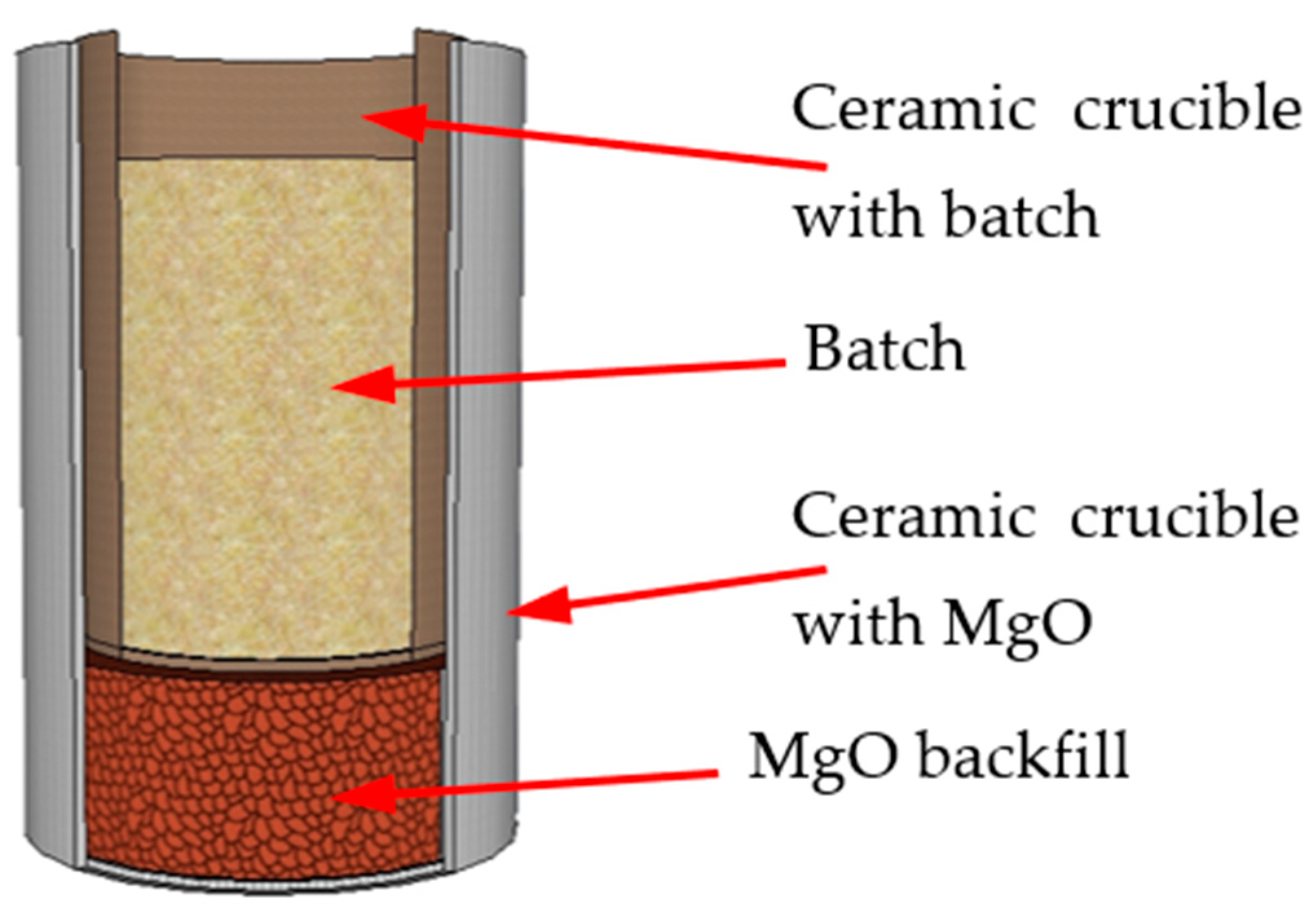
Melting was carried out in ceramic crucibles (99.5% Al2O3) immersed in a MgO backfill (to protect the furnace working space from possible splashes as a result of violent exothermic reactions), in a chamber furnace in an air atmosphere at a heating rate of 10 °C/min with isothermal holding at 1650 °C for 30 min, with further cooling in the furnace to room temperature. The batch was loaded in the form of mixtures of crushed powders with particles ≤ 120 μm in size.
Figure 1 shows the schematic of the batch loading into the furnace.
The obtained metal and slag samples were examined using a ZepTools ZEM20 (ZEPTOOLS, China) scanning electron microscope (SEM) with an Oxford energy-dispersive spectroscopy (Oxford Instruments, UK) (EDS) attachment. Individual elements (C, S, P, and N) were examined using analytical chemistry methods. X-ray diffraction (XRD) phase analysis of the metal and slag samples was carried out using an Empyrean diffractometer (PANalytical, the Netherlands), with subsequent phase identification performed using Match! (version 4.1) software (Crystal Impact). A copper anode was used.
3. Results
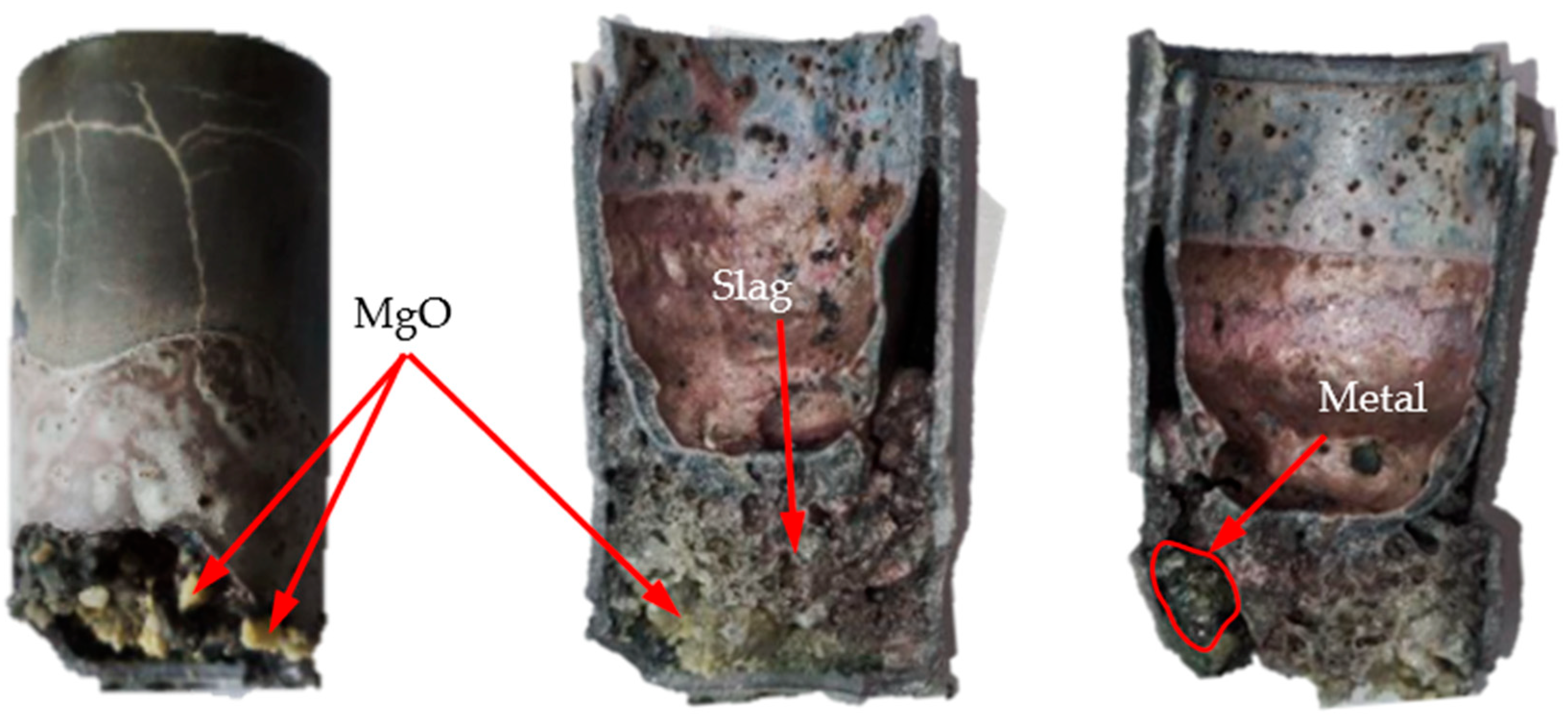
As a result of smelting, slag sintering on the walls of the ceramic crucible was observed, which somewhat complicated the removal of the smelting products from the crucible. Moreover, the partial destruction of the crucible was observed, which led to the interaction of the slag with the MgO backfill. However, the metal was separated from the slag quite easily. In order to determine the purity of the obtained metal and slag samples, sections of them were obtained for SEM examination.
Figure 2 shows the typical appearance of the crucibles after smelting.
For each metallic sample, to ensure a representative analysis, several solidified metal particles were extracted from the crucible after cooling. For the slag analysis, portions were chosen from visually clean regions where no apparent fused crucible fragments or MgO backfill material contamination was observed. The samples were mounted in conductive resin and subsequently ground to obtain a flat and polished surface suitable for the microstructural analysis.
3.1. Metal Study
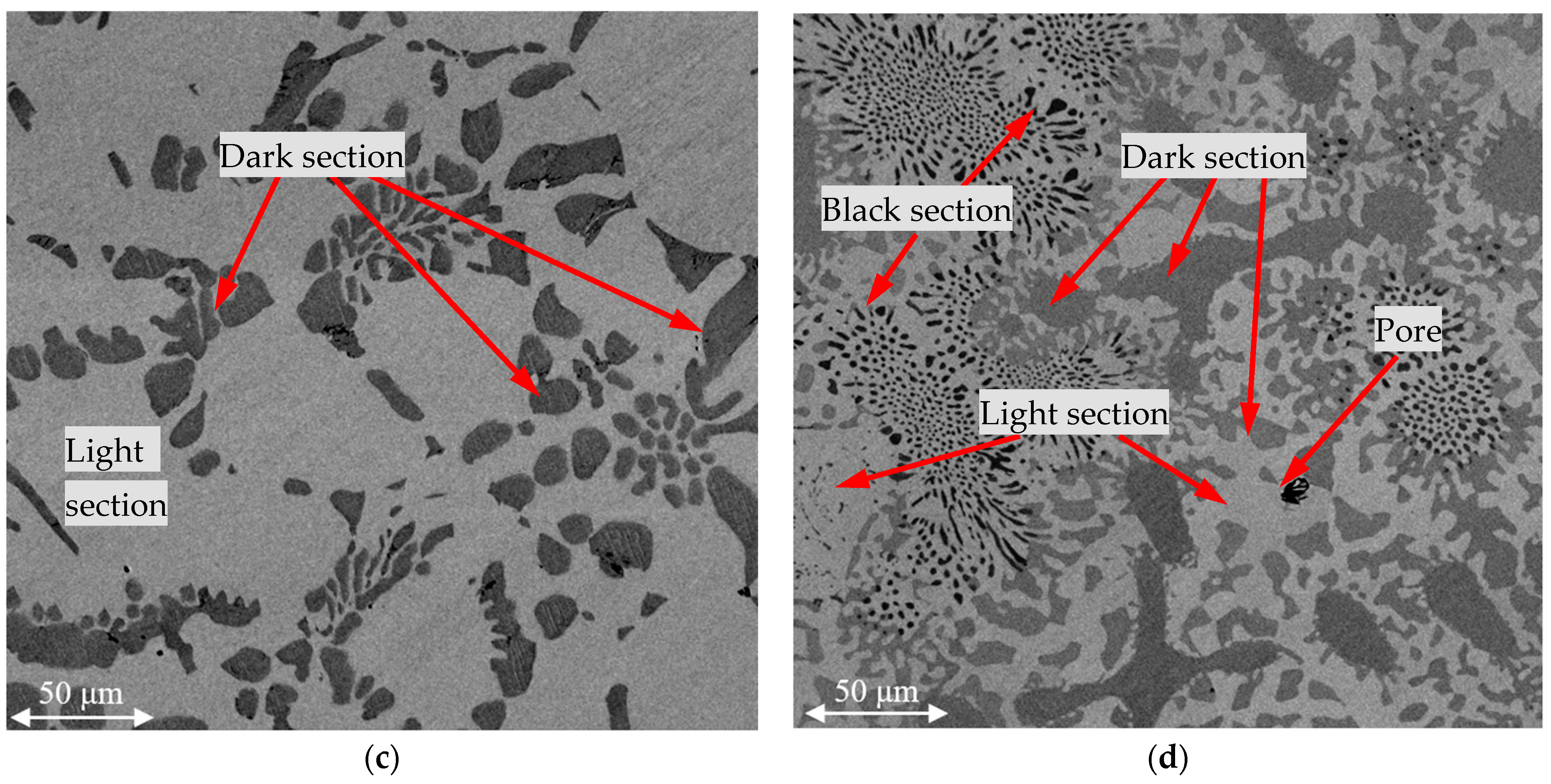
Figure 3 shows the SEM images of the metals obtained as a result of smelting using the four batches that introduced FeAlSiCa and FeSiCr dust. The images were obtained using the backscattered electron detection mode at a magnification of ×1000.
The figure shows that in all cases, two main phases were formed, and there were three in batch 4. According to the average EDS results for the light and dark areas (
Table 4), the light area was a phase with a smaller amount of chromium, while in the dark area the proportion of chromium was higher. Another feature of the dark phase was also the presence of nitrogen or silicon in its composition.
Table 4 also presents the EDS results for the analysis of the total spectra of the entire observed images.
Comparing the characteristic microstructures of the studied samples and their composition according to the EDS results, it can be concluded that the metal samples obtained with batches 1–3 for introducing the reducing agents consisted of two phases: a light solid solution of Cr-Fe and a dark one based on the nitrides in the Cr-V-N system. In batch 4, silicides were also formed in the Cr-Si system (Cr3Si and Cr5Si3) doped with Fe, which is explained by the excess of Si, the source of which were the reducing agents.
Analyzing the data on the total spectra, as can be seen from
Table 4, a higher chromium content was observed with batches 1 and 2.
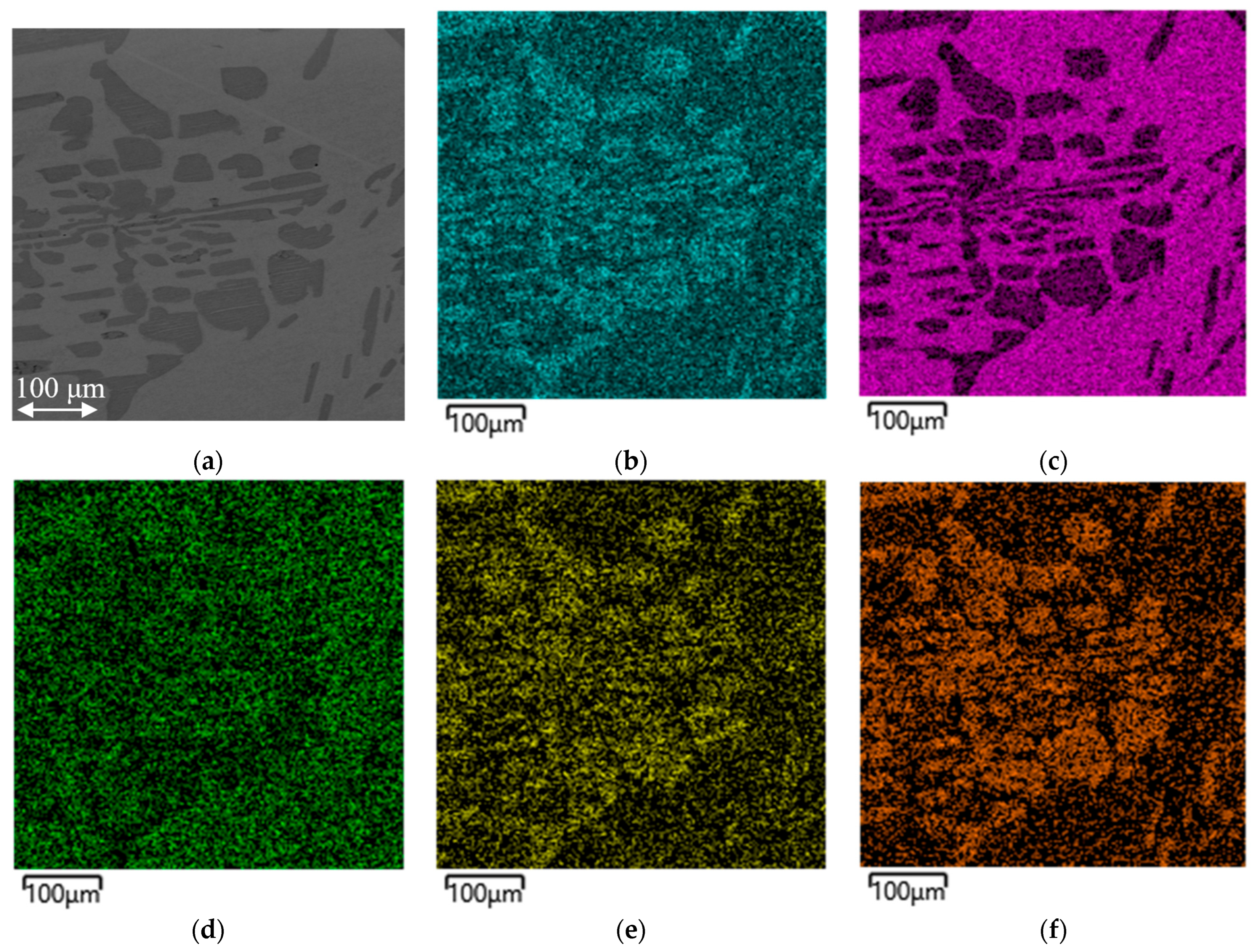
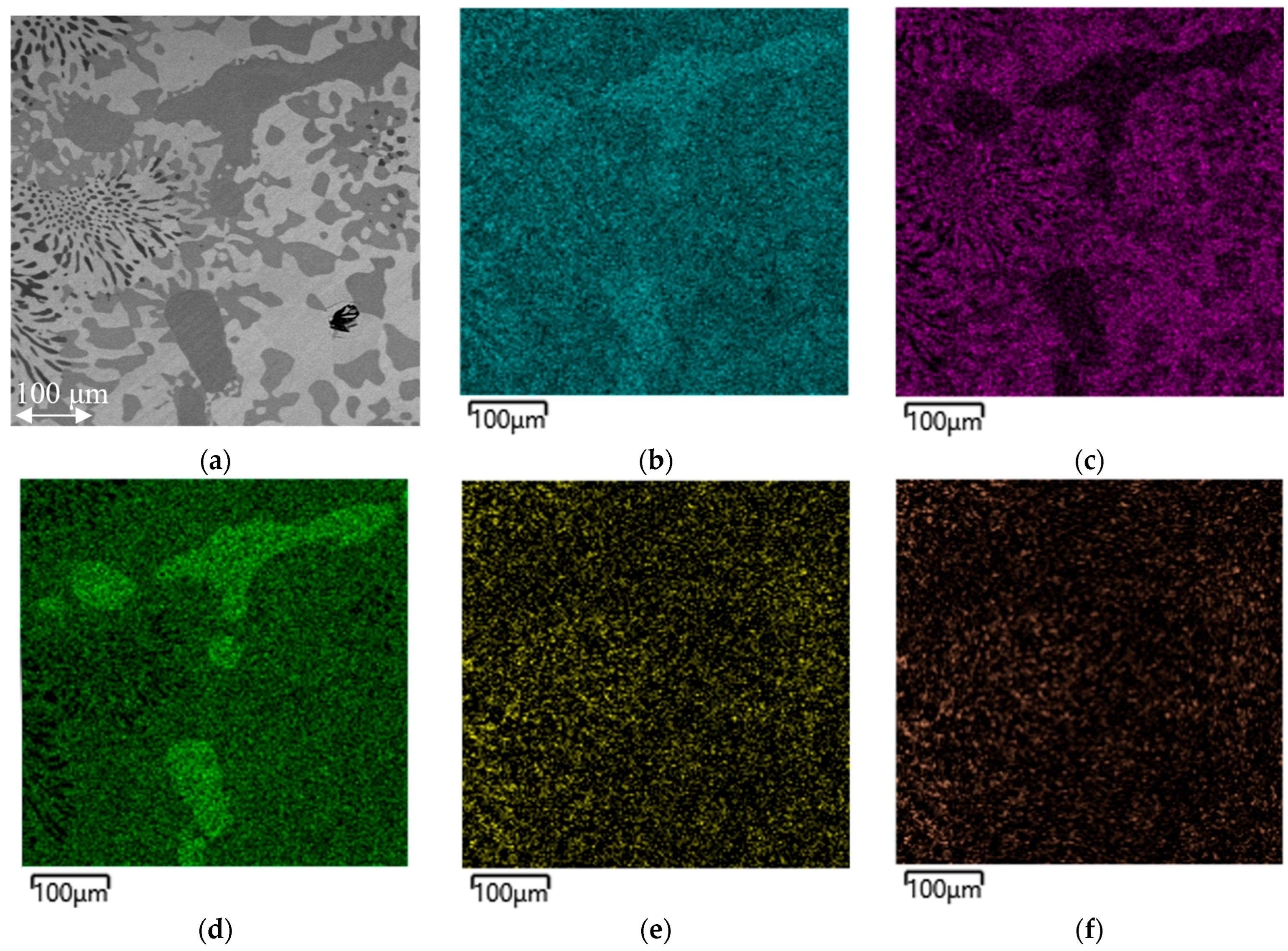
Figure 4 shows a map of the distribution of the elements in a metal sample obtained from batch 2.
The distribution maps of the elements for batches 1 and 3 are not shown, since they are similar in their distribution patterns, which is also confirmed by the compositions considered earlier (
Table 4).
Saturation with N and the formation of Cr and V nitrides at high temperatures are thermodynamically possible, but their stability decreases with increasing temperature. High temperatures above 1650 °C can be achieved due to exothermic reduction reactions [
22], which can result in local overheating with subsequent sharp cooling, which prevents the decomposition of N.
In [
23], it was experimentally shown that the solubility of N in a liquid Fe–Cr alloy increases with increasing Cr content, which explains the higher N capacity of the phase in the dark areas. Accordingly, N is concentrated in the Cr regions of the melt and a nitride phase is released upon cooling. The presence of V in the system also promotes nitride formation: the reaction 2V + N2 can occur at significantly lower temperatures (1200 °C in a nitrogen environment) [
24] than those of melting conditions (1650 °C), as a result of which V actively binds to nitrogen, forming a solid solution of (Cr, V)N.
Atmospheric N was the source of the N entering the melt. In traditional steel and ferroalloy smelting processes, the phenomenon of nitrogen absorption by the melt upon contact with the air was known. For example, when liquid FeCr was blown with air for decarburization, a noticeable enrichment of the alloy with N was observed [
25], and nitrided low-carbon FeCr with a content of 4.5–6% was also obtained by sintering crushed FeCr in air in the presence of air at 1100 °C for 6 h [
26].
Figure 5 shows a similar element distribution map of a metal sample obtained from batch 4.
From
Figure 5, it is evident that Cr is distributed over the entire surface of the sample, but is concentrated to a greater extent in the dark areas together with Si and N. V is distributed quite uniformly, mainly again bound to N, and is present to a lesser extent in the areas enriched with Si, which in turn is absent in the black phase.
Using analytical chemistry methods, the content of elements that were difficult to determine using EDS was measured. On average, the contents were as follows: C ≤ 0.10%; S ≤ 0.02%; and P ≤ 0.03%. Thus, all the studied metal samples were characterized by a low content of the listed elements. The N content was investigated by the titrimetric method (according to the GOST 21600.18-83 standard [
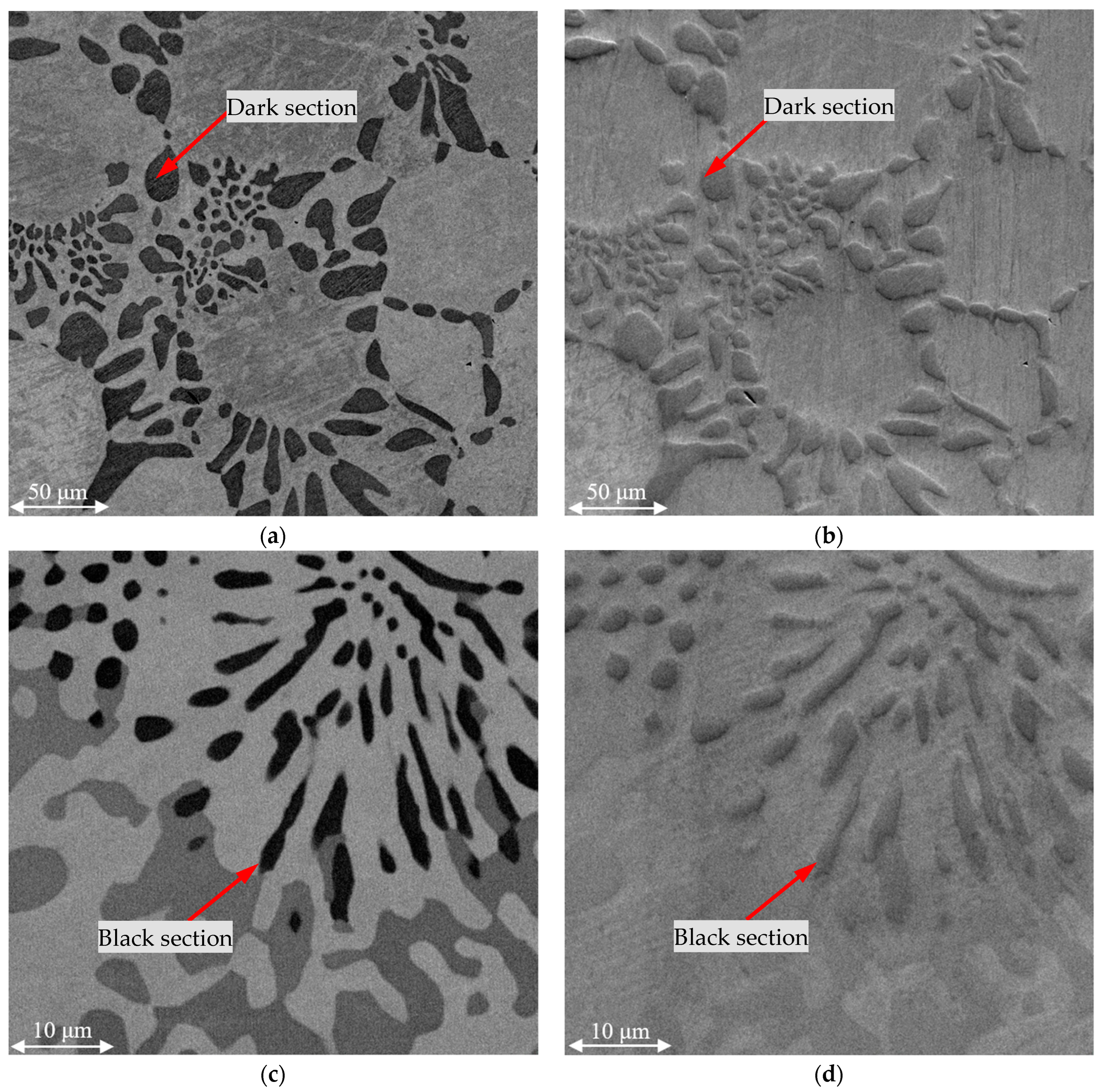
27]), which confirmed a nitrogen content of 2.6, 3.6, 2.6, and 2.1, on average, for the metal samples from batches 1, 2, 3, and 4, respectively. The metal samples were also investigated by obtaining SEM images in the secondary electron detection mode. The results are presented in
Figure 6.
As can be seen from
Figure 6, the nitrogen-containing components of the microstructure—the nitride phases—are less well ground, as can be judged by the relief shown in the images obtained using the secondary electron detection mode. This is due to the known high hardness of nitrides. Such indirect confirmation is convincing evidence of the formation of (Cr,V)N phases.
Figure 7 shows the XRD pattern of the metal obtained from batch 3, which represents the typical phase composition of the metals produced from batches 1 to 3.
The presented results indicate that the XRD analysis confirms that the metal consists of a BCC solid solution and a nitride phase Cr2N. The presence of vanadium in the nitride region, as revealed by the EDS analysis, suggests that vanadium is dissolved in the Cr2N lattice.
3.2. Slag Study
A rock-like slag was formed, which is quite strong and hard, retains its shape well, and does not disintegrate during storage for more than 15 days. This simplifies its storage and transportation, and potentially makes it promising for use as a raw material in construction. However, it should be noted that long-term durability testing is still ongoing, and further monitoring of the slag samples is being conducted to assess their stability over extended storage periods.
Table 5 shows the average chemical composition of the slags obtained with the different batches. The chemical composition of the slag samples was determined using standard analytical chemistry methods.
It is evident from the table that batches 1 and 2 resulted in the transition of the unreduced portion of Cr2O3 into the slag (4.5–6.5%). The comparatively low Cr2O3 reduction values were due to the fact that during smelting, the charge components actively interacted with the oxygen in the air, which reduced the efficiency of the reducing agents. In batch 3, this value dropped sharply to 0.9%. The slag from batch 4 of the charge components had a noticeably lower SiO2 content, which was consistent with the high Si content in the metal. Moreover, a higher MgO content was observed, which was due to the reduced portion of Cr2O3 and SiO2, as well as the slag contamination that occurred as a result of the crucible destruction and interaction with the MgO backfill. In all the samples, the portion of Al2O3 in the slag could have been overestimated due to the crucible’s dissolution, as evidenced by the slag sticking to the crucible walls, which in turn indicates wetting of the Al2O3 by the slag. That is, in the places where the slag came into contact with the crucible, the Al2O3 could have been destroyed as a result of the chemical interaction and thermal shock due to local heating, the source of which was exothermic reduction reactions. Then, the slag interacted with the MgO backfill.
Additionally, the degree of Cr extraction could have been affected by the proportion of lime: its relatively lower content in batches 1 and 2 worsened the conditions for the dissolution of Cr spinelide and the reduction of Cr, while an excess could lead to an increase in slag viscosity [
28,
29].
The slag basicity was 0.63, 0.67, 0.63, and 1.06 for batches 1, 2, 3, and 4, respectively. The data indicate an average value of 0.63–0.67; the elevated value for batch 4 may have resulted from MgO contamination originating from the backfill. The average value corresponds to acid slags and, according to the literature data, it is relatively low compared to the more common values for LC FeCr of 0.8–1.4, and closer to the values of high-carbon FeCr (~0.5) [
30,
31,
32].
Also, according to the literature data [
28,
29,
30,
31,
32,
33,
34], a higher slag basicity helps to extract chromium into the metal to a greater extent, which is consistent with the results of the smelting with batch 4 of the charge components, with the highest basicity of 1.06 (even taking into account the overestimated indicator). Nevertheless, the use of FeAlSiCa and FeSiCr ensured the formation of slag with a relatively low Cr
2O
3 content of up to 0.9% for batch 3, and a fairly typical Cr
2O
3 content of 4.5–6.5% for the LC FeCr slags for batches 2 and 1, even at very low basicity values of 0.63–0.67, which reflects the higher reducing capacity of the used reducing agents in comparison with traditional ones, and a lower dependence on the slag basicity.
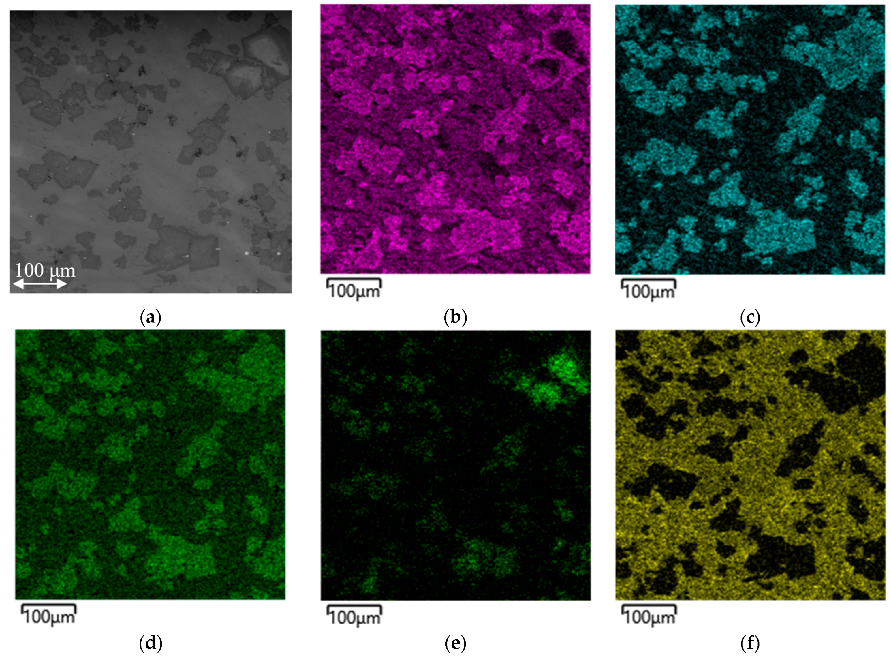
Figure 8 shows the results of the study using SEM and EDS, with the compilation of a map of the distribution of the elements on the slag sample obtained as a result of melting the charge components of batch 2.
Figure 8 shows the results of the study of the slag obtained from batch 2 as typical, and for batches 1, 3, and 4, the only difference is that for batches 3 and 4 chromium is practically absent from the element distribution maps.
A clear distribution indicates the formation of the following main phases: Mg(Cr, Al)2O4 and MgAl2O4 for the slag samples from batches 1 and 2; MgAl2O4 for batches 3 and 4; and calcium silicates are present in all the samples. Particles of reduced iron remaining in the slag and carbon particles in the slag pores are visible, the source of which was the carbon-containing conductive resin into which the studied samples were pressed for further grinding.
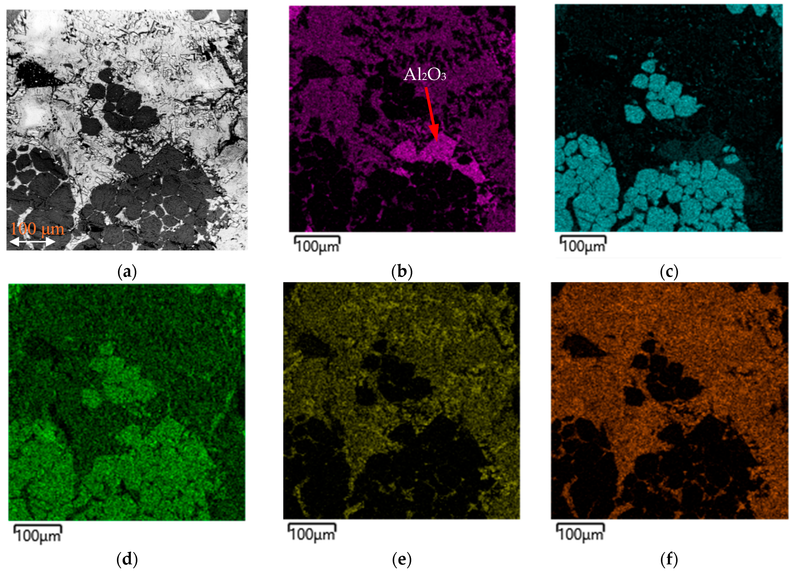
Figure 9 shows the SEM image and the element distribution map for the slag sample obtained from batch 4.
The distribution map of the elements shown in
Figure 9 confirms the typical distribution of the slag elements by phases, with the only difference being that a separate Al
2O
3 phase is visible in the observed area (
Figure 9b). The presence of this phase confirms the transition of the oxide from the crucible’s composition, associated with its partial destruction and the entry of its particles into the slag.
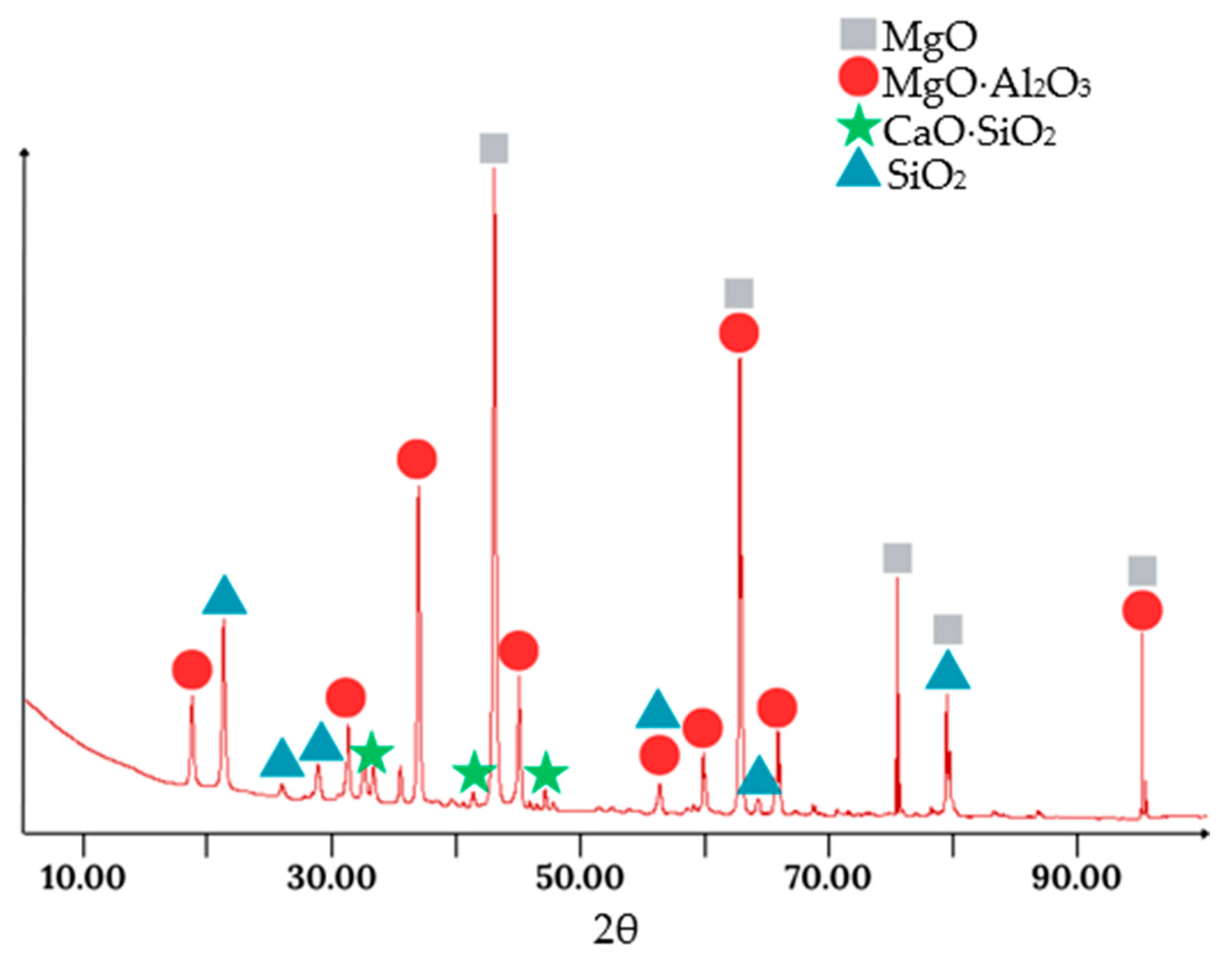
Figure 10 shows the XRD pattern of the slag obtained from batch 3.
As seen from the XRD results, the predicted phases based on the EDS analysis are largely confirmed. The significant presence of a MgO phase is also observed, indicating the considerable mixing of the slag with the MgO filler material.
4. Discussion
Figure 11 shows a graph of the changes in the content of Cr and Fe in the metal and Cr
2O
3 in the slag for the different batches.
Figure 11 clearly shows the dynamics of the changes in the degree of Cr
2O
3 reduction with an increase in the amount of reducing agents. The calculation of the Cr extraction into the metal (taking into account the Cr
2O
3 from the concentrate and the Cr from the FeSiCr dust) was 72.0, 75.7, 86.0, and 89.7% for batches 1, 2, 3, and 4, respectively. It should be noted that these figures are quite high and probably somewhat overstated, due to some error in the methods for determining the content of the elements, and the introduction of Al
2O
3 as a result of the interaction with the crucible and MgO as a result of the interaction with the backfill around the crucible. Despite the increase in the degree of Cr extraction into the metal, its content somewhat decreased, which was associated first with an increase in the Fe (batch 3) and then Si (batch 4) extraction. This was due to the increase in the amount of reducing agents introduced by the Fe and Si.
These results further support the core hypothesis that the waste-derived FeAlSiCa alloy is an effective reductant for chromium oxide. They correspond to a high Cr recovery of approximately 86–90% into the metal phase, significantly higher than the typical values reported for conventional metallothermic processes (e.g., ~76–79% in aluminothermic reduction [
30,
31]). Such efficient extraction is attributed to the highly reactive elements in FeAlSiCr—namely Ca, Al, and Si—which exhibit a much stronger affinity for O
2 than C does. The slight 10% excess of FeAlSiCa was ideal; a further increase to 20% excess led to over-reduction, resulting in chromium silicide formation, and causing the formation of chromium silicide phases in the alloy. This observation aligns with the behavior of traditional silicothermic processes, where an overabundance of silicon leads to higher Si pick-up in the FeCr product [
20].
While high chromium recovery was achieved with batch 3, the process had certain limitations. At excess reductant levels (batch 4), silicon-rich phases, such as chromium silicides, formed, reducing the Cr content in the alloy. Additionally, the presence of nitrogen in the air contributed to nitride formation, which may be undesirable in some alloy applications. Minor iron losses were also observed, particularly in the form of residual Fe oxides in the slag. Control over the atmosphere, slag composition, and reductant dosing is therefore critical for optimizing both Cr and Fe recovery.
Carbothermic reactions are endothermic and rely on a continuous energy input, as well as an excess of carbon to drive the equilibrium and generate sufficient CO gas to facilitate the reduction. This results in substantial greenhouse gas emissions—it was estimated that in 2016, roughly 15.5 million tons of CO
2 were emitted globally from fossil C usage in FeCr production [
20]. By contrast, metallothermic reduction with FeAlSiCa completely eliminates the direct use of C, thereby avoiding the significant CO and CO
2 emissions inherent in coke-based smelting. Any CO
2 emissions associated with FeAlSiCa occur upstream (e.g., during its preparation from waste coal and slag), and at the smelting stage the process is virtually carbon-free, directly addressing the need to decarbonize ferroalloy production. The in situ chemical reactions in the FeAlSiCa process are exothermic (analogous to a thermite reaction), which means the reduction releases heat instead of consuming it. This exothermicity can significantly reduce the external energy requirement. Thermochemical simulations and experiments by other researchers have confirmed that using silicon or aluminum as reductants can lower the specific electrical energy consumption compared to a purely carbothermic operation [
20].
The use of FeSiCr dust in the charge components further contributed chromium units and silicon, slightly boosting the chromium yield while disposing of a dust that otherwise poses handling and environmental challenges.
Another important outcome of using the FeAlSiCa reductant was the favorable characteristics of the resulting slag. In all the experimental batches, the slag was observed to be dense, stone-like, and volumetrically stable, showing no signs of self-disintegration or dusting even after weeks of exposure to air. This is in contrast to certain slags from conventional processes that can crumble or form a fine powder upon cooling and weathering (for example, some FeCr slags with high CaO can undergo phase transformations that cause disintegration). The minor amount of Cr remaining was largely locked in the spinel structure, which is a chemically stable form (spinel-embedded chromium is less leachable and less prone to oxidation into hazardous Cr6+).
Moreover, the slag’s mineralogy (rich in alumina, magnesia, and silicate phases) makes it a viable candidate for reuse in various applications. It could potentially serve as a construction aggregate, road ballast, or as feedstock for cement clinker production, similar to how blast furnace slag is used, provided any residual chromium is appropriately stabilized.
The FeCr samples obtained from batches 1, 2, and 3 meet the requirements for FeCr60C1N3 grade (low-carbon nitrogen-containing FeCr) according to ISO 5448-81 [
35]. This makes the obtained metal samples suitable for alloying nitrogen-containing stainless steels. The metal obtained from batch 4 is close to the requirement for FeCr60C50Si7LP (high-carbon FeCr) according to ISO 5448-81 [
35], but with a low C content and increased N; it can also be considered a low-carbon nitrogen-containing FeCr with an increased Si content. The metal samples also meet the listed requirements for LC FeCr grades in terms of their C, S, and P contents.
Four different batches were tested by adjusting the amount of the reducing agents (FeAlSiCa and FeSiCr) relative to the stoichiometric requirement. Batch 1 used a 10% deficiency of the reductants and showed the lowest chromium recovery, with a high Cr2O3 content in the slag (6.5%) and a Cr–Fe–N alloy containing ~64% Cr and 2.6% N. Batch 2, with a stoichiometric amount of the reducing agents, yielded slightly improved results, including a higher nitrogen content (3.6%) and a moderate reduction in the slag’s Cr2O3. Batch 3, with a 10% excess of the reducing agents, was optimal—achieving a nearly complete reduction of Cr2O3 (down to 0.9% in the slag), and a high chromium recovery of ~86%, with the resulting metal consisting of a BCC solid solution and Cr–V nitride phases. Batch 4, with a 20% excess, led to the formation of chromium silicides (Cr3Si, Cr5Si3), a decrease in the chromium content in the alloy, and further reduction in the Cr2O3 in the slag. Overall, batch 3 demonstrated the best balance of chromium yield, phase composition, and minimal slag losses.
The reduction process proceeds through thermodynamically favorable reactions between Cr2O3 and the active components of the FeAlSiCa alloy, namely Ca, Al, and Si. These reactions are exothermic and drive the transformation of Cr2O3 into metallic chromium, which forms a solid solution with Fe. Nitrogen from the air dissolves in the melt, forming Cr-V nitrides, while excess Si at higher reductant levels promotes the formation of chromium silicides. The slag primarily consists of MgAl2O4 spinel and CaO-SiO2-Al2O3 phases, stabilizing it physically and chemically.
Having demonstrated the effectiveness of FeAlSiCa in laboratory-scale smelting tests, the next step is to translate this into an industrial context. A logical avenue for scale-up is the use of an electric arc furnace for the larger-scale metallothermic smelting of chromite.
5. Conclusions
This article proves the prospects of using FeAlSiCa and FeSiCr dust as reducing agents for smelting LC FeCr, which helps to improve the stability of the technology, reduce its carbon footprint, and reduce its cost. Four batches, with the introduction of a mixture of reducing agents in a 1-to-1 ratio, were considered as follows: (1) a 10% deficiency; (2) a stoichiometric amount; (3) a 10% excess; and (4) a 20% excess.
The research found that the use of FeAlSiCa and FeSiCr dust allows for the obtainment of LC FeCr containing 2.6–3.6% N in nitride phases (batches 1, 2, and 3), or low-carbon nitrogen-containing (2.1%) FeCr with a high silicon content of 8.2% (batch 4). This feature was because the excess of Si-containing reducing agents led to the formation of silicides. Considering that in batches 3 and 4, there was an increased Cr extraction of 75.7 and 86.0% (with a Cr2O3 residue in the slag of 0.4–0.9%), and compliance with the requirements for LC FeCr grades for all the elements, batch 3 was optimal.
The resulting slag from all the batches was stone-like, sufficiently strong and hard, and did not undergo self-disintegration when stored in the air for more than 15 days. The slag basicity of 0.63–0.67, judging by the research results, had a lesser effect on the degree of Cr extraction into the alloy compared to traditional technologies, which confirms the high reducing capacity of FeAlSiCa and FeSiCr dust.
The alloys studied in this work, being cost-effective products, showed high efficiency as reducing agents for obtaining FeCr from Cr concentrate. Further research will aim to investigate their effectiveness under inert or vacuum conditions, as well as in an electric arc furnace typically used for ferroalloy smelting.
