
A Study on the Removal of Heat Generated by a Lithium-Ion Battery Module: A Fan-Assisted Battery Cooling Approach


Abstract
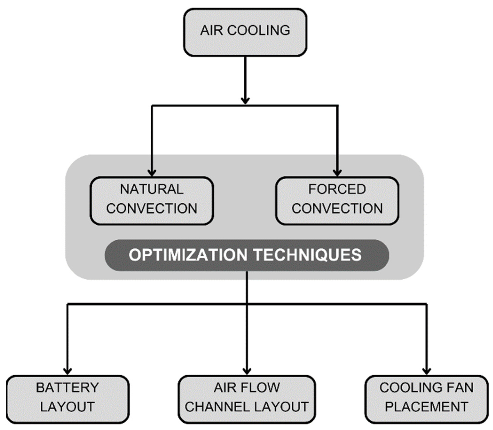
1. Introduction
2. Materials and Methods
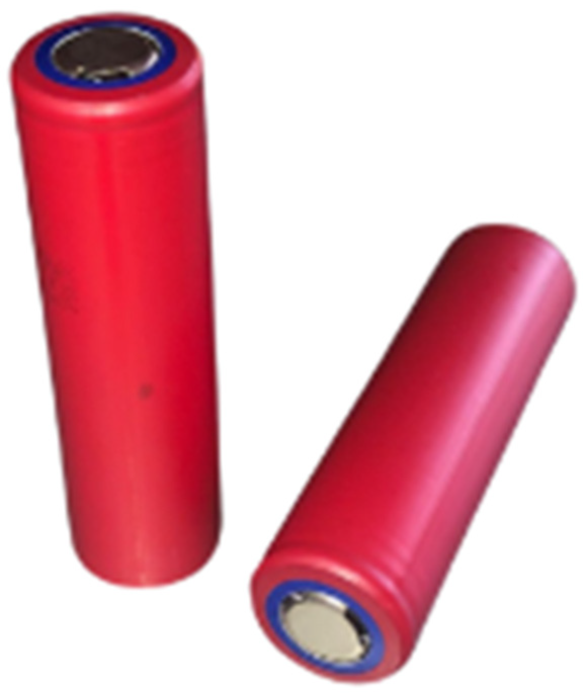
2.1. LiB Cell and Module
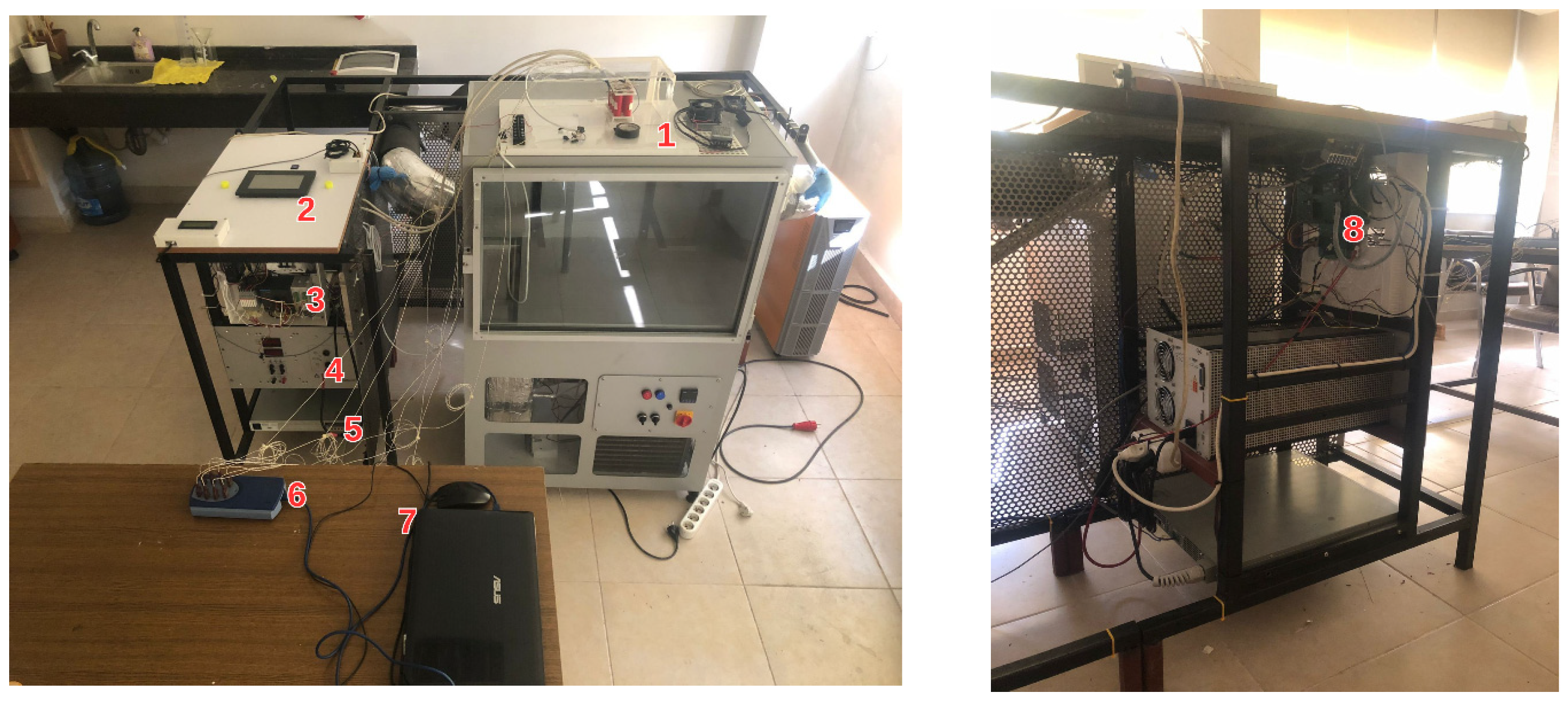
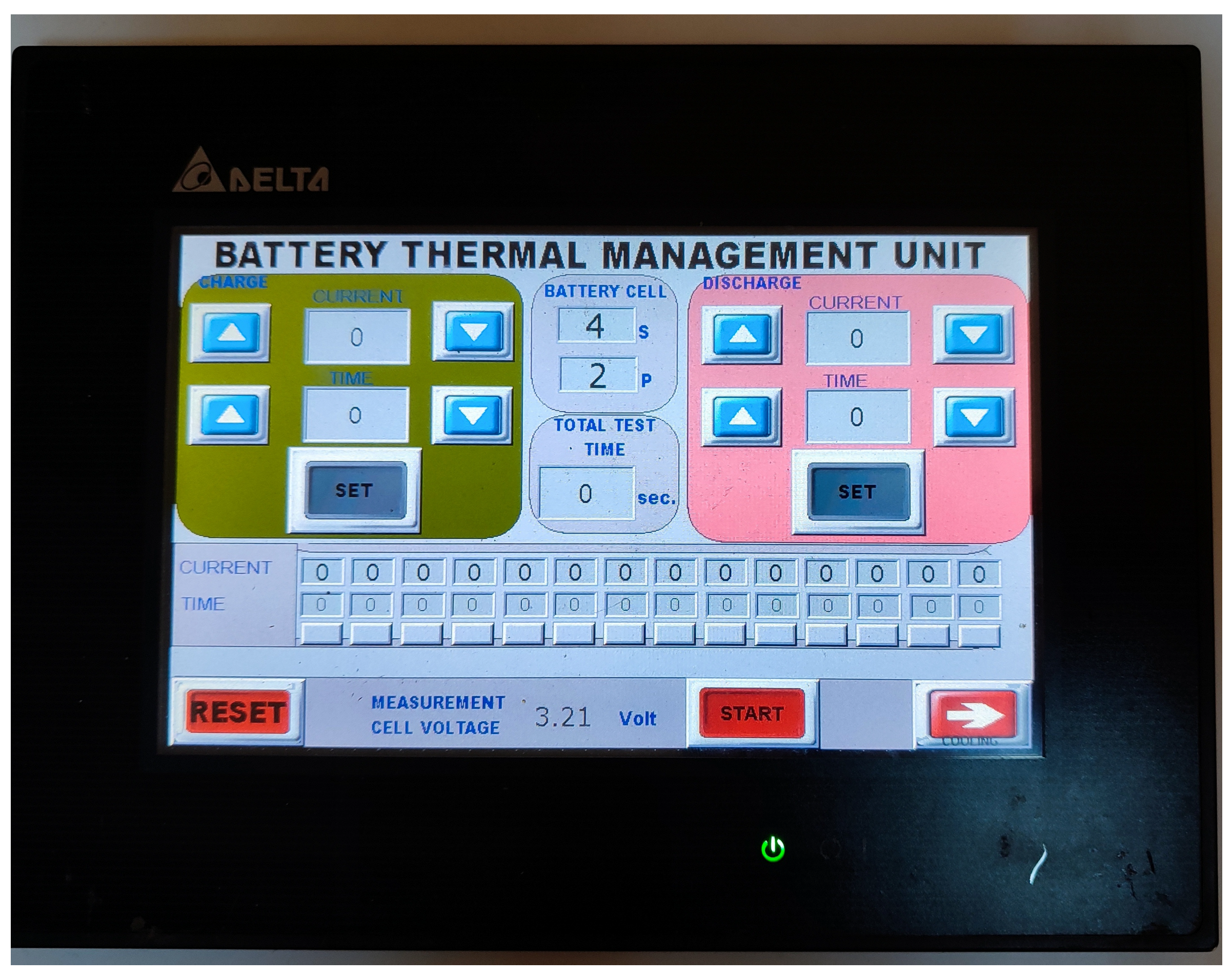
2.2. Test Bench
2.3. Experimental Studies
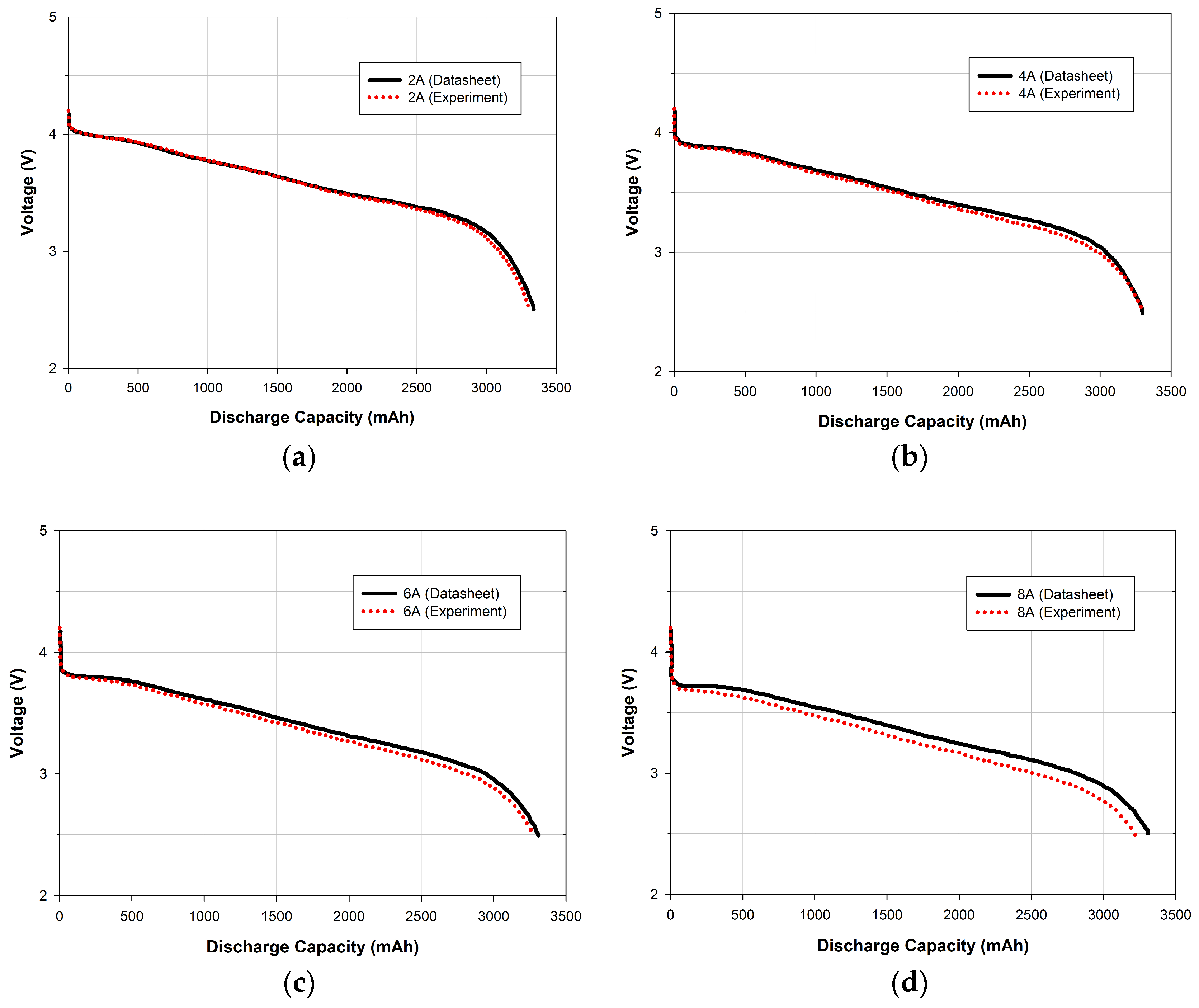
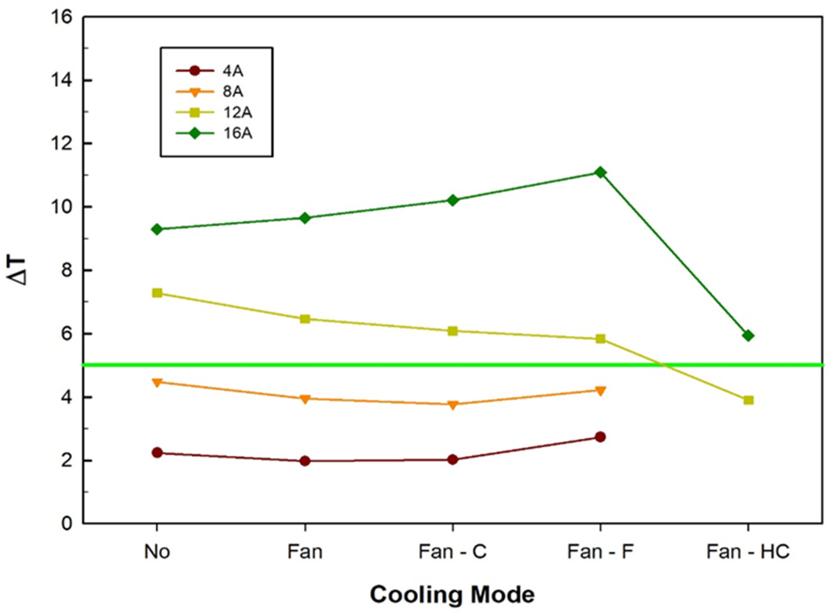
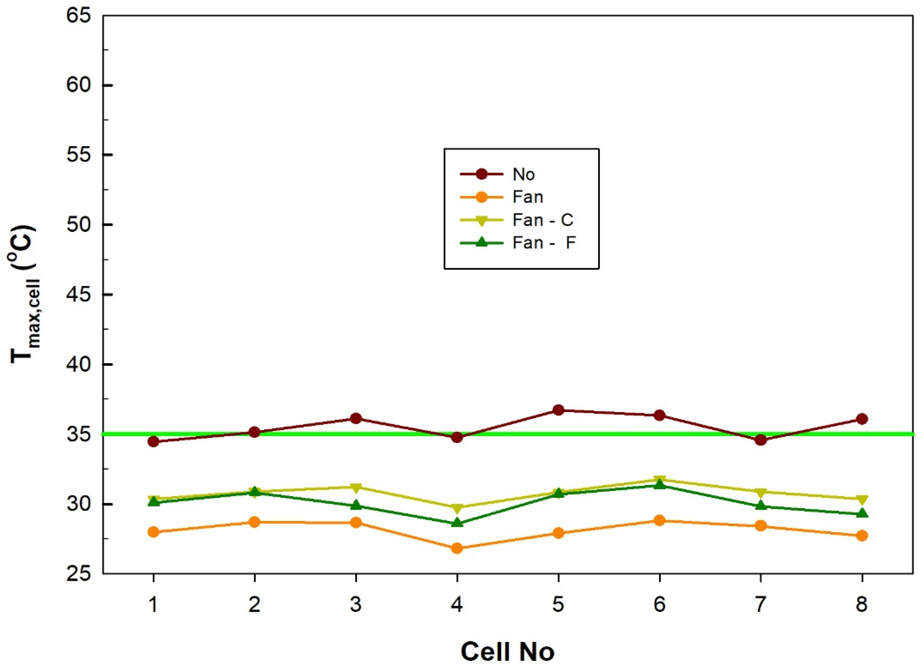
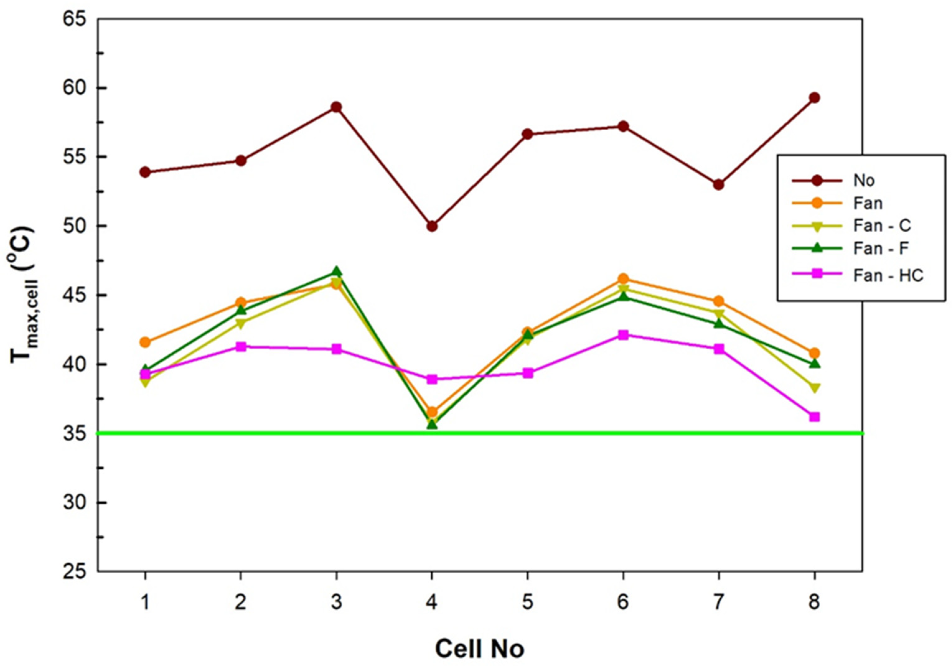
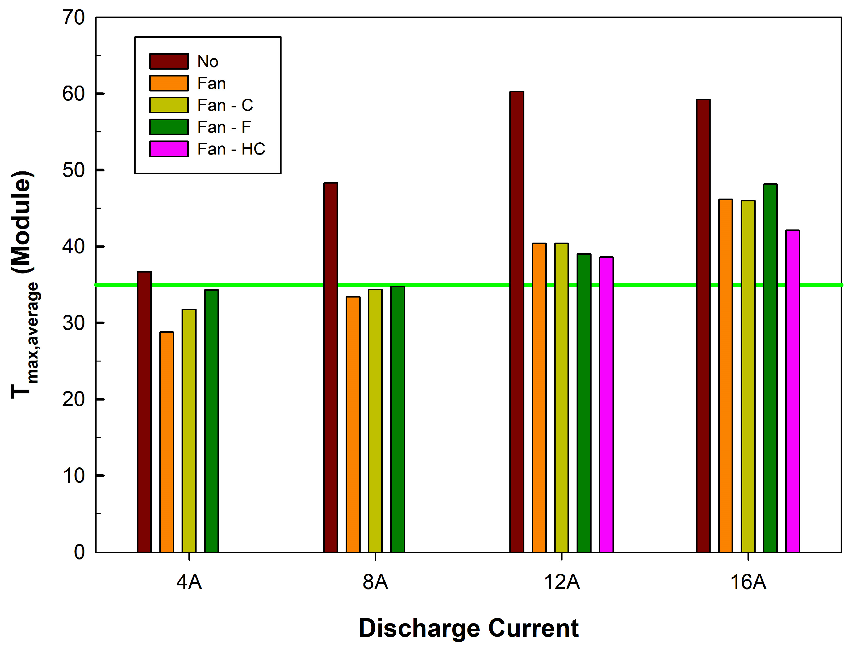
3. Results and Discussion
4. Conclusions
Author Contributions
Funding
Data Availability Statement
Conflicts of Interest
Abbreviations
| BMS | Battery management system |
| BTMS | Battery thermal management system |
| C | Coarse |
| ERB | Epoxy resin board |
| EV | Electric vehicle |
| F | Fine |
| HC | Honeycomb |
| LiB | Lithium-ion battery |
| PCM | Phase change material |
| PLC | Programmable logic controller |
| SEI | Solid electrolyte interphase |
| T | Temperature |
| Tmax | Maximum temperature |
| ΔT | Temperature difference |
References
- Zhao, R.; Liu, J.; Gu, J.; Zhai, L.; Ma, F. Experimental Study of a Direct Evaporative Cooling Approach for Li-Ion Battery Thermal Management. Int. J. Energy Res. 2020, 44, 6660–6673. [Google Scholar] [CrossRef]
- Anamtawach, C.; Odngam, S.; Sumpavakup, C. Experimental Investigation on Affecting Air Flow against the Maximum Temperature Difference of a Lithium-Ion Battery with Heat Pipe Cooling. World Electr. Veh. J. 2023, 14, 306. [Google Scholar] [CrossRef]
- Wang, T.; Tseng, K.J.; Zhao, J. Development of Efficient Air-Cooling Strategies for Lithium-Ion Battery Module Based on Empirical Heat Source Model. Appl. Therm. Eng. 2015, 90, 521–529. [Google Scholar] [CrossRef]
- Xu, L.; Wang, S.; Xi, L.; Li, Y.; Gao, J. A Review of Thermal Management and Heat Transfer of Lithium-Ion Batteries. Energies 2024, 17, 3873. [Google Scholar] [CrossRef]
- Singh, L.K.; Kumar, R.; Gupta, A.K.; Sharma, A.K.; Panchal, S. Computational Study on Hybrid Air-PCM Cooling inside Lithium-Ion Battery Packs with Varying Number of Cells. J. Energy Storage 2023, 67, 107649. [Google Scholar] [CrossRef]
- Bibin, C.; Vijayaram, M.; Suriya, V.; Sai Ganesh, R.; Soundarraj, S. A Review on Thermal Issues in Li-Ion Battery and Recent Advancements in Battery Thermal Management System. Mater. Today Proc. 2020, 33, 116–128. [Google Scholar] [CrossRef]
- Wang, J.; Huang, W.; Pei, A.; Li, Y.; Shi, F.; Yu, X.; Cui, Y. Improving Cyclability of Li Metal Batteries at Elevated Temperatures and Its Origin Revealed by Cryo-Electron Microscopy. Nat. Energy 2019, 4, 664–670. [Google Scholar] [CrossRef]
- Vikram, S.; Vashisht, S.; Rakshit, D.; Wan, M.P. Recent Advancements and Performance Implications of Hybrid Battery Thermal Management Systems for Electric Vehicles. J. Energy Storage 2024, 90, 111814. [Google Scholar] [CrossRef]
- Illner, M.; Thüsing, K.; Salles, A.; Trettenhann, A.; Albrecht, S.; Winkler, M. Switchable Heat Pipes for Eco-Friendly Battery Cooling in Electric Vehicles: A Life Cycle Assessment. Energies 2024, 17, 938. [Google Scholar] [CrossRef]
- Fu, P.; Zhao, L.; Wang, X.; Sun, J.; Xin, Z. A Review of Cooling Technologies in Lithium-Ion Power Battery Thermal Management Systems for New Energy Vehicles. Processes 2023, 11, 3450. [Google Scholar] [CrossRef]
- Li, W.; Wang, X.; Cen, P.Y.; Chen, Q.; De Cachinho Cordeiro, I.M.; Kong, L.; Lin, P.; Li, A. A Comparative Numerical Study of Lithium-Ion Batteries with Air-Cooling Systems towards Thermal Safety. Fire 2024, 7, 29. [Google Scholar] [CrossRef]
- Hakeem, A.A.A.; Solyali, D. Empirical Thermal Performance Investigation of a Compact Lithium Ion Battery Module under Forced Convection Cooling. Appl. Sci. 2020, 10, 3732. [Google Scholar] [CrossRef]
- Fan, Y.; Bao, Y.; Ling, C.; Chu, Y.; Tan, X.; Yang, S. Experimental Study on the Thermal Management Performance of Air Cooling for High Energy Density Cylindrical Lithium-Ion Batteries. Appl. Therm. Eng. 2019, 155, 96–109. [Google Scholar] [CrossRef]
- Zhao, G.; Wang, X.; Negnevitsky, M.; Zhang, H.; Li, C. Performance Improvement of a Novel Trapezoid Air-Cooling Battery Thermal Management System for Electric Vehicles. Sustainability 2022, 14, 4975. [Google Scholar] [CrossRef]
- Wang, M.; Teng, S.; Xi, H.; Li, Y. Cooling Performance Optimization of Air-Cooled Battery Thermal Management System. Appl. Therm. Eng. 2021, 195, 117242. [Google Scholar] [CrossRef]
- Zhang, S.B.; He, X.; Long, N.C.; Shen, Y.J.; Gao, Q. Improving the Air-Cooling Performance for Lithium-Ion Battery Packs by Changing the Air Flow Pattern. Appl. Therm. Eng. 2023, 221, 119825. [Google Scholar] [CrossRef]
- E, J.; Zeng, Y.; Jin, Y.; Zhang, B.; Huang, Z.; Wei, K.; Chen, J.; Zhu, H.; Deng, Y. Heat Dissipation Investigation of the Power Lithium-Ion Battery Module Based on Orthogonal Experiment Design and Fuzzy Grey Relation Analysis. Energy 2020, 211, 118596. [Google Scholar] [CrossRef]
- Kim, C.; Han, J.; Hong, S. Evaluation of Spoiler Model Based on Air Cooling on Lithium-Ion Battery Pack Temperature Uniformity. Processes 2022, 10, 505. [Google Scholar] [CrossRef]
- Bisht, A.S.; Bisht, V.S.; Bhandari, P.; Rawat, K.S.; Alam, T.; Blecich, P. The Use of a Vortex Generator for the Efficient Cooling of Lithium-Ion Batteries in Hybrid Electric Vehicles. Processes 2023, 11, 500. [Google Scholar] [CrossRef]
- Gao, Y.; Ji, W.; Chen, X. Numerical Study on Thermal Management of Air-Cooling Model for Diamond, Triangular and Rectangular Lithium-Ion Batteries of Electric Vehicles. Processes 2022, 10, 1104. [Google Scholar] [CrossRef]
- Lin, D.; Peng, P.; Wang, Y.; Qiu, Y.; Wu, W.; Jiang, F. Numerical Investigation of the Thermal Performance of Air-Cooling System for a Lithium-Ion Battery Module Combined with Epoxy Resin Boards. Batteries 2024, 10, 318. [Google Scholar] [CrossRef]
- Jeon, D.H.; Baek, S.M. Thermal Modeling of Cylindrical Lithium Ion Battery during Discharge Cycle. Energy Convers. Manag. 2011, 52, 2973–2981. [Google Scholar] [CrossRef]
- Kirad, K.; Chaudhari, M. Design of Cell Spacing in Lithium-Ion Battery Module for Improvement in Cooling Performance of the Battery Thermal Management System. J. Power Sources 2021, 481, 229016. [Google Scholar] [CrossRef]
- Ghorbanian, K.; Soltani, M.R.; Manshadi, M.D. Experimental Investigation on Turbulence Intensity Reduction in Subsonic Wind Tunnels. Aerosp. Sci. Technol. 2011, 15, 137–147. [Google Scholar] [CrossRef]
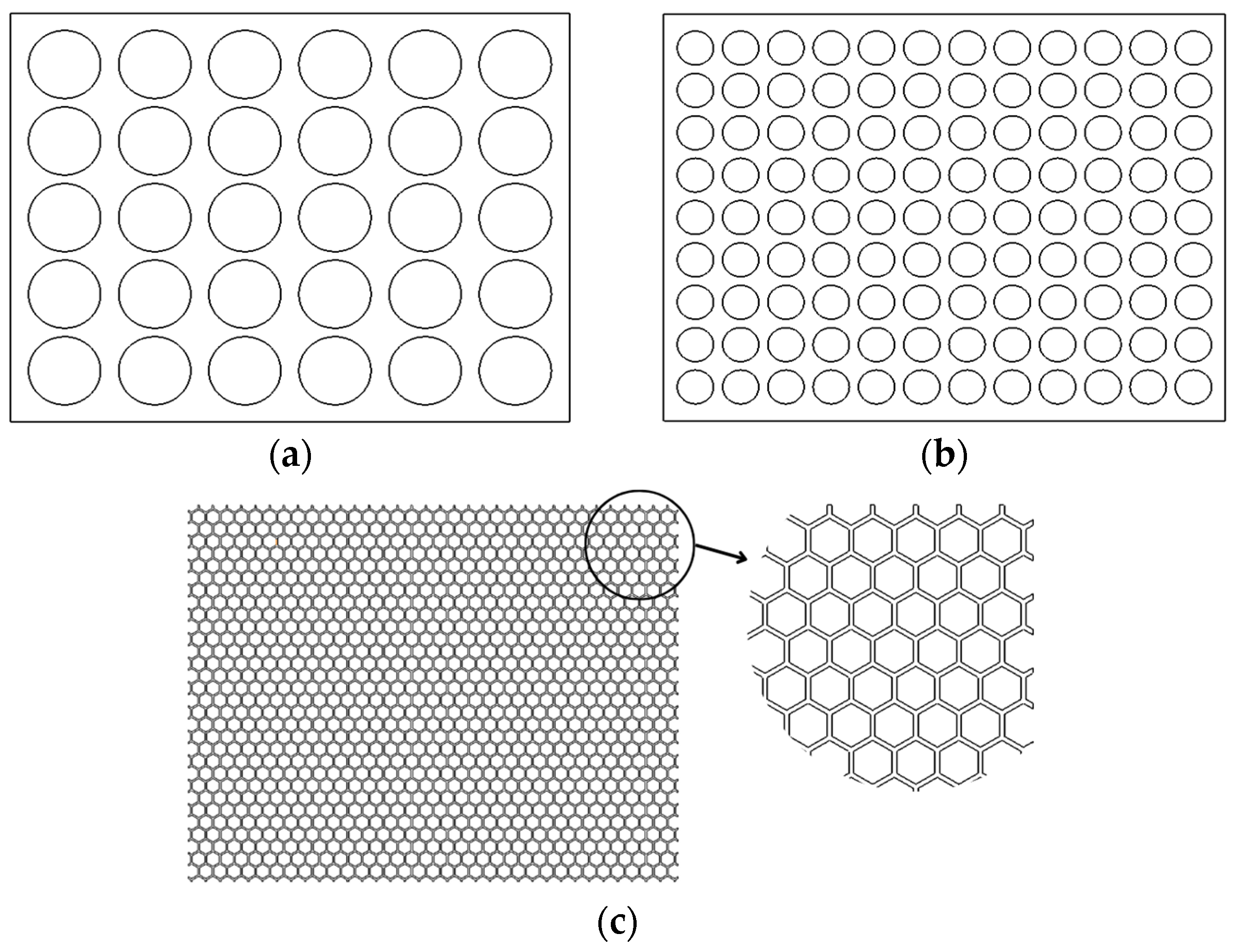
- Rahmani, A.; Dibaj, M.; Akrami, M. Enhancing Heat Storage Cooling Systems via the Implementation of Honeycomb-Inspired Design: Investigating Efficiency and Performance. Energies 2024, 17, 351. [Google Scholar] [CrossRef]
- Motloch, C.G.; Christophersen, J.P.; Belt, J.R.; Wright, R.B.; Hunt, G.L.; Sutula, R.A.; Duong, T.; Tartamella, T.J.; Haskins, H.J.; Miller, T.J. High-Power Battery Testing Procedures and Analytical Methodologies for HEV’s. SAE Trans. 2002, 111, 797–802. [Google Scholar]
- Ahmadian-Elmi, M.; Zhao, P. Review of Thermal Management Strategies for Cylindrical Lithium-Ion Battery Packs. Batteries 2024, 10, 50. [Google Scholar] [CrossRef]
- Rahmani, A.; Dibaj, M.; Akrami, M. Recent Advancements in Battery Thermal Management Systems for Enhanced Performance of Li-Ion Batteries: A Comprehensive Review. Batteries 2024, 10, 265. [Google Scholar] [CrossRef]
- Wang, Q.; Ping, P.; Zhao, X.; Chu, G.; Sun, J.; Chen, C. Thermal Runaway Caused Fire and Explosion of Lithium Ion Battery. J. Power Sources 2012, 208, 210–224. [Google Scholar] [CrossRef]
- Zhang, Y.; Song, X.; Ma, C.; Hao, D.; Chen, Y. Effects of the Structure Arrangement and Spacing on the Thermal Characteristics of Li-Ion Battery Pack at Various Discharge Rates. Appl. Therm. Eng. 2020, 165, 114610. [Google Scholar] [CrossRef]
- Liu, H.; Wei, Z.; He, W.; Zhao, J. Thermal Issues about Li-Ion Batteries and Recent Progress in Battery Thermal Management Systems: A Review. Energy Convers. Manag. 2017, 150, 304–330. [Google Scholar] [CrossRef]
- Sahin, R.C.; Gocmen, S.; Cetkin, E. Thermal Management System for Air-Cooled Battery Packs with Flow-Disturbing Structures. J. Power Sources 2022, 551, 232214. [Google Scholar] [CrossRef]
- Rahman, T.; Alharbi, T. Exploring Lithium-Ion Battery Degradation: A Concise Review of Critical Factors, Impacts, Data-Driven Degradation Estimation Techniques, and Sustainable Directions for Energy Storage Systems. Batteries 2024, 10, 220. [Google Scholar] [CrossRef]
- Zhang, F.; Shi, Y.; He, Y.; Liu, P. Design and Optimization of an F-type Air-Cooling Structure for Lithium-Ion Battery of Electric Vehicle. Energy Technol. 2023, 11, 2300243. [Google Scholar] [CrossRef]
- Zhang, F.; Lin, A.; Wang, P.; Liu, P. Optimization Design of a Parallel Air-Cooled Battery Thermal Management System with Spoilers. Appl. Therm. Eng. 2021, 182, 116062. [Google Scholar] [CrossRef]
- Li, X.; Liu, J.; Li, X. A Y-Type Air-Cooled Battery Thermal Management System with a Short Airflow Path for Temperature Uniformity. Batteries 2024, 10, 302. [Google Scholar] [CrossRef]
- Guo, J.; Li, Y.; Pedersen, K.; Stroe, D.-I. Lithium-Ion Battery Operation, Degradation, and Aging Mechanism in Electric Vehicles: An Overview. Energies 2021, 14, 5220. [Google Scholar] [CrossRef]
- Menye, J.S.; Camara, M.-B.; Dakyo, B. Lithium Battery Degradation and Failure Mechanisms: A State-of-the-Art Review. Energies 2025, 18, 342. [Google Scholar] [CrossRef]


| Heat generation due to current flow during discharging taking place in a LiB | |
| Heat generation caused by internal resistance of the cell | |
| , , , and represent over potential, voltage through battery terminals, flowing current across battery, and battery electrical conductivity, respectively. | |
| Heat generation caused by a change in entropy due to chemical reaction | |
| , , , , and represent charge number in the reaction, temperature, entropy change, Faraday constant, and Gibbs energy change, respectively. | |
| Capacity | Minimum: 3350 mAh, Typical: 3450 mAh |
| Nominal voltage | 3.6 V |
| Energy density | Volumetric: 693 Wh/L, Gravimetric: 224 Wh/kg |
| Positive electrode | Lithium Cobalt Oxide (LiCO2) |
| Negative electrode | Graphite |
| Electrolyte | Ethylene Carbonate–Solvent (C3H4O3) Diethyl Carbonate–Solvent (C5H10O3) Lithium Hexafluorophosphate–Salt (LiPF6) |
| Weight | 48 g |
| Dimensions | Height: 65.3 mm (max.) Diameter: 18.5 mm (max.) Cap Diameter: 9 mm (max.) |
| Rated output voltage | 100 V |
| Rated output current | 15 A |
| Rated output power | 1500 W |
| Load regulation | Voltage: 12 mV, Current: 8 mA |
| Line regulation | Voltage: 12 mV, Current: 3.5 mA |
| Transient response time | 1 ms |
| Operating temperature | 0 to 50 °C |
| Input voltage | 230 V/115 V |
| Operating temperature | 0–35 °C |
| Load voltage | 1–75 VDC |
| Load current | 1–100 ADC |
| Load resistance | 0.02–10 kΩ |
| Power max. | 1500 W |
| Dimensions | 250 × 220 × 440 mm |
| Weight | 12 kg |
| Temperature range | −75 °C to 260 °C |
| Accuracy | −40 °C to 125 °C: ±0.5 °C |
| Tip construction | 125 °C to 260 °C: ±0.4 °C |
| Cable material | Exposed junction/welded tip |
| Length | Fiberglass |
| Number of channels | 8 |
| Temperature accuracy | The sum of ±0.2% and ±0.5% °C |
| Voltage accuracy | The sum of ±0.2% and ±10 μV |
| Overload protection | ±30 V |
| Voltage input | ±70 V |
| Reading rate | Up to 10 per second |
| Dimensions | 201 × 104 × 34 mm |
| Rated voltage | 24 VDC |
| Operation voltage | 14–26.4 VDC |
| Input current | 0.5 (Max. 0.75) A |
| Input power | 12 (Max. 18) W |
| Speed | 5700 rpm |
| Max. airflow | 2.270 (Min. 2.040) m3/min |
| Max. air pressure | 202.3 (Min. 163.9) Pa |
| Acoustical noise (Avg.) | 52.5 (Max. 56.5) dB-A |
| Insulation type | UL: Class A |
| 4 A | 8 A | 12 A | 16 A | |
|---|---|---|---|---|
| Cooling | Tmax (°C) | |||
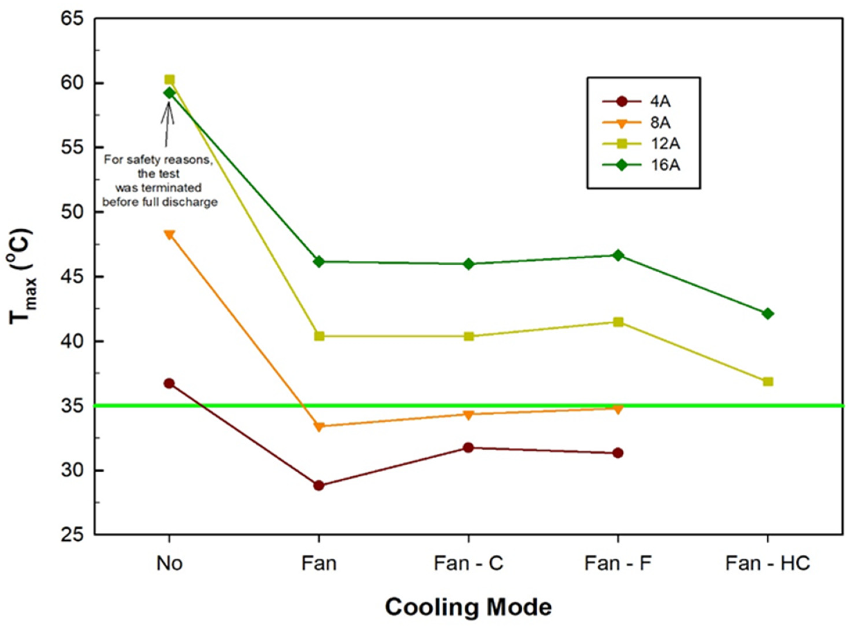
| No | 36.701 | 48.307 | 60.275 | 59.25 |
| Reduction (%) | ||||
| Fan | 21.52 | 30.82 | 32.98 | 22.1 |
| Fan–C | 13.47 | 28.9 | 33.02 | 22.39 |
| Fan–F | 14.65 | 28 | 31.17 | 21.24 |
| Fan–HC | - | - | 38.82 | 28.89 |
| Ref. | Tmax | ΔT | Comment |
|---|---|---|---|
| [34] | 5.66% | 94.26% | Adding baffles to some airflow channels and changing battery box corner |
| [35] | 6.66% | 94.24% | Adding spoilers, optimizing length and height of the spoilers and manifold |
| [36] | 3.68% | 47.2% | Using Y-type air-cooled instead T-type |
| Current Study | 28.89% | 36.05% | HC structural layout |
Disclaimer/Publisher’s Note: The statements, opinions and data contained in all publications are solely those of the individual author(s) and contributor(s) and not of MDPI and/or the editor(s). MDPI and/or the editor(s) disclaim responsibility for any injury to people or property resulting from any ideas, methods, instructions or products referred to in the content. |
© 2025 by the authors. Licensee MDPI, Basel, Switzerland. This article is an open access article distributed under the terms and conditions of the Creative Commons Attribution (CC BY) license (https://creativecommons.org/licenses/by/4.0/).
Share and Cite
Tosun, E.; Keyinci, S.; Yakaryilmaz, A.C.; Ozcanli, M. A Study on the Removal of Heat Generated by a Lithium-Ion Battery Module: A Fan-Assisted Battery Cooling Approach. Processes 2025, 13, 848. https://doi.org/10.3390/pr13030848
Tosun E, Keyinci S, Yakaryilmaz AC, Ozcanli M. A Study on the Removal of Heat Generated by a Lithium-Ion Battery Module: A Fan-Assisted Battery Cooling Approach. Processes. 2025; 13(3):848. https://doi.org/10.3390/pr13030848
Chicago/Turabian StyleTosun, Erdi, Sinan Keyinci, Ali Cem Yakaryilmaz, and Mustafa Ozcanli. 2025. "A Study on the Removal of Heat Generated by a Lithium-Ion Battery Module: A Fan-Assisted Battery Cooling Approach" Processes 13, no. 3: 848. https://doi.org/10.3390/pr13030848
APA StyleTosun, E., Keyinci, S., Yakaryilmaz, A. C., & Ozcanli, M. (2025). A Study on the Removal of Heat Generated by a Lithium-Ion Battery Module: A Fan-Assisted Battery Cooling Approach. Processes, 13(3), 848. https://doi.org/10.3390/pr13030848