Abstract
With the progressive depletion of coal resources, the recovery of shaft pillars has become an important means of improving resource utilization and reducing waste. Taking the main shaft pillar recovery of the Longxiang Coal Mine at the stage of mine closure as the engineering background, this study systematically investigates ground subsidence prediction and shaft stability control under strip mining with symmetrical extraction. An improved subsidence prediction model was established by integrating the probability integral method with superposition theory, and its validity was verified through numerical simulations and field monitoring data. The results demonstrate that the proposed method can accurately capture the subsidence behavior under complex geological conditions, with prediction errors ranging from 6.4 mm to 399.1 mm. In fully subsided zones, the percentage error was as low as 1.1–3.5%, while larger deviations were observed in areas where subsidence was incomplete, confirming both the reliability and the practical limitations of the method under different conditions. Furthermore, the deformation mechanisms of the shaft during pillar recovery were analyzed. Monitoring results indicated that the maximum subsidence at the east and west sides of the shaft reached 7620.6 mm, accompanied by local cracks exceeding 1500 mm, which caused significant damage to surface structures. To address these risks, a safety control scheme based on an integrated “prediction–monitoring–control” framework is proposed, including shaft wall reinforcement, optimization of mining parameters, and continuous ground subsidence monitoring. By combining real-time monitoring with the superposition of small working face predictions, the scheme enables maximum recovery of shaft pillar coal while ensuring operational safety. This study provides a scientific basis and technical support for shaft pillar recovery in Longxiang Coal Mine and offers valuable theoretical guidance for similar mine closure projects, with significant implications for engineering practice.
1. Introduction
Coal is a critical primary energy source and a strategic resource in China, playing a dominant role in the country’s energy consumption structure for many years. As high-quality shallow coal resources are gradually depleted, the extraction of deep and complex geological coal reserves has become an inevitable trend. During the mining process, a substantial amount of coal pillars are left to safeguard the shaft, industrial squares, and other vital structures. Although these coal pillars serve an essential role in ensuring safety, they also contribute to significant resource waste [1,2,3]. According to statistics, the coal volume in ventilation shaft pillars typically ranges from tens of thousands to millions of tons, while the coal in the main shafts, auxiliary shafts, and industrial squares can amount to several million tons, and, in some cases, even up to hundreds of millions of tons [4,5]. This issue significantly restricts the potential for resource recovery. Recovering coal pillars, while ensuring shaft safety, is not only an important strategy for alleviating resource waste and enhancing coal utilization, but also a key requirement for promoting the sustainable development of the mining industry [6,7,8,9].
The shaft, often referred to as the “lifeline” of a mine, is responsible for essential functions such as ventilation, hoisting, drainage, and providing a safety exit. Its stability is directly linked to the production capacity and economic performance [10,11]. However, once the shaft pillar is recovered, the overlying strata inevitably undergo disturbance, which significantly complicates the mine’s geological conditions [12,13,14]. The shaft is subjected not only to lateral stresses induced by horizontal stress concentration but also to additional loads due to vertical subsidence [14,15]. The situation is further exacerbated by the shaft’s structure, which traverses alluvial layers, bedrock, and weak interbeds, with certain sections even crossing fault zones and structural fractures, resulting in significant heterogeneity and uncertainty in its stress state [16]. Under these conditions, the shaft walls are prone to various types of damage, including tilting, dislocation, compressive failure, and water ingress [17,18,19]. Therefore, a comprehensive understanding of the stress, deformation, and failure mechanisms of the shaft during pillar recovery is essential for accurately predicting the location and extent of damage, thus providing a scientific foundation for shaft wall repair and safety management.
Research on shaft mining-induced damage has been relatively systematic, focusing on several key areas [16,20,21,22,23,24,25,26,27]: the calculation of rock layer movement and deformation, where theoretical and numerical methods are used to predict the deformation patterns of surrounding rock masses under mining disturbance; the analysis of shaft wall stress and deformation, which addresses various damage modes such as vertical compression, horizontal displacement, and radial shear through both computational methods and field measurements; the mechanisms and evolution of shaft damage, which proposes a theoretical framework for failure mechanisms ranging from stress control and lithology control to multi-factor coupling; and shaft protection and management technologies, which include coal pillar retention, shaft wall reinforcement, and compensation measures.
Zhou et al. [28] established a modified probability integration model and proposed a decreasing step fruit fly optimization algorithm for parameter inversion, achieving accurate prediction of subsidence at mining area boundaries. Meanwhile, by employing ground observation techniques, they obtained surface subsidence data in the study area, analyzed influencing factors of surface settlement, and realized efficient real-time monitoring of railway deformation in the mining region. Wang Jiachen et al. [29], using the Zhaogu No. 2 Coal Mine as an engineering case study, employed unmanned surface vehicles to observe ground subsidence. Their work analyzed the characteristics of surface settlement during rock mass displacement, with a particular focus on the fracture of thin bedrock and the collapse of the alluvial layer. The authors proposed a novel ground subsidence prediction model that incorporates the consolidation of the alluvial stratum, and conducted a comparative analysis of its predictive performance against that of the probability integral method.
Although research in China started relatively late, substantial experience has been accumulated under complex geological conditions [30,31]. Significant progress has been made in classifying shaft damage, analyzing failure mechanisms, and conducting observational analyses, revealing the combined effects of stress concentration, weak layer control, and time-dependent factors [32,33,34]. However, several gaps remain in the existing research. First, subsidence prediction methods predominantly rely on the probability integral method and empirical parameters, which struggle to accurately reflect subsidence patterns in shallow, thick coal seams and heterogeneous strata. Additionally, monitoring techniques are mainly limited to surface observations, lacking real-time tracking of damage evolution within the shaft. Furthermore, protection measures generally focus on passive reinforcement and coal pillar retention, without establishing a comprehensive, integrated technological pathway based on the “Prediction-Mechanism-Control” framework. The issue of ground subsidence prediction and safety control in shaft pillar recovery during mine closure is an area that urgently requires further research, especially as China gradually enters the phase of resource depletion in closed mines. This study uses Longxiang Coal Mine as a case study, aiming to improve subsidence prediction methods, integrate monitoring data to reveal the evolution of shaft damage, and propose adaptive control measures. The goal is to develop an integrated “prediction-monitoring-control” technical framework, providing both theoretical support and engineering guidance for shaft pillar recovery.
2. Engineering Background
2.1. Mine Overview
Zhengxin Longxiang Coal Mine is located in Henan Province, China. The geological structure of the mining area is generally characterized by a gently inclined structure. While no significant faults are observed within the mining area, boundary faults are well-developed. Based on regional tectonic features, the structural complexity of the area is classified as moderate. The coal seam floor elevation ranges from −10 m to +200 m, with burial depths between 40.0 m and 220.0 m. The coal seam thickness varies considerably, ranging from 0.79 m to 33.28 m, with an average thickness of 6.04 m. The direct roof of the coal seam consists of sandstone mudstone and mudstone, while the older roof consists of medium-to-coarse-grained sandstone, with a thickness ranging from 1.89 m to 18.92 m, averaging 9.51 m. The floor mainly consists of sandstone mudstone, mudstone, and fine-grained sandstone. By 20xx, the mine’s recoverable resource reserves were nearly exhausted. Among these, there is no coal pillar retention in the lower parts of the auxiliary shaft and ventilation shaft, with only a certain amount of coal pillar resources preserved beneath the main shaft. In light of safety and environmental conditions, and to enhance resource recovery and extend the mine’s operational life, the mine has decided to recover the coal pillars in the main shaft, which are approaching obsolescence.
Based on the survey results, it is found that there are relatively few buildings in the industrial square of Longxiang Coal Mine. The primary structures that require protection are the main shaft frame and the hoist house, which are classified as Grade I protection. Here, ‘Grade I protection’ refers to the highest protection level defined in the Regulations on the Retention of Coal Pillars for Buildings, Water Bodies, Railways, and Major Shafts and the Extraction of Coal Pillars (2000 edition), indicating that these facilities are extremely sensitive to surface deformation and must be safeguarded with the strictest control measures. High-protection-level buildings are sensitive to surface deformation, and mining-induced disturbances may lead to significant production disruptions and casualties. According to the classification requirements for mine structures and the coal pillar protection zone maintenance principles, considering the actual conditions, the maintenance zone width for the main shaft frame at Longxiang Coal Mine has been determined to be 20 m. Based on the coal seam floor contour map, the average dip angle of the coal seam in the coal pillar compression zone beneath the shaft is 19°, and a coal density of 1.50 t/m3 was used in the calculation. In accordance with the regulations specified in the Regulations on the Retention of Coal Pillars for Buildings, Water Bodies, Railways, and Major Shafts and the Extraction of Coal Pillars, and with reference to the overburden type of the nearby Lugou Coal Mine, which consists of medium-hard and moderately soft rock layers, the boundary angle is reduced by 2–7° during repeated mining, and the movement angle decreases by 5–10°, with the reduced value for the movement angle taken as 7°. The surface movement parameters used by Longxiang Coal Mine are as follows: the downhill movement angle (β) is 55.5°, the uphill movement angle (γ) is 65°, the strike movement angle (δ) is 65°, and the loose layer movement angle (ϕ) is 45°.
By calculation, the area of the coal pillar protection beneath the main shaft is determined to be 42,857 m2. Based on the coal seam dip angle and unit weight, and referring to the coal seam isopach map (Figure 1), the coal compression volume is calculated to be 396,000 tons using the block-section formula.
where Q represents the coal compression volume (in tons); S is the area of the coal pillar protection (in m2); Mi is the average coal thickness; and γ is the unit weight of the coal.
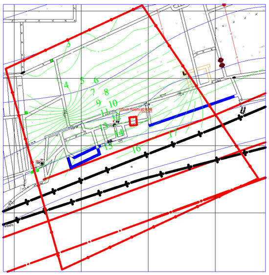
Figure 1.
Isopach map of the coal seam within the coal pillar area.
2.2. Main Shaft Overview
As shown in Figure 2, the main shaft serves as the intake shaft for the mine and also performs the coal hoisting function. The shaft has a designed diameter of 4.0 m and a total depth of 228 m. The entire shaft wall is constructed using a monolithic concrete structure, with a support thickness of 350 mm in the bedrock section and a total shaft wall thickness of 500 mm. The shaft is equipped with a pair of 1.5 ton skips and uses a steel wire rope conveyance system. A metal ladder-way is installed inside the shaft, which also serves as a mine safety exit.
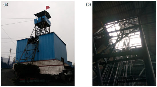
Figure 2.
Main shaft. (a) Exterior of the shaft. (b) Interior of the shaft.
3. Mining-Induced Deformation Prediction and Monitoring
3.1. Strip Mining Parameters
Based on the geological and mining conditions of the mining area, as well as the experience of mining beneath buildings in the area, and taking into account the characteristics of coal seam burial, the mining width is designed to be as large as possible while ensuring that surface damage does not exceed Grade I destruction [35,36]. This design aims to improve efficiency, reduce the excavation rate, and minimize the number of face relocations. Considering the existing production system and the need to keep shaft mining-induced damage within acceptable limits while maximizing coal recovery, the final scheme is outlined in Table 1.

Table 1.
Strip mining design parameters.
3.2. Predicted Parameters for Surface Deformation Using the Probability Integral Method
To analyze the surface displacement and deformation patterns caused by strip mining and to scientifically assess the impact of mining activities on surface structures such as the shaft and shaft frame, surface displacement and deformation calculations are essential. There are several methods for calculating surface displacement values induced by underground mining, including the typical curve method, negative exponential function method, and probability integral method. Based on field surveys and data analysis, an investigation into the overlying rock layers in the Longxiang Coal Mine area, including the presence of critical layers, was conducted. The surface subsidence pattern in this region generally conforms to the probability integral method model. For this study, the probability integral method will be used to predict surface displacement and deformation after mining at each working face.
According to the basic principles of the probability integral method, several key parameters are required for prediction, including the subsidence coefficient (q), the tangent of the main influence angle (tanβ), the horizontal displacement coefficient (b), the mining influence propagation angle, and the inflection point offset distance (s). The determination of these parameters is strongly influenced by the lithology of the overburden, regional geological conditions, and mining technology. In this study, the values were selected by integrating (i) long-term surface movement observations from the Longxiang Coal Mine and adjacent coalfields with similar stratigraphic settings, and (ii) empirical ranges reported in previous studies under comparable mining depths and rock mass properties [2,10]. Specifically, q = 0.87 was chosen as the average subsidence coefficient obtained from measured data in the study area, reflecting the relatively high degree of strata movement in shallow thick seams. tanβ = 2.4 was adopted based on statistical values observed in monitoring records of nearby mines with medium-hard overburden. The inflection point offset distance was assumed as s = 0 due to the symmetric geological conditions, while the mining influence propagation angle was taken as θ = 88°, consistent with the steep propagation characteristics of subsidence in this region. The horizontal displacement coefficient was set as bc = 0.34, following calibration against measured horizontal displacement data. These selections ensure that the prediction parameters are both site-specific and theoretically consistent, thereby enhancing the reliability of the subsequent subsidence calculations.
3.3. Prediction Based on New Probability Integral Method with Disturbance from Small Working Faces
This section incorporates existing monitoring data together with the actual mining positions of the working faces, while fully considering the variations in coal seam thickness across different regions and the temporal effects of progressive extraction. Owing to the relatively shallow burial depth, the large thickness of the coal seam, and the unstable depositional conditions at Longxiang Coal Mine, the ground surface is particularly sensitive to mining-induced disturbances. Field observations show that once subsidence initiates at a point, it quickly enters an active deformation stage, which complicates the parameter selection in the probability integral method [4,5]. Moreover, the monitoring results reveal that the duration of subsidence differs significantly between locations, ranging from only a few days to several months.
To overcome these challenges, a refined subsidence prediction approach was developed by integrating superposition theory with the probability integral method. In this approach, each large working face was subdivided into smaller computational panels according to mining progress and seam thickness variations. For each sub-panel, the surface displacement and deformation were first calculated independently using the probability integral method. Then, the principle of superposition was applied by overlaying the incremental deformation fields from all sub-panels, both spatially and temporally. This procedure enabled the cumulative effect of successive mining activities to be captured more accurately. In practice, with iterative adjustments of the subsidence coefficient to align the predicted values with monitoring data. Through this stepwise procedure, the model effectively reproduces the observed progressive and heterogeneous subsidence behavior in the field, thereby improving the reliability of prediction under complex geological conditions.
The 11062 working face is divided into 10 small working faces based on varying coal thickness and monthly progress, as shown in Figure 3. Since all monitoring points have reached final stability, the prediction adjusts the subsidence coefficient for different locations and provides the mining thickness for each section. The probability integral method is applied to the superposition of surface displacement predictions (Table 2).
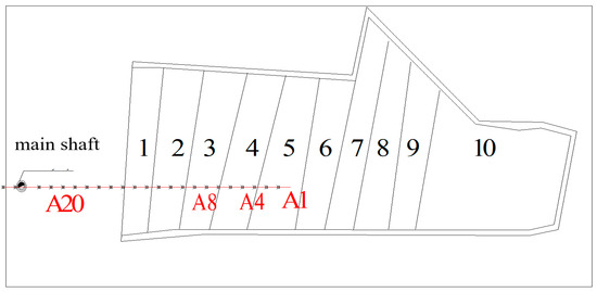
Figure 3.
Small working face model.
Table 2.
Predicted surface displacement and deformation parameters for each working face.
The subsidence coefficient is adjusted according to the actual monitored subsidence results. However, since the observation phase at the monitoring stations represents only one stage of surface movement and has not yet fully concluded, there is a tendency for the predicted results to be slightly overestimated.
Using the predicted surface displacement and deformation parameters from Table 2, the 11071 gob area is divided into 10 regions. After performing the calculations, the predicted results were processed and visualized using Surfer 16.0, which was applied both for overlay calculations of subsidence from individual sub-panels and for generating the final contour maps. The corresponding contour maps for surface subsidence, surface strike deformation, and surface subsidence basin are provided, as shown in Figure 4, Figure 5 and Figure 6.
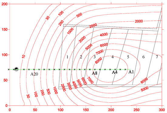
Figure 4.
Surface subsidence contour map for working face 11071 based on the superposition theory (units: mm).
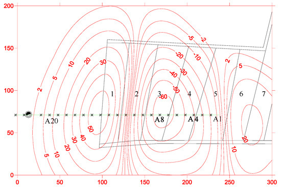
Figure 5.
Surface strike deformation contour map for working face 11071 based on the superposition theory (units: mm/m).
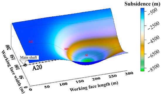
Figure 6.
Surface subsidence basin for working face 11071 based on the superposition theory.
3.4. Shaft and Surface Deformation Monitoring Design
To protect key structures such as the main shaft and hoist house at Longxiang Coal Mine, and to minimize the impact of mining activities on these structures while effectively reducing the loss of underground coal resources, it is essential to study the surface displacement and deformation patterns caused by underground mining. The process of surface displacement and deformation is highly complex, as it results from the combined influence of various geological and mining factors. Given that the deformation characteristics of the shaft under mining-induced surface movement have not yet been fully understood under these complex geological and mining conditions, a comprehensive monitoring system must be established. This system should primarily monitor the shaft and surface displacement, with supplementary monitoring of surface movement at nearby structures. The system will employ GPS static techniques, high-precision geometric leveling methods, and other observation techniques to create a three-dimensional surface displacement and deformation monitoring network. This will summarize the movement and deformation characteristics under mining influence, providing valuable data for further recovery operations.
Thus, surface displacement observation stations and building observation stations must be established above the working faces. The purpose of the surface displacement observation stations is to measure the maximum displacement and deformation caused by strip mining; the building observation stations aim to protect important surface structures. A substantial amount of real-time data will be obtained from these stations, which will then be analyzed to identify the influence patterns of various geological and mining factors on surface displacement and deformation. This will lay a solid and reliable foundation for the study of the recovery plan and protection technology for the main shaft at Longxiang Coal Mine.
The main shaft coal pillar at Longxiang Coal Mine is flanked by the existing 11062A and 11071 working faces. In this region, particularly near the main shaft, the coal thickness exceeds 12 m, and in some areas, it surpasses 16 m. The average burial depth of the coal seam is 211 m. In the strike direction, the working faces have undergone full mining disturbance, while in the dip direction, the mining disturbance has not yet reached full extent.
The purpose of establishing surface displacement observation stations is to measure the maximum surface displacement and deformation caused by strip mining. Therefore, the design of the observation stations is located along the main fault of the surface subsidence basin. The type of observation station is a profile-line-based standard surface displacement monitoring station, and the primary objective is to study the surface displacement and damage patterns. According to the guidelines in Coal Mining Damage and Protection, for the arrangement of profile-line observation stations, and based on the actual geological and mining conditions of the 11062A and 11071 working faces, the strike length-to-average mining depth ratio is greater than 1.4, indicating that the working faces have undergone full mining disturbance in the strike direction. However, the dip direction has not yet reached full disturbance. Consequently, the strike observation line is positioned along the main fault in the strike direction, with the observation line placed a certain distance d below the center of the gob area, towards the downhill direction.
The calculation results show that d = 42 m. The position of the strike observation line is determined on the inclined main fault, as shown in Figure 7.
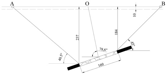
Figure 7.
Dip observation line profile.
The length of the strike observation line is determined along the strike main fault, as shown in Figure 8.
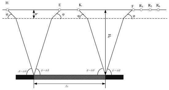
Figure 8.
Strike observation line profile.
When the working face advances along the strike direction, in order to ensure that the observation line is not affected by mining activities in nearby working faces, the strike observation line is typically set as half a line. The length of the strike observation line is calculated using the following formula:
where h—thickness of the overburden layer, approximately 10 m; φ—angle of horizontal displacement in the loose layer, 45°; H0—average mining depth, 211 m; δ—strike displacement angle, taken as 65°; l3—strike length of the working face, 280 m; Δδ—correction value for the strike displacement angle, since the working face in the strike direction has not undergone full mining disturbance, taken as 20°.
The strike length Lstrike is approximately 351 m. Based on the above, it is noted that the strike observation line length is approximately 351 m, and there is overlap between the two working faces along the observation line. Considering that the primary objective of Longxiang Coal Mine is to recover the coal pillars protecting the main shaft, only the observation line near the main shaft will be selected for actual monitoring.
Typically, the number and density of observation points along the observation line are determined based on the mining depth of the working face and the purpose of the observation stations. The observation points are set along the expected surface subsidence basin, generally starting from the center of the subsidence basin and extending outward toward the boundary. The average mining depth for the 11062 and 11071 working faces is approximately 211 m, with a point spacing of 10 m. Based on this analysis, the design type for the observation stations along the two wings of the shaft is a profile-line-based standard surface displacement monitoring station. One strike observation line, with a length of 372 m and a point spacing of 10 m, is established, resulting in 37 observation points along the strike observation line.
In addition, to monitor the impact of mining activities on the surface displacement and deformation of the main shaft and the changes around the hoist house, two observation lines, each 45 m in length, are set along the inclined direction at 45 m and 57 m on both wings of the main shaft. The point spacing is set to 15 m, resulting in eight monitoring points around the main shaft and six monitoring points around the hoist house. Therefore, excluding control points, a total of 66 observation points need to be installed at the monitoring stations. The surface topography of the observation station is shown in Figure 9.
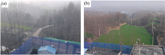
Figure 9.
Surface topography near the main shaft. (a) Western side of the shaft; (b) eastern side of the shaft.
3.5. Field Monitoring and Surface Survey
Through regular observations of the surface observation stations, a substantial amount of data was collected, which was then organized and analyzed to study the surface displacement and deformation characteristics, as well as the angular parameters. Surface observation stations were established on the east and west wings of the main shaft at Longxiang Coal Mine. on 6 December 20xx. Comprehensive monitoring began on 12 December, 20xx (as shown in Figure 10), and the initial planar and elevation coordinates of the observation points were obtained. For the first month, comprehensive monitoring was conducted weekly. After 15 January, 20xx, comprehensive monitoring was conducted every 30 days. The subsidence values for each measurement point along the strike observation line are shown in Table 3 and Table 4.
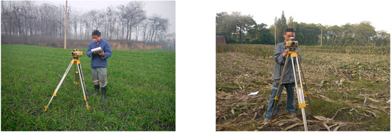
Figure 10.
Surface deformation monitoring and measurement due to mining disturbance.
Table 3.
Subsidence along the strike observation line on the east side of the shaft.
Table 4.
Subsidence along the strike observation line on the west side of the shaft.
Surface tilt refers to the ratio of the vertical subsidence difference between two adjacent points and their horizontal distance, reflecting the slope of the subsidence basin along a specific direction. Based on the measured data from the strike observation line on the east side of the shaft, and following the definition of tilt, the tilt values at each measurement point along the strike observation line on the east side of the shaft at different observation times can be calculated. These values are shown in Table 5.
Table 5.
Tilt at strike observation points.
Near the location of maximum subsidence, the tilt value is approximately zero. However, at the maximum subsidence point, the tilt is not zero due to variations in coal seam thickness, which increases gradually from the gob area toward the mining face. Moving from the maximum subsidence point in the direction of the working face, the tilt value generally increases initially and then decreases, which aligns with the typical subsidence pattern in the strike direction. The abrupt changes in some values are likely caused by uneven coal seam thickness. For the strike observation line on the west side of the shaft, prior to its installation, mining had already ceased in the 11062 working face. During monitoring, the subsidence on the west side occurred at a slower rate compared to the east side of the shaft.
Since the average mining depth in the strike direction is 192 m and no actual measurements of the loose layer movement angle are available for this mining area, a value of 45° is used for calculation. The thickness of the loose layer is approximately 10 m. Based on these three parameters, the horizontal deformation curve, tilt curve, and curvature curve are plotted (Figure 11). After analysis, the integrated strike movement angle for Zhengxin Longxiang Coal Mine is found to be 63.0°. The calculated value is slightly lower, which is related to the repeated mining disturbance in the 11071 working face.
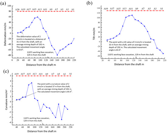
Figure 11.
Surface deformation curves. (a) Horizontal deformation curve; (b) tilt curve; (c) curvature curve. The red line represents the monitoring line, which is used to track and measure specific parameters along a defined path. The blue line corresponds to the mining-induced deformation along this monitoring line.
Continuous monitoring of control points around the shaft indicated that these points, due to their distance from the mining face, were not affected by mining disturbances. Based on the layout of the observation points, regular observations were conducted. During each observation period, investigations were carried out regarding the ground fissures and the condition of buildings above the 11062 and 11071 working faces. The damage observed is shown in Figure 12.
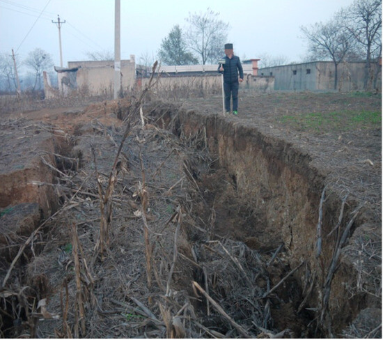
Figure 12.
Surface damage condition above the 11071 working face.
Through on-site observations, it was found that during the recovery period of the 11062 and 11071 working faces, surface buildings were severely damaged. According to the “Damage Classification for Masonry Structures” in the Regulations on the Retention of Coal Pillars for Buildings, Water Bodies, Railways, and Major Shafts and the Extraction of Coal Pillars (2000 edition), the maximum surface displacement and deformation observed during the mining of the 11062 working face greatly exceeded the Grade IV protection standard for buildings, causing severe adverse effects on the safety and usability of surface structures. Ground fissures were well-developed, with the maximum width of permanent fissures on the edges exceeding 1500 mm. Stepping subsidence was observed above the 11071 working face, with step heights ranging from 400 to 1600 mm. The stepped ground fissures were located entirely outside the working face mining boundary and the cessation line. These fissures exhibited a “strip-like” parallel distribution within the mining boundary, with the direction of fissure extension orthogonal to the main tensile direction of surface deformation. Above the cessation line of the 11062 working face, the stepped fissures were arcuate, generally parallel to the cessation line direction. The step height of the fissures ranged from 80 to 300 mm, and the maximum fissure width reached 300 mm. The distance between the two stepped fissures was approximately from 2 to 4 m. These stepped fissures were always ahead of the working face mining position by about 4 m, with an advance angle of approximately 88°. This phenomenon reflects the fact that the coal seam thickness in the working face is relatively large and the mining progress is slow, which is consistent with the measured surface results.
3.6. Shaft Monitoring and Maintenance Recommendations
The overlying rock (or soil) layers within the mining-induced disturbance zone experience horizontal and vertical displacements, which are transmitted to the shaft wall, causing coordinated deformation between the shaft wall and the surrounding rock mass. This is particularly critical when the hardness of the shaft wall and surrounding rock mass is similar. When vertical deformation reaches the limit strain of the shaft wall material, the shaft wall may experience vertical stretching or compressive failure. Over the years of operation, the shaft wall has undergone damage and deformation. To investigate the form and extent of this damage and to prevent falling concrete from damaging underground equipment, which could pose safety hazards and disrupt normal production, regular monitoring of the main shaft is conducted (as shown in Figure 13). Based on the observed conditions and the potential damage from the mining scheme, repair and reinforcement plans will be proposed to address the damaged areas and ensure the shaft’s continued functionality for future production.
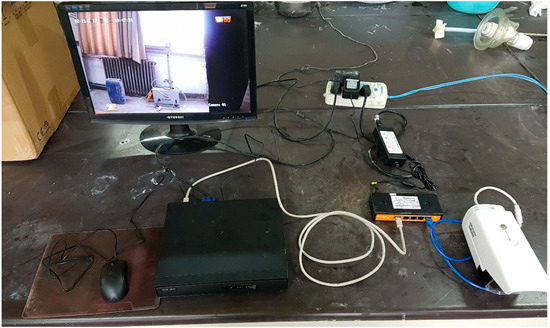
Figure 13.
Layout of the developed monitoring system.
Using video footage and recorded raw data, screenshots of the entire shaft wall damage observation were taken, as shown in Figure 14.
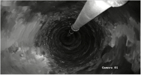
Figure 14.
Shaft wall damage observation map.
The observation results were compiled, and, based on the different screenshots, the damage to the main shaft wall was assessed. The results are shown in Table 6.
Table 6.
Summary of shaft wall site observations.
From the summary table of the site observation results of the main shaft wall, it can be seen that there are issues such as peeling, layer separation, spalling, and water seepage in certain areas of the main shaft wall at Zhengxin Longxiang Coal Mine, though the overall condition remains good. These observations provide reliable field data for the maintenance and contingency planning of the shaft.
During the coal pillar recovery process, different forms of deformation and damage to the shaft wall can be summarized as follows: the deformation and damage caused by mining are mainly concentrated in the weak layers surrounding the shaft, such as coal seams, mudstone, or fault fracture zones. During the coal pillar recovery, when localized damage occurs to the shaft wall, the damaged rigid shaft wall can be completely excavated down to the surrounding rock. The cavity can then be filled with compressible wooden blocks, ensuring that the deformation is controlled within the predetermined location, providing a basis for subsequent shaft wall deformation remediation. Alternatively, a pressure relief slot can be installed to release and attenuate the vertical additional stresses acting on the shaft wall, ensuring the safe operation of the shaft. The design and construction of the pressure relief slot should be completed prior to the coal pillar recovery.
4. Discussion
4.1. Comparison Between Predicted and Monitored Data
According to the comparison between the monitored data (Table 7, Figure 15) and the predicted results obtained by the probability integral method, the prediction shows a reasonable level of agreement with the measurements, with deviations ranging from 6.4 to 399.1 mm. In the section between observation points A1 and A5, subsidence can be regarded as sufficient, and the percentage error ranges from approximately 1.1% to 3.5%. In the section from A6 to A20, where subsidence was insufficient, the error ranges from 3.5% to 33.5%. Because the mined coal seam exhibits significant thickness variability, with some areas exceeding 16 m, the error in the fully mined zones remains within the acceptable range. The main reasons for the overall discrepancies in the subsidence curves are as follows: First, in the probability integral method, parameters such as seam dip angle, burial depth, and thickness were taken as average values, which inevitably differ from the actual heterogeneity of these factors. Second, when applying the superposition theory, the mined-out panel was subdivided into ten smaller panels, and the parameters used were selected as closely as possible to the monitored values; however, unavoidable mismatches between the assumed and actual spatial–temporal mining relationships still occurred. Third, since the monitoring period lasted for only one year, surface subsidence had not fully stabilized. Residual deformation will continue to contribute to further subsidence over time, which explains why the monitored results were smaller than the predicted ones.
Table 7.
Comparison between predicted and monitored subsidence data.
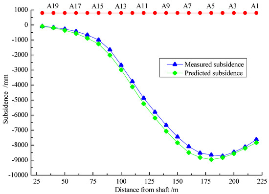
Figure 15.
Comparison between monitored and predicted subsidence curves.
4.2. Limitations
This study, taking the shaft coal pillar recovery of Longxiang Coal Mine as the engineering background, carried out strip mining design and subsidence prediction analysis, and obtained valuable results. However, several limitations remain. This study is based on a single case, and, therefore, the derived parameters should be regarded as site-specific. The results are most reliable under geological and mining conditions broadly comparable to those at the Longxiang Coal Mine. Application of the proposed method to other sites with different depths, seam characteristics, or overburden properties will require recalibration and further validation. First, this case study is confined to a single representative closed mine with comparatively simple geological structures, without incorporating dynamic analyses under faulted conditions [37,38,39,40,41,42,43,44,45,46,47,48]. The applicability of the conclusions to other mining areas with greater burial depths, more complex structures, or multiple overlapping seams requires further verification. Second, the subsidence prediction mainly employed the probability integral method combined with superposition theory. Although this approach has advantages in terms of computational efficiency and general applicability, it cannot fully capture stress concentration and localized damage around the shaft under heterogeneous rock mass conditions. Interruptions in mining on the 11071 working face caused deviations between the observed surface deformation and the patterns expected under uniform retreat mining. This study did not investigate in detail the deformation characteristics associated with non-uniform mining progress. Moreover, due to significant coal seam thickness variations beneath the shaft, existing research provides limited insights into the stability of coal pillars and surface deformation under such conditions. Furthermore, coal seam thickness heterogeneity is a key factor influencing prediction accuracy and partly explains the discrepancy between predicted and monitored values. Future work should therefore consider more detailed seam characterization to reduce this uncertainty.
5. Conclusions
This study, taking the shaft coal pillar recovery of Zhengzhou Coal Group Longxiang Coal Mine as the engineering background and drawing upon successful cases of shaft pillar extraction, systematically carried out subsidence prediction, mining-induced damage analysis, and safety control under strip mining conditions. The research combined theoretical calculations, probability integral method predictions, and field monitoring. The main conclusions are as follows:
By introducing superposition theory into the probability integral method, a subsidence prediction approach applicable to strip mining was established. The predicted subsidence values differed from the measured results by 6.4–399.1 mm, demonstrating that the method can reasonably capture subsidence patterns under complex geological conditions and validating its engineering applicability. Through analysis of surface movement in shallow and thick coal seams, the parameters of the surface movement angle were obtained, with the comprehensive strike movement angle determined as 63.0°. Disturbance induced by strip mining significantly altered the stress field around the shaft, with the shaft wall exhibiting typical damage modes such as spalling, delamination, peeling, and water seepage.
A comprehensive technical framework of “Subsidence prediction–Monitoring–Safety control” was developed. By integrating surface subsidence monitoring with direct shaft observations, the study achieved full-process tracking of mining-induced damage and proposed targeted mitigation measures, including shaft wall reinforcement, optimization of strip mining parameters, and surface protection measures. This framework provides a systematic solution for shaft pillar recovery in closed mines.
Author Contributions
D.W.: data acquisition, processing, and analysis, writing of the first draft, and participation in discussions and revisions. Z.W.: data processing. Y.L.: designing of research methods, experimental design, etc. Responsible for planning and ensuring the integrity and accuracy of the research and revision of this paper. Y.W.: designing the research methods and experimental design. All authors have read and agreed to the published version of the manuscript.
Funding
This work was supported by the Major National Science and Technology Project for Deep Earth of China (2024ZD1003805), and National Natural Science Foundation of China (52504076).
Data Availability Statement
The original contributions presented in this study are included in the article. Further inquiries can be directed to the corresponding authors.
Acknowledgments
During the preparation of this manuscript, we received invaluable support from Wenbing Guo.
Conflicts of Interest
The authors declare no conflicts of interest.
References
- Guo, W.; Wang, Y. Research on the definition of high-intensity mining based on green mining and its index system. J. Min. Saf. Eng. 2017, 34, 616–623. [Google Scholar] [CrossRef]
- Sebbab, M.M.; El Ouahidi, A.; Ousbih, M.; Ouboulahcen, S.; Abdelrahman, K.; Abioui, M. Integrated geotechnical approach and GIS for identification of geological resources exploitable quarries for sustainable development in ifni inlier and lakhssas plateau (western anti atlas, morocco). Appl. Sci. 2023, 13, 3932. [Google Scholar] [CrossRef]
- Guo, W.; Li, Y.; Liu, D. Technology of variable-width strip mining under densely built industrial squares. J. Henan Polytech. Univ. 2017, 36, 8–14. [Google Scholar] [CrossRef]
- Wu, L. Theory and Practice of Coal Pillar Recovery Under Buildings; China University of Mining and Technology Press: Xuzhou, China, 1994. [Google Scholar]
- Zhang, P. Research on Shaft Pillar Recovery Damage Characteristics and Control Technology Under Industrial Squares. Master’s Thesis, Henan Polytechnic University, Henan, China, 2009. [Google Scholar]
- Gao, H.; An, B.; Han, Z.; Guo, Y.; Ruan, Z.; Li, W.; Zayzay, S. The sustainable development of aged coal mine achieved by recovering pillar-blocked coal resources. Energies 2020, 13, 3912. [Google Scholar] [CrossRef]
- Yang, X.; Hou, L.; Xue, H.; Yuan, D.; Cao, J.; Han, Z.; Gao, Y. Pressure distribution and deformation control of gob-side entry retaining formed by roof cutting influenced by abandoned roadways. Geotech. Geol. Eng. 2021, 39, 2533–2545. [Google Scholar] [CrossRef]
- Li, J.; Wang, W.; Yao, H.; Yan, J.; Pei, Z. Study on the law and control mechanism of slope sliding instability under hanging wall coal mining. Adv. Civ. Eng. 2025, 1, 7884079. [Google Scholar] [CrossRef]
- Sun, Z.; Zhao, Y.; Bolz, P.; Côte, C.; Ren, J. A multimethod GIS-based framework for site selection of underground pumped storage power stations using closing coal mines: A case study of the Shanxi province, China. Renew. Energy 2025, 243, 122521. [Google Scholar] [CrossRef]
- Yu, Q.; Ma, J.; Shimada, H.; Sasaoka, T. Influence of coal extraction operation on shaft lining stability in eastern Chinese coal mines. Geotech. Geol. Eng. 2014, 32, 821–827. [Google Scholar] [CrossRef]
- Li, W.; Duan, H.; Xu, Y.; Du, M. The stability evaluation of shaft during drastic drawdown dewatering of alluvium. Shock Vib. 2019, 2019, 3090439. [Google Scholar] [CrossRef]
- Zhao, Y.; Feng, Z. A brief introduction to disaster rock mass mechanics. Geohazard Mech. 2023, 1, 53–57. [Google Scholar] [CrossRef]
- Wang, W.; Yao, Q.; Wang, A.; Hudson-Edwards, K.A.; Zheng, C.; Yan, L.; Dai, L.; Liu, Y. Study of a damage constitutive model for water-bearing coal measures sedimentary rock with nonlinear deformation during compaction stage. Geohazard Mech. 2023, 1, 244–254. [Google Scholar] [CrossRef]
- Du, C.; Wang, X.; Pan, Y.; Yin, X. A novel evaluation model of shaft stability based on combination weighting method and Promethee II decision-making algorithm. Arab. J. Geosci. 2022, 15, 682. [Google Scholar] [CrossRef]
- Jha, P.; Kumar, S. Simplified approach to estimate lateral load on drilled shafts resulting from a heavily loaded adjacent shallow foundation using horizontal stress isobars. Int. J. Geomech. 2016, 16, 04015032. [Google Scholar] [CrossRef]
- Rong, J.; Wang, B. Deformation and instability mechanisms of a shaft and roadway under the influence of rock mass subsidence. Appl. Sci. 2025, 15, 163. [Google Scholar] [CrossRef]
- Zhao, Q.; Yin, J.; Fu, B. Deformation mechanism and control technology of the surrounding rock of the floor roadway under the influence of mining. Adv. Civ. Eng. 2020, 2020, 6613039. [Google Scholar] [CrossRef]
- Tang, B.; Cai, H.; Cheng, H.; Lin, J.; Cao, G. Effect of seepage velocity on formation of shaft frozen wall in loose aquifer. Adv. Mater. Sci. Eng. 2018, 2018, 2307157. [Google Scholar] [CrossRef]
- Cai, H.; Yao, F.; Hong, R.; Lin, J.; Zeng, K. Multi-loop pipe freezing optimization of deep shaft considering seepage effect. Arab. J. Geosci. 2022, 15, 153. [Google Scholar] [CrossRef]
- Liu, Y.; Zhao, H.; Wang, A.; Dai, L.; Li, Y.; Zhang, H. Influence of cyclic dynamic disturbance on damage evolution and zoning effect of coal-rock under local static load constraint. Geohazard Mech. 2023, 1, 263–276. [Google Scholar] [CrossRef]
- Fujii, Y.; Ishii, Y.; Goto, T.; Ito, Y. A study on shaft damages due to mining. J. Min. Mater. Process. Inst. Jpn. 1995, 111, 993–1000. [Google Scholar] [CrossRef]
- Yan, H.; Zhang, J.; Zhang, S.; Zhou, N. Physical modeling of the controlled shaft deformation law during the solid backfill mining of ultra-close coal seams. Bull. Eng. Geol. Environ. 2019, 78, 3741–3754. [Google Scholar] [CrossRef]
- Taira, M. The end process of the Joban coalfield Ibaraki: A case of closure measure for Takahagi Coal Mine Co. Ltd. Kushigata Mining Station. Jpn. J. Reg. Policy Stud. 2015, 14, 108–115. [Google Scholar] [CrossRef]
- Cole, M.J.; Mthenjane, M.; Van Zyl, A.T. Assessing coal mine closures and mining community profiles for the just transition’ in south africa. J. S. Afr. Inst. Min. Metall. 2023, 123, 329–342. [Google Scholar] [CrossRef]
- Li, P.; Zhu, X.; Ding, X.; Zhang, T. An experimental study of industrial site and shaft pillar mining at Jinggezhuang coal mine. Appl. Sci. 2023, 13, 2340. [Google Scholar] [CrossRef]
- Szlązak, N.; Korzec, M. Conditions that determine changing the function of mine shafts in a gassy coal Mine—A case study. Energies 2024, 17, 1379. [Google Scholar] [CrossRef]
- Yang, W.; Hu, C.; Zou, J.; Han, J. Deflection mechanism and safety analysis of coal mine shaft in deep soil strata. Math. Probl. Eng. 2019, 2019, 9461742. [Google Scholar] [CrossRef]
- Zhou, B.; Li, S.; Kang, J.; Zhang, L.; Zhang, J.; Li, M. A probability integral method modified model for accurately characterizing subsidence at the boundary of a mining area. Sci. Rep. 2025, 15, 21014. [Google Scholar] [CrossRef] [PubMed]
- Wang, J.; Wu, S.; Wang, Z.; Barbaryka, A.; Tost, M.; Li, M. New Prediction Method of Subsidence Based on the Numerical Displacement Analysis: A Study Case of Deep-Buried Thick Alluvial Layer and Thin Bedrock. Rock Mech. Rock Eng. 2025, 58, 6723–6744. [Google Scholar] [CrossRef]
- Wang, L.; Cheng, Y.; Ge, C.; Chen, J.; Li, W.; Zhou, H.; Hai-feng, W. Safety technologies for the excavation of coal and gas outburst-prone coal seams in deep shafts. Int. J. Rock Mech. Min. Sci. 2013, 57, 24–33. [Google Scholar] [CrossRef]
- Xu, Y.; Li, X.; Jie, Y. Test on water-level stabilization and prevention of mine-shaft failure by means of groundwater injection. Geotech. Test. J. 2014, 37, 319–332. [Google Scholar] [CrossRef]
- Guo, W.; Zhao, G.; Bai, E.; Guo, M.; Wang, Y. Effect of overburden bending deformation and alluvium mechanical parameters on surface subsidence due to longwall mining. Bull. Eng. Geol. Environ. 2021, 80, 2751–2764. [Google Scholar] [CrossRef]
- Guo, W.; Tan, Y.; Bai, E. Top coal caving mining technique in thick coal seam beneath the earth dam. Int. J. Min. Sci. Technol. 2017, 27, 165–170. [Google Scholar] [CrossRef]
- Bai, E.; Guo, W.; Tan, Y. Negative externalities of high-intensity mining and disaster prevention technology in China. Bull. Eng. Geol. Environ. 2019, 78, 5219–5235. [Google Scholar] [CrossRef]
- Bai, E.; Guo, W.; Zhang, H.; Tan, Y.; Li, X.; Wei, Z. Degradation mechanism of cultivated land and its protection technology in the central coal-grain overlapped area of China. J. Clean. Prod. 2024, 468, 143075. [Google Scholar] [CrossRef]
- Bai, E.; Wang, R.; Guo, W.; Tan, Y.; Lei, W.; Li, H.; Wei, Z. Green coal mining technology of overburden grout injection with directional drilling under buildings. Bull. Eng. Geol. Environ. 2025, 84, 391. [Google Scholar] [CrossRef]
- Li, Y. Fault quasi-static and dynamic ruptures in deep coal mining: Impacts on working faces. Bull. Eng. Geol. Environ. 2024, 83, 515. [Google Scholar] [CrossRef]
- Li, Y.; Fukuyama, E.; Yoshimitsu, N. Comprehensive 3-D modeling of mining-induced fault slip: Impact of panel length, panel orientation and far-field stress orientation. Rock Mech. Rock Eng. 2025, 58, 5961–5979. [Google Scholar] [CrossRef]
- Li, Y.; Yang, J.; Gao, X. Fault slip amplification mechanisms in deep mining due to heterogeneous geological layers. Eng. Fail. Anal. 2025, 169, 109155. [Google Scholar] [CrossRef]
- Li, Y.; Fukuyama, E.; Yoshimitsu, N. Mining-induced fault failure and coseismic slip based on numerical investigation. Bull. Eng. Geol. Environ. 2024, 83, 386. [Google Scholar] [CrossRef]
- Li, Y.; Gao, X.; Yang, J.; Bai, E. Quantitative 3-D investigation of faulting in deep mining using Mohr–Coulomb criterion and slip weakening law. Geomech. Geophys. Geo-Energy Geo-Resour. 2025, 11, 1–24. [Google Scholar] [CrossRef]
- Li, Y. Heterogeneous layer effects on mining-induced dynamic ruptures. Comput. Geosci. 2025, 195, 105776. [Google Scholar] [CrossRef]
- Li, Y. Spatial distribution of strain energy changes due to mining-induced fault coseismic slip: Insights from a rockburst at the Yuejin coal mine, China. Rock Mech. Rock Eng. 2025, 58, 1693–1706. [Google Scholar] [CrossRef]
- Li, Y.; Gao, X. Assessment of variations in shear strain energy induced by fault coseismic slip in deep longwall mining. Int. J. Coal Sci. Technol. 2025, 12, 3–16. [Google Scholar] [CrossRef]
- Wang, X.; Hou, X.; Yuan, W.; Fan, C.H.H. Attenuation of blast-induced vibration on tunnel structures. Geohazard Mech. 2024, 2, 153–163. [Google Scholar] [CrossRef]
- Avulapalle, N.; Chenna, R.; Vemuri, J. Assessment of seismic retrofitting interventions in reinforced concrete structures. Geohazard Mech. 2023, 1, 194–202. [Google Scholar] [CrossRef]
- Li, Y.; Gao, X. Shear strain energy related to mining induced fault slip and its implications for rockbursts. Sci. Rep. 2025, 15, 15168. [Google Scholar] [CrossRef] [PubMed]
- Li, Y.; Gao, X. Quantitative analysis of ultra-close fault dynamic rupture and seismic risks in deep roadway excavation. Sci. Rep. 2025, 15, 8891. [Google Scholar] [CrossRef] [PubMed]
Disclaimer/Publisher’s Note: The statements, opinions and data contained in all publications are solely those of the individual author(s) and contributor(s) and not of MDPI and/or the editor(s). MDPI and/or the editor(s) disclaim responsibility for any injury to people or property resulting from any ideas, methods, instructions or products referred to in the content. |
© 2025 by the authors. Licensee MDPI, Basel, Switzerland. This article is an open access article distributed under the terms and conditions of the Creative Commons Attribution (CC BY) license (https://creativecommons.org/licenses/by/4.0/).