Article

A Verification Method for a Bay Configuration File of Intelligent Substation Renovation and Expansion in Power Systems

1
State Grid Heilongjia Electric Power Co., Ltd. Limited Extra High Voltage Company, Harbin 150000, China
2
School of Electricity and New Energy, Three Gorges University, Yichang 443002, China
*
Authors to whom correspondence should be addressed.
Processes 2025, 13(10), 3273; https://doi.org/10.3390/pr13103273
Submission received: 24 August 2025 / Revised: 16 September 2025 / Accepted: 23 September 2025 / Published: 14 October 2025

Abstract

New renovation and expansion projects of intelligent substations may cause frequent changes in the internal configuration of intelligent electronic devices, making it difficult for on-site inspection personnel to verify their configuration files. Therefore, this paper proposes an intelligent substation renovation and expansion project bay configuration file verification method based on cyclic redundancy check dynamic verification. Firstly, the logical relationship of configuration description files involved in the renovation and expansion project was introduced in detail, and bay decoupling and secondary circuit identification techniques were used to assign secondary equipment to bays. Then, the cyclic redundancy check dynamic verification method is introduced for the online diagnosis of configuration files and to manage and locate the secondary circuits associated with the bay of the renovation and expansion project. Finally, the semantic recognition method was used to verify the correctness of the virtual circuit configuration information. The effectiveness of the method was verified using a 220 kV substation in the Heilongjiang power grid as an example, which can effectively meet the application needs of intelligent substation renovation and expansion projects.

1. Introduction

With the large-scale promotion and application of intelligent substations, corresponding renovation and expansion projects are also being carried out simultaneously to form a transmission and distribution ring network to ensure the reliable supply of power [1,2,3,4]. The secondary circuit of an intelligent substation has been transformed from a hard-wired to a virtual circuit, which solves many problems of the original secondary circuit by sharing information at the process level [5,6,7]. However, it also makes the secondary circuit invisible. Moreover, the renovation and expansion project will cause frequent changes in the internal configuration of the intelligent electronic device (IED) of adjacent circuit breakers and bus bars, resulting in the verification of the renovation and expansion bay in the acceptance stage. It is also necessary to reverify the bay that is not involved in the renovation and expansion, which greatly increases the work intensity and potential risks of debugging and acceptance [8,9,10]. Therefore, it is urgent to develop a verification method for the bay configuration file of the intelligent substation renovation and expansion.
Regarding the above issues, scholars at home and abroad have reported many related research works and achievements [11,12,13,14,15,16,17,18]. The importance of station configuration description (SCD) files in the visualization and intelligent diagnosis of secondary systems in intelligent substations was analyzed, but their correctness was not discussed [12]. An SCD file automatic generation technology is proposed, which covers the entire process of station framework generation, virtual terminal automatic recognition, standard rule matching, and file verification to reduce configuration file error rates and accelerate configuration efficiency [13]. However, it failed to achieve information localization. A configuration file visualization checker based on the Linux system was built, which compares SCD files and bus protection configuration files before renovation and expansion by calling the core loop redundancy verification module [14]. However, the design process is relatively rough and cannot be accurately implemented. A recurrent neural network algorithm and Markov clustering algorithm for intelligent substation engineering configuration verification and comparison were used under the configuration file image control technology [15], but they could not achieve accurate positioning. The convolutional neural network was introduced as a method for the intelligent verification of SCD files in renovation and expansion projects. The superiority of the method was verified by checking the accuracy of the neural network using SCD for main transformer expansion, but a large number of samples were required [16,17]. The fault diagnosis method based on an improved Bayesian algorithm was proposed to improve the accuracy and maintenance efficiency of secondary circuit fault diagnosis in intelligent substations, but the implementation process is relatively cumbersome [18]. Rapid confirmation of the consistency of the protection device configuration file was achieved by comparing the consistency of sub-CRCs (cyclic redundancy check codes) before and after expansion and expansion based on domain partitioning [19,20], but the information change interval could not be located. The domain division of IEDs was carried out through CRC verification, and the testing boundaries of IEDs for renovation and expansion projects were obtained. The minimum sub-CRC consistency check was used to further narrow down the scope of transmission testing [21], but the accuracy of modifying associated interval files was not discussed. SCD files were physically decoupled into independent intervals and associated intervals to prevent SCD errors in independent intervals, which can greatly reduce the workload of acceptance and debugging [22]. However, physical decoupling generates multiple files, making version control more cumbersome. Engineering sub-blocks are divided based on the virtual connection status of IEDs in renovation and expansion projects and changes in communication parameters, and cyclic redundancy calculation is carried out based on configuration information to obtain engineering sub-block verification codes [23]. Then, the changed parts of the configuration file are located and verified.
In summary, this paper proposes an intelligent substation expansion bay configuration file verification method based on CRC dynamic verification. Firstly, the logical relationship of configuration description files involved in the renovation and expansion project was introduced in detail, and bay decoupling and secondary circuit identification techniques were used to assign secondary equipment to bays. Then, the CRC dynamic verification method is introduced for online diagnosis of configuration files and to control and locate the secondary circuits associated with the bay of the renovation and expansion project. Finally, semantic recognition methods were used to verify the correctness of virtual circuit configuration information, and the effectiveness of the method was validated using a 220 kV substation in the Heilongjiang power grid as an example.
This paper proposes an intelligent substation expansion interval configuration file verification method based on CRC dynamic verification, which can efficiently grasp the changes in the entire substation configuration file, quickly locate specific intelligent electronic devices, and meet the application needs of intelligent substation expansion projects. The main contributions of this work are as follows:
(1) Based on the logical relationship of the configuration description file for the renovation and expansion project, a model physical isolation method with independent intervals is used to avoid erroneous modification of irrelevant interval configuration information from the configuration source. Combined with secondary circuit identification technology, secondary equipment is allocated to intervals.
(2) Propose a secondary loop control method based on interval CRC to control the configuration interval information of Configured IED Circuit Description (CCD) files before and after renovation and expansion, ensuring direct positioning of the configuration information of associated interval devices, reducing transmission experiments for interval loops that have already been put into operation, and providing technical support.
(3) Using semantic recognition methods to verify the configuration information of virtual circuits and to verify the information of renovation and expansion intervals, providing verification methods for expansion configurations, and ensuring their correctness.

2. Analysis of Configuration Files for Intelligent Substations

The configuration file of the intelligent substation mainly includes the intelligent electronic device capability description (ICD) file, the intelligent electronic device instance configuration description (CID) file, the system specification description (SSD) file, and the whole SCD file. The SCD file is the dominant document for the entire intelligent substation under the IEC 61850 standard, which clarifies the logical relationship between the substation structure and the IEDs inside the station. It includes information on the entire station data model, IED instantiation configuration, communication parameters, and virtual circuit connection relationships. During the commissioning phase of the new line access of the substation reconstruction and expansion project, the commissioning personnel will frequently change the SCD file. The reconstruction and expansion of the line has a long cycle and involves a wide range of working areas, leading to the inability of on-site personnel to accurately understand the latest information and the inability to visually present the changed location. The logic structure diagram of the newly renovated and expanded bay and busbar protection circuit is shown in Figure 1. The supplier has developed some visualization tools to meet the on-site testing requirements, but the definition of the impact scope is not intuitive and specific enough, making it difficult to ensure that the modification of configuration information does not affect the correct operation of the secondary equipment that is currently running, and that incorrect modifications may affect the configuration information of other operating equipment, which cannot accurately guide the smooth progress of the renovation and expansion project [24]. To ensure the accuracy of SCD files, the scope of debugging secondary equipment is often expanded, and transmission experiments are conducted on each branch.
To reduce the workload of secondary system debugging and verification and ensure the accuracy of configuration files in unassociated areas, this paper adopts the bay decoupling method to partition the entire substation SCD file. The architecture of SCD file decoupling based on the bay is shown in Figure 2. The main process is as follows: Firstly, based on the analysis of the renovation and expansion scenario, the associated and unassociated bays in the SCD file before the renovation and expansion are determined, and global variables, such as IED name and IP, are saved in the configuration tool. Secondly, load the SCD file and decompose it into each bay configuration description file. The unassociated bay files are saved to the local device’s dedicated unassociated bay directory for physical isolation. Save the file of the associated bay to the local device’s dedicated associated bay directory for backup. Thirdly, refer to the saved global variables, such as the IED name and IP, and configure the configuration tool to modify the associated bay file. Fourth, compare and analyze the modified associated bay configuration information of the configuration tool with the backup associated bay for use in renovation and expansion. Fifth, merge the unassociated bay with the modified associated bay content to form a new SCD model, and perform integrity and consistency checks.
In the process of generating bay configuration description files by system integration personnel, if errors are made in the operation of the secondary device CCD file and are not detected, these errors will directly affect the normal operation of the device, leading to unpredictable situations. According to the Technical Specification for Intelligent Substation Secondary System Configuration Tool, CCD files can be exported from SCD files through the system configuration tool and downloaded to the device for effective operation. It is mainly used to define the subscription and publication of GOOSE and SV information for IEDs, including the mapping relationship between the internal addresses of virtual circuits and the addresses of external devices, control block communication parameter information, virtual terminal receiving-port information, and virtual terminal description information.
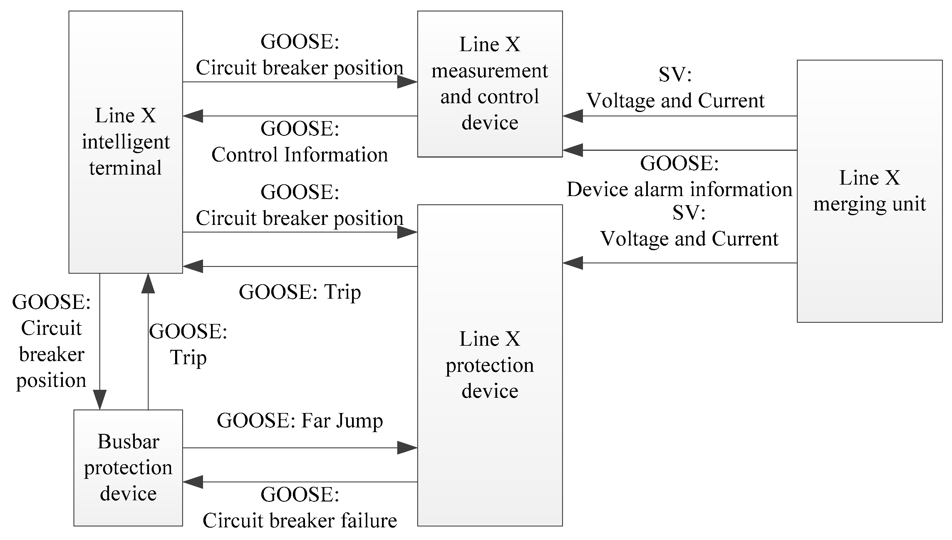
The process network, which integrates protection, measurement and control, merging units, and intelligent terminals, serves as the real-time information exchange center for intelligent substations. Real-time information, such as electrical sampling, switch status, and control instructions, is collected in the process layer through SV messages and GOOSE messages in the form of broadcasting. The associated bay devices achieve virtual connections for information exchange by subscribing to communication message control blocks in real time. The virtual connection relationship information of these messages is saved in the CCD file of the intelligent substation. The bus protection device can obtain and receive corresponding branch information and receive startup failure GOOSE signals. The line protection device can receive bus trip information and send circuit breaker failure signals. The measurement and control device can receive GOOSE signals from the merging units in the corresponding bay. The merging unit can send the SV current to the line protection device. Voltage signal: The intelligent terminal device can output a trip signal based on the GOOSE trip signal sent by the line protection device and provide feedback on the position of the circuit breaker. The corresponding secondary circuit topology is shown in Figure 3.

3. Configuration File Verification Method Based on CRC Dynamic Verification

3.1. Secondary Circuit CRC Code

Due to various factors, such as noise, the configuration files of smart substations are prone to bit errors during storage and data transmission. In order to ensure the accuracy of configuration file data, the configuration file performs error detection on the data. Only when the detection result is correct does it indicate that there is no data error problem in the intelligent substation configuration file, and the configuration file can be further applied. There are various ways to detect errors in the field of information, compared with advanced detection technologies, such as hash function or encryption check [25,26]; cyclic redundancy checks (CRCs) have become the best choice in line with the International Standard IEC 61850 and industry practice because of its high efficiency, hardware friendliness, and error detection ability to deal with such non-malicious errors. It can generate a short fixed-digit check code according to the data, such as network packets or computer files. Through the change in the check code, you can know whether the configuration file has changed in real time, and it is convenient to master the changes in the configuration file. It can generate a short fixed-digit check code based on network packets or computer files, and through the changes in the check code, real-time information can be obtained on whether the configuration file has changed, making it convenient to grasp the changes in the configuration file.
CRC verification first generates a frame check sequence (FCS) based on the generating polynomial g1(x), and adds FCS1 to the original data. Then, combined with another generating polynomial g2(x), a new FCS2 is obtained to generate the verification code. The calculation formula is shown in Formula (1) and Formula (2):
F C S 1 x = N D x · x r 1 mod g 1 x ,
F C S 2 x = N D x · x r 1 + F C S 1 x · x r 2 mod g 2 x ,
where ND represents a binary polynomial; r1 and r2 represent the lengths of the checksum, respectively.
Verification uses the same CRC algorithm to calculate the FCS of the original data and compare it with the FCS attached to the original data for consistency. At this time, the sent message sequence is T = [ND, FCS1, FCS2], with a length of m+ r1+ r2. Two related verifications are performed at the receiving end, and the calculation formula is shown in Formula (3) and Formula (4):
N D x · x r 1 + F C S 1 x mod g 1 x = 0 ,
N D x · x r 1 + F C S 1 x · x r 2 + F C S 2 x mod g 2 x = 0
Only when the above two verification formulas are valid can the integrity of the original data be confirmed.

3.2. CRC Dynamic Verification

On the basis of ensuring the integrity of the CRC configuration file, dynamic verification of the intelligent substation configuration file is implemented to ensure consistency between the CRC configuration file and the on-site operation of intelligent electronic devices. Dynamic verification mainly includes the following aspects:
(1) Verify through the CRC verification code of the online secondary IED. The main purpose is to obtain the CRC verification code of the IED configuration file and compare it with the CRC verification code in the standard CCD file of this site to verify the correctness of the IED configuration file.
(2) Verify by analyzing the messages sent by the secondary IED. The main task is to analyze the various fields contained in the message and compare them with the CCD file in the control system to verify the correctness of configuration information, such as MAC address, control block reference, dataset, identifier, configuration version, and entry.
(3) Through regular inspections and proactive verification. The main purpose is to set a timed or manually triggered method to verify whether the CRC code sent by the IED is consistent with the CRC code of the CCD file, thereby verifying the correctness of the configuration file.
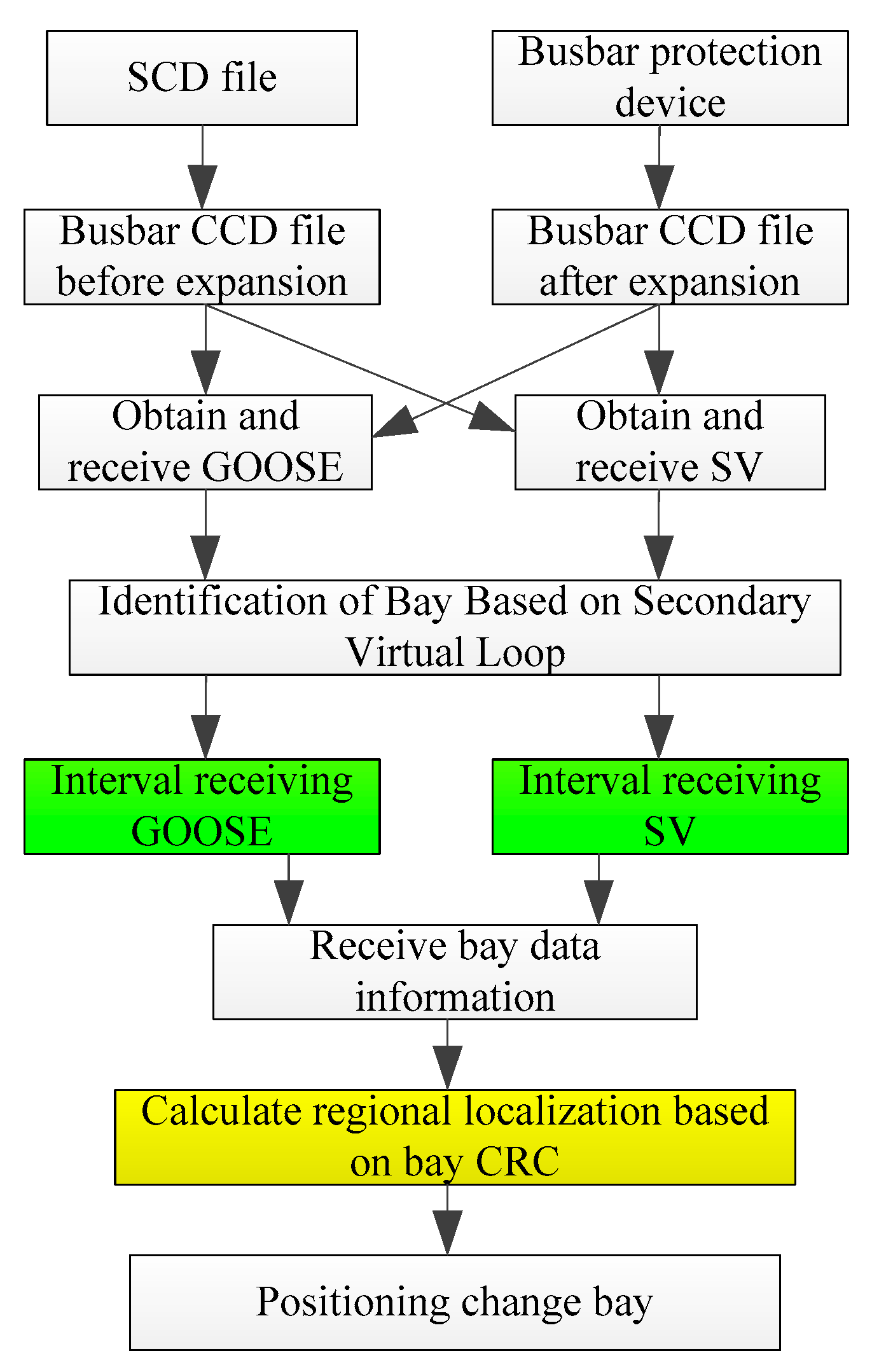
Considering that the configuration files of smart substations will become increasingly large in the future, and the time and computational space required for verification will be enormous, this article will combine the formation mechanism of smart substation configuration files and adopt a double-layer CRC verification method. According to the CCD file, the control block information is assigned to the bay based on the device name. Based on the bay information, all GOOSE and SV within the bay are obtained, sorted, and combined into a new piece of character sequence information. Finally, the CRC calculation is performed on the character sequence information. The double-layer CRC code fully utilizes the original check code of the existing substation configuration file to perform a secondary CRC on the original check code of the intelligent substation CCD file, forming a summarized CRC total value. By mastering the CRC total value, operation and maintenance personnel can quickly understand the changes in the file configuration of the entire substation. As long as the bay CRC value in the bus protection CCD file remains unchanged, the configuration information of the branch and bus protection will not change. By comparing the bay CRC values before and after the renovation and expansion, it can be determined whether the renovation and expansion affect the already operational lines. If there has been a change, the CRC value can be used to deduce the CRC code of each intelligent electronic device, thereby locating the intelligent electronic devices with status changes or inconsistent configuration files, and achieving the management of multiple intelligent substation configuration files, as shown in Figure 4.
When carrying out a renovation and expansion project, in order to avoid erroneous modifications to the operating or unassociated bay equipment caused by the expansion bay configuration, the impact range is defined and analyzed to narrow down the scope of intelligent substation expansion and commissioning. The positioning process for secondary circuit bay changes is shown in Figure 5.

3.3. Verification of Virtual Circuit Configuration Information for Associated Intervals

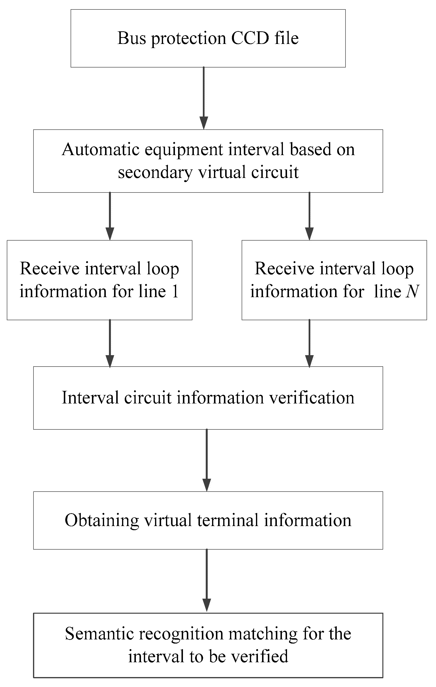
In actual smart substations, the same voltage level but different line intervals adopt the same secondary equipment configuration and design method, and the virtual circuit correlation relationship within the interval is basically the same. For the expansion interval, based on the configuration information of the secondary equipment that has been put into operation, verify whether the configuration method of the secondary equipment for the expansion interval is consistent and whether the logic is correct. Due to the similar basic principles of secondary circuit design in intelligent substations, a semantic recognition method based on keywords is proposed to automatically extract keywords and verify the correctness of virtual circuits [27]. When using semantic recognition methods for matching, the template information is first obtained based on the type and voltage level of the IED. Then, the virtual terminal information in the CCD file to be verified is obtained, and the keywords in the template are extracted for semantic recognition matching. The flow chart of virtual circuit information verification is shown in Figure 6.

4. Engineering-Application Examples

4.1. Project Overview

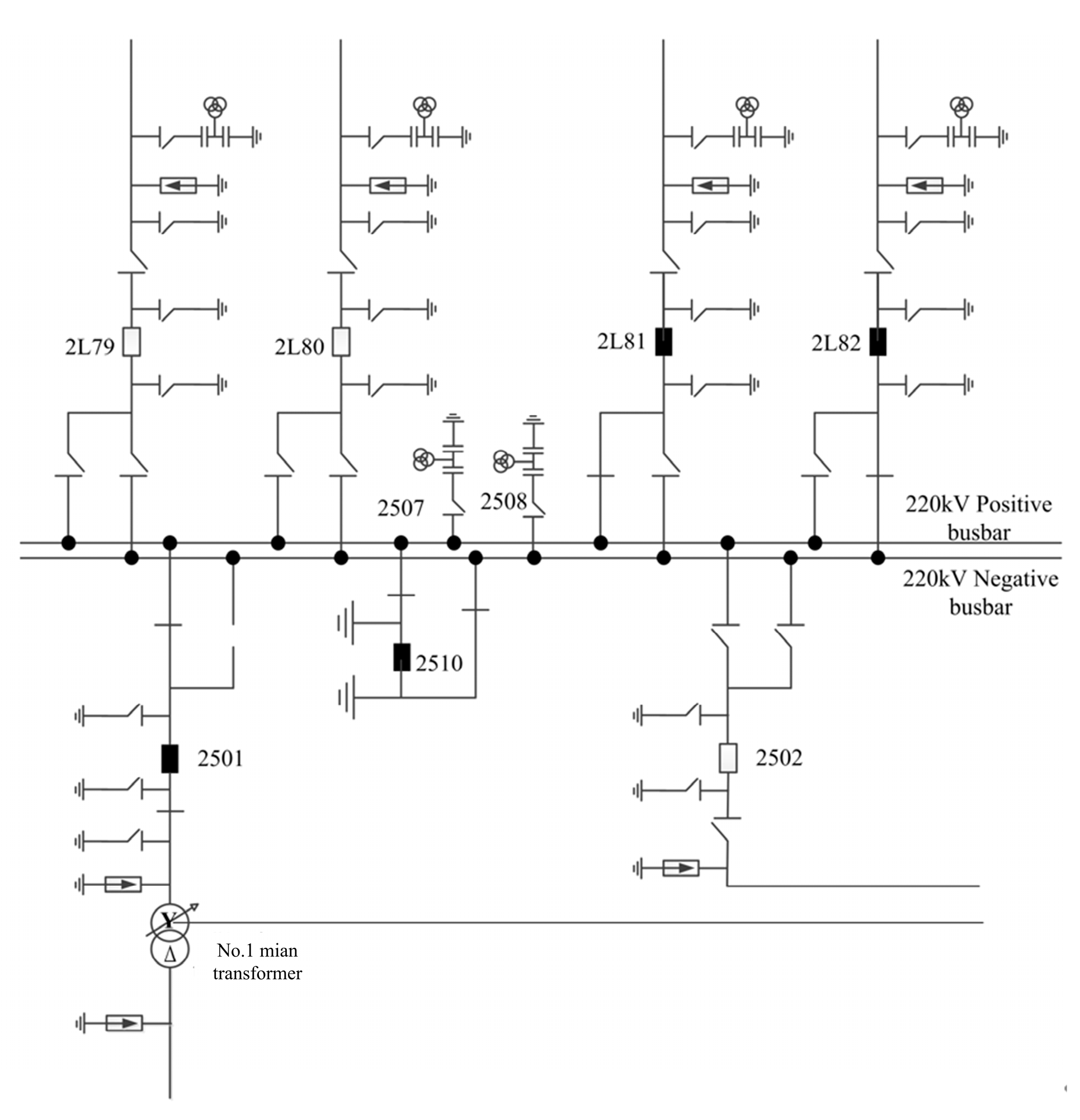
Taking a 220 kV intelligent substation in Heilongjiang Province as an example, the 220 kV primary main connection adopts a double busbar connection, as shown in Figure 7. There is currently one 220 kV #1main transformer and four outgoing lines. The secondary system in the station adopts typical SV sampling and GOOSE tripping modes. To improve the possibility of power supply, it is now necessary to expand the 220 kV #2 main transformer. The secondary system configuration file involves two sets of 220 kV bus differential protection, namely Nari technology nsr-371a bus protection and Nari relay protection pcs-915 produced by Nanjing Nari relay protection Co., Ltd., Nanjing, China.

4.2. Analysis of Configuration File Verification Based on CRC Dynamic Check

The virtual terminal and the receiving virtual terminal of each bus-protected bay device are sent to each other to generate and compare the modified CRC code, as shown in Table 1. As can be seen from Table 1, after the expansion, the first row represents the busbar protection, and the total CRC code sent does not change, because it is the maximum configuration. Lines 2, 3, and 4 are the CRC codes received by the first combination unit of the main transformer, the first protection group, and the first intelligent terminal in the busbar protection profile, respectively. Their CRC codes have changed because virtual terminals have been added between these devices and the busbar protection. Lines 5–12 indicate that the virtual terminal CRC code received at independent device bays does not change. The above CRC verification results are completely consistent with the theoretical expected values in Section 3.2 of the paper, which proves that the renovation and expansion project only modified the SCD file of the associated bay, and did not modify the unassociated bay, so there is no need to carry out transmission and other tests at the unassociated bay. At the same time, click the “No” text in Table 1 to display the inconsistent configuration information of the main transformer protection and intelligent terminal before and after modification in the busbar protection configuration file, which is convenient for engineers to further check and handle.

4.3. Method Comparison

The proposed method is compared with a Bayesian network [28], sub-CRC [21], decision tree algorithm [29], and convolutional neural network [16]. The calculation results are shown in Table 2. The verification using the Bayesian network takes 72.9 min, and the accuracy rate is 92.54%. The positioning ability of the configuration file change and the amount of training data required are both medium. The sub-CRC method takes a total of 78.6 min to verify, and the accuracy rate is 98.96%. There is no need for training data, and the positioning ability of the configuration file change is poor, which will lead to a very high false positive rate, forcing the field engineer to carry out a large number of manual analyses and even expand the range of transmission tests. The decision tree algorithm requires a vast amount of diverse and accurately labeled training data, which is difficult to implement. The convolutional neural network method takes 56.5 min, with a correct rate of 96.09%. The positioning ability of the configuration file change and the amount of training data required are both medium. However, the method proposed in this paper only takes 42.6 min and has the highest calculation efficiency. The accuracy rate is 98.46%, which is only 0.5% lower than the sub-CRC method. However, it can solve the problems of low efficiency and poor positioning accuracy caused by the sub-CRC method. Compared with the method proposed in this paper, the time of the convolutional neural network method is improved by about 15 min, and the accuracy rate is improved by 2.37%. This may be caused by the limited number of actual reconstruction and expansion projects, the small probability of error correction, and the fewer training samples used in the method of the literature [16].

5. Conclusions

This paper proposes a verification method for the interval configuration file of intelligent substation expansion and renovation based on CRC dynamic verification. Firstly, based on the logical relationship in the configuration description file of the renovation and expansion project, the secondary equipment is assigned to the interval by adopting the interval decoupling and secondary circuit identification technology. Then, a secondary circuit control method based on interval CRC is proposed to control the configuration interval information of CCD files before and after the expansion and renovation, ensuring that the configuration information of the associated interval equipment is directly located. Finally, the configuration information of the virtual circuit was verified by using the method based on semantic recognition, and the information of the expansion and renovation intervals was checked. Taking a 220 kV substation of Heilongjiang Power Grid as an example, the effectiveness and applicability of the proposed method were verified, which greatly improved the expansion efficiency of the intelligent substation and met the application requirements of the expansion and renovation of the secondary equipment of the intelligent substation. In the future, we plan to improve and optimize the CRC algorithm used and apply it to data frames with longer codeword lengths, or extend the existing methods for experimental verification in various expansion projects, such as transformers, busbars, and line intervals, to further enhance the usability and accuracy of the method.

Author Contributions

Conceptualization, D.L., S.R., P.Y., M.H., W.Y., H.W., and H.Z.; software, D.L., S.R., P.Y., M.H., W.Y., H.W., and H.Z.; writing—original draft preparation, D.L., S.R., P.Y., M.H., W.Y., H.W., and H.Z. All authors have read and agreed to the published version of the manuscript.

Funding

This research was funded by the State Grid Corporation of China Science and Technology Project: Research and Application of Secondary Virtual Circuit Verification Technology for Intelligent Substations (SGHLJG00YJJS2400129).

Data Availability Statement

The original contributions presented in this study are included in the article. Further inquiries can be directed to the corresponding author.

Conflicts of Interest

Author Di Lu, Shi Ru, Peiyong Yu, Minhao Hu, Wei Yang, Hao Wang and Hongbo Zou were employed by the company State Grid Heilongjia Electric Power Co., Ltd. The authors declare that the research was conducted in the absence of any commercial or financial relationships that could be construed as a potential conflict of interest.

References

  1. Liu, L.; Liu, C.M.; Gao, Q.H.; Li, J.H.; Liu, R.; Wang, T. A Method for Improving Voltage Quality and Reducing Substation Construction Costs in Transmission Networks Through Transmission Line Renovation. In Proceedings of the 2023 2nd Asia Power and Electrical Technology Conference (APET), Shanghai, China, 28–30 December 2023. [Google Scholar]
  2. Jin, C.H.; Deng, C.; Zhong, H. Analysis of Differences and Similarities in the Secondary Coordination of Interval Expansion (Renovation) between 500kV Intelligent Substation and Conventional Station. Electr. Age 2023, 50–52. Available online: https://kns.cnki.net/kcms2/article/abstract?v=dTSX2bdXfeAVrEGo8V2liUB2O0VItWJvxkLQp4wKiXzwyfIokf2UtVai6IfOyHYixymcjxpFDxs8aQQyBrtShnx8ZpmZDnEPG3tJTwk-hQIapgz8pl_JuytpYA2xxyGUQVl5reQR5Jn2PqxMMljcZ91KRW4q_ODECOtCUk81yGNvGRSY_WQ3Zw==&uniplatform=NZKPT&language=CHS (accessed on 1 September 2025).
  3. Wang, M.H. Research and Application on the Reconstruction Plans of the Smart Substation Based IEC61850; North China Electric Power University: Beijing, China, 2016. [Google Scholar]
  4. Li, B.; Ding, L.R.; Song, Y.; Chu, H.Y. Research on Verification Scheme for Secondary Circuit of 500kV Intelligent Substation Reconstruction and Expansion. Electrotech. Electr. 2023, 70–71. Available online: https://kns.cnki.net/kcms2/article/abstract?v=dTSX2bdXfeBKmU2TabVXyIpA4YA9lHEzSDFd46RLnxmpw8-qJs7wUobKNAPZe5UCrTxXjdoz3_zMu5-rH6ho8DjID-ftVjWShiTyr_PnUTpocy1f8j_QWwxClRvvQ_AggYxDl3_XhnA1OvmTv46P5-frpx6coc_WqPPrsMMhw7aBGGAaG8uUqA==&uniplatform=NZKPT&language=CHS (accessed on 1 September 2025).
  5. Xiong, W.B.; Yu, X.; Li, Y.H.; Liu, J.; Chen, J.; Chen, P. Research on Automatic Configuration Technology of Secondary Equipment File in Smart Substation. In Proceedings of the 2024 IEEE 6th Advanced Information Management, Communicates, Electronic and Automation Control Conference (IMCEC), Chongqing, China, 24–26 May 2024. [Google Scholar]
  6. Wang, F.; Li, Y.Q.; Tan, Q.; Wu, Z.; Suo, J.; Gu, Q. Multi-dimensional Visualization Method of SCD File Information of Intelligent Substation Based on Knowledge Graph. In Proceedings of the 2023 6th International Conference on Energy, Electrical and Power Engineering (CEEPE), Guangzhou, China, 12–14 May 2023. [Google Scholar]
  7. Peng, Z.Q.; Liu, Y.; Luo, J.; Xiong, H.; Fan, Q. Architecture and Key Technologies of Smart Substation’s Monitoring and Control Information Automatic Acceptance System. Power Syst. Prot. Control 2020, 48, 174–181. [Google Scholar]
  8. Tao, Y. Configuration Change Positioning and Verification Technology for Intelligent Substation Reconstruction and Expansion. Autom. Appl. 2024, 65, 115–117. [Google Scholar]
  9. Li, T.C.; Ren, J.B.; Liu, Q.Q.; Geng, S.; He, Y.; Zhang, B. Research on Substation Intelligent Diagnosis Technology Based on Secondary Cable Circuit Modeling. In Proceedings of the 2019 IEEE 3rd Conference on Energy Internet and Energy System Integration (EI2), Changsha, China, 8–10 November 2019. [Google Scholar]
  10. Gao, L.; Liu, P.; Cui, Y.; Bu, Q.S.; Zhang, Z.; Gu, J.J.; Zhang, G.H. Study on automatic reconfiguration technology of secondary system configuration file based on SED file for smart substation reconstruction and expansion. Power Syst. Prot. Control 2019, 47, 153–158. [Google Scholar]
  11. Li, H.; Pan, H.; Yan, Y.B.; Mao, W.; Li, G. Analysis on New Techniques of Secondary and Auxiliary Control System in Intelligent Substation. In Proceedings of the 2020 IEEE 4th Conference on Energy Internet and Energy System Integration (EI2), Wuhan, China, 30 October–1 November 2020. [Google Scholar]
  12. Yang, Y.; Song, L.L.; Cao, H.O.; Guan, Y.B.; Gao, Y.W.X.; Gao, L.; Yuan, Y.B. Smart Substation Secondary System Visualization and Intelligent Diagnosis Based on Improved SCD Model. In Proceedings of the International Conference on Renewable Power Generation (RPG 2015), Beijing, China, 17–18 October 2015. [Google Scholar]
  13. Chen, L.; Chen, Q.L.; Huang, Y.X.; Xia, R.; Qian, B.; Dai, Q. Automatic Generation Technology of Secondary System Configuration in Substations. In Proceedings of the 2023 IEEE 7th Conference on Energy Internet and Energy System Integration (EI2), Hangzhou, China, 15–18 December 2023. [Google Scholar]
  14. Cao, H.O.; Cui, Y.; Song, L.L.; Ye, W.; Xu, R.; Wei, X. Visual Calibrator for Configuration File of Intelligent Substation Reconstruction and Expansion. In Proceedings of the 2022 IEEE/IAS Industrial and Commercial Power System Asia (I&CPS Asia), Shanghai, China, 8–11 July 2022. [Google Scholar]
  15. Li, X.B.; Xi, W.; Zhou, K. Research on Mirror Image Control Technology of Project Configuration in the Intelligent Substation. J. Electr. Power Sci. Technol. 2022, 37, 209–216. [Google Scholar]
  16. Cao, H.O.; Cui, Y.; Song, L.L.; Du, Y.L.; Yi, X.; Huang, X. The Intelligent Verification Technology of Bus Protection SCD File in Intelligent Substation Reconstruction and Expansion Project Based on Convolutional Neural Network. Microcomput. Appl. 2024, 40, 87–91. Available online: https://kns.cnki.net/kcms2/article/abstract?v=dTSX2bdXfeDQ5ViKsybDaqL6iOI2YXSnea70j2ie0kLwg-5rJJEL4me7x5EU4DlzrFU0uFELYnNSgXm2SnuKqbwRTv9LSdxCuy--bKrANnxdUUdHQncNfhS-T-szx7MZ9LJ8TRFdgHcxHKsHuXu54iVoj5GJJOUas06dMjQj8NNaSmf011Jk3A==&uniplatform=NZKPT&language=CHS (accessed on 1 September 2025).
  17. Cao, H.; Cui, Y.; Song, L.; Du, Y.; Yi, X.; Huang, X. Research on Intelligent Verification Technology of Bus Protection SCD File in Intelligent Substation Reconstruction and Expansion Project Based on Convolutional Neural Network. In Proceedings of the 2022 IEEE/IAS Industrial and Commercial Power System Asia (I&CPS Asia), Shanghai, China, 8–11 July 2022. [Google Scholar]
  18. Zong, P.; Gao, Z.J.; Yang, T.; Zhou, F.Y. A Method of Fault Diagnosis for Secondary Loop in Intelligent Substation Based on Bayesian Algorithm. In Proceedings of the 2020 IEEE 3rd Student Conference on Electrical Machines and Systems (SCEMS), Jinan, China, 4–6 December 2020. [Google Scholar]
  19. Zhou, K.; Wang, X.M.; Wu, C.Y. Research and Application of Mirroring Debugging Technology in Reconstruction and Expansion of An Intelligent Substation. Autom. Electr. Power Syst. 2021, 49, 168–176. [Google Scholar]
  20. Hu, Y.J.; Huang, X.; Gao, J.; Shen, H.; Xiang, W. Research on the Test Boundary Technology of the Reconstruction and Expansion of Intelligent Substation Based on CRC. In Proceedings of the 2023 Panda Forum on Power and Energy (PandaFPE), Chengdu, China, 27–30 April 2023. [Google Scholar]
  21. Hu, Y.J.; Huang, X.; Gao, J. Research on Test Boundary Technology of Smart Substation Reconstruction and Expansion Based on Sub-CRC. Qinghai Electr. Power 2022, 41 (Suppl. S36), 42–49. [Google Scholar]
  22. Chen, J.; Wu, Y.G.; Hu, B.Q.; Cheng, T. Improved Mathematical Model of Minimum Energy Consumption for Load Distribution of Cascade Hydropower Plants. Autom. Electr. Power Syst. 2017, 41, 155–160. [Google Scholar]
  23. Dou, H.G.; Wang, Y.B.; Mao, Y.R.; Wang, Q.; Song, Y. Research on Configuration Change Location and Verification Technology for Reconstruction and Expansion of intelligent Substation. Electrotech. Appl. 2023, 42, 1–6. [Google Scholar]
  24. Zhai, X.Y.; He, Z.Q.; Zhang, Y.Y. Research on Optical Fiber-based Longitudinal Differential Protection Debugging for Lines of Smart Substations. Electr. Saf. Technol. 2024, 26, 47–50. [Google Scholar]
  25. IEEE Std 1615-2019 (Revision of IEEE Std 1615-2007); IEEE Recommended Practice for Network Communication in Electric Power Substations. IEEE: New York, NY, USA, 2019. [CrossRef]
  26. BS 07/30168422 DC, BS EN 61850-8-1; Communication Networks and Systems for Power Utility Automation. Part 8-1. Specific Communication Service Mapping (SCSM). Mappings to MMS (ISO 9506-1 and ISO 9506-2) and to ISO/IEC 8802-3. International Electrotechnical Commission: Geneva, Switzerland, 2011.
  27. Pu, Z.Z.; Luo, N.N. Construction of automatic language verification model based on long and short term memory and cyclic neural network. Autom. Instrum. 2023, 23–27. [Google Scholar] [CrossRef]
  28. Wei, J.; Ma, J.; Hu, J.; Zhu, F. Uncertainty-aware voltage control for distribution substations based on bayesian deep learning and probabilistic graph self-encoder fusion. In Proceedings of the 2024 4th International Conference on Intelligent Power and Systems (ICIPS), Yichang, China, 6–8 December 2024; pp. 189–196. [Google Scholar] [CrossRef]
  29. Feng, X.Z.; Liao, X.J. Diagnostic method of virtual circuit faults in intelligent substation based on decision tree algorithm. Rural. Electrif. 2019, 43–45. [Google Scholar] [CrossRef]
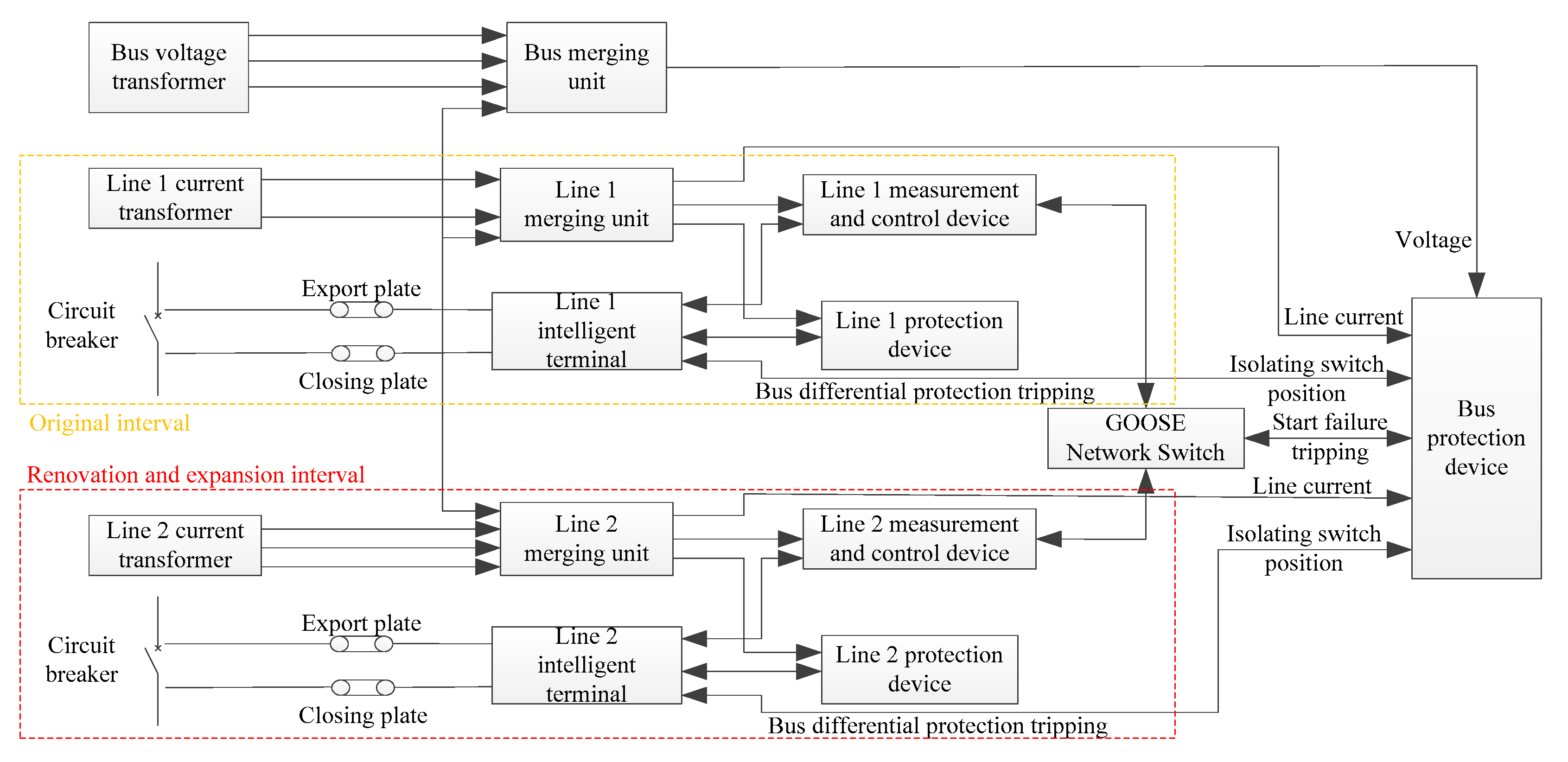
Figure 1. Logic structure diagram of newly renovated and expanded bay and busbar protection circuit.
Processes 13 03273 g001
Figure 2. Structure of SCD file decoupling based on bay.
Processes 13 03273 g002
Figure 3. Bay loop topology.
Processes 13 03273 g003
Figure 4. Configuration-file-checking method based on double CRC.
Processes 13 03273 g004
Figure 5. Flow chart of secondary loop bay change.
Processes 13 03273 g005
Figure 6. Virtual circuit information verification.
Processes 13 03273 g006
Figure 7. The primary wiring diagram of a 220 kV intelligent substation in Heilongjiang Province.
Processes 13 03273 g007
Table 1. Bay CRC calculation value.
Before ExpansionAfter ExpansionCRC Value Before ExpansionCRC Value After ExpansionConsistency
Send the CRCSend the CRC2FFFCA7B2FFFCA7BYes
/ML2209AMUSV01 4045: no. 2 main transformer high voltage side 2502 cell A merger/6487E627No
/PT2202APIGO 1150.2 main transformer in the first set of protection/16E9687ENo
/IE2209ARPIT_ 155.2 main transformer high voltage side 2502 intelligent terminal A/8DC52EB6No
1056.220kV 2510 bus coupler IE2201ARPIT intelligent terminal A1056.220 kV 2510 bus coupler IE2201ARPIT intelligent terminal ADECD3946DECD3946Yes
IL2202ARPIT_101B: 2 days crossing the line 2L79 intelligent terminal AIL2202ARPIT_101B: 2 days crossing the line 2L79 intelligent terminal A7E87E5C27E87E5C2Yes
IL2204ARPIT_1043: professional 2L81 line intelligent terminal 2 A dayIL2204ARPIT_1043: professional 2L81 line intelligent terminal 2
A day
1D6346571D634657Yes
ML2201AMUSV01:4001 days crossing the line 2L80 cell A mergerML2201AMUSV01:4001 days crossing the line 2L80 cell A merger1768B05F1768B05FYes
ML2203AMUSV01_4009:2 days professional 2L82 line cell A mergerML2203AMUSV01_4009:2 days professional 2L82 line cell A merger3A63EF8B3A63EF8BYes
MM2205AMUSV 4015:220 kV bus bar cell A mergerMM2205AMUSV 4015:220 kV bus bar cell A merger6E6347396E634739Yes
PE2201APIGO_1054:220 kV bus coupler 2510 first set of protectionPE2201APIGO_1054:220 kV bus coupler 2510 first set of protection4A8045264A804526Yes
1005: days PL2201APIGO 2L80 line crossing the first set of protection1005: days PL2201APIGO 2L80 line crossing the first set of protection88A8C3A188A8C3A1Yes
Table 2. Different calculation results using different methods.
MethodTime/minAccuracy/%Change PositioningTraining Data
Bayesian network72.992.54MediumMedium
Sub-CRC78.698.96PoorNone
Decision tree algorithm//MediumHuge quantity
Convolutional neural network56.596.09mediumMedium
CRC dynamic verification42.698.46strongnone
Disclaimer/Publisher’s Note: The statements, opinions and data contained in all publications are solely those of the individual author(s) and contributor(s) and not of MDPI and/or the editor(s). MDPI and/or the editor(s) disclaim responsibility for any injury to people or property resulting from any ideas, methods, instructions or products referred to in the content.