2. Materials and Methods
The foundation of numerical analysis lies in a trio of geometric bodies derived from the principles of TPMS (see
Figure 1). In the initial step, a gyroid surface was generated based on Equation (1) [
20], which served as the basis for all subsequent geometric operations performed during the creation of the three-dimensional bodies. The fundamental unit cell coordinates in the XY, XZ, and YZ planes were π × π × π. A detailed description of the process for creating the base geometry is provided in [
21].
In the subsequent step towards achieving the final shape, volumetric bodies were derived from the two-dimensional gyroid surface. These included the sheet gyroid, composed of a unit cell with coordinates 2π × 2π × 2π, a wall thickness of 0.5 mm, and overall dimensions of 20 × 20 × 20 mm, and the skeletal gyroid, based on a unit cell of π × π × π, filling a volume of 20 × 20 × 20 mm. These volumetric bodies were subsequently replicated along the x-axis to create the final geometries with dimensions of 20 × 20 × 80 mm (width × height × length).
The heat exchange surface area for the sheet gyroid is 19,045.54 mm2, for the combined gyroid it is 10,412.72 m2, and for the skeletal gyroid it is 9068.49 mm2. The compactness values, i.e., the surface area to volume ratio, are as follows: for the sheet gyroid, it is 0.595 mm2/mm3; for the combined gyroid, it is 0.325 mm2/mm3; and for the skeletal gyroid, it is 0.283 mm2/mm3.
The geometry proposed by the authors, designed to mitigate the negative effects of increased pressure loss and friction factor, utilises a combination of these two structures. Boolean operations were employed to achieve the final form, whereby the skeletal gyroid volume was subtracted from the sheet gyroid volume. This resulted in a hybrid geometry combining two structural types: one with a high density of small pores and the other with a lower density of larger pores. The interconnected pores in the resultant geometry form channels that facilitate fluid flow through the structure.
The basic sheet gyroid geometry is characterised by uniform flow, predominantly laminar in nature, and by the separation of flow into two non-intersecting groups of channels. In contrast, the skeletal gyroid exhibits a higher material volume and increased turbulence, evident in the larger cross-sectional channels. The hybrid structure designed by the authors leverages a combination of these features to minimise pressure loss and friction factor while ensuring efficient heat exchange between the gyroid material and the flowing medium.
Numerical simulations were conducted using Solidworks Flow Simulation 2018 software, employing a steady-state study with the k-ε viscosity model.
The preference for the k-ε model for solving the numerical simulations presented in this article was based on several assumptions. The first is the robustness and universality of this model across a broader range of Reynolds numbers, as well as a wider range of possible turbulent manifestations in the flowing medium. The second assumption is the dramatic reduction in computational demands and, therefore, the required time compared to the use of the SST k-ω model. However, we acknowledge that the k-ε model may overestimate heat transfer in the low Reynolds number regime due to its inherent assumptions regarding turbulent viscosity. For this range of Reynolds numbers, the SST k-ω model could be more accurate, as it better accounts for the flow properties in viscous sublayers, thus providing more precise results for thermal-hydraulic simulations under low-turbulence conditions. Nevertheless, we believe that the assessed boundary conditions and related characteristics allow for the use of the k-ε model. This study primarily focuses on comparing geometric configurations and their thermal characteristics, with the model selection justified by its widespread acceptance in numerical analyses of TPMS geometric structures in the existing literature [
16,
22,
23,
24].
The presented numerical study utilised commercially available software that provides a balanced set of tools for CAD modelling, physical simulations, and subsequent result integration into the additive manufacturing process. During the numerical analysis, no user-defined functions or custom code modifications to the solution methods were applied. The solution framework was based on the finite volume method, with convergence criteria set to 10
−6. In the domain of fluid flow, fundamental mathematical approaches were employed, grounded in the system of Navier–Stokes equations, which encapsulate the conservation laws of mass, momentum, and energy [
24].
where
u is the fluid velocity, ρ is the density,
Si represents body forces distributed through the medium (e.g., gravity or rotational forces),
H = h+ u2/2 is the total enthalpy,
h is the specific enthalpy,
QH is the heat source per unit volume,
τij is the viscous stress tensor,
τijR is the Reynolds stress tensor, and
qi represents the diffusive heat flux. The indices denote summation over the three coordinate directions. Heat transfer in solids and fluids, along with the energy exchange between them (conjugate heat transfer), is a fundamental and implicit component of Solidworks Flow Simulation 2018 software. The phenomenon of heat conduction in solid media is described by the following equation [
24]:
where
e represents specific internal energy,
λ is the thermal conductivity tensor, and
QH is the specific rate of heat release (or absorption) per unit volume. A more detailed description can be found in the technical documentation provided [
25].
The purpose of the numerical analysis was to compare the three geometries in the context of the heat exchange process. This was simulated using a plate with a thickness of 0.5 mm, which complemented the TPMS structures. A constant temperature of 100 °C was applied to the surface of the plate (see
Figure 2).
Channels 80 mm in length were created before and after the TPMS structure to stabilise and fully develop the flow. Air was used as the heat transfer medium, and five scenarios were considered, distinguished by different volumetric flow rates of 0.4, 0.8, 1.2, 1.6, and 2.0 m3/h. The compared geometries were modelled or represented in the numerical simulations using an aluminium alloy, specifically aluminium 6061, which has a density of 2700 kg/m3, a thermal conductivity of 152 W/(m·K), and a heat capacity of 897 J/(kg·K).
The outer walls of the channels were defined as adiabatic with a no-slip condition. In this study, the adiabatic wall condition was intentionally chosen to isolate the effect of heat transfer within the designed TPMS structures and to prevent interactions with lateral boundaries. The primary objective was to evaluate the internal heat transfer and flow characteristics of the TPMS structures without external influence. Adiabatic walls ensure that no heat exchange occurs at the lateral boundaries, allowing us to focus exclusively on the thermal-hydraulic performance of the TPMS structures. The use of symmetric or periodic boundary conditions could introduce unrealistic assumptions about flow development, particularly for geometries such as the combined gyroid, where flow and thermal fields are significantly heterogeneous and exhibit a high degree of mixing.
Based on these boundary conditions, a three-dimensional model was created and adapted into a computational mesh prior to the numerical simulation. Solidworks Flow Simulations 2018 software employs a unique approach to mesh generation based on an immersed body mesh method. This technique generates a mesh independently of the model geometry, allowing mesh cells to intersect the boundary between solid and fluid regions. This facilitates the implementation of a Cartesian grid consisting of cuboidal (or rectangular) cells aligned with Cartesian coordinates and adjacent to the external boundaries of the computational domain. The mesh cells are classified as solid, fluid, or partial (those intersecting the boundary between solid and fluid regions). For partial cells, a two-stage wall function is applied, combining two methods depending on the thickness of the boundary layer. This approach enables the resolution of the Navier–Stokes equations within volumes defined by the mesh.
From the perspective of validating the numerical analysis results, a key step was the grid independence study, which examined the relationship between the number of generated mesh elements and the monitored control parameter’s value. In this study, the temperature of the heat transfer medium at the outlet of the computational domain was observed over the surface defined as the pressure outlet, and the area-weighted average was evaluated for a volumetric flow rate of 1.2 m
3/h. The results of the grid independence study are presented in
Figure 3. Six variants of input parameters influencing the final cell size and cell distribution were utilised in the mesh generation process. The study demonstrated that convergence of the values was achieved from the fourth variant of the mesh generation, which was used for subsequent comprehensive numerical analyses, thereby reducing the computational time required for simulations.
The sheet gyroid, skeletal gyroid, and combined gyroid TPMS structures proposed by the authors were compared based on numerical parameters. The comparison utilised both two-dimensional visualisations of parameters, such as flow velocity and temperature distribution in different parts of the model, as well as three-dimensional visualisations of flow trajectories. The hydraulic parameters were evaluated in terms of the Reynolds number, friction factor, and pressure drop. The Reynolds number is defined as follows [
25,
26].
where
ρ is density,
Dh is hydraulic diameter,
u is superficial fluid velocity,
μ is dynamic viscosity, and
εP is porosity. Porosity is described as the proportion of the void volume to the total bulk volume of the structure. The hydraulic diameter (
Dh) can be determined using various formulas linking the channel’s cross-sectional area and its wetted perimeter. However, for porous structures, such as the gyroid structure discussed here, it is more effective to calculate
Dh using the void volume (
Vvoid) and the specific surface area (
As). The
Dh parameter can then be defined as follows [
27].
The last monitored parameter is the Fanning friction factor (
f), which characterises the dimensionless pressure loss or flow resistance in the channels of the gyroid structure and which is defined according to Equation (4) [
9].
where Δ
p is the pressure loss; specifically, it refers to the pressure difference of the flowing medium between the inlet and outlet of the model. Here,
εP denotes the porosity,
Dh represents the hydraulic diameter,
L is the length of the TPMS structure,
ρ indicates the density of the medium, and
u is the superficial fluid velocity.
The thermal-technical properties of the evaluated TPMS structures were assessed by monitoring the temperature of the flowing medium at the inlet and outlet surfaces. These values were subsequently used to calculate the heat transfer coefficient, the Nusselt number, and the Chilton–Colburn j-factor. The convective heat transfer coefficient, which represents the rate of heat transfer via convection relative to conduction within the fluid, is defined as follows [
3]:
where
ρ is the density,
U is the velocity of the medium flow through the inlet surface,
A′ is the channel cross-sectional area,
C represents the specific heat capacity,
Tout is the temperature of the medium at the outlet of the model,
Tin is the temperature of the medium at the inlet of the model,
A″ is the surface area with a defined temperature of 100 °C, and Δ
TLMTD is the logarithmic mean temperature difference, calculated as follows:
The Nusselt number, which represents the ratio of convective to conductive heat transfer and thus indicates the overall efficiency of convective heat transfer relative to conduction within the flowing medium, is determined using the following equation [
28]:
where
h is the convective heat transfer coefficient,
Dh is the hydraulic diameter, and
λ is the thermal conductivity of the medium. Finally, the efficiency of the heat exchange process was evaluated using the Chilton–Colburn j-factor, as defined by Equation (12):
where
Nu is the Nusselt number,
Re is the Reynolds number, and
Pr is the Prandtl number determined according to [
29].
The selected results of the presented numerical analysis were validated against the results calculated using the ɛ-NTU method, where the heat transfer coefficient was compared based on the following equations:
where
ε is the effectiveness of the heat exchange process,
NTU is the number of transfer units, and
Cmin is the minimum heat capacity rate, equal to the product of the mass flow rate and the specific heat capacity.
3. Results
The core concept of this study is the development of a geometry through the combination of existing TPMS structures to mitigate the negative effects of porous TPMS geometries on the hydraulic characteristics of the flowing medium while maintaining the performance metrics of the heat exchange process. In the basic sheet gyroid geometry, a homogeneous distribution of pores and resulting channels is evident. In contrast, the skeletal gyroid is characterised by a massive flow channel (relative to the overall geometry) and a substantial volume of solid material forming the three-dimensional structure. This distinction is visible in
Figure 4, which illustrates the velocity maps of the heat transfer medium as it flows through the porous structures of the compared geometries. The sections are taken transversely at distances of 0, 11.5, 23, 34.5, 46, 57.5, 69, and 80 mm along the flow axis, starting from the edge of the model for a volumetric flow rate of 1.2 m
3/h.
The sheet gyroid geometry displays a homogeneous velocity distribution without significant variations in the different section views or throughout the entire geometry length. This uniformity results from the steady flow in the porous structure, which does not induce notable changes in turbulent kinetic energy values. In stark contrast, the skeletal gyroid geometry exhibits a markedly heterogeneous velocity distribution in the section views. The heat transfer medium flows through a single channel, with velocity increases corresponding to changes in the channel’s cross-sectional area. The highest velocities occur in regions where the channel narrows, consistent with the continuity equation.
The proposed combined geometry demonstrates a mix of the characteristics described. Certain regions show higher velocity values, while others display more uniform flow and lower velocities, leading to enhanced mixing of the flowing medium. This behaviour arises from a combination of regions with larger channels and areas with lower porosity. The design effectively utilises these contrasting features to achieve improved mixing and flow uniformity, while leveraging the strengths of both larger and smaller channel regions.
This phenomenon is particularly evident when examining the cross-sectional view of the channels at the outlet of the TPMS structure. At this point, where the gyroid structure is no longer present in the channel cross-section, it influences the flow trajectories only indirectly. In
Figure 5, regions with maximum flow velocity and the distribution of streamlines are clearly visible, indicating the formation of turbulent zones associated with local maxima. These zones are concentrated in areas adjacent to regions with lower porosity or larger channel cross-sections.
A comprehensive overview of the flow characteristics is provided in
Figure 6, which depicts a longitudinal section through the model at half its width. This visualisation also highlights flow velocity and streamlines. From this perspective, the change in flow characteristics for the combined geometry is even more apparent. Uniform streamline distribution and the absence of vortex regions, compared to the skeletal gyroid, are evident. When comparing the combined geometry to the basic sheet gyroid, there is no noticeable decrease in flow velocity or distortion of flow trajectories in the vertical direction. This can be attributed to the openness of the lower part of the combined geometry to the heat transfer medium flow and the lack of a uniform TPMS structure in the form of interconnected channels, as seen in the basic sheet gyroid geometry.
When examining the flow trajectories and temperature distribution throughout the entire volume of the evaluated geometry (see
Figure 7 and
Figure 8)—excluding the inlet and outlet channels—the disadvantage of uniform flow in the sheet gyroid geometry becomes distinctly apparent. In this case, the segregation of channels, or heat transfer medium flow, into two groups is evident. In one group, a more pronounced thermal flux occurs from the TPMS body to the heat transfer medium. This segregation arises from the fundamental design of the gyroid geometry, which, based on the basic 2π × 2π × 2π unit cell, divides the resulting space into two curved surfaces forming walls of a disconnected channel network. These channels are not in identical contact with the surface, transferring thermal flux to the TPMS structure. Consequently, this phenomenon leads to a gradual and slow equalisation of temperatures within the channels, dependent on the flow trajectory length or the length of the heat exchange element.
In contrast, the combined geometry demonstrates a relatively uniform temperature distribution across the entire cross-section and within individual channels. The modifications made ensure interconnectivity between the channels, resulting in enhanced mixing and homogenisation of the temperature throughout the flow volume of the geometry.
The results of the numerical analysis were processed not only through the presented visualisations but also using Equations (6) to (12), enabling the quantification of the resulting parameters into two categories: hydraulic characteristics, which address the qualitative properties of the fluid flow, and thermal characteristics, which quantify the heat exchange process between the heat transfer medium and the TPMS structure.
The heat transfer coefficient is a key parameter in the design and optimisation of heat exchangers, as it directly determines the efficiency of heat transfer between two environments. Accurate determination and optimisation of this coefficient significantly influence the overall performance and efficiency of the device. Precise knowledge of the heat transfer coefficient allows for calculations, such as determining the required surface area of the exchanger to achieve the desired heat transfer rate.
Figure 9 (left) depicts this parameter as a function of volumetric flow rate, ranging from 0.4 to 2.0 m
3/h.
The results show that the combined gyroid geometry achieves the highest heat transfer coefficient values, reaching 362.17 W/(m2·K) at a flow rate of 2.0 m3/h, demonstrating superior heat transfer efficiency across all examined flow rates. The skeletal gyroid exhibits intermediate heat transfer coefficient values, peaking at 295.74 W/(m2·K) for the same flow rate. While it performs significantly better than the sheet gyroid, it still falls short of the combined gyroid. Conversely, the sheet gyroid has the lowest heat transfer coefficient at 230.55 W/(m2·K) for a flow rate of 2.0 m3/h, indicating lower efficiency in heat transfer compared to the other two geometries.
At the opposite end of the flow rate spectrum, defined by low volumetric flow rates (minimum 0.4 m3/h in this comparison), the heat transfer coefficient values are 63.38 W/(m2·K) for the sheet gyroid, 149.69 W/(m2·K) for the skeletal gyroid, and 188.57 W/(m2·K) for the combined gyroid. This comparison reveals that at no flow rate does the heat transfer coefficient of the combined gyroid decrease significantly, demonstrating its ability to maintain heat exchange efficiency consistently.
The observed trend of increasing heat transfer coefficient with rising volumetric flow rate is evident for all geometries. This indicates that higher flow rates lead to improved thermal performance, highlighting the importance of selecting an appropriate flow rate for optimising heat exchange in the system. In the context of heat exchanger applications, the combined gyroid geometry is the most suitable for scenarios requiring maximum heat transfer, such as compact heat exchangers with high thermal loads.
The results presented in
Figure 9 (right) fully support the previously stated conclusions regarding the performance of the examined geometries in heat exchangers. The Nusselt number serves as an indicator of heat transfer efficiency, with higher values corresponding to better thermal performance. The combined gyroid achieves the highest Nusselt number across all Reynolds number ranges, demonstrating its superior thermal performance. This finding aligns with earlier conclusions about the highest heat transfer coefficient values for this geometry.
The skeletal gyroid exhibits intermediate Nusselt number values, confirming it as a compromise between performance and other factors, such as pressure drop and manufacturing complexity. In contrast, the sheet gyroid shows the lowest Nusselt number values, consistent with its lower heat transfer coefficient and reduced heat transfer efficiency. Additionally, the graph indicates that the Nusselt number increases with rising Reynolds numbers for all geometries, a generally expected trend where higher flow rates improve heat transfer. The most pronounced increase is observed for the combined gyroid, further supporting its use in applications requiring maximum performance.
Due to differences in the hydraulic diameter (Dh) among the geometries, a direct comparison at identical Reynolds number ranges is not feasible. At the same volumetric flow rate, each geometry achieves a different Reynolds number. But, for instance, at a Reynolds number of approximately 250, the sheet gyroid achieves around 25 NTU, the skeletal gyroid 44 NTU, and the combined gyroid about 88 NTU.
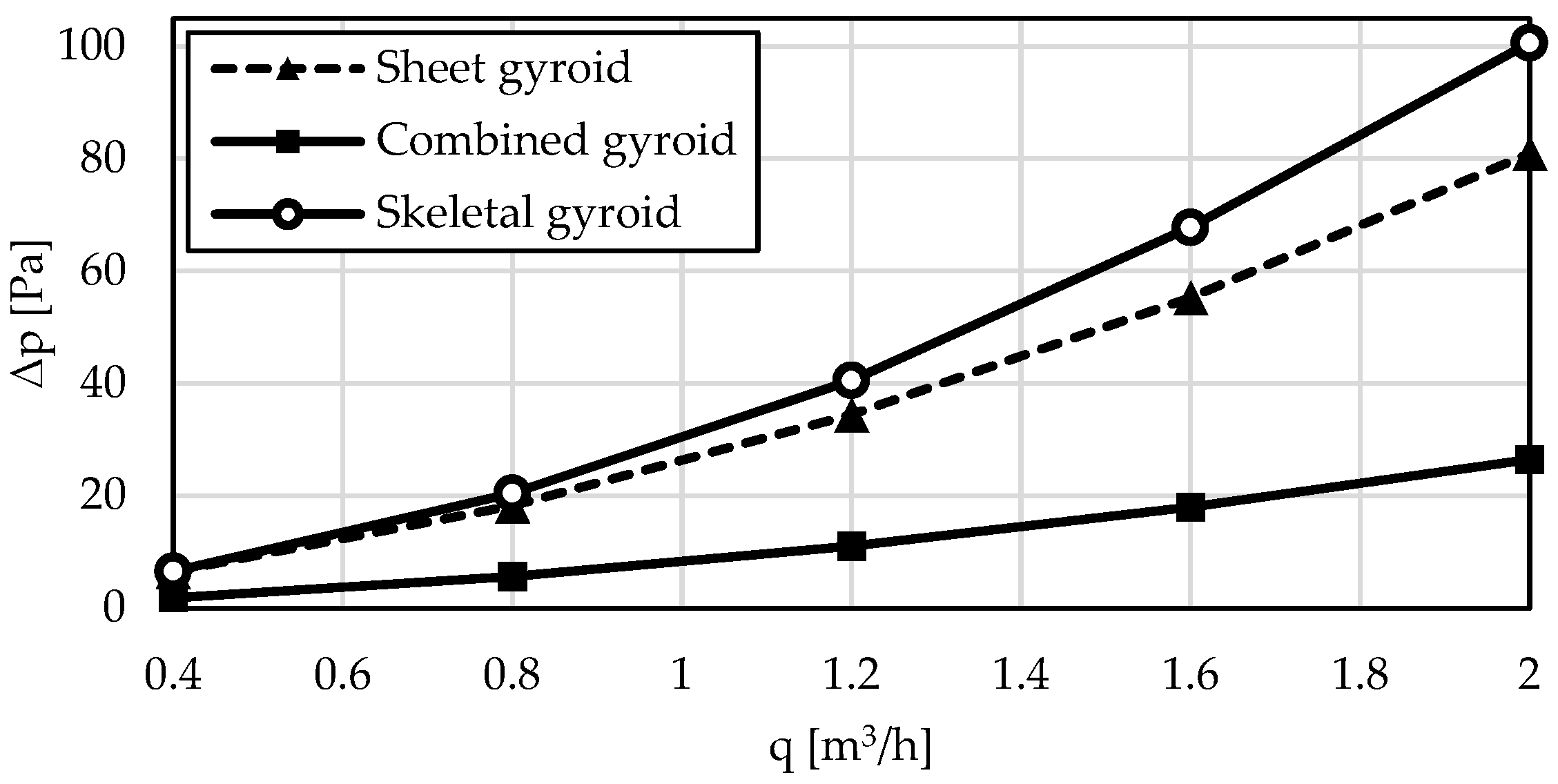
In terms of hydraulic parameters, pressure drop is a significant metric, reflecting the structure’s permeability to the flowing medium and the efficiency of fluid transport through the porous material.
Figure 10 shows the pressure drop as a function of volumetric flow rate, highlighting its strong dependence on geometry and the expected increase with higher flow rates. The combined gyroid exhibits the lowest pressure drops across all volumetric flow rates, underscoring its advantage in hydraulic performance. This makes it particularly suitable for applications requiring a balance between high thermal performance (as confirmed by the highest heat transfer coefficient and Nusselt number) and minimal pressure loss.
Conversely, the skeletal gyroid shows the highest pressure drops at the given flow rates, suggesting that its use may be less favourable for applications sensitive to energy losses caused by flow resistance. Despite its intermediate thermal performance, the high-pressure drop could limit its practicality, especially at higher flow rates. The sheet gyroid achieves pressure drops between those of the combined and skeletal gyroids. This result, combined with its lower heat transfer efficiency, as indicated by its lower heat transfer coefficient and Nusselt number, suggests that its application might be restricted to situations where heat transfer demands are less critical, but pressure losses must remain within acceptable limits.
At a maximum volumetric flow rate of 2.0 m3/h, the pressure drop for the combined gyroid is one-third that of the sheet gyroid and nearly one-fourth that of the skeletal gyroid. A similar trend is observed at the minimum flow rate of 0.4 m3/h, where the pressure drop for the combined gyroid is 1.86 Pa, compared to 6.4 Pa for the sheet gyroid and 7.23 Pa for the skeletal gyroid. Overall, the comparison confirms that the combined gyroid offers the best optimisation of heat transfer and pressure drop. This geometry is ideal for heat exchangers requiring high efficiency with minimal energy costs associated with overcoming flow resistance.
The graphs in
Figure 11 illustrate a comparison of the heat transfer coefficient values calculated based on the outputs of the presented CFD simulations with the values of this coefficient determined using the ε-NTU method, which evaluates the heat transfer performance of the heat exchanger element by employing the mathematical framework represented by Equations (13) and (14).
The differences in the heat transfer coefficient, obtained from CFD analysis and the ε-NTU method, vary depending on the type of TPMS geometry. For the sheet gyroid, the largest differences were observed, with h-values derived from the ε-NTU method being consistently higher than the CFD results. At a flow rate of q = 2.0 m3/h, the difference reaches up to 50 W/(m2·K), which can be attributed to the simplified assumptions of the ε-NTU method, which do not account for detailed flow behaviour and boundary effects. In the case of the combined gyroid, these differences are more moderate, with the ε-NTU method still providing higher values; however, the discrepancies do not exceed 40 W/(m2·K). This suggests that the more complex structure of the combined gyroid facilitates efficient heat transfer, which is better represented in CFD simulations. For the skeletal gyroid, the differences between the two methods are the smallest; the maximum difference at higher flow rates is approximately 30 W/(m2·K). The accuracy of the results obtained from CFD analysis, compared to the ε-NTU method, can be assessed based on the differences between these two approaches for each TPMS geometry. Given that the ε-NTU method is a theoretical approach that operates under simplified assumptions of uniform heat distribution and ideal flow, it can serve as a reference point for verifying CFD results.
For the sheet gyroid, CFD values were consistently lower than the epsilon-NTU results, with discrepancies increasing at higher flow rates. This difference may indicate that CFD analysis more realistically accounts for the presence of local resistances, turbulent flow, and thermal losses, which are neglected in the ε-NTU method. In the case of the combined gyroid, the discrepancy between the two methods is smaller, indicating good accuracy of the CFD results, with minor deviations likely related to the structural properties of the geometry that support efficient heat transfer. Here, the differences reach approximately 10–15% at higher flow rates, confirming that CFD provides reliable results with respect to physical effects. For the skeletal gyroid, the CFD results are closest to the values obtained from the ε-NTU method, with discrepancies in the range of 5–10%. This agreement indicates that the skeletal gyroid geometry has homogeneous thermal and flow properties, which are well captured in CFD analysis. The smaller deviation confirms the high accuracy of CFD simulations for this geometry.
Based on these findings, it can be concluded that CFD analysis provides more realistic and accurate results, as it considers complex physical phenomena, such as turbulent flow, pressure losses, and boundary effects, which the ε-NTU method, in its simplified approach, does not capture. However, the differences between the methods highlight that the accuracy of CFD results can be influenced by the specific geometry and its ability to ensure uniform flow and heat transfer.
The comparison of the three geometries in terms of their potential applicability as heat exchangers, shown in
Figure 12, provides a comprehensive perspective on heat transfer dynamics, temperature distribution uniformity, and the effectiveness of eliminating thermally stagnant zones. Each geometry exhibits unique characteristics that define its suitability for various applications.
The sheet gyroid geometry is distinguished by the uniform distribution of the flowing medium across the cross-sectional area, particularly in the middle and final sections of the system. By the midpoint of the heat exchanger, the medium’s temperature approaches equilibrium, with temperature differences across cross-sections gradually diminishing. This indicates high heat transfer efficiency and the absence of significant thermal gradients, which minimise the risk of thermally stressed regions. However, relatively low thermal gradients are observed at the system’s inlet, suggesting a slower onset of medium heating. Consequently, this geometry is optimal for applications requiring uniform heating of the medium without significant temperature fluctuations, especially when the time to reach thermal equilibrium is not critical.
In contrast, the skeletal gyroid geometry demonstrates intense thermal gradients in the initial sections, highlighting efficient heat transfer at the start of the system. The heat exchange surfaces interact rapidly with the medium, promoting faster heating. However, this effect is accompanied by substantial local temperature variations, particularly in the middle sections of the heat exchanger, where stagnant zones with uneven heating may form. While the medium achieves high temperatures by the system’s end, the distribution is less uniform compared to the sheet gyroid. This geometry is better suited for applications where rapid heat transfer over short distances is crucial, but is less ideal for scenarios requiring uniform temperature distribution. The combined gyroid geometry exhibits the most complex behaviour, significantly influenced by flow dynamics. It combines the features of both the sheet and skeletal gyroids, achieving a balance between rapid heating and temperature uniformity. Early sections show moderate thermal gradients, indicative of effective initial heat transfer. In the middle and final sections, the interconnected channel network facilitates mixing and homogenisation, reducing stagnant zones and enhancing uniformity. This makes the combined geometry highly versatile and suitable for applications demanding a balance between efficient heat transfer, rapid heating, and uniform temperature distribution.
In the initial stages of the system, intense thermal gradients form due to the interaction of the medium with the uneven geometric profile. In the middle section of the heat exchanger, significant temperature differences are observed, with the flow dynamics promoting mixing and eliminating stagnant zones. At the system’s end, the medium reaches high temperatures with a relatively uniform distribution. However, local temperature extremes suggest that geometry may facilitate the formation of thermally stressed regions in areas of increased turbulence.
A notable feature is the openness of the porous structure at the bottom, where the flowing medium directly contacts the surface, delivering heat flux. This design ensures the maximum extraction of thermal energy from this surface and the effective transfer of the thermal gradient to other parts of the structure. This geometry is ideal for applications prioritising enhanced mixing, dynamic heat transfer, and the minimisation of stagnant zones, although it may require a longer path to achieve thermal equilibrium.
From a broader perspective, sheet gyroid geometry is most suitable for applications requiring uniform heating and high temperature field homogeneity. The skeletal gyroid geometry is preferred for scenarios demanding rapid heat transfer over short distances, albeit with reduced temperature homogeneity. The combined gyroid geometry is best suited for processes requiring intensive medium mixing, delivering high heat exchange efficiency over longer distances.
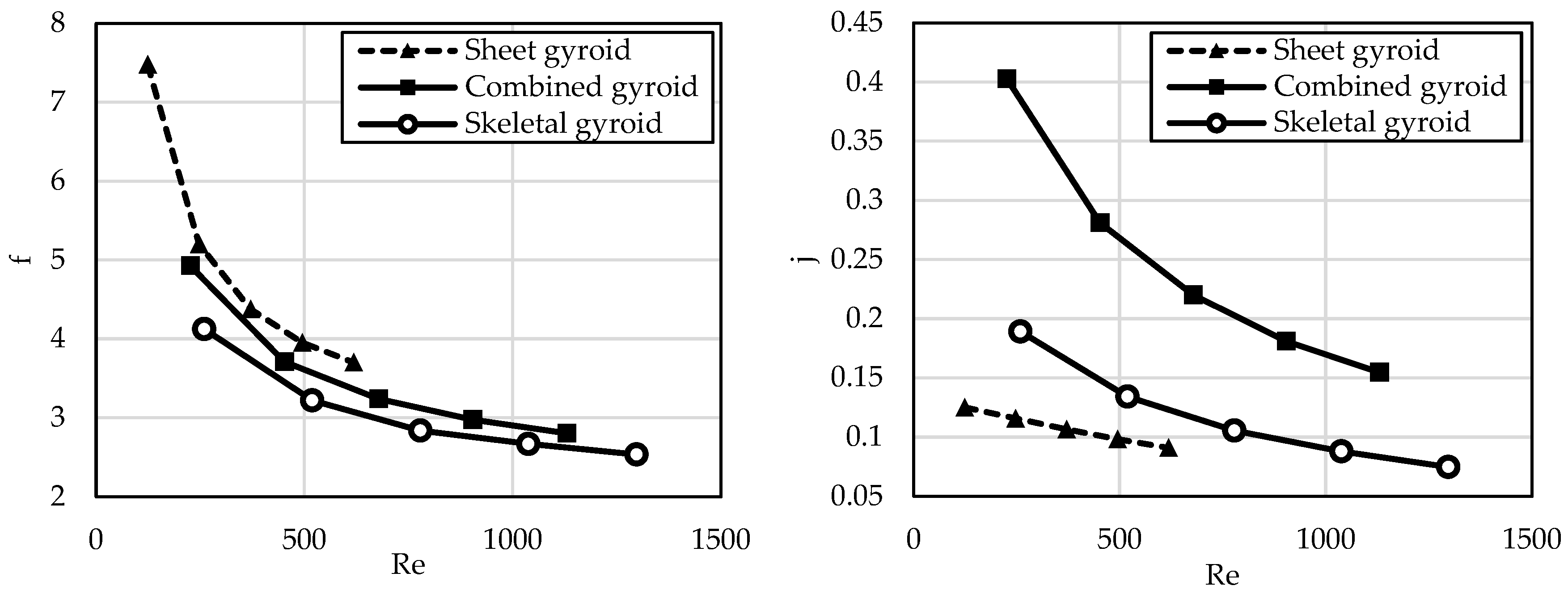
Another parameter examined was the friction factor, a dimensionless measure characterising fluid flow through porous materials, including triply periodic minimal surface (TPMS) structures. This factor quantifies pressure losses caused by friction due to interactions between the fluid and the surface of the structure during flow. It is expressed as the ratio of wall shear stress to the dynamic pressure of the flow, with its value dependent on the flow regime (laminar or turbulent) and the geometry of the structure.
For TPMS structures, which are characterised by periodic and highly porous designs, the friction factor provides insights into hydraulic efficiency and flow distribution within the system. These structures possess complex morphologies that allow for efficient fluid and heat transfer, but can also generate pressure losses. A high friction factor indicates significant pressure losses, often resulting from intense friction or turbulent flow. Conversely, a low value suggests reduced pressure losses, implying a more efficient flow with minimal resistance.
Figure 13 (left) illustrates the friction factor analysis as a function of the Reynolds number. The graph shows a decline in friction factor with increasing Reynolds numbers, a typical trend where pressure losses per unit of dynamic pressure decrease as the flow transitions from laminar to turbulent regimes. This shift results in changes in the interactions between the fluid and the structure’s surface.
The sheet gyroid exhibits the highest friction factor values across the entire Reynolds number range, exceeding a value of 7 at low Reynolds numbers. Its high surface area and intricate structure significantly impact fluid flow, leading to the largest pressure losses. These losses limit its applicability in scenarios where minimising energy costs for fluid flow is a priority. However, its extensive surface area may be advantageous for processes requiring intensive heat transfer.
The combined gyroid achieves intermediate friction factor values, lower than the sheet gyroid but higher than the skeletal gyroid. This geometry balances the properties of both structures, offering a compromise between hydraulic losses and effective heat transfer. It is suitable for applications where a balance between pressure losses and heat exchanger efficiency is needed.
The skeletal gyroid has the lowest friction factor values, approaching 1 at high Reynolds numbers. This geometry generates the least pressure losses, making it an ideal choice for applications prioritising reduced energy costs associated with fluid flow. However, its lower surface area may limit its capability for effective heat transfer compared to the other geometries. In summary, the choice of geometry depends on specific application requirements. While the sheet gyroid offers high heat transfer potential at the cost of higher-pressure losses, the skeletal gyroid provides low hydraulic losses but reduces heat transfer efficiency. The combined gyroid presents a balanced option that is suitable for applications needing efficient heat transfer with moderate pressure losses.
The final parameter used to quantify the suitability of the TPMS structures evaluated in this comparison was the Chilton–Colburn j-factor. This is a dimensionless quantity utilised to characterise heat transfer in a flowing medium, integrating the properties of flow, geometry, and heat exchange [
30]. For triply periodic minimal surface (TPMS) structures, which are frequently employed in modern heat exchangers, the Chilton–Colburn j-factor provides valuable insights into the efficiency of heat transfer relative to pressure drop and turbulent flow.
A high value of the Chilton–Colburn j-factor indicates that the TPMS structure achieves high heat transfer efficiency with relatively low energy losses caused by pressure resistance. This typically represents an optimal combination of surface area and turbulence generated by the structure, facilitating intense heat exchange between media. Such structures are preferred in applications requiring high thermal efficiency while maintaining a compact design. Conversely, a low Chilton–Colburn j-factor signals less effective heat transfer. This may result from a suboptimal TPMS geometry that fails to induce sufficient turbulence or create an adequately large heat exchange surface. Consequently, this could lead to reduced system performance, higher operational costs, and diminished overall structural efficiency.
The graph in
Figure 13 (right) shows that Chilton–Colburn j-factor values decrease with increasing Reynolds number across all geometries, which is expected behaviour since, at higher values, turbulent flow stabilises and the relative increase in heat transfer diminishes. However, this decline varies between geometries, highlighting their differing capabilities to facilitate intense heat transfer.
The combined gyroid exhibits the highest Chilton–Colburn j-factor values across the entire Reynolds number range, indicating that it is the most effective in terms of heat transfer. This geometry likely benefits from an advantageous combination of surface area and fluid flow dynamics, enabling intense heat exchange. Consequently, the combined gyroid is suitable for applications where high heat transfer efficiency is essential, such as in compact heat exchangers or high-performance cooling systems.
The skeletal gyroid achieves intermediate Chilton–Colburn j-factor values, which are lower than those of the combined gyroid but higher than those of the sheet gyroid. This geometry offers a balance between heat transfer efficiency and pressure drop, still providing sufficient performance for engineering applications where both factors are important.
The sheet gyroid has the lowest Chilton–Colburn j-factor values across the entire Reynolds number range, indicating its reduced ability to transfer heat. This may result from less effective surface interaction with the fluid or unfavourable flow characteristics. While this geometry holds the potential for processes requiring large surface areas, its lower Chilton–Colburn j-factor may limit its applicability in heat transfer-critical applications.
In conclusion, the selection of TPMS geometry should be based on the specific requirements of the application. The combined gyroid offers the best performance for efficient heat transfer, while the skeletal gyroid may be suitable for applications with compromise requirements. Conversely, the sheet gyroid appears to be a less suitable option for processes where heat transfer performance is crucial, although it may be attractive in applications with other priorities.
The relationship between the friction factor and the Chilton–Colburn j-factor for the evaluated TPMS geometries—sheet gyroid, combined gyroid, and skeletal gyroid—reveals critical trade-offs between pressure losses and heat transfer. These factors are key performance indicators for structures in applications such as heat exchangers, where assessing their interdependence enables efficient design optimisation.
The graphs indicate that both factors decrease with increasing Reynolds numbers, suggesting that at higher Reynolds numbers, turbulent flow stabilises, leading to reduced relative pressure losses and heat transfer. However, this decrease is not uniform across the different geometries, reflecting their varying performance characteristics.
The sheet gyroid exhibits the highest friction factor values, corresponding to the largest pressure losses, while its Chilton–Colburn j-factor is the lowest among the evaluated geometries. This imbalance highlights the inefficiency of this geometry for heat transfer, as the high-pressure losses are not offset by sufficient heat transfer intensity. Such characteristics limit the sheet gyroid’s applicability in scenarios where low energy consumption is a key requirement while ensuring adequate heat transfer. However, its extensive surface area may make it advantageous for processes focusing on other objectives, such as chemical reactions or filtration.
The combined gyroid achieves the highest Chilton–Colburn j-factor values, indicating the most efficient heat transfer, while maintaining moderate friction factor values. This balance between pressure losses and heat transfer makes the combined gyroid universally suitable for applications requiring intense heat exchange at acceptable pressure losses. Its combination of large surface area and efficient flow dynamics makes it ideal for high-performance heat exchangers, where energy efficiency and high output are essential.
The skeletal gyroid has the lowest friction factor values, reflecting the smallest pressure losses, while its Chilton–Colburn j-factor is moderate. This geometry offers a compromise solution, minimising pressure losses while maintaining an acceptable level of heat transfer efficiency. These characteristics make it ideal for applications where pressure losses are the primary limiting factor, such as systems with low differential pressure or those prioritising energy savings.
The relationship between these factors highlights the necessity of trade-offs when optimising TPMS geometries. While a high Chilton–Colburn j-factor is desirable for efficient heat transfer, it is accompanied by an increased friction factor, leading to higher pressure losses. In applications where reducing pressure losses is a priority, geometries with a low friction factor are preferred, even though this may result in limited heat transfer performance. Conversely, geometries with a high Chilton–Colburn j-factor, such as the combined gyroid, are suitable for applications requiring maximum thermal performance. Therefore, the choice of geometry must consider the specific requirements of the application, whether it involves minimising energy costs or maximising thermal efficiency.
Despite the numerical analysis results indicating the advantages of the proposed combined gyroid geometry for systems with specific heat exchange parameters, the ultimate determinant is the manufacturability of the structure using available technologies. In the current state of technological development, the only viable method is the use of additive manufacturing techniques. These include fused filament fabrication/fused deposition modelling (FFF/FDM) with thermally conductive filaments [
31], or more suitable methods such as SLA (laser beam curing resin printing) [
32], SLS (laser sintering of powdered plastics) [
33], or powder bed fusion, including selective laser melting (SLM), direct metal laser sintering (DMLS), and electron beam melting (EBM) [
34,
35].
The sheet gyroid is characterised by prominent thin walls and regular openings, which pose a challenge for additive manufacturing, especially when using methods such as selective laser melting (SLM) or stereolithography (SLA). Thin walls can be fragile during printing, requiring precise control of process parameters, such as laser power, melting temperature, and support structures during production. Additionally, the combination of thin walls and a high surface area increases the risk of deformation, particularly when using metals. Despite these challenges, the production of this structure via 3D printing is technically demanding but advantageous in applications requiring high thermal efficiency.
The skeletal gyroid features a more robust structure with thicker elements, reducing the risk of deformation and improving its suitability for 3D printing. This geometry is easier to process, as it does not require the same high level of printing precision as the sheet gyroid. Furthermore, its design allows for better thermal treatment management and minimises internal stresses, which are essential for metal printing.
The combined gyroid, which merges elements of the sheet and skeletal gyroids, presents moderate demand for 3D printing. Its complex geometry requires advanced printing technologies capable of accurately reproducing structural details. Producing this structure may necessitate the use of support materials or additional post-processing steps, such as removing supports and performing thermal treatment.
Overall, the feasibility of manufacturing these structures via 3D printing depends on the chosen material and technology. Metal materials are suitable for all three geometries but require strict control of printing parameters and often involve complex post-processing. Polymeric materials may be easier to process; however, their lower thermal conductivity and strength could limit their applicability in high-performance applications.


