Article

Study on Length–Diameter Ratio of Axial–Radial Flux Hybrid Excitation Machine

1
School of Electrical Engineering, Shenyang University of Technology, Shenyang 110870, China
2
College of Electrical and Information Engineering, Zhengzhou University of Light Industry, Zhengzhou 450001, China
*
Author to whom correspondence should be addressed.
Processes 2024, 12(12), 2942; https://doi.org/10.3390/pr12122942
Submission received: 12 November 2024 / Revised: 2 December 2024 / Accepted: 6 December 2024 / Published: 23 December 2024
(This article belongs to the Section Manufacturing Processes and Systems)

Abstract

:
To improve the flux regulation range of the Axial–Radial Flux Hybrid Excitation Machine (ARFHEM) and the utilization rate of permanent magnets (PMs), the effects of different length–diameter ratios (LDRs) on the ARFHEM performance are studied. Firstly, the principle of the flux regulation of the ARFHEM is introduced by means of the structure and equivalent magnetic circuit method. Then, based on the principle of the bypass effect, the analytical formulas of LDRs, the number of pole-pairs, and the flux regulation ability are derived, and then the restrictive relationship between the air-gap magnetic field, LDR, and the number of pole-pairs is revealed. On this basis, the influence of an electric LDR on motor performance is studied. By comparing and analyzing the air-gap magnetic density and no-load back electromotive force (EMF) of motors with different LDRs, the variation in the magnetic flux regulation ability of motors with different LDRs is obtained and its influence mechanism is revealed. In addition, the torque regulation ability and loss of motors with different LDRs are compared and analyzed, and the influence mechanism of the LDR on torque and loss is determined. Finally, the above analysis is verified by experiments.

1. Introduction

Permanent magnet synchronous motors (PMSMs) have high torque density, high power density, and high efficiency, and they are widely used in various aspects of industrial production and life [1,2,3]. However, they also possess the disadvantages of unregulated air-gap magnetic fields and PM demagnetization, and the above problems are more prominent in high-temperature situations [4,5,6]. Electric excitation motors do not carry the risk of PM demagnetization, and they have a high-speed regulation range, which has great potential in relation to the above applications. However, a traditional electric excitation motor requires a brush and the permeability structure when the excitation current works, which involve problems such as brush consumption and risks being common, and its torque density and efficiency are lower than those of a PMSM [7,8,9].
In order to solve the above problems, some scholars have proposed the concept of a hybrid excitation motor (HEM), adding PMs in the electric excitation motor to improve the torque density, power density, and efficiency [10,11,12]. The HEM not only reduces the number of PMs but also solves the key problem that the air-gap field of the PMSM is not adjustable, and it improves the torque density and efficiency of the electric excitation motor. In recent years, researchers have proposed various HEM structures. According to the magnetic circuit structure, they can be divided into the series magnetic circuit type and parallel magnetic circuit type [13]. The structure principle of the series HEM is simpler, but compared with the parallel magnetic circuit HEM, the excitation current is larger, and it will lead to the irreversible risk of PM demagnetization [14,15].
The authors in [16] propose a motor structure with a reluctance rotor and a PM rotor in parallel, but at a low speed, the efficiency of the reluctance rotor is low, resulting in a low torque density. The authors of [17] study a parallel-type HEM, which is completely parallel-structured and does not carry the risk of PM demagnetization. Most of the parallel HEMs mentioned above contain additional exciters or brush slip rings, which have low integration and poor stability. A self-exciting synchronous motor is proposed in [18] that does not require a brush ring and additional excitation, but the excitation current is low at low speeds, and it is difficult to start. In [19], a new type of hybrid excited switched flux permanent magnet motor is proposed. Due to the inclusion of a short magnetic circuit, the motor has a wide flux regulation capacity and high torque output, but, at the same time, the loss is large. The stator of the HEM in [20] adopts an amorphous alloy material, and the rotor adopts the structure of alternating magnetic poles, which not only avoids the generation of slip rings and brushes but also greatly improves the efficiency of the motor. However, the manufacturing cost of the motor is high. Moreover, ref. [21] proposes a new partitioned stator hybrid excitation approach with an internal magnetic ring machine. The inner magnetic ring is designed to reduce the inside stator magnetic reluctance so that the working magnetic field harmonics can be improved, which in turn improves the torque and flux regulation abilities. However, the structure of this motor is relatively complex and difficult to manufacture. A radial–axial brushless hybrid excitation machine is studied in [22], which adopts AC excitation winding to achieve high torque output at low speeds and a strong ability of flux weakening at high speeds. However, due to the difficulty in designing its control system, it has not been widely used. The authors of [23] study a novel dual-rotor axial-gap flux-switching permanent magnet machine with DC excitation winding whose air-gap flux density can be easily altered with the DC field winding throughout the entire air gap. Therefore, the flux of the axial gap can be controlled in a wide range compared to conventional PMSMs.
Based on the above research, it is evident that the structural parameters are very important regarding motor performance, especially the LDR. When designing a traditional motor, the LDR is the first parameter to be determined because it has a key impact on the power and speed performances. Because of the special structure of the ARFHEM, the relationship of internal magnetic coupling is complicated, so the traditional design theory of a PMSM cannot be directly applied to the ARFHEM. Therefore, it is necessary to study the effect of the LDR on the electromagnetic properties of the ARFHEM.
To solve the above problems, in this paper, the ARFHEM studied herein adopts the axial parallel magnetic regulation mode. On the basis of brushless magnetic regulation, the structure not only increases the magnetic regulation capacity but also improves the torque density and operation efficiency. Furthermore, the flux regulation ability can further improve because of the structure of the dual end of the ARFHEM. Then, based on the principle of the bypass effect, the relationship between the LDR and the number of rotor poles on the regulation ability of the magnetic flux is obtained. In addition, the influence of different LDRs on the electromagnetic performance is studied by the finite element analysis (FEA) method, and the air-gap magnetic density and no-load back EMF of motors with different LDRs are compared and analyzed, and the relationship between the LDR and regulation ability is obtained.

2. Structure and Operation Principle of ARFHEM

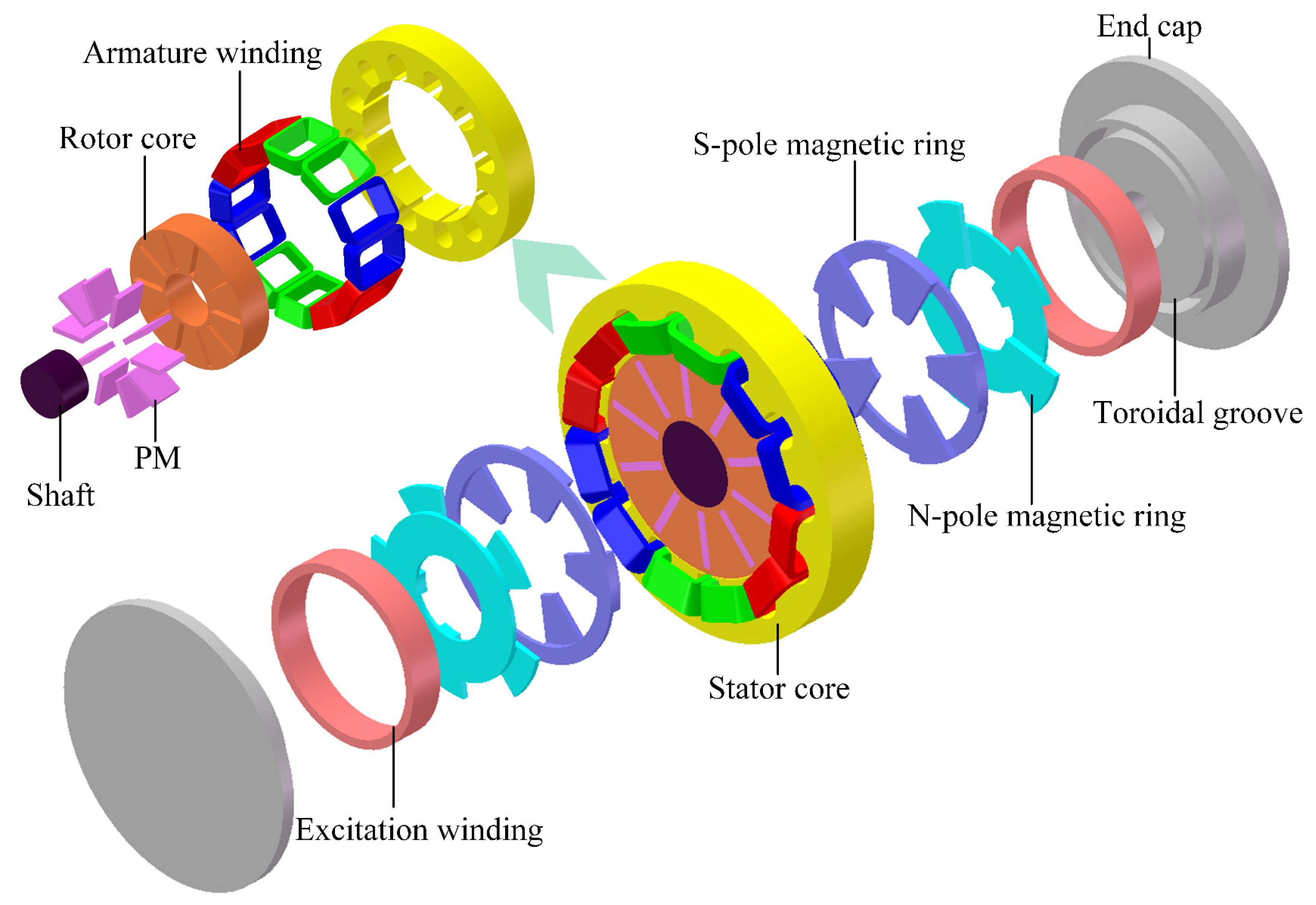
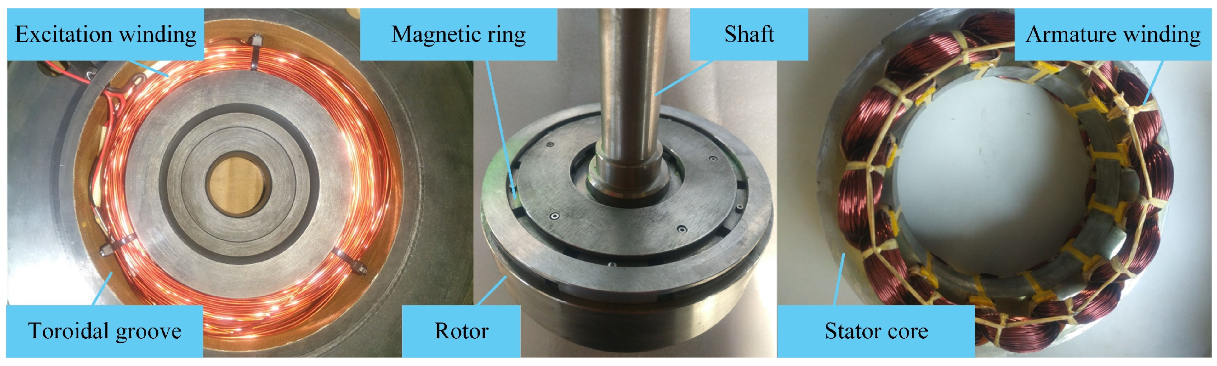
2.1. Structure of ARFHEM

The structure of the ARFHEM is shown in Figure 1. The magnetic flux is composed of a radial PM part and an axial excitation part. The structure of the radial PM is similar to the traditional PMSM structure, which consists of a stator core, a centralized armature winding and a rotor containing PMs. The structure of the axial excitation part is composed of two sets of end caps with toroidal grooves, N-pole and S-pole magnetic ring and exciting winding. The exciting winding is implanted in the toroidal groove of the end cap. In order to make the exciting flux smoothly enter the radial part, the rotor adopts the spoke structure, and each N-pole and S-pole magnetic ring has five-claw pole structures and is fixed in the N-pole and S-pole region at the end of the rotor. Because the axial permeability structure rotates synchronously with the rotor, a brushless excitation structure is formed.

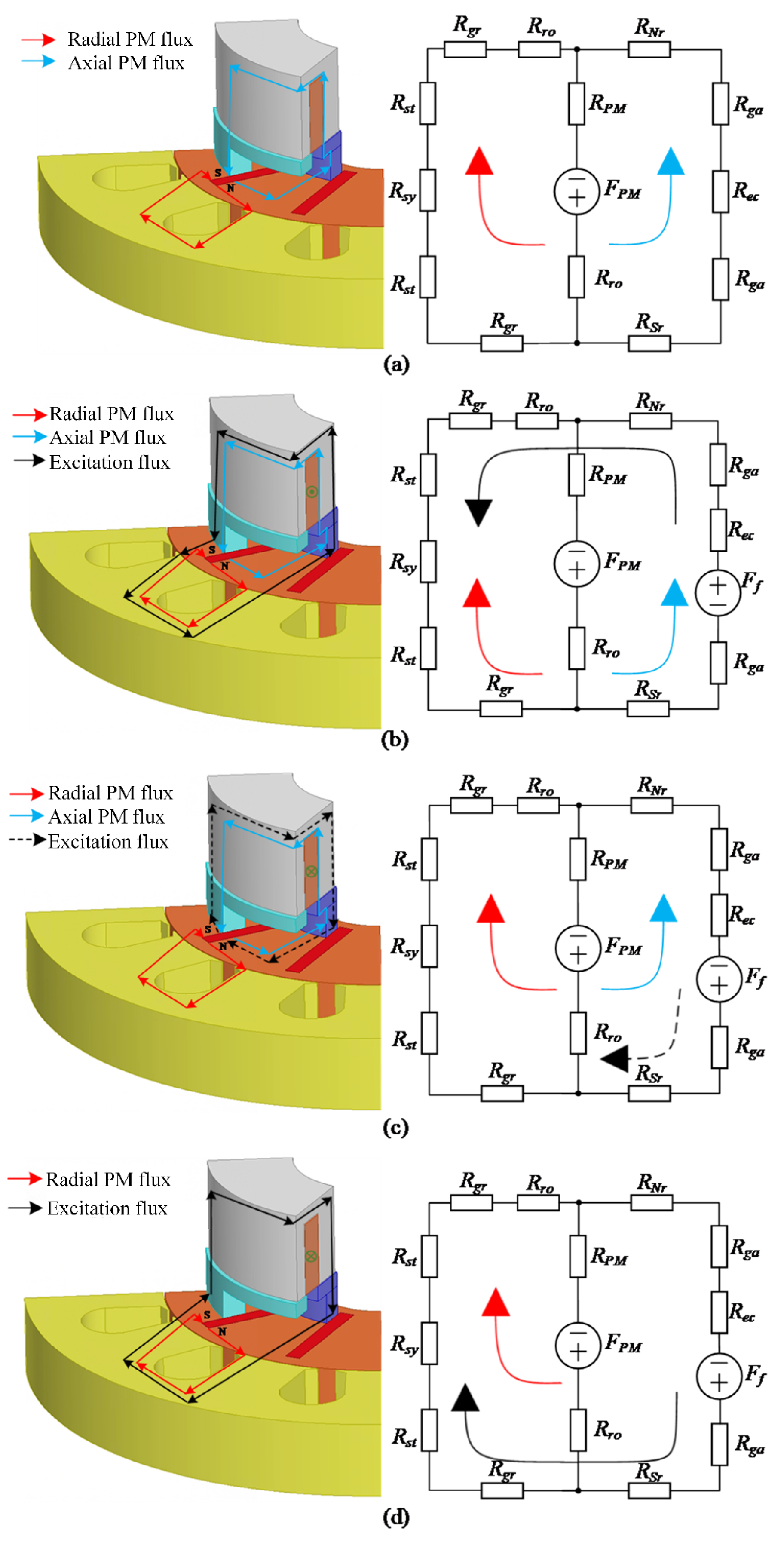
2.2. Operating Principle

The magnetic flux path and equivalent magnetic circuit of ARFHEM are expressed in Figure 2. According to the working condition of the excitation current, ARFHEM is divided into three working states: (1) only PM working state; (2) negative excitation working state; (3) positive excitation working state. To explain the working principle of ARFHEM more clearly, one end of the axial excitation device is ignored.
The axial permeability structure makes the PM provide magnetic flux in both radial and axial directions. In Figure 2a, when the excitation winding does not work, the radial part of ARFHEM is similar to that of PMSM, and the axial PM flux path is as follows: N-pole of PM → rotor core → S-pole magnetic ring → end cap → N pole magnetic ring → S-pole of PM. Then, the radial PM flux can be expressed as
ψ p r = N c × F PM F PM × R PM + R r o R PM + R o + R r 2 × R a   R r 2 + R a   R a
When negative current passes through the excitation winding, the direction of excitation flux is the same as axial PM, but opposite to radial PM, as shown in Figure 2b. At this time, ARFHEM is in the flux weakening state, and the weakening magnetic linkage Δ ψ f w can be expressed as
Δ ψ f w = N c × 2 F f R r + R a
When positive excitation current passes through the excitation winding, the direction of the excitation flux is the same as the radial PM, and ARFHEM is in the flux enhancing state, but it is opposite to the direction of the axial PM flux, which is exhibited in Figure 2c. If the excitation current is small, part of the axial PM flux is forced to flow into the radial flux path, thus increasing the main air-gap flux. In this case, the enhanced flux chain Δ ψ f e 1 can be expressed as
Δ ψ f e 1 = N c × 2 F f R r + R a
As the excitation current increases, the excitation flux will flow directly into the radial flux path through the N-pole and S-pole magnetic ring, thus further increasing the main air-gap flux, as demonstrated in Figure 2d. At this time, the enhanced flux linkage Δ ψ f e 2 can be expressed as
Δ ψ f e 2 = N c × F PM R a + R PM + R r o + 2 F f R r + R a
where R r = 2 R g r + 2 R s t + R s y + R r o , R a = R S r + R N r + R e c + 2 R g a , R PM is the reluctance of PM. R r o is the reluctance of the rotor core. R s t and R s y are, respectively, the reluctances of stator teeth and yoke. R g r and R g a are the reluctances of axial and radial air gaps. R N r , R S r and R e c are the resistances of the N-pole magnetic ring, the S-pole magnetic ring and the end cap. F PM and F f are the magnetomotive forces of PM and excitation current, respectively. N c is the number of turns of armature winding.

3. Analysis of LDR Selection

3.1. Analysis of Constraints of Bypass Effect

The rotor magnetic circuit of ARFHEM is complex, and the magnetic flux bypass path comprises the end cap, N-pole and S-pole magnetic ring. In the bypass, the magnetomotive force of excitation current is used to regulate the bypass flux, as shown in Figure 3, so the air-gap flux can be effectively regulated.
Assuming the air-gap magnetic density is B δ , the magnetic density of the axial magnetic rotor is B a x i a l , the number of pole-pairs is P, and the rotor core length is l F e , then the air-gap magnetic flux Φ r a d i a l on the surface of the rotor in the radial magnetic path is
Φ r a d i a l = π D r o l F e B δ
and the air-gap flux through the axial section of the rotor in the axial magnetic circuit is
Φ a x i a l = π ( D r o 2 D r i 2 ) 4 P ( D r o D r i 2 H 1 ) W p m B a x i a l
Combining (5) and (6), the multiple k Φ of air-gap magnetic flux regulation can be obtained as follows:
k Φ = Φ a x i a l Φ r a d i a l = π ( D r o 2 D r i 2 ) 4 P ( D r o D r i 2 H 1 ) W p m B a x i a l π D r o l F e B δ
Ignoring the inner diameter D r i of the rotor and the distance H 1 between the magnetic steel and the inner and outer diameter of the rotor, considering the influence of the number of pole-pairs of the motor and the thickness of the magnetic steel, then
k Φ = 1 4 ( 1 1 π D r o 2 P W p m 1 ) D r o l F e B a x i a l B δ
Due to the fact that B a x i a l is limited by the rotor saturation characteristics, it cannot be too large (such as No. 10 steel, which is about 2 T). And the air-gap magnetic density has a reasonable value range (about 1 T) when the motor is designed, so the change range is not large. The larger the axial magnetic flux, the better the bypass effect, the wider the magnetic field regulation range, and the larger the multiple of air-gap magnetic flux regulation. As can be seen from (8), the relationship can be expressed as follows:
D r o l F e Φ a x i a l Φ r a d i a l k Φ P Φ a x i a l Φ r a d i a l k Φ
The LDR studied in this paper refers to the ratio of the axial length of the core to the inner diameter of the stator, which is defined as
k λ = l F e D sin
Based on the above analysis, the change of electric LDR and the number of pole-pairs will affect Φ a x i a l Φ r a d i a l , and then affect the multiple of air-gap magnetic flux regulation.

3.2. Analysis of Constraint Conditions in the Selection of LDR

Based on the above calculation method, the magnetic field regulation characteristics of ARFHEMs with different LDRs are studied. The stator inner diameter D sin and core length l F e of the motor are the main structural dimensions, and D sin 2 l F e reflects the volume of the effective part that directly affects the output power. Therefore, when studying the influence of LDR on the electromagnetic characteristics of ARFHEM, D sin 2 l F e remains constant, and the outer diameter D s o u of the stator changes accordingly. Table 1 shows the structural parameters and numerical results of different rotor LDRs.

4. Influence of Different LDRs on Electromagnetic Properties

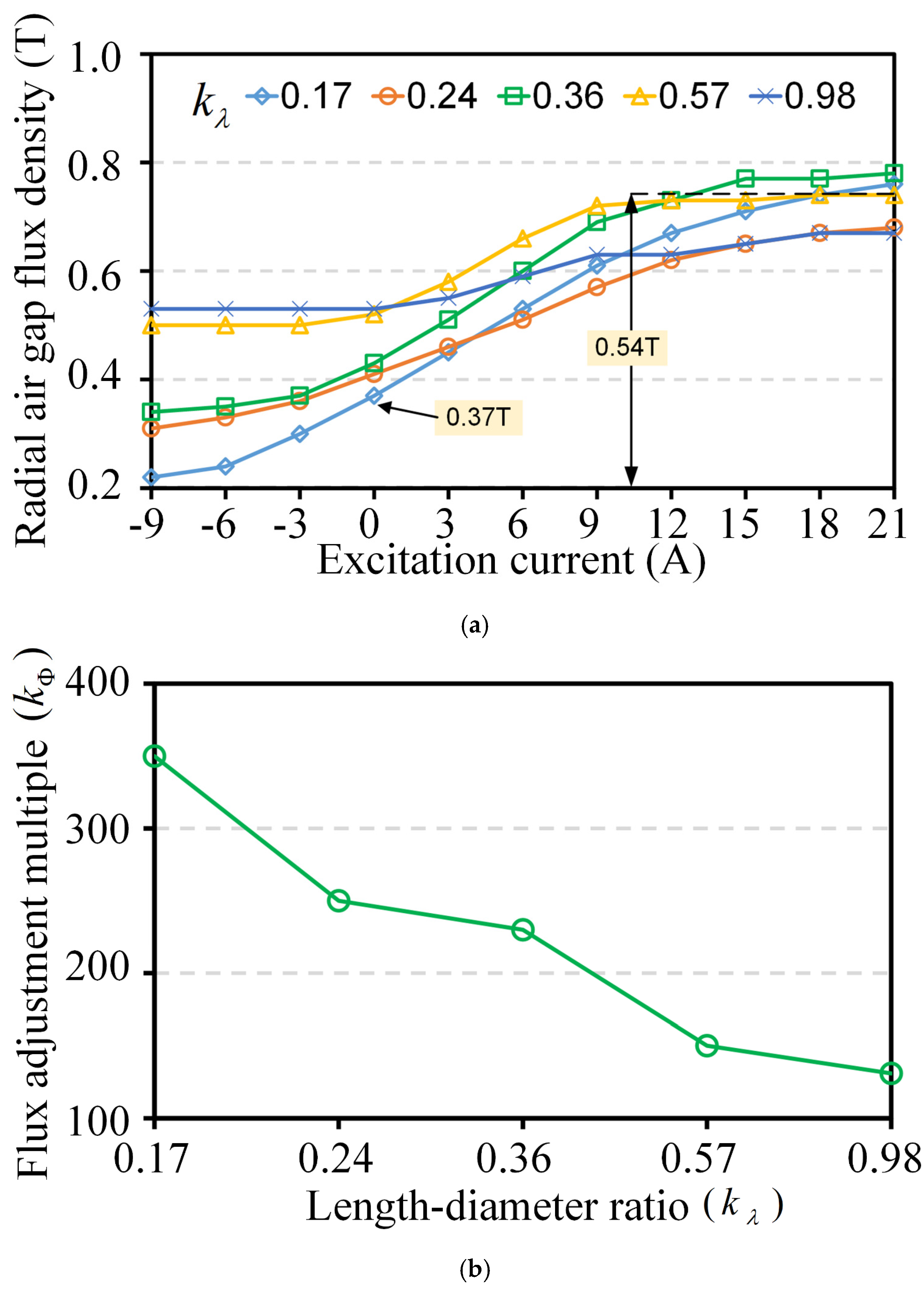
4.1. Influence on the Flux Regulation Properties

The LDR will affect the main air-gap flux of ARFHEM, which is an important index to test the flux regulation. Therefore, to analyze the influence of LDR on the flux regulation performance of ARFHEM, the variation curve of radial magnetic circuit air-gap flux with excitation current of different LDRs is obtained by FEA numerical calculation, as illustrated in Figure 4.
Figure 4a compares the air-gap magnetic flux densities of different LDRs under different excitation currents. It can be seen from the analysis that when the air-gap magnetic flux is only provided with PM (without excitation current), the air-gap magnetic flux density is the highest when the LDR is 0.98, and the air-gap magnetic flux density is the lowest when the LDR is 0.17. When negative excitation current is 9 A, the air-gap flux density of 0.17 is the smallest (0.22 T), and when the positive excitation current is 21 A, the air-gap flux density of 0.36 is the highest (0.78 T). In the range of excitation current variation, the air-gap flux density with the LDR of 0.98 has the smallest variation range, which indicates that the ability of flux regulation characteristics is poor, while the air-gap flux density with the LDR of 0.17 has the best ability of flux regulation with the maximum variation range of 0.54 T, which is 4 times that of the air-gap flux density variation range with the LDR of 0.98. However, in the excitation state of only PM, it is only 0.37 T, because the stator tooth is saturated after the stator inner diameter increases, which causes the main air-gap magnetic flux of the radial magnetic circuit to be weakened.
The multiple of air-gap magnetic flux regulation of different LDRs within the range of excitation current is compared in Figure 4b. The multiple of air-gap magnetic flux regulation of 0.17 is about 350%, while the multiple of air-gap magnetic flux regulation of 0.98 is about 130%. The results show that the multiple of air-gap magnetic flux regulation decreases significantly with the increase in LDR and the air-gap flux regulation characteristics become worse.

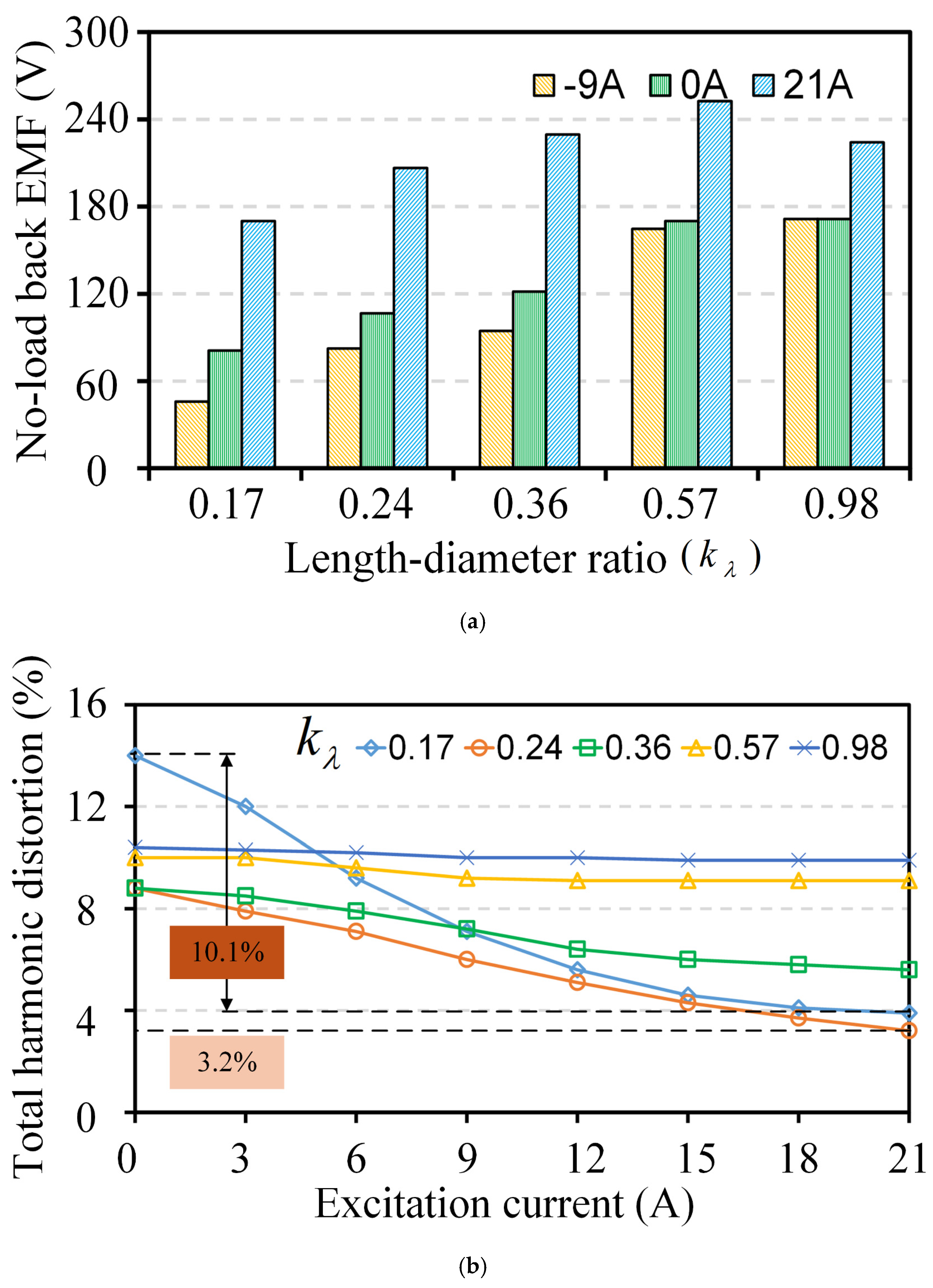
4.2. Influence on No-Load Back EMF and Harmonics

Figure 5a shows the change of the no-load back EMF of the ARFHEM with different excitation currents and LDRs, thus verifying the accuracy of the change in the air-gap flux density. The results show that the no-load back EMF of the motor with the LDR of 0.17 is the lowest under the excitation condition of only PM, which reaches 81 V. The no-load back EMF of the motor with the LDR of 0.98 is similar to ARFHEM with the LDR of 0.57, both of which are 170 V. When the 21 A positive excitation current is applied axially, the back EMF of the motor with the LDR of 0.57 is the largest, which is 252.5 V. Under the three conditions of excitation only by PM, decreasing or increasing magnetic flux, the no-load back EMF of ARFHEM with the LDR of 0.17 is always the smallest, but the back EMF with the excitation current changes, which can reach a maximum of 124 V, and the back EMF of ARFHEM with the LDR of 0.98 can reach a minimum of 53V. The flux regulation ability of ARFHEM with an LDR of 0.17 is 2.35 times that of 0.98.
The total harmonic distortion (THD) of the back EMF of ARFHEM with different LDRs with the excitation current is compared in Figure 5b. The results show that when only PM is used, the THD with the LDR of 0.17 is the highest, at 14%. When the positive excitation current is applied, the THD of the back EMF with the LDRs of 0.17, 0.24 and 0.36 decreases with the increase in the excitation current, mainly because the positive current increases the DC component of the back EMF. When the excitation current is 21 A, the THD with the LDR of 0.24 is the lowest, at 3.2%. There is little change in the THD of the back EMF with the LDRs of 0.57 and 0.98.

4.3. Influence on Output Torque and Loss

The output torque of motors is an important parameter of electromagnetic performance, so it is necessary to study the influence of the LDR on the output torque. In order to study the influence of the LDR on the output torque, the FEA method is used to obtain the variation of the output torque of ARFHEM with different LDRs and the excitation current, as shown in Figure 6.
Figure 6 represents the effect of LDR on output torque. When the excitation current is 0 A, the output torque increases with the increase in the LDR, in which the output torque with the LDR of 0.17 is the lowest, while the output torque with the LDRs of 0.57 and 0.98 is similar, and the maximum output torque appears in the motor with the LDR of 0.98. After the introduction of excitation current, the output torque of the motor increases with the increase in excitation current, and the ability of improving torque output is independent of the LDR, and the increased torque value does not exceed 15 Nm.
ARFHEM is limited by the cooling condition of the rotor, and the heat inside the rotor will greatly increase the temperature of the PM of the motor rotor, which will cause the PM to lose magnetism at high temperature. Therefore, it is necessary to analyze the loss with different LDRs. The FEA calculation method is used to calculate the loss of ARFHEM, and the calculation results are shown in Figure 7. The loss in the motor decreases sharply with the increase in LDR, and then tends towards a gentle reduction state.

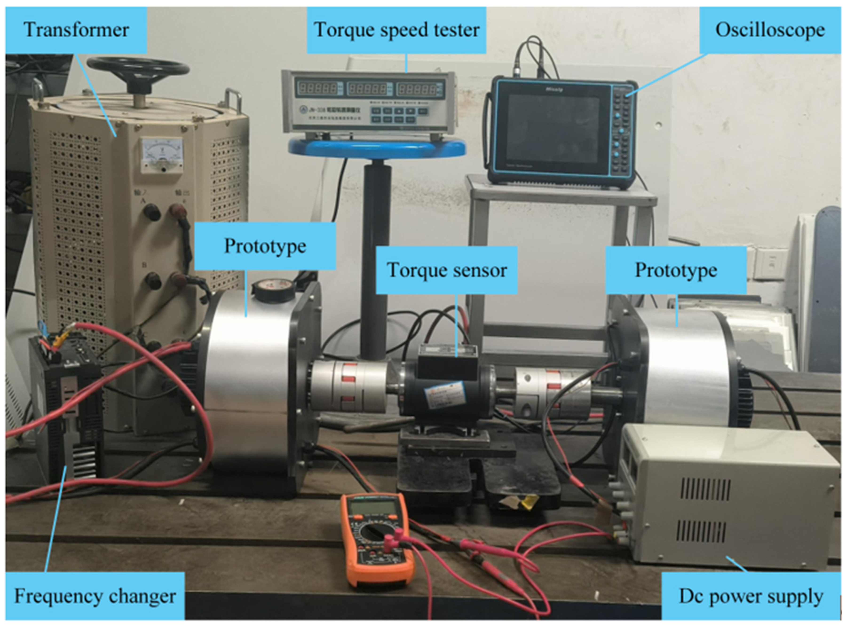
5. Experimental Validation

In order to verify the influence of LDR on electromagnetic properties of ARFHEM studied in this paper, a 12-slot/10-plot ARFHEM prototype with the LDR of 0.24 is manufactured and tested, as shown in Figure 8, whose basic parameters are shown in Table 2. On this basis, the experimental platform is built and shown in Figure 9. In the experiment, two prototypes are used in towing mode. The driving part of the drag motor adopts a DSP module, which is connected with the rotating shaft of the towed motor through a torque sensor to measure the actual torque. The DC power supply is passed into the excitation winding of the towed motor to realize the flux regulation of the magnetic flux.
The verification scheme in this paper is mainly divided into two parts: (1) no-load experiment; (2) flux regulation experiment.

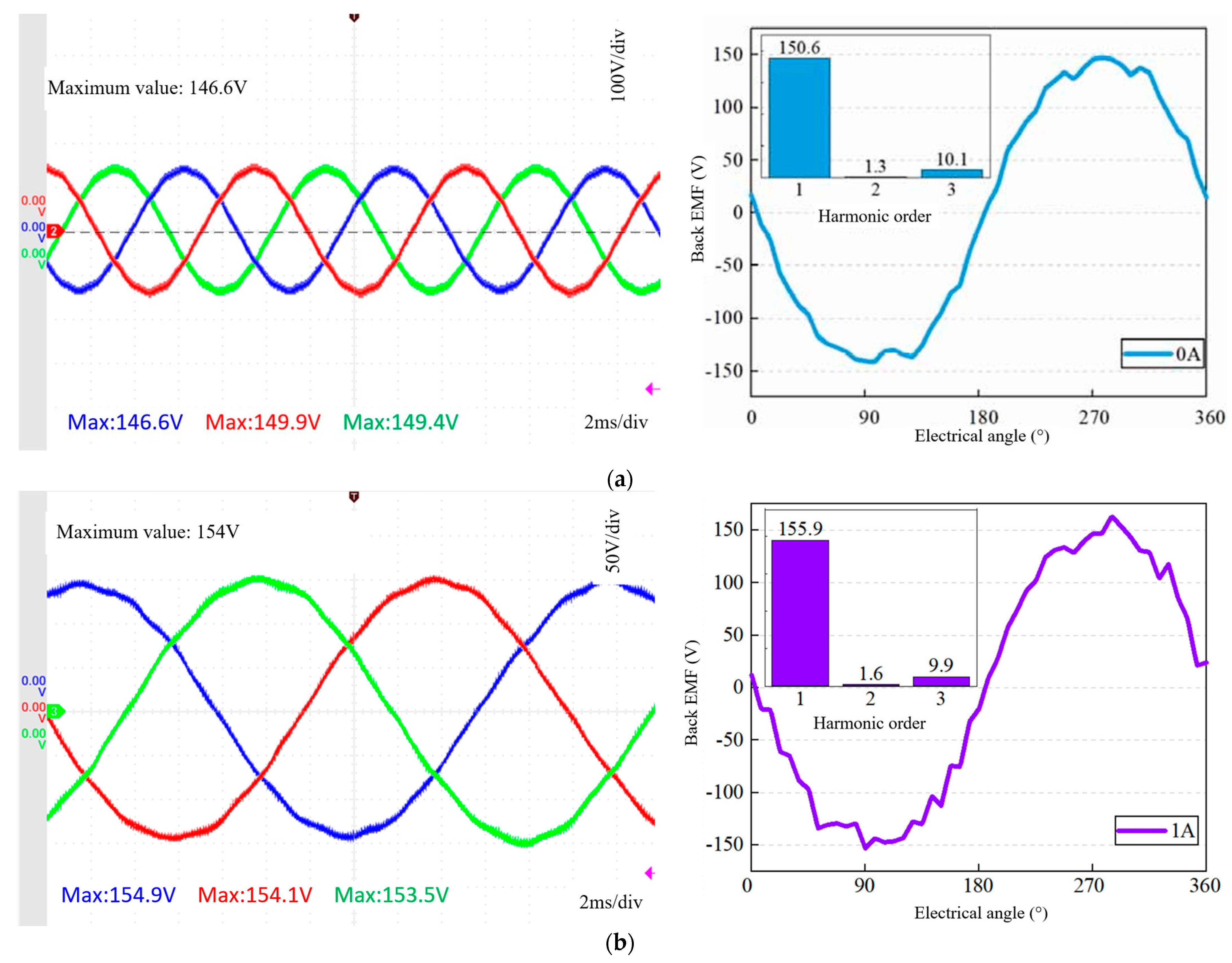
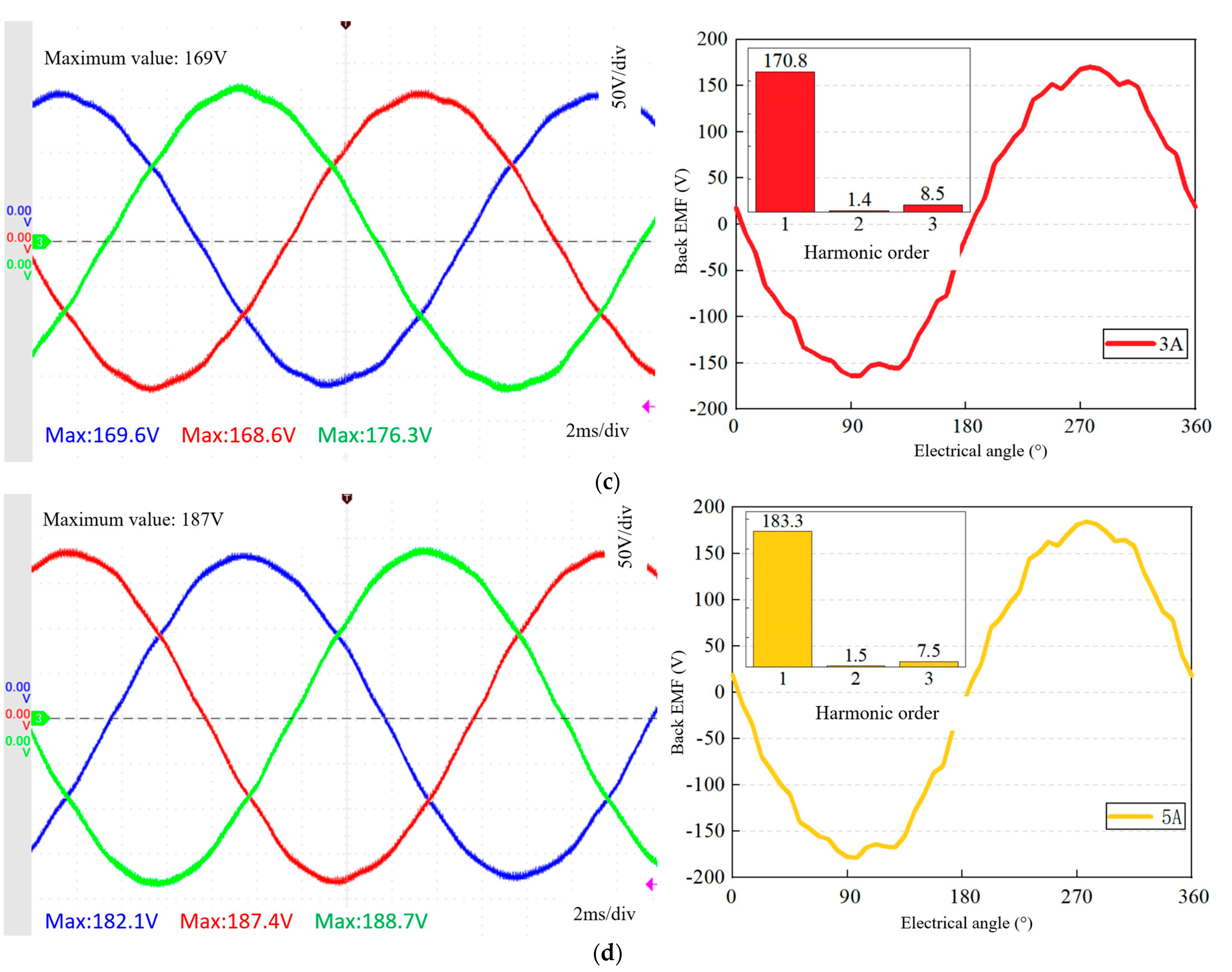
5.1. No-Load Experiment

In order to test the no-load characteristics of ARFHEM, prototype A is used to drag prototype B to test the performance at a rated speed of 250 r/min. The back EMF of the prototype can reflect the change of the air-gap magnetic field, and the test results are shown in Figure 10. In the experimental test, the no-load back EMF presents a sinusoidal distribution with three-phase symmetry, which is basically consistent with the three-dimensional FEA simulation results. The amplitude of the no-load back EMF measured by the experiment of the prototype is 149 V, as illustrated in Figure 10a, and the amplitude of the FEA simulation is 151.3 V, with an error of 1.54%. The experimental data of the back EMF are in good agreement with the simulation data, which verifies the validity of the theory and FEA calculation. The performance is tested at different speeds and the back EMFs are shown in Table 3.

5.2. Flux Regulation Experiment

Under different DC currents of the excitation winding, the three back EMFs of the prototype are tested, respectively, and the flux regulation range can be obtained by analyzing the data, so as to verify the magnetic regulation ability of ARFHEM. Figure 10b–d show the back EMF with different excitation currents. Table 3 shows the comparison between the FEA calculation results and the experiment data.
As can be seen from Table 4, the back EMF of ARHEM increases with the increase in the excitation current. By changing the axial excitation current, the air-gap magnetic field can be flexibly adjusted. The FEA calculation results are consistent with the measured data, which effectively verifies the magnetic flux regulation ability.

6. Conclusions

From the above analysis, LDR is not only important in the design of traditional PMSMs, but also makes it meaningful in the design of ARFHEM, especially when considering the ability of flux regulation and efficiency.
(1)
The air-gap flux regulation ratio with the LDR of 0.17 is about 350%, while the air-gap flux regulation ratio with the LDR of 0.98 is about 130%. The results show that the air-gap flux adjustment ratio decreases significantly with the increase in LDR, and the ability of air gap magnetic field regulation becomes worse.
(2)
The THD of the back EMF decreases with the increase in the excitation current, mainly because the positive current increases the DC component of the back EMF. When the excitation current is 21 A, the THD of the motor with the LDR of 0.24 is the lowest, at 3.2%. The THD of the back EMF of the motor with the LDRs of 0.57 and 0.98 has little change.
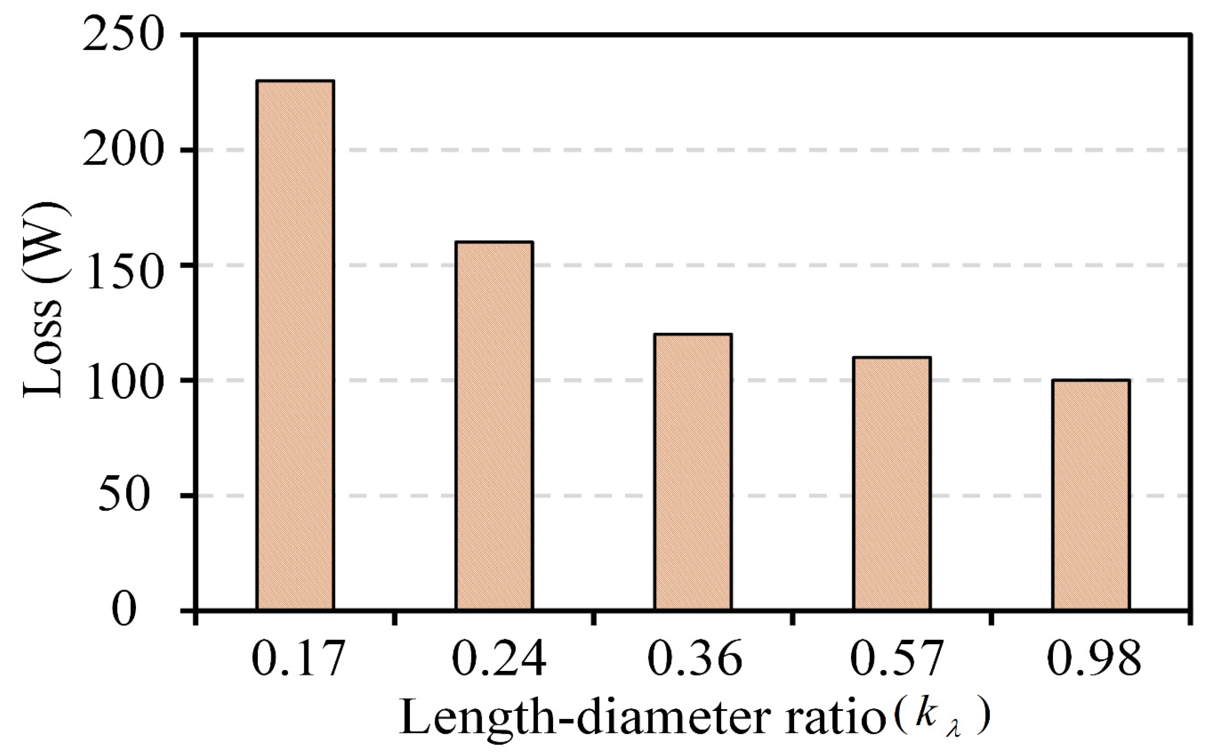
(3)
When the excitation current is 0 A, the output torque of the motor increases with the increase in the LDR. Different from PMSM, after the introduction of excitation current, the output torque of the motor increases with the increase in excitation current, and the ability of improving output torque is independent of the LDR, and the value of improved output torque does not exceed 15 Nm. The loss in the motor decreases sharply with the increase in LDR.

Author Contributions

Conceptualization, Q.W. and W.G.; methodology, Q.W. and H.Q.; software, W.G.; validation, Q.W.; formal analysis, Q.W.; investigation, Q.W. and M.G.; resources, Q.W. and H.Q.; data curation, Q.W. and W.G.; writing—original draft preparation, Q.W.; writing—review and editing, Q.W.; visualization, Q.W.; supervision, Q.W. and J.X. All authors have read and agreed to the published version of the manuscript.

Funding

This research received no external funding.

Data Availability Statement

The original contributions presented in this study are included in the article. Further inquiries can be directed to the corresponding author.

Conflicts of Interest

The authors declare no conflicts of interest.

References

  1. Wang, X.; Wang, Z.; He, M.; Zhou, Q.; Liu, X.; Meng, X. Fault-Tolerant control of dual three-phase PMSM drives with minimized copper loss. IEEE Trans. Power Electron. 2021, 36, 12938–12953. [Google Scholar] [CrossRef]
  2. Chen, Y.; Zang, B.; Wang, H.; Liu, H.; Li, H. Composite PM rotor design and alternating flux density harmonic component analysis of a 200 kW high-speed PMSM used in FESS. IEEE Trans. Ind. Appl. 2023, 59, 1469–1480. [Google Scholar] [CrossRef]
  3. Liu, S.; Song, Z.; Liu, Y.; Chen, Y.; Liu, C. Flux-Weakening controller design of dual three-phase PMSM drive system with copper loss minimization. IEEE Trans. Power Electron. 2023, 38, 2351–2363. [Google Scholar] [CrossRef]
  4. Wu, L.; Lyu, Z. Harmonic injection-based torque ripple reduction of PMSM with improved DC-link voltage utilization. IEEE Trans. Power Electron. 2023, 38, 7976–7981. [Google Scholar] [CrossRef]
  5. Formentini, A.; Trentin, A.; Marchesoni, M.; Zanchetta, P.; Wheeler, P. Speed finite control set model predictive control of a PMSM fed by matrix converter. IEEE Trans. Ind. Electron. 2015, 62, 6786–6796. [Google Scholar] [CrossRef]
  6. Zeng, Z.; Zhu, C.; Jin, X.; Shi, W.; Zhao, R. Hybrid space vector modulation strategy for torque ripple minimization in three-phase four-switch inverter-fed PMSM drives. IEEE Trans. Ind. Electron. 2017, 64, 2122–2134. [Google Scholar] [CrossRef]
  7. Zhang, L.; Fan, Y.; Li, C.; Liu, C. Design and analysis of a new six-phase fault-tolerant hybrid-excitation motor for electric vehicles. IEEE Trans. Magn. 2015, 51, 8700504. [Google Scholar] [CrossRef]
  8. Sulaiman, E.; Kosaka, T.; Matsui, N. High power density design of 6-slot–8-pole hybrid excitation flux switching machine for hybrid electric vehicles. IEEE Trans. Magn. 2011, 47, 4453–4456. [Google Scholar] [CrossRef]
  9. Michieletto, D.; Cinti, L.; Bianchi, N. Hybrid excitation PM synchronous motors: Part II—Finite element analysis. IEEE Trans. Energy Convers. 2022, 37, 495–504. [Google Scholar] [CrossRef]
  10. Zhang, Z.; Liu, Y.; Li, J. A HESM-based variable frequency AC starter-generator system for aircraft applications. IEEE Trans. Energy Convers. 2018, 33, 1998–2006. [Google Scholar] [CrossRef]
  11. Zhang, Z.; Ma, S.; Dai, J.; Yan, Y. Investigation of hybrid excitation synchronous machines with axial auxiliary air-gaps and non-uniform air-gaps. IEEE Trans. Ind. Appl. 2014, 50, 1729–1737. [Google Scholar] [CrossRef]
  12. Liu, Y.; Zhang, Z.; Wang, C.; Geng, W.; Wang, H. Electromagnetic performance analysis of a new hybrid excitation synchronous machine for electric vehicle applications. IEEE Trans. Magn. 2018, 54, 8204804. [Google Scholar] [CrossRef]
  13. Liu, Y.; Zhang, Z.; Geng, W.; Li, J. A simplified finite-element model of hybrid excitation synchronous machines with radial/axial flux paths via magnetic equivalent circuit. IEEE Trans. Magn. 2017, 53, 7403004. [Google Scholar] [CrossRef]
  14. Yang, Q.; Zhao, C.; Zhang, W. Theoretical and experimental analysis of electromagnetic force waves for rotor magnetic shunt hybrid excitation synchronous motor. IEEE Sens. J. 2024, 24, 22511–22522. [Google Scholar] [CrossRef]
  15. Huang, M.; Lin, H.; Yunkai, H.; Jin, P.; Guo, Y. Fuzzy control for flux weakening of hybrid exciting synchronous motor based on particle swarm optimization algorithm. IEEE Trans. Magn. 2012, 48, 2989–2992. [Google Scholar] [CrossRef]
  16. Geng, W.; Zhang, Z.; Jiang, K.; Yan, Y. A new parallel hybrid excitation machine: Permanent-magnet/variable-reluctance machine with bidirectional field-regulating capability. IEEE Trans. Ind. Electron. 2015, 62, 1372–1381. [Google Scholar] [CrossRef]
  17. Chen, Z.; Wang, B.; Chen, Z.; Yan, Y. Comparison of flux regulation ability of the hybrid excitation doubly salient machines. IEEE Trans. Ind. Electron. 2014, 61, 3155–3166. [Google Scholar] [CrossRef]
  18. Tao, M.; Xiaoguang, L.; Wei, X. Optimization Design of Excitation Source Parameters and Magnetic Field Regulation Characteristics Analysis for Parallel Dual-Rotor Hybrid Self-Excited Motor. Electr. Mach. Control. Appl. 2024, 51, 67–75. [Google Scholar]
  19. Xu, L.; Wang, S.; Wang, J.; Li, S. Influence investigation of rotor pole numbers on flux adjustment capability in hybrid excited switched flux permanent magnet machines. Electr. Mach. Control. 2020, 24, 19–26. [Google Scholar]
  20. Wu, S.; Wang, Y.; Tong, W. Design and analysis of new modular stator hybrid excitation synchronous motor. CES Trans. Electr. Mach. Syst. 2022, 6, 188–194. [Google Scholar] [CrossRef]
  21. Jiang, T.; Xu, L.; Ji, J.; Zhu, X. A new partitioned stator hybrid excitation machine with internal magnetic ring. IEEE Trans. Magn. 2022, 58, 8105706. [Google Scholar] [CrossRef]
  22. Wang, X.; Fan, Y.; Chen, Q.; Wu, Z. Magnetic circuit feature investigation of a radial-axial brushless hybrid excitation machine for electric vehicles. IEEE Trans. Transp. Electrif. 2023, 9, 382–393. [Google Scholar] [CrossRef]
  23. Yildiriz, E.; Gulec, M.; Aydin, M. An innovative dual-rotor axial-gap f lux-switching permanent-magnet machine topology with hybrid excita tion. IEEE Trans. Magn. 2018, 54, 8107705. [Google Scholar] [CrossRef]
Figure 1. Structure of ARFHEM.
Processes 12 02942 g001
Figure 2. The flux path and equivalent magnetic circuit of ARFHEM in different excitation current working conditions. (a) Only PM working state. (b) Negative excitation current working state. (c,d) Positive current excitation working state.
Processes 12 02942 g002
Figure 3. Schematic diagram of bypass structure.
Processes 12 02942 g003
Figure 4. Air-gap flux regulation characteristic curve with LDRs. (a) The radial air-gap flux density varies with the excitation current. (b) Variation of the multiple of air-gap magnetic flux regulation with LDRs.
Processes 12 02942 g004
Figure 5. Relation between no-load back EMF and LDR. (a) No-load back EMF. (b) Total harmonic distortion.
Processes 12 02942 g005
Figure 6. The output torque of a motor with different LDRs varies with the excitation current.
Processes 12 02942 g006
Figure 7. Influence of different LDRs on motor loss.
Processes 12 02942 g007
Figure 8. The ARFHEM prototypes.
Processes 12 02942 g008
Figure 9. The test platform of prototypes.
Processes 12 02942 g009
Figure 10. The back EMF varies with the excitation currents. (a) 0A. (b) 1A. (c) 3A. (d) 5A.
Processes 12 02942 g010aProcesses 12 02942 g010b
Table 1. Structural parameters and numerical results of different rotor LDRs.
LDR0.980.570.360.240.17
D s o u (mm)190210230250270
D sin (mm)100120140160180
l F e (mm)10068.45038.2830.25
Table 2. Basic parameters of prototype.
ParametersValueParameters (mm)Value
Rated voltage (V)150Axial air-gap length0.5
Rated frequency (Hz)41.66Stator outside diameter230
Number of poles10Rotor outside diameter139.3
Number of slots12Stator core length50
Armature winding turns150Main air-gap length0.35
Excitation winding turn300PM length40
Number of parallel branches
Material of PM
1
N35
PM breadth
LDR
5
0.24
Table 3. Back EMF at different speeds.
Speed (r/min)Experiment (V)Simulation (V)
25076.5677.62
500149.9151.3
750216.5217.7
1000283.2284.5
Table 4. Back EMF at different excitation currents.
Excitation Current (A)Experiment (V)Simulation (V)
0149.4151.3
1154.1155.5
3169.6171.5
5187.4188.6
Disclaimer/Publisher’s Note: The statements, opinions and data contained in all publications are solely those of the individual author(s) and contributor(s) and not of MDPI and/or the editor(s). MDPI and/or the editor(s) disclaim responsibility for any injury to people or property resulting from any ideas, methods, instructions or products referred to in the content.

