1. Introduction
Carbon fiber reinforced polymer (CFRP) composite materials are made from carbon fibers embedded in a polymer matrix. These materials are renowned for their high strength-to-weight ratio, which makes them suitable for a wide range of applications, such as the construction of aircraft and other transportation vehicles, sporting goods, wind turbine blades, and other applications that require advanced composite materials [
1,
2,
3]. CFRPs have high tensile strength and excellent fatigue resistance, allowing them to withstand high levels of stress and repeated stress without breaking. In recent years, there has been increasing interest in using CFRPs in the construction of buildings and other structures [
4,
5,
6], as well as in medical devices and energy storage technologies, due to their potential for weight savings and improved performance compared to traditional materials. These materials are also utilized in the aerospace, automotive, and sporting goods industries due to their lightweight properties.
The limited service life of these CFRPs is one of today’s environmental issues. The service life of CFRPs is about 50 years, which is the key reason for the recycling concept [
7,
8,
9]. When the CFRPs reach the end of their service life, the carbon fibers are still able to retain their properties. Nevertheless, extensive use of CFRP leads to crucial waste disposal problems. The disposal of CFRPs has become a growing concern due to the increasing volume of material produced each year. The average cost per kilogram of CFRP produced using virgin carbon fibers is approximately between USD 30 and USD 60, with the majority of material being used in the aerospace and automotive sectors [
10]. In these applications, turning CFRP waste into reusable materials and closing the loop in the CFRP life-cycle is the key challenge to increasing resource efficiency and continuing the use of materials [
11].
There are three main routes for recycling CFRPs: mechanical, thermal, and chemical [
12]. Mechanical recycling consists of shredding and grinding of CFRP components into smaller pieces, which can then be used as feedstock for the production of new composite materials [
13,
14]. Thermal recycling usually involves the use of pyrolysis, a process that breaks down the polymer matrix of CFRPs into smaller molecules through the application of heat [
15,
16,
17,
18]. Chemical recycling is related to the use of solvents to dissolve the polymer matrix, allowing for the separation and purification of the carbon fibers [
19,
20]. Despite the potential for recycling CFRPs, the current rate of recycling is relatively low, with only around 5% of CFRP material being recycled each year. The average cost per kilogram of recycled CFRP is much lower than that of virgin carbon fiber reinforced polymer, making it a cost-effective alternative to the production of new material [
10]. However, the lack of infrastructure and specialized equipment for recycling CFRPs remains a significant barrier to increasing the rate of recycling. Furthermore, the development of new manufacturing techniques and the increasing demand for one-dimensional CFRPs are likely to drive down production costs in the future [
21,
22].
A significant concern associated with the recycling of carbon fibers and carbon fiber reinforced polymers (CFRPs) is the potential loss of added value resulting from the recycling process. The mechanical properties and performance of the final recycled material can be influenced by the length of the fibers present, with short fibers, typically less than 1 mm in length, and long fibers, typically longer than 1 mm in length, exhibiting different characteristics [
23]. Short fibers are more compatible with traditional polymer matrix composite manufacturing techniques, but possess relatively low mechanical performance in comparison to long fibers [
24,
25]. Conversely, long fibers exhibit higher strength and stiffness, and are less prone to pullout or debonding from the matrix [
26]. Longer fiber lengths allow for a near one-dimensional orientation, which improves the mechanical behavior of the composites. This implies that long fibers tend to preserve more added value and require less energy for mechanical reduction.
Fiber-matrix adhesion in CFRPs is another critical factor that directly affects the mechanical behavior of these materials. Plasma treatments are a commonly used method for surface modification of carbon fibers to improve fiber-matrix adhesion [
27,
28,
29]. The use of plasma treatments represents a quick, environmentally friendly, and non-toxic dry process that modifies surfaces without altering bulk properties [
30]. Particularly, low-pressure plasma (LPP) treatment is a cost-effective method for modifying material surfaces at the microscopic level without the need for labor-intensive processes or chemicals [
31]. This technique allows for the controlled and reproducible modification of the surface of various materials to improve their bonding capabilities or to impart new surface properties. Additionally, LPP can be applied over a wider area to completely cover surfaces. As such, LPP offers a fast, clean, green, and efficient treatment option for carbon fibers in the production of CFRPs [
32].
Many research studies are unable to attain definitive results due to a deficiency in design. This can be avoided through a properly implemented experiment, as it is a design error rather than a systematic issue [
33]. An analysis of influence may be utilized to identify implicit problems in order to ascertain the suitability of a decision and to gain a comprehensive understanding of the obtained conclusions [
34]. When planning the testing of discontinuous fiber composites, it is essential to determine whether to follow a standard or to consider alternative approaches.
Factorial experimental design, in general, involves the analysis of various factors that can influence an experiment. Factorial design is a powerful tool for understanding the complex interactions between processing or manufacturing parameters [
35]. Therefore, factorial design allows for the identification of the optimal combination of levels given to the factors through the testing of relevant hypotheses related to the various factors and the estimation of their effect on the test results. It utilizes a linear statistical model for predicting responses for each factor through the addition of a common parameter for all combinations of factor levels. However, factorial design is also subject to several limitations. These include the limited number of factors that can be studied simultaneously, the potential for interactions between factors to impact the response, and the number of levels that can be used for each factor. Additionally, factorial design relies on the assumption of normality in the response, which may not always be valid [
36]. Moreover, factorial design can become complex when dealing with large amounts of data and multiple factors and levels, requiring specialized software or statistical techniques for analysis.
The DOE (Design Of Experiments) method is a fractional factorial experiment in which only a carefully chosen subset of the treatment combinations necessary for a full factorial experiment to be conducted is chosen [
37]. This method is more effective than other design of experiment methods, such as Taguchi, which is less time-consuming but ignores interactions between factors [
38].
In the present research, a comprehensive characterization of the epoxy resin has been carried out through the thermal and chemical study of its curing. After manufacturing the composites, the DOE method has been applied to study the effect of various processing parameters, such as reinforcement length (L), post-curing (C), and plasma treatment (P), on the properties of the resulting composite materials. By comparing the results at two levels of each factor (high and low), the optimal processing conditions for the production of CFRPs have been identified.
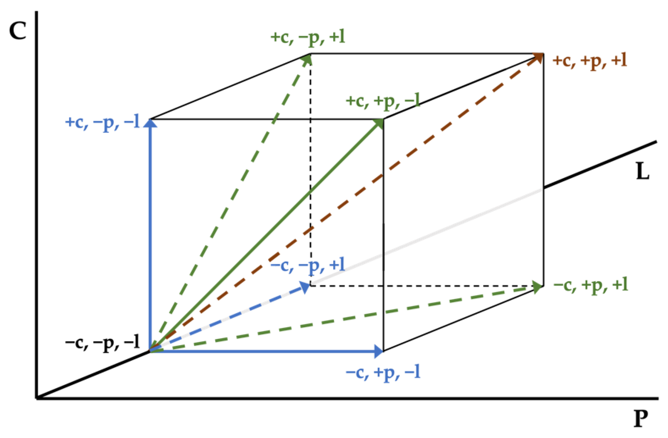
Figure 1 depicts factors in a three-dimensional space, with each factor being represented on a different axis. The results are enhanced with SEM micrographs showing the reinforcement-matrix interface in the case of carbon fiber and epoxy resin.
Therefore, the objective of this research is to design a process for the incorporation of recycled carbon fibers and composite materials into new composite materials. Mechanical recycling is selected as the recycling method due to its lower energy requirements, reduced generation of waste, and ability to maintain the integrity of the fibers in comparison to thermal and chemical recycling methods. A factorial design is employed to determine the most significant parameters impacting the properties of the manufactured composite material. The results obtained from the factorial design are then applied to a new composite material consisting of epoxy resin reinforced with a commercially available CFRP mechanically recycled in the shape of rods. This mechanical recycling process differs from current methods, which predominantly consist of grinding and are consequently more energy-intensive, by preserving the influence of fiber length to retain added value.
2. Materials and Methods
2.1. Materials
A rigid epoxy system consisting of an epoxy resin (SR 8500, Sicomin Epoxy Systems, Châteauneuf-les-Martigues, France) and a hardener (SD 8601, Sicomin Epoxy Systems, Châteauneuf-les-Martigues, France) was selected as matrix. The resin and hardener are mixed following a 100/35 weight ratio at room temperature conditions (23 °C/50% RH) The epoxy system has a clear liquid aspect and SD 8601 hardener is reported to have an ultra-slow reactivity. The manufacturer recommends performing a post-curing of 8 h at 80 °C after one day to achieve optimal properties.
Table 1 presents a comparison between the epoxy system without post-curing and the epoxy system after undergoing the previously mentioned post-curing process. The last two rows in
Table 1 present the data provided by the manufacturer and the data calculated experimentally, respectively. Hereafter, the experimental data from the last row will be considered for comparison purposes.
Carbon fiber fabric (GG 600 T, MEL Composites, Barcelona, Spain) and pultruded carbon fiber plates (Carbodur S 512, Sika S.A.U. España, Alcobendas-Madrid, Spain) were selected as reinforcement. Carbon fibers were cut in the shape of bundles, manually separating the fibers inside the bundles aiming to keep their one-dimensional nature. Carbon fibers’ length was reduced to the desired values mechanically by means of scissors. In the case of CFRP as reinforcement (see
Table 2), the plates were mechanically cut to obtain 1–1.5 mm width rods, keeping the original thickness of 1.2 mm. Therefore, both reinforcements are examples of mechanically recycled fibers and CFRPs, respectively.
2.2. Manufacturing of Specimens
The specimens were manufactured in silicone molds in all cases, with a constant length/width ratio higher than 10 for all sets. In addition, a carbon fiber content of 13 ± 1% in weight was set. In the case of plasma treatment being required, it was carried out in a vacuum chamber with air atmosphere on the carbon fibers or on the mechanically recycled composite rods before the final composites were manufactured. The composites were demolded at least 7 days after the epoxy components were mixed and the specimens were fabricated. If post-curing was necessary, 24 h after mixing the components, the post-curing was carried out in an oven at 80 °C for 8 h in an air atmosphere. In this case, the demolding of composites was carried out 16 h after removal from the oven, when both the mold and the samples were at room temperature.
2.3. Surface Modification
Before manufacturing the composites and in some of the cases, carbon fibers were treated with LPP in a plasma cleaner chamber (Harrick, Ithaca, NY, USA) in an air atmosphere to produce plasma at a pressure of 300 mtorr. After achieving a stable vacuum in the chamber, carbon fibers were treated for 2 min at a power of 30 W.
To ensure the preservation of the surface modification caused by the LPP treatment, the composites were manufactured immediately following the removal of the carbon fibers from the vacuum chamber.
2.4. Morphology Study
Carbon fibers’ surface, as well as the fracture surface of the composite specimens after tensile testing, were analyzed using a scanning electron microscope (SEM) (Philips XL-33 FEI EUROPE SEM, Eindhoven, The Netherlands) in order to study the effect of the LPP treatment. The specimens were coated with gold in a Polaron high-resolution sputter coater to serve as a conductor for the electrons and provide sufficient contrast in the SEM micrographs.
2.5. Mechanical Characterization
To evaluate the mechanical behavior of the epoxy and the composites manufactured, tensile tests were carried out on a universal testing machine (Microtest, Madrid, Spain). A load cell of 20 kN was used for test data acquisition. The test speed used was 1 mm/min since the objective is a quasi-static test. To avoid slippage during testing, P180 sandpaper was used between the specimens and the grips. At least five specimens were tested per set.
Stress is calculated, according to ISO 527-5, as the ratio between the force and the area of the specimen, the latter being assumed constant during the test. Strain is defined, according to the same standard, as the ratio between the increase in length experienced by the specimen and its initial value, the latter taken as the distance between grips. Finally, the elastic modulus is defined, similarly with respect to the aforementioned standard, as the ratio between the stress and strain increments in the strain range between 0.0005 and 0.0025.
2.6. Thermal and Chemical Characterization
The materials were characterized by differential scanning calorimetry (DSC) and Fourier-transform infrared spectroscopy (FTIR).
A DSC 822 (Mettler Toledo GmbH, Greifensee, Switzerland) was used to determine the curing kinetics of the epoxy. Samples with weights of 8 ± 1 mg were placed in 40 μL aluminum crucibles and under nitrogen atmosphere for testing.
To determine the curing kinetics of the epoxy, scans consisting of non-isothermal heating from −20 to 200 °C at different heating rates of 5, 10, and 20 °C/min were performed. By means of STARe software (Mettler Toledo GmbH, Greifensee, Switzerland), model-free kinetics (MFK) was used to calculate the degree of conversion at different temperatures based on the thermograms obtained at different heating rates. The analysis of these values enables the calculation of the activation energy as a function of the degree of conversion [
41,
42]. A comprehensive understanding of the curing process of the resin is of importance, as optimal curing conditions will yield the most favorable mechanical performance.
Additionally, the glass transition temperature (Tg) was studied by performing cycles at 20 °C/min from −20 to 200 °C. Tg is a second-order transition, without a phase change, but rather a change in the volume of the sample due to the mobility of the chains.
A Bruker Tensor 27 spectrometer (Bruker Optik GmbH, Ettlingen, Germany) was used to obtain the infrared spectra of the samples. The attenuated total reflectance (ATR) technique was used to analyze the chemical modifications produced at about 5–10 μm depth of the sample. A diamond prism was used and the angle of incidence of the infrared radiation was 45°. Forty scans with a resolution of 4 cm−1 were obtained and averaged between 600 and 4000 cm−1.
3. Results and Discussion
3.1. Matrix Characterization: Curing of the Epoxy Resin
Thermal characterization of the epoxy matrix was performed using DSC to study the curing kinetics and determine the glass transition temperature. In addition, a chemical analysis of the matrix was conducted using FTIR-ATR to examine the chemical changes that occurred during the curing process and assess other aspects related to the curing of the matrix [
43].
3.1.1. Differential Scanning Calorimetry (DSC)
The curing process of the epoxy resin is studied using thermograms at different rates. The corresponding Sicomin 8500 data are shown in
Figure 2. The curves shift to different temperatures (T
p) depending on the heating rate (β). The integrals of the curves have similar areas, representing the heat released during the curing process (ΔH).
Figure 2 illustrates the displacement of temperature peaks to higher temperatures as the heating rate increases. In addition,
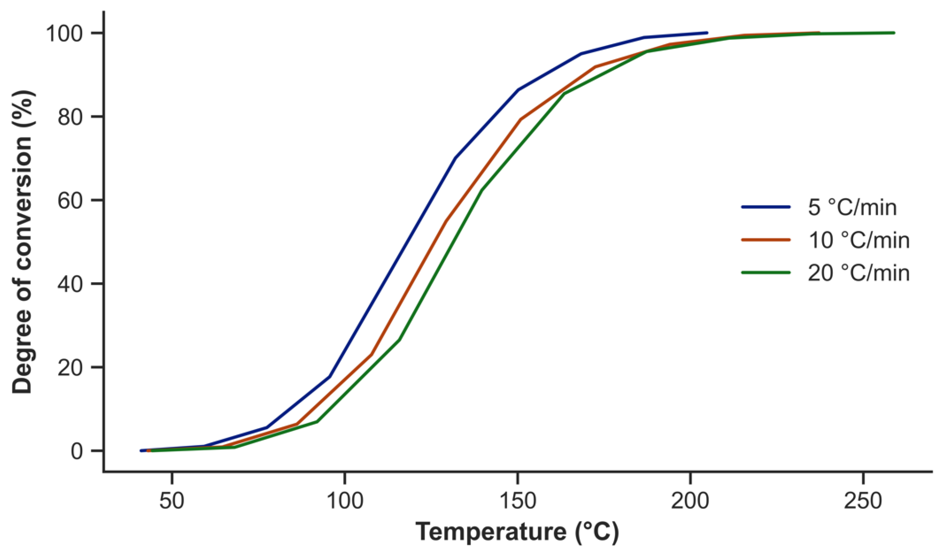
Table 3 presents the heat released by Sicomin 8500 during the curing process. Using the STARe software, the degree of conversion is calculated from the initial thermograms at different rates These curves are shown for Sicomin 8500 in
Figure 3. It is necessary for the application of MFK that the curves do not intersect, and since this requirement is satisfied, the activation energy can be calculated using the STARe software as a function of the degree of conversion based on these curves.
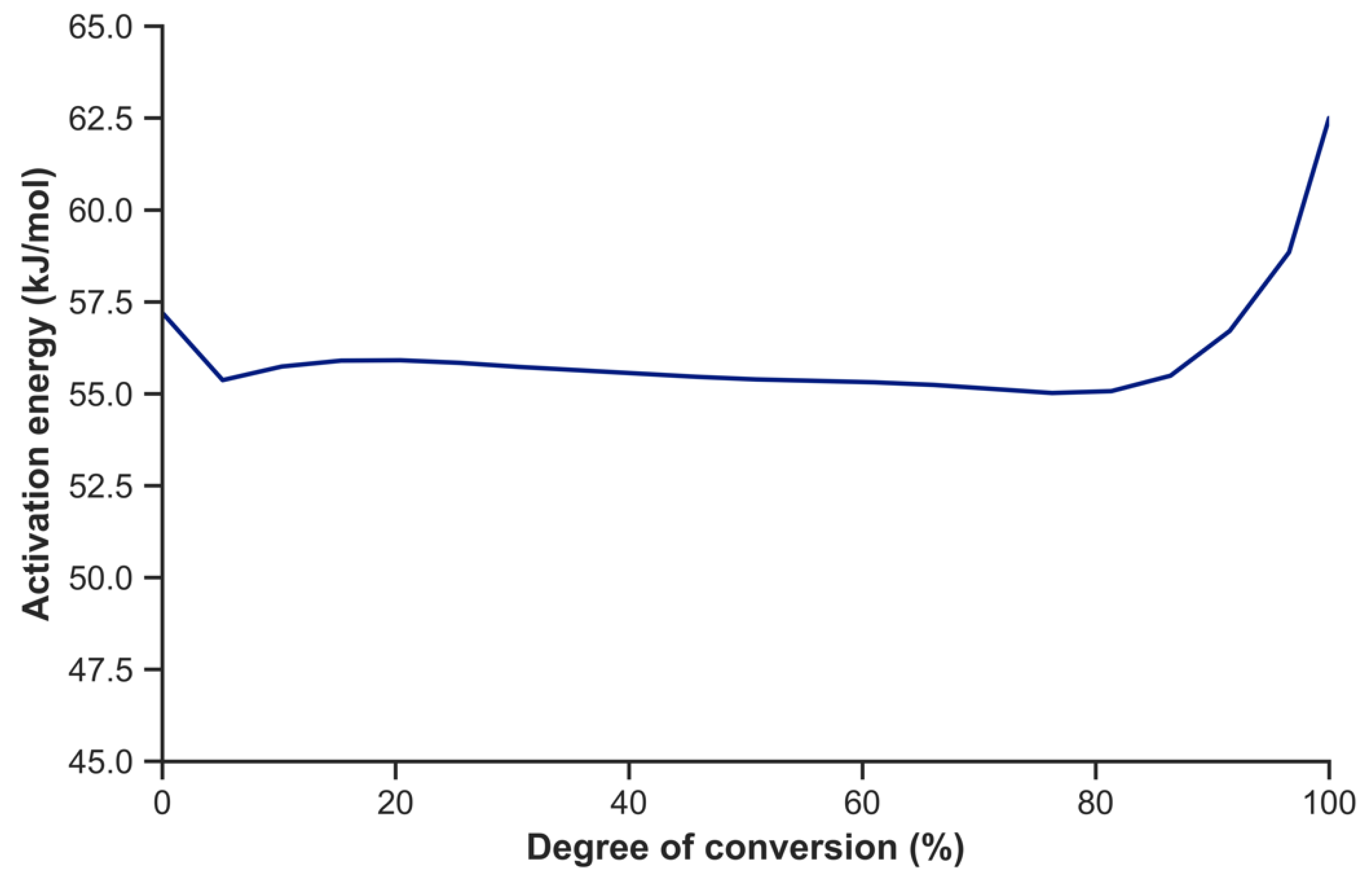
Figure 4 exhibits the activation energy for the epoxy resin as a function of the degree of conversion [
44]. The activation energy of common industrial epoxy is known to be influenced by a range of factors. These include, but are not limited to, the chemical composition of the epoxy, the curing conditions (temperature, time, and humidity), the presence of impurities such as moisture or contaminants, the aging of the epoxy, even when properly stored, and variations in measurement conditions, including temperature and humidity. Three well-defined phases are observed. In the first zone, corresponding to the n-order reaction, a higher level of energy is required to initiate the reaction; in an intermediate zone, during the autocatalytic process, the energy needed to maintain the reaction is practically constant; finally, a greater energy input is required to complete the crosslinking reaction [
41,
45,
46]. The necessity for a significantly higher energy input to complete the curing reaction confirms the necessity for post-curing the resin or, alternatively, a longer curing time at room temperature.
Based on the calculation of the activation energy, the isothermal curing at constant temperature for the epoxy resin can be simulated.
Table 4 shows this simulation for Sicomin 8500. It should be noted that it is not possible to simulate the 100% curing environment as the error incurred would be very high. Similarly, the beginning of the reaction is taken as 0.1–0.2% cured.
Table 4 reports that the curing time at room temperature is 10,140 min (7 days and 1 h), an excessively long time for the curing of an epoxy resin in an industrial process. At the proposed post-curing temperature (80 °C), 99% curing is achieved in 260 min (4 h and 20 min).
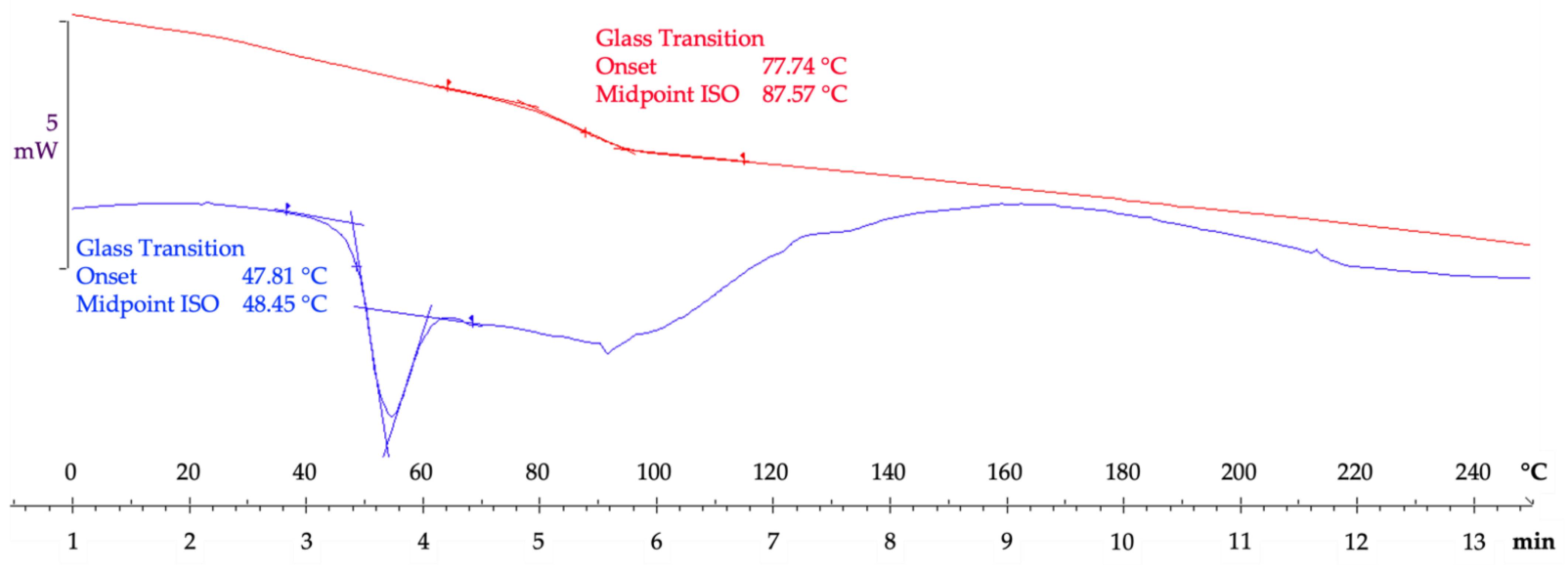
Once the resin has been prepared, the T
g is calculated by DSC. In this case, two scans were made on the same sample to erase the thermal history and determine if the resin has finished curing. Sicomin 8500 presents an overlapped T
g with a relaxation enthalpy, followed by a curing peak in the first scan after curing at room temperature, performed 24 h after mixing the components. The presence of a curing peak indicates the epoxy resin is not fully cured. Once the thermal history has been erased and the adhesive has finished curing with post-curing, in the second scan it has a T
g of 88 ± 1 °C, as shown in
Figure 5. A higher T
g indicates greater crosslinking and, consequently, higher stiffness, confirming what was observed in the mechanical properties in terms of higher stress [
47].
3.1.2. Fourier-Transform Infrared Spectroscopy (FTIR)
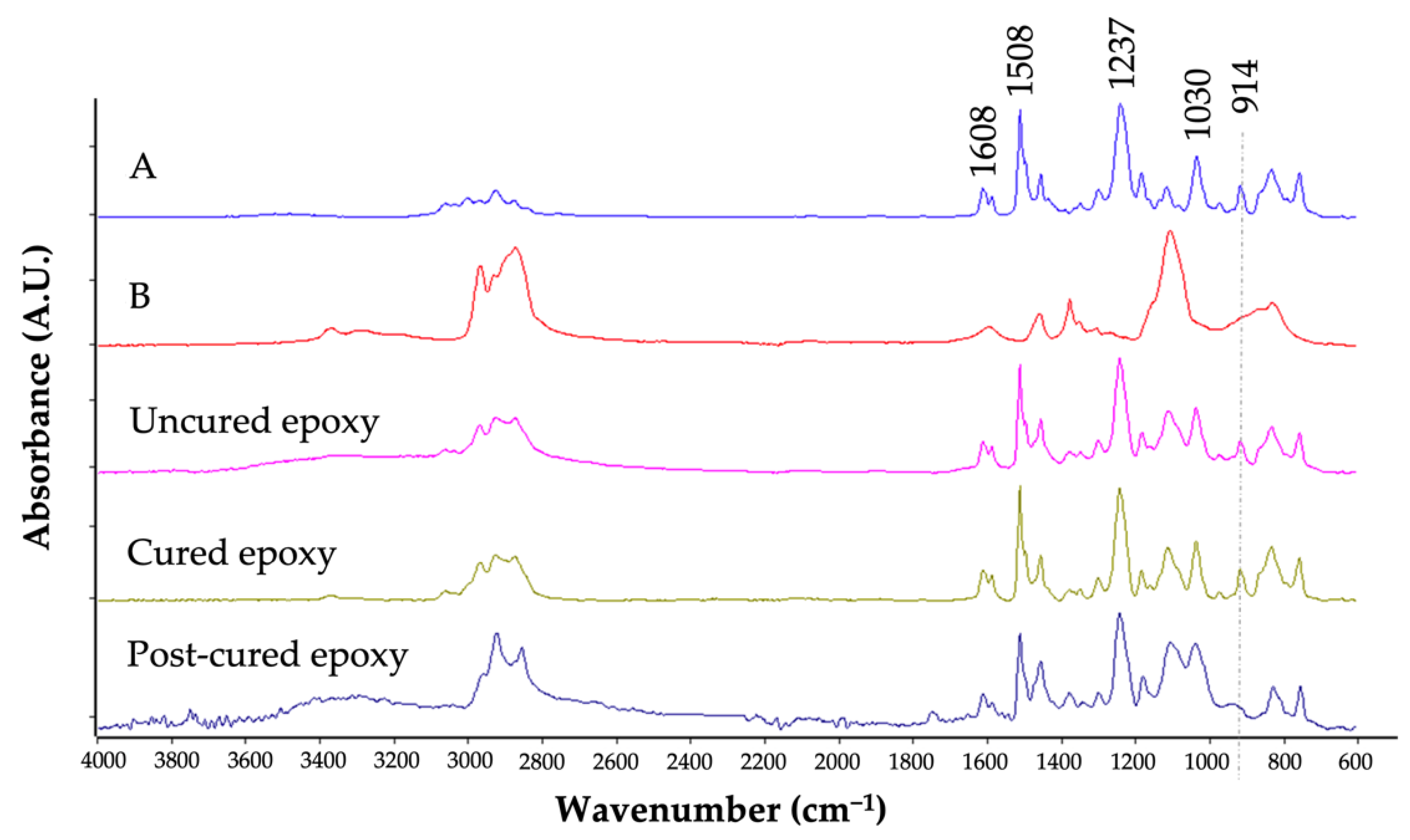
Figure 6 shows the spectra of components A and B of Sicomin 8500 resin before mixing, once mixed (uncured), cured, and after post-curing. It is clearly seen that the peak at 914 cm
−1 disappears after post-curing. However, if post-curing is not carried out, after 24 h of curing at room temperature, the peak continues to appear. This peak corresponds to the oxirane group, which opens up with the reaction with the hardener or component B, giving rise to OH groups that autocatalyze the reaction and produce the crosslinking of the resin. The hardener (component B) is a polymer of lower complexity, where a greater presence of CH
2 and CH
3 aliphatic groups can be observed. The rest of the peaks can be observed in
Table 5 and correspond mainly to C-C or CH bonds, with the presence of aromatic rings being important in this case, which increase the rigidity of the epoxy due to the lack of mobility in double bonds. These observations, along with those obtained by means of DSC, confirm that Sicomin 8500 is an epoxy with a reduced level of filler additives.
3.2. Carbon Fiber as a Reinforcement
Composite material specimens made of carbon fiber have been mechanically tested through tensile tests.
Table 6 collects the design factors and the test plan chosen.
Figure 1 represents the factors in a three-dimensional space, each factor being represented on a different axis. Eight sets of specimens have been designed to cover the cases shown in the table. On the one hand, it is possible to apply a LPP treatment to the carbon fibers before they are impregnated with epoxy (factor P). On the other hand, once the composite has been manufactured, it can be subjected to a post-curing process to achieve faster curing of the resin while improving certain mechanical properties (factor C). Finally, the length of the carbon fiber can be either 18 or 40 mm (factor L). It should be noted that certain factors, such as the porosity in the final composite, the width of the carbon fiber beams used, or the deviation of the fibers from the hypothesis of one-dimensionality (both in the horizontal plane and in the vertical plane), among others, have not been considered.
Table 7 exhibits the mechanical results obtained after tensile tests. The average of five samples is shown along with the standard deviation as a measure of variability. Furthermore, the coefficient of variation (CoV) is represented as the ratio between the standard deviation and the average, expressed in percentage. Due to the inherent inhomogeneity of the specimens, in addition to effects not considered, such as deviation from the hypothesis of one-dimensionality in the horizontal and vertical planes, the CoV shows high values in almost all the tested sets and for all the measured responses.
Table 8 presents a matrix representation of the individual effects of each factor and their interactions. By analyzing this matrix, in conjunction with the experimental data provided in
Table 7, it is possible to extract several key data points: the average response, three main factor effects, three interaction effects between pairs of factors, and one interaction effect involving three factors. Utilizing Yates’ algorithm allows for the calculation of influence values, represented in
Table 8. To determine the Yates order for a fractional factorial design, it is necessary to understand the confounding structure of the design. The experimental data obtained for each combination of parameters are used to calculate the effect of each factor and interaction on the response, which is achieved by adding or subtracting the averages of the responses. Therefore,
Table 8 lists the effects and interactions of the factorial experiment, with the influence factors serving as dimensionless indicators that can be compared based on their relationship to the order of magnitude of the response.
In the sample space, it can be seen how the factor that presents the most positive impact in terms of stress is the application of a post-curing (C), followed by using long fibers (L), and the combination of those two (C × L); meanwhile, a LPP treatment (P) and its combination with any other factor leads to a reduction in this response.
The length of the carbon fiber (L) exhibits the most significant positive change in terms of strain, followed by a combination of LPP, post-curing, and long fibers (P × C × L), and a combination of post-curing and long fibers (C × L). In this case, the combination of LPP and long fiber leads to a decrease in strain at maximum failure.
Finally, the stiffness, represented by the elastic modulus, is favored by the application of post-curing, followed by the incorporation of long fibers (with a positive value close to zero). As in the case of stress, the use of LPP and its combination with the remaining factors leads to a decrease in the elastic modulus. Similarly, the combination of post-curing and long fibers results in a reduction in stiffness.
From the analysis of the influence values shown in
Table 8, the key factors are the application of post-curing to the resin, an increase in fiber length, and a combination of both. Regarding post-curing, it is the factor that most improves tensile strength and provides greater stiffness to the material. This need for post-curing coincides with the information provided by the manufacturer in the technical data sheet referred to in
Table 1. Additionally, this coincides with the results obtained from the chemical and thermal characterization of the epoxy resin, which indicated that post-curing improved the mechanical properties of the resin, increasing its T
g, and demonstrated that post-curing ensured the opening of the oxirane rings that confirm the completion of the epoxy crosslinking process. In terms of fiber length, increasing the length of the carbon fiber beams from 18 to 40 mm has an effect almost as positive as post-curing on tensile strength while having the most positive effect on strain at maximum stress. However, fiber length does not modify significantly (it should be noted that the obtained influence values are relative) the stiffness of the composites, as occurs with the application of post-curing. Finally, the combination of post-curing and fiber length also yields very positive results in terms of stress and strain at maximum stress, although stiffness is compromised. In general, the energy absorption capacity before breaking, known as toughness, of the composites that either cure with post-curing, incorporate long fibers, or combine post-curing and long fibers, is higher than that of the rest of the sets. Additionally, it seems clear that the LPP treatment leads to a general decrease in the mechanical behavior of the composites.
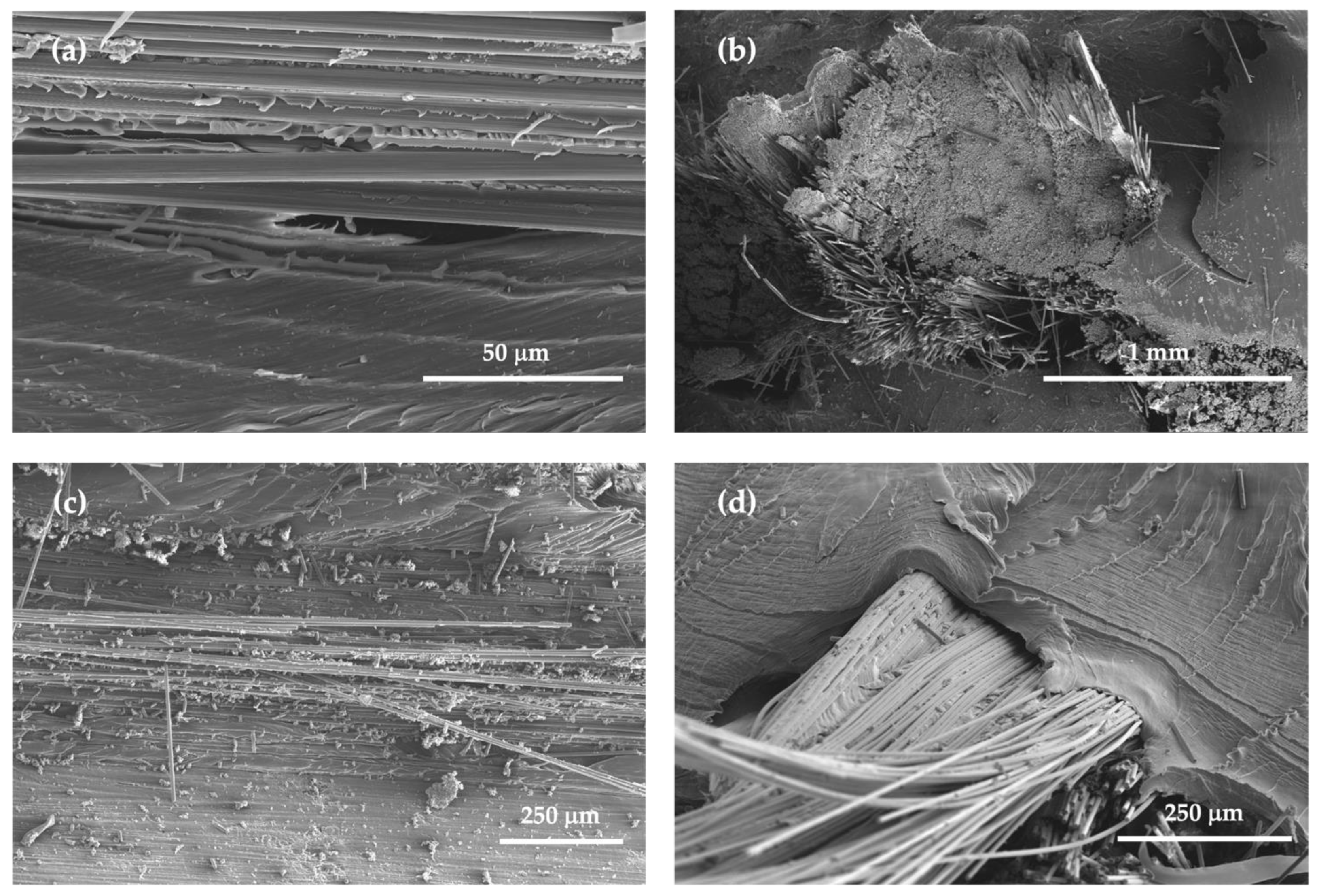
To gain a deeper understanding of the impact of LPP treatment on carbon fibers,
Figure 7 exhibits samples that have been studied using SEM. The examination was focused on the samples that yielded the most promising results, as determined by a factorial design study. These samples included the combination of post-cured and long carbon fibers (C × L), as well as the combination of LPP treatment, post-cured and long carbon fibers (P × C × L). This analysis aimed to verify the potential positive effect of LPP treatment on the carbon fibers, and to evaluate the adhesion properties between the reinforcement and matrix.
Figure 7 illustrates composite specimens in which the LPP treatment was not applied to the carbon fibers (
Figure 7a,b) and those in which it was (
Figure 7c,d). No discernible difference was observed between the specimens, suggesting that the plasma treatment did not yield an improvement in the reinforcement-matrix adhesion. Consequently, it can be inferred that the plasma treatment, in contrast to its effects on natural fibers, did not enhance the mechanical performance of carbon fiber composites in this instance [
49]. To address this issue, a more effective approach might be to enhance the surface contact of the carbon fibers by reducing their width or thickness, or by modifying the resin so that capillary action does not impede the wetting of the carbon fibers.
3.3. Use Case: A Mechanically Recycled CFRP as a Reinforcement
Following the characterization of the resin and the development of the process for the production of composite materials reinforced with mechanically cut carbon fiber, it is proposed to extend this process using rod-shaped mechanically recycled CFRP (Carbodur S512) as reinforcement in the same epoxy matrix. The composite materials reinforced with mechanically recycled CFRP were fabricated in the same manner as in the previous case, following the same process. In accordance with the reported results, the reinforcement of these new composite materials was long (40 mm), did not receive LPP treatment, and was subjected to post-curing in an oven at 80 °C for 8 h 24 h after manufacture. The composite materials were then tested through tensile tests.
Table 9 shows the results obtained from tensile tests for the epoxy resin, carbon fiber reinforced composites and CFRP reinforced composites. The results were subjected to a Grubbs test (95% confidence interval) to detect and eliminate outliers. Furthermore, the results, compared in pairs, were subjected to an analysis of variance (ANOVA), which showed that the sets are not similar.
Table 9 compares the mechanical behavior of the epoxy resin, composites made with carbon fiber reinforcement, and those using mechanically recycled CFRP as reinforcement. It was observed that the use of mechanically recycled CFRP, which includes a cured epoxy resin, resulted in rods that were more constrained in the composite than carbon fibers. Furthermore, the contact surface between the epoxy matrix and the mechanically recycled CFRP rods was found to be lower than in the case of carbon fiber reinforcement, leading to decreased reinforcement-matrix adhesion and lower levels of sustained stress, strain, elastic modulus, and therefore, absorbed energy.
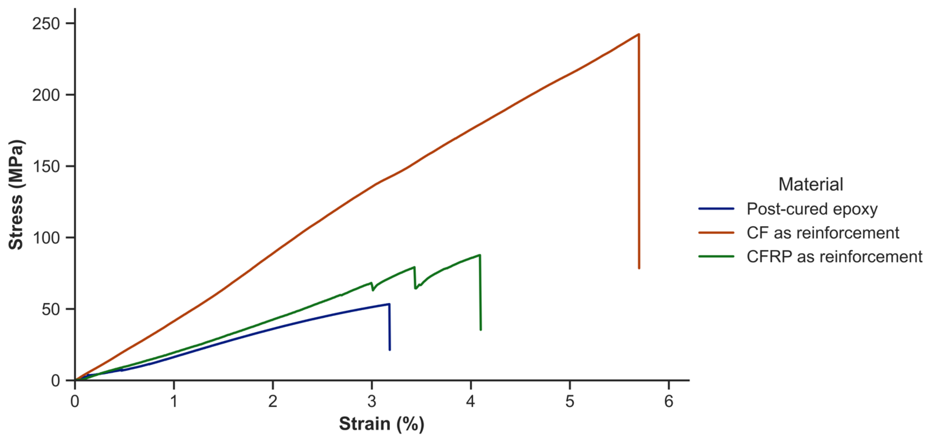
Figure 8 shows the stress–strain curves of the materials compared in
Table 9, including the epoxy resin, carbon fiber reinforced composites, and CFRP reinforced composites.
On the one hand,
Figure 8 exhibits that the area under the curve of the carbon fiber reinforced composites is much larger than that of the epoxy resin. The maximum stress is 365% higher, the strain at maximum stress is 63% higher, and the elastic modulus is 172% higher.
On the other hand, CFRP-reinforced composites display a larger area under the curve than epoxy resin and compared to it show 75% higher stress, 18% higher strain at maximum stress and comparable elastic modulus. In this case, even with a reinforcement mass fraction of 13%, which means a fiber volume fraction of only 8%, there is a substantial improvement in mechanical properties. This confirms the feasibility of using small amounts of reinforcement in the epoxy resin for its use in non-structural applications.
Comparing now the composites among each other, it is observed that those reinforced with carbon fibers are able to absorb a greater amount of energy. Thus, it is observed that these composites, compared to those reinforced with CFRP, show a 170% higher stress, a 37% higher strain at maximum stress, and a 163% higher elastic modulus.
Potential solutions to this inferior mechanical behavior include further separating the CFRP rods to increase the contact surface with the epoxy or modifying the epoxy to improve the wetting of the reinforcement.
The results obtained demonstrate the validity of using epoxy as a matrix and recycled composite material as reinforcement in a process for reintroducing composite materials that have reached their end-of-life back into the production cycle. Otherwise, these CFRPs would likely have been destined for incineration or landfilling. In the present case, the epoxy–epoxy bond exhibits favorable adhesion properties and does not require further treatments for improvement.
4. Conclusions
The process of manufacturing composites using discontinuous carbon fibers and mechanically recycled commercial CFRP in the form of rods was developed in this study.
The thermal characterization of the epoxy matrix was carried out to investigate the curing kinetics and the Tg. The chemical characterization of the epoxy matrix was also conducted to examine the chemical changes in both components, as well as after mixing, after curing for 24 h, and after post-curing. The findings from this analysis confirmed the observations made using DSC and the recommendations made by the manufacturer concerning the necessity of post-curing. The proposed post-curing was 8 h at 80 °C to achieve 99% curing of the resin and to increase the Tg (88 ± 1 °C), which resulted in greater crosslinking and higher resin stiffness.
A fractional factorial design (DOE method) was utilized to examine the effect of three chosen factors on the mechanical behavior of composites using discontinuous carbon fibers as reinforcement: LPP treatment, post-curing, and fiber length. By varying the values of each factor between high and low, the eight possible combinations were tested and the effect of each factor individually, as well as pair interactions and all factors together, were analyzed. Analysis of the experimental data using Yates’ algorithm revealed several general conclusions. Firstly, LPP treatment had a minimal impact on mechanical properties and tended to be unfavorable. Essentially, any combination of another factor with LPP treatment resulted in a decline in mechanical properties, except in the case of strain, which was enhanced when LPP treatment was accompanied by post-curing (up to 3.1%) or post-curing and long fiber (up to 7.5%). Secondly, the factors that most significantly improved mechanical behavior were post-curing in terms of stress and stiffness (89 MPa and 3.9 GPa, respectively), and fiber length in terms of strain at maximum stress (up to 5.6%). The optimal combination of factors, particularly considering stress, was found to be post-curing and fiber length (C x L). Therefore, this combination was selected as the most suitable for the manufacture of the composites, which led to achieving a maximum stress, stiffness, and strain at maximum stress of 237 MPa, 4.3 GPa, and 5.5%, respectively.
Finally, composites were manufactured using the same epoxy matrix but a commercially recycled CFRP mechanically in the form of rods. The epoxy–epoxy bond between the matrix and reinforcement leads to effective adhesion, making additional treatments unnecessary. While using mechanically recycled CFRP as a reinforcement is beneficial from a cost and weight perspective, the mechanical properties of the composite produced with carbon fibers are still superior to those of the CFRP, as demonstrated in this study with a 170% higher stress, a 37% higher strain at maximum stress, and a 163% higher stiffness. Potential solutions for future work may include further separating the CFRP rods to increase the contact surface with the epoxy or enhancing the wetting properties of the epoxy and reinforcement. While the results showed potential for improvement, they also illustrated the feasibility of the recycling process for CFRP and the manufacturing of composites using recycled CFRP.


