Article

Study on Mushy Zone Coefficient in Solidification Heat Transfer Mathematical Model of Thin Slab with High Casting Speed

1
College of Metallurgy and Energy, North China University of Science and Technology, Tangshan 063009, China
2
College of Mechanical Engineering, Tangshan Polytechnic College, Tangshan 063299, China
*
Authors to whom correspondence should be addressed.
Processes 2023, 11(11), 3108; https://doi.org/10.3390/pr11113108
Submission received: 4 October 2023 / Revised: 25 October 2023 / Accepted: 27 October 2023 / Published: 30 October 2023
(This article belongs to the Special Issue Renewable Energy and Green Metallurgy Technology)

Abstract

:
When the casting speed of the thin slab continuous caster is increased, the ratios of the solid and liquid phases in the solidification front of the molten steel in the mold change, which affects the thickness of the solidified shell. In order to accurately calculate the thickness of the solidified shell and determine the value range of the mushy zone coefficient suitable for the mathematical model of solidification heat transfer at high casting speed, this paper established the solidification heat transfer mathematical model in thin slab funnel mold, and the influence of different mushy zone coefficients on the accuracy of solidification heat transfer mathematical model was analyzed and compared with the actual solidified shell thickness. The results showed that, when the casting speed was increased to 4~6 m/min and the coefficient of the mush zone coefficient was 3 × 10⁸~9 × 10⁸ kg/(m3⋅s), the thickness of solidified shell calculated by the solidification heat transfer model was in good agreement with that measured in practice. The research in this paper provides an important reference for the establishment of the solidification heat transfer mathematical model at high casting speed in the future.

1. Introduction

In the process of continuous casting, the flow condition of molten steel in the mold, the temperature distribution and the growth of the initial solidification shell all have great influence on the quality of the slab. With the improvement of the computer computing performance and the development of commercial software, numerical simulation has become an important means to study the transmission behavior of the continuous casting process, in which finite volume software Fluent is widely used in the numerical simulation of physical phenomena related to molten steel flow in the continuous casting process.
The solidification process of molten steel is carried out in a temperature range (liquidus temperature to solidus temperature), which is macroscopically manifested as a solid–liquid two-phase zone—that is, a mushy zone [1,2]. The forming slab generally has a surface chill layer, a central equiaxed crystal region and a middle columnar crystal region. It can be seen that, in the solidification process, the mushy region consists of columnar crystals or (and) equiaxed crystals and a liquid phase group. Among them, some columnar crystals are interrupted by the flowing molten steel and move with the molten steel; the rest of the columnar crystals move with the solidified shell and grow forward, and the equiaxed crystals are deposited with the flow of the liquid steel or downward. Columnar crystals and equiaxed crystals can hinder the flow of molten steel in the mushy zone and then affect the heat transfer and solidification process of molten steel. Two methods are generally used to deal with the flow of molten steel in the mushy zone, namely the variable viscosity method and the Darcy source term method. Because the viscosity data of the mushy zone are not easy to obtain when using the variable viscosity method, the Darcy source term method is widely used. The dendrites in the mushy zone are regarded as porous media that move along the solidification front and are filled with the liquid phase and a fraction of the solid phase changes continuously by the Darcy source term method [3,4,5,6,7]. Among them, permeability is an important parameter to reflect the transmission performance of porous media, which can reflect the flow characteristics of the liquid phase with a certain momentum in porous media, mainly affected by the structural characteristics and physical properties of porous media [8,9]. Pfeiler et al. [10,11] calculated the permeability using the Blake–Kozeny law and considered that the permeability was a function of the primary dendrite spacing. The expression given by Beckermann et al. [12,13] also believed that the permeability is related to the primary dendrite spacing. However, most scholars [14,15,16] use the Carman–Kozeny equation to deal with permeability and regard permeability as a function of secondary dendrite spacing. The mushy zone coefficient (Amush) is a physical quantity related to permeability. For general fluid software such as Fluent, Open FOAM, COMSOL, etc., in the process of establishing the solidification heat transfer model, the Amush introduces a damping term into the porous medium model. The Amush has a great influence on the numerical calculation of the flow and solidification behavior of molten steel, but the correct expression of the Amush is rarely given in the literature. Most scholars ignore the effect of the mushy zone coefficient on the solidification heat transfer model and usually use the default value of 1 × 10⁵ kg/(m3⋅s) as the Amush, resulting in the calculation results being inconsistent with reality [17,18]. Some scholars, Refs. [19,20,21], use a smaller Amush, resulting in the calculation results of overheating dissipation too fast, the liquid surface is too cold and so on. Trindade et al. [22,23] adopted the default value of Fluent 1 × 10⁵ kg/(m3⋅s) as the Amush, resulting in the liquid phase ratio of the steel at the center of the mold outlet being lower than 1. Hietanen et al. [24,25] studied the effect of Amush at 1 × 10³~1 × 10⁷ kg/(m3⋅s) on the solidification of molten steel, and the results showed that, when the Amush value was low, the temperature of molten steel dropped too fast, which was inconsistent with reality. When the Amush was 1 × 10⁷ kg/(m3⋅s), the calculated results were more realistic. However, when the Amush is increased to 1.5 × 10⁷ kg/(m3⋅s), the calculation is difficult to converge. Wang Qiangqiang [26] pointed out that, when the Amush was 1 × 10⁵ kg/(m3⋅s), the molten steel temperature in the mold was mostly lower than the liquidus temperature, and there was almost no formed solidified shell near the impact zone of the narrow surface flow. It can be seen that it is very important to select the appropriate Amush for the understanding and grasp of the flow and solidification phenomenon of molten steel in the mold.
At present, with the increasing of the casting speed of the thin slab continuous casting caster, the range of Amush values satisfying the mathematical model of solidification heat transfer at high casting speed is worth discussing. Therefore, this study only considers the scope of application of Amush in the solidification process of thin slab continuous casting with high casting speed and focuses on studying the temperature field of molten steel in the mold and the law of solidified shell growth. Moreover, the thickness of the solidified shell is compared with that calculated by numerical simulation through actual measurement. The value range of Amush in the heat transfer solidification model with high casting speed is determined, which provides a theoretical basis and reference for industrial production.

2. Experiment and Simulation

2.1. Basic Assumptions

Based on the complex metallurgical physical phenomenon in the thin slab continuous casting mold, combined with the characteristics of the thin slab continuous casting process, the following basic assumptions are made about the flow of molten steel and solidification heat transfer in the funnel mold to simplify the calculation process [27,28]:
(1)
The flow process of molten steel is a viscous incompressible fluid, and the effects of the phase change, vibration, protective slag and solidification shrinkage are not considered.
(2)
The effects of the fluctuation of the mold meniscus, taper, phase transformation of Fe-C alloy, solidified shell shrinkage and vibration on solidification heat transfer are ignored.
(3)
The continuous casting process is regarded as a steady state, and the turbulent effect of molten steel is simulated by the low Reynolds number standard k-ε model.
(4)
The mushy zone is regarded as a porous medium, and the flow in the mushy zone obeys Darcy’s law.
(5)
The movement speed of the solidified shell is consistent with the casting speed.

2.2. Governing Equation

In this part, the enthalpy–porous medium method is used to deal with the flow, heat transfer and solidification of molten steel in a funnel mold. The differential equation for heat transfer control is shown in (1).
ρ C P d T d t + · ρ v H = · λ T + S h
Among them,
H = h r e f + T r e f T C p d T + β L N
Porosity is equal to the liquid phase volume fraction β, as shown in (3).
β = 0   ( T < T s ) T T s T l T s   ( T < T s ) 1   ( T > T l )
Formula: T l is the liquidus temperature, K; T s is the solidus temperature, K; S h is the heat source term, J/(m3⋅s); C p is the specific heat capacity, J/(kg · K); L N is the latent heat of the solidification, J/kg; the reference enthalpy is href with respect to the Tref; H is the total enthalpy of the system, J; β is the liquid phase volume fraction.
The liquidus temperature TL and solidus temperature TS of molten steel are calculated by the empirical Formulas (4) and (5).
TL = 1539 − 70w[%C] + 8w[%Si] + 5w[%Mn] + 30w[%P] − 25w[%S] + 4w[%Ni] − 1.5w[%Gr]
Ts = 1536 − 415.3w[%C] − 12.3w[%Si] − 6.8w[%Mn] − 124.5w[%P] − 183.9w[%S] − 4.3w[%Ni] − 1.4w[%Gr] − 4.1w[%Al]
Formula: w is the mass fraction, %.
The basic principle of the enthalpy–porous medium method is to regard the metal solid–liquid two-phase region as a porous medium and to characterize the proportion of the liquid phase in the unit by calculating the temperature of each unit. The sum of the proportion of the liquid phase in the two phases is between 0 and 1, and the porosity is different in each cell, so the fluid resistance settings are different [29].
The momentum and turbulent kinetic energy lost during the solidification of the fluid will be added to the momentum and turbulence equations in the form of source terms.
The source term to be added to the momentum equation is shown in Equation (6).
S m = 1 β 2 β 3 + ε A m u s h ( u u p )
The source term to be added in the turbulence equation is shown in Equation (7).
S q = 1 β 2 β 3 + ε A m u s h ( u u p )
Formula: u p is the casting speed, m/s; A m u s h   is the mushy zone coefficient, kg/(m3⋅s).
The size of the Amush will affect the flow in the two-phase region. To prevent the divisor from being 0, set the ε to 0.001.

2.3. Boundary Conditions and Physical Parameters

This section studies the solidification heat transfer process of molten steel in the mold. The main process parameters are as follows: grade of the steel is SS400, its main component is 0.18% ≤ C ≤ 0.20%, S ≤ 0.005% and P ≤ 0.018%, with a section (width × thickness) of 1520 × 90 mm2. Other assumptions are as follows:
(1)
The superheat of molten steel is 20 K, and the inlet temperature of molten steel is 1823 K, and it is kept constant.
(2)
Due to the good heat preservation effect of the liquid surface mold slag, the free liquid surface is set as the adiabatic condition, and the submerged entry nozzle (SEN) wall is also set as the adiabatic wall.
(3)
The temperature gradient perpendicular to the symmetric plane is zero.
(4)
The moving speed of a narrow face and wide face is consistent with the casting speed, which is given by Patch. The boundary heat flux of the mold area is given according to the real-time monitoring data of the actual production computer; that is, the boundary condition of the mold is defined by the second type of boundary condition of heat transfer.
The heat transfer and solidification of molten steel are simulated by the commercial software Fluent. The initial inlet velocity of the model was calculated according to the inner diameter of the SEN (80 mm), the casting speed and the size of the funnel mold. The numerical calculation method is used with the standard K-ε turbulence model, opening the energy equation and calculating in combination with the solidification and melting model. The superheat and specific heat of molten steel are added through the operation interface settings, and the heat flow is applied through the user-defined function. The hydrothermal physical properties of molten steel used in the simulation are shown in Table 1 [30]. It should be noted that, since the two-phase region is approximately treated as a porous medium, the heat transfer in the two-phase region can be approximately treated as the heat transfer in a porous medium.

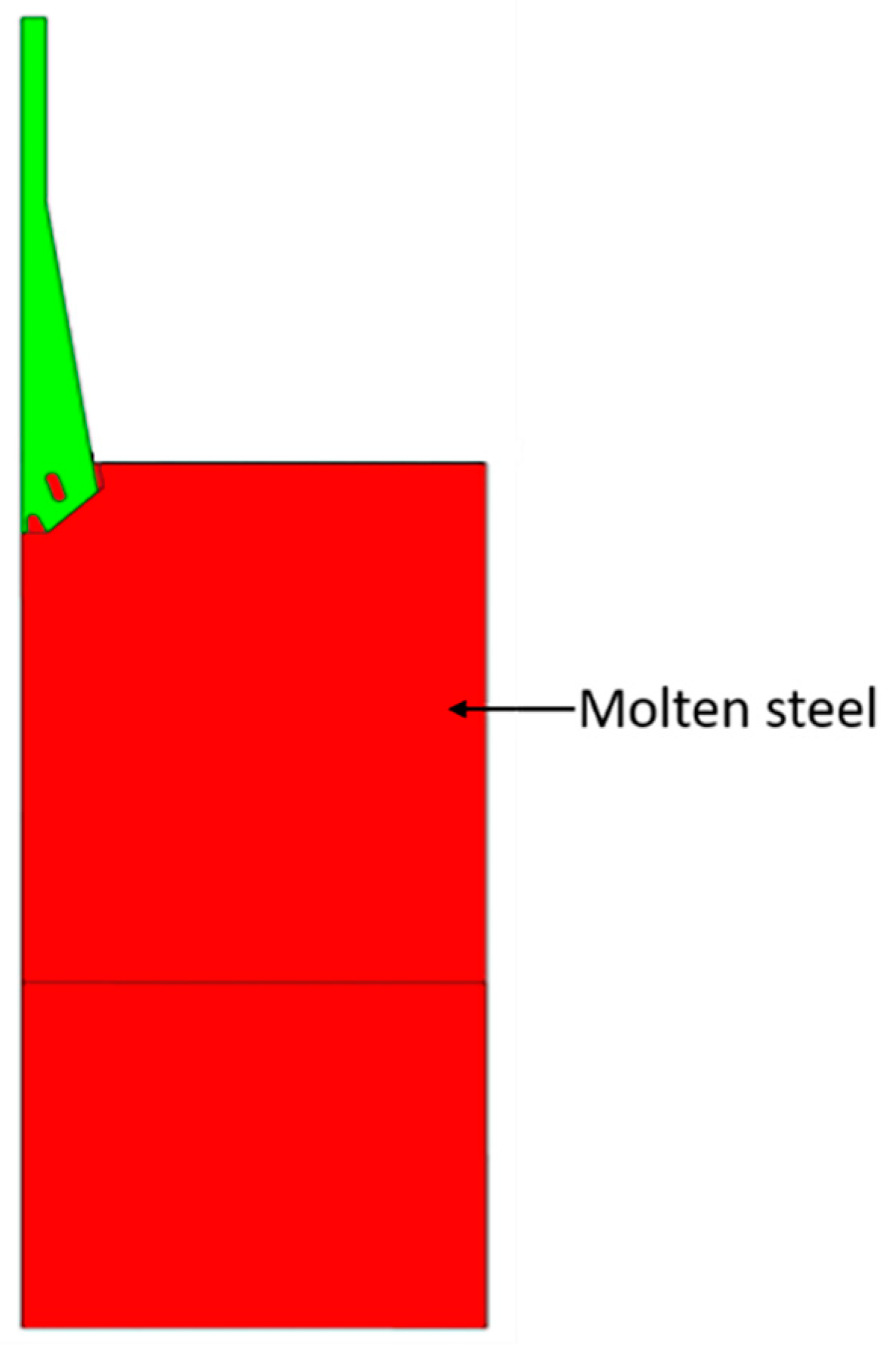
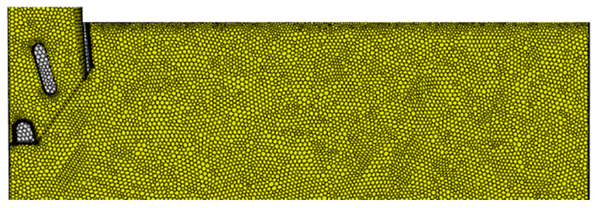
2.4. Grid and Computing Domain

The three-dimensional (3D) geometric model of two-phase flow 1/2 combined with a funnel mold and the SEN is shown in Figure 1. The fluid domain is molten steel.
The MESH module in ANSYS software is used to mesh the 3D geometric model of SEN and the funnel mold. Due to the complexity of the structure of the SEN and the funnel mold, the model adopts hexahedral nonstructural mesh division. In order to consider the accuracy of the calculation results and the stability of the calculation process, the mesh encryption process was carried out at the molten steel surface of the fluid domain in the mold, and the total number of the mesh was about 1.4 million. The reflux at the outlet of the mold seriously affects the calculation accuracy and convergence. After repeated trial and error, the length of the calculation domain of the mold was determined to be 2200 mm. The local grid division is shown in Figure 2.

2.5. Numerical Methods

Considering that there are many coupling models, the residual curve is prone to oscillations and difficult to converge, so the Couple algorithm is used for transient calculation, where the time step gradually increases from 0.001 s to 0.005 s. The momentum equation adopts the second-order upwind discrete scheme. Convergence is considered when the convergence standard is set as ≤1.0 × 10⁻⁵, and the ratio between the difference of inlet and outlet flow and the value of inlet flow is ≤1%.

2.6. Test Scheme

The expression of Amush is shown in Equation (8).
A m u s h = u l K
Formula: K is the permeability; u l is the laminar viscosity, Pa·s.
In the solidification process of molten steel, many scholars and experts have obtained different permeability expressions through experiments. The expression given by Beckermann shows that the permeability is related to the primary dendrite spacing, as shown in Equation (9).
K = 6 × 10 4 λ 1 2 β 3 ( 1 β ) 2
Formula: λ1 is the primary dendrite spacing size, m.
Figure 3 shows the measured relationship between the primary dendrite spacing of a continuous casting slab and the thickness of the slab. When β = 0.3, the variation rule of Amush with the thickness of the slab can be obtained. From the surface of the slab to the thickness center, Amush gradually decreases from 3.1 × 10⁸ kg/(m3⋅s) to 1.7 × 10⁸ kg/(m3⋅s).
Previous studies have found that permeability is closely related to the secondary dendrite spacing and solidification state of a continuous casting slab, as shown in Equation (10).
K = λ 2 2 u l β 3 180 1 β 2
Formula: λ2 is the secondary dendrite spacing, m.
Due to the selective crystallization in the solidification process, some components are enriched in the liquid phase, which affects the liquidus temperature. Therefore, temperature and solute redistribution need to be considered in order to accurately predict the solidification process, and permeability is an important parameter for accurately predicting tissue properties [31]. In order to make the calculation results of the solidification heat transfer model of thin slabs with high casting speed more accurate, based on previous studies, this paper set six groups of parameters for the Amush value in the solidification heat transfer model of thin slabs with high casting speed, as shown in Table 2. The influence of the Amush value on the solidification heat transfer model was quantitatively studied. The paper provides a reference for the coefficient Amush of the mushy zone to establish the solidification heat transfer model of thin slabs with high casting speed in the future.

3. Results and Discussion

3.1. Description of the Effect of Amush on Heat Transfer and Solidification of Molten Steel

As can be seen from Table 3, when the Amush is set to a smaller value of 1 × 10⁵ kg/(m3⋅s), the liquid-phase fraction of the molten steel near the liquid level at the SEN outlet is about 0.8, and between the solidification front of the narrow surface of the mold and the molten steel, blue bars are obviously visible from the mold liquid level to the SEN outlet, indicating that the mushy zone is large and there is almost no formed solidified shell on the narrow face.
When the Amush is 1 × 10⁷ kg/(m3⋅s), a large part of the region with a low liquid fraction near the liquid surface of the mold and SEN outlet still exists, but the solidified shell thickness gradually increases from below the meniscus, and the solidified shell also begins to solidify on the impact path of the flow stream, but the mushy zone is still obvious. When the Amush is 1 × 10⁸ kg/(m3⋅s), the simulation results are similar to those when Amush is 1 × 10⁷ kg/(m3⋅s), but the mushy zone is still clearly visible in the lower part. When the Amush is ≥3 × 10⁸ kg/(m3⋅s), the lower liquid fraction region disappears, but when the Amush is 3 × 10⁸ kg/(m3⋅s), the solidified shell thickness is not obvious in the upper part of the mold, and the solidified shell formation is thin, but the mushy zone is significantly reduced. When the Amush is 9 × 10⁸ kg/(m3⋅s), the thickness of the solidified shell starts from the liquid side down, and the thickness increases obviously. In order to further determine the numerical range of the Amush, the numerical simulation results were compared with the actual measurement of solidified shell thickness, and the value of the Amush was determined.

3.2. Amush Parameter Determination and Heat Transfer Solidification Model

3.2.1. Election of Amush Parameters

At present, there are three methods to determine the thickness of a solidified shell: namely, the empirical method, the heat balance method and the test method. Due to the restriction conditions of the empirical method and heat balance method, such as open casting, protective casting, molten steel composition, liquidus temperature and solid-phase temperature, they have great influence on the thickness of a solidified shell. At present, the test determination method should be widely used, such as “punching and draining liquid method”, “nail method”, “trace method” and other methods, but these methods are difficult to measure, and the measurement accuracy is relatively low. In recent years, the method of measuring solidified shell thickness using the test method has developed rapidly, and the method is simple and has high precision. Therefore, this part uses the test method to measure the thickness of the solidified shell—that is, using the solidified shell that is leaked in the production process, cutting the solidified shell along different heights and then measuring the average thickness of each position.
In this part, a continuous casting slab with a cross-section (width × thickness) of 1520 × 90 mm2, SEN immerse depth of 160 mm and casting speed of 5 m/min was cut and measured. The measuring positions were at one-fourth of the width of the solidified shell and at the middle of the narrow surface along the thickness, respectively. The distance from the liquid surface of the mold was 0.3 m, 0.7 m and 0.9 m. Then, the thickness of the solidified shell was measured at the symmetric position of the outer arc side and inner arc side, each position was measured three times and the average value of the thickness data was taken. The measurement process is shown in Figure 4.
The thickness of the solidified shell at the three measuring points on the narrow surface was about 4.2 mm, 6.9 mm and 10.2 mm from the liquid side down. The thickness of the wide solidified shell was about 4.0 mm, 8.2 mm and 10.6 mm in turn. As can be seen in Figure 4, no matter the narrow face or the wide face, the position of the measuring point from the liquid level down to the first measuring point and the third measuring point were wrapped by three solidified shell thickness curves calculated by numerical simulation with Amush values of D, E and F, followed by C, and A and B being the worst. The second measurement point was in poor agreement with the numerical simulation calculation of the solidified shell thickness, because the measurement point was located at the impact position of the main jet and the turbulent flow area near the main jet, and the formation of the solidified shell thickness had great instability. In summary, when the value of Amush ranges from 3 × 10⁸ to 9 × 10⁸ kg/(m3⋅s), the solidified shell thickness calculated by the mathematical model is more accurate. Therefore, when calculating the solidification mathematical model in this section, the value of the Amush was 6 × 10⁸ kg/(m3⋅s).

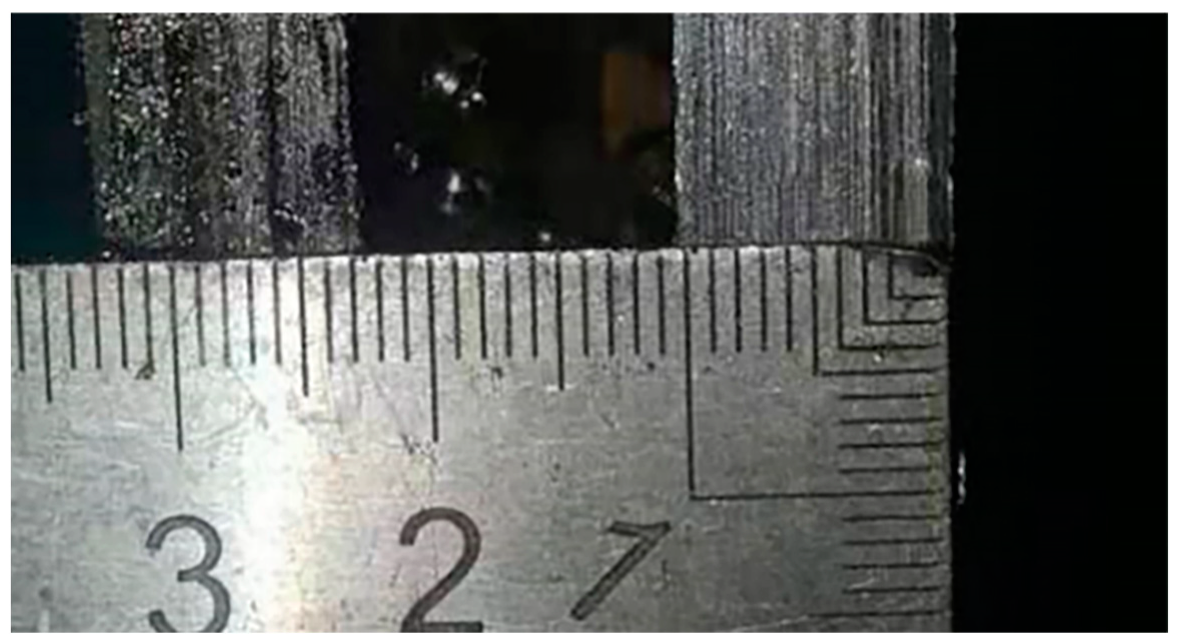
3.2.2. Verification of the Heat Transfer Solidification Model

According to the curve of the solidified shell thickness calculated when the value of Amush is 6 × 10⁸ kg/(m3⋅s), it can be seen that the solidified shell thickness shows a gradual increasing trend along the mold height direction, which can be said to be linear growth, and the solidified shell thickness reaches about 14 mm at the outlet position. However, as can be seen from the narrow face comparison diagram in Figure 5a, the growth rate of the solidified shell thickness decreased significantly at a distance of 600~800 mm from the meniscus of the mold, and a turning point appeared. The thickness of the solidified shell was only about 5.2 mm at the thinnest point, and then, the solidified shell thickness began to increase. Both the measured values and the simulated values indicated that the high-speed jet in the mold impaction on the narrow surface and the probability of steel leakage and slag inclusion was greater there. The reason is that there is a large temperature gradient and intense heat exchange at and near the impact point of the high-speed molten steel flow, and the strong scour effect of the high-speed molten steel flow makes heat replenishment there in time and the temperature is high, resulting in a growth lag of the solidified shell. The width face comparison diagram of the mold shows that the thickness of the solidified shell fluctuates greatly in the area of about 400~900 mm, but the overall growth is relatively stable. The reason is that the molten steel flowing out of the SEN outlet at high speed is very active in the flow path area, and because of the wide and thin section of the mold, the heat replenishment of the wide surface solidified shell is timely, resulting in slow solidification of the molten steel and a thin solidified shell. The flow of the molten steel in the center of the vortex is poor, and the temperature is low, which leads to the thickness of the solidified shell. The measurement results at 0.7 m away from the meniscus are not in good agreement with the mathematical simulation results, because the molten steel flow here is disordered, and there is no obvious rule. On the whole, the simulated calculation of the solidified shell thickness in this study is basically consistent with the actual measurement of the solidified shell thickness, which indicates that the solidification mathematical model established in this study has high reliability.

4. Conclusions

By developing a 3D solidification heat transfer mathematical model of a thin slab continuous casting mold, the effects of the mushy zone coefficient Amush on the flow, heat transfer and solidification process of molten steel in the two-phase zone at high casting speed were analyzed, and the thickness of the solidified shell was compared with that of an actual thin slab. We came to the following conclusions:
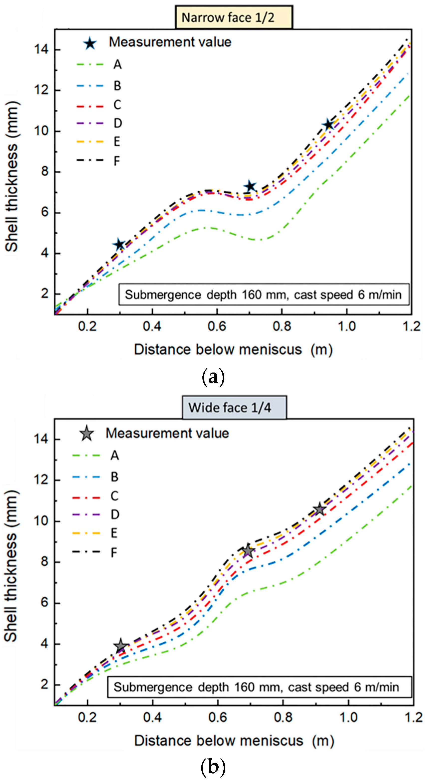
  • The smaller the mushy zone coefficient is, the higher the liquid–solid-phase ratio of steel near the liquid level, which is inconsistent with the actual situation. The larger the mushy zone between the solid and liquid in the front of the solidified shell, the thinner the solidified shell. The larger the mushy zone coefficient is, the lower the solid-phase ratio near the liquid surface, and the smaller the mushy zone area is, the thicker the solidified shell.
  • The mushy zone coefficient of 3 × 10⁸~9 × 10⁸ kg/(m3⋅s) can reliably reveal the actual solidification phenomenon in the mold of thin slab continuous casting at high casting speed.

Author Contributions

All authors contributed to the study’s conception and design. Material preparation, review and editing were performed by Z.D., Y.X., L.Z. and S.W. The first draft of the manuscript was written by Z.D. All authors commented on previous versions of the manuscript. All authors have read and agreed to the published version of the manuscript.

Funding

This research received no external funding.

Institutional Review Board Statement

Not applicable.

Data Availability Statement

Data can be obtained from the corresponding author upon reasonable request.

Conflicts of Interest

The authors declare no conflict of interest.

References

  1. Xuan, M.; Chen, M. Numerical investigation for the influence of turbulent heat transfer of mushy zone on shell growth in the slab mold: Casting and solidification. ISIJ Int. 2022, 62, 142–148. [Google Scholar] [CrossRef]
  2. Ghaemifar, S.; Mirzadeh, H. Refinement of banded structure via thermal cycling and its effects on mechanical properties of dual phase steel. Steel Res. Int. 2018, 89, 1700531. [Google Scholar] [CrossRef]
  3. Fujisaki, K. Magnetohydrodynamic solidification calculation in Darcy flow. IEEE Trans. Magn. 2003, 39, 3541. [Google Scholar] [CrossRef]
  4. Sun, H.B.; Zhang, J.Q. Study on the macrosegregation behavior for the bloom continuous casting: Model development and validation. Metall. Mater. Trans. 2014, 45, 1133. [Google Scholar] [CrossRef]
  5. Masud, A.; Hughes, T.J.R. A stabilized mixed finite element method for darcy flow. Comput. Methods Appl. Mech. Eng. 2002, 191, 4341–4370. [Google Scholar] [CrossRef]
  6. To, V.T.; To, Q.D.; Monchiet, V. On the Inertia Effects on the Darcy Law: Numerical Implementation and Confrontation of Micromechanics-Based Approaches. Transp. Porous Media 2016, 111, 171–191. [Google Scholar] [CrossRef]
  7. Bernardi, C.; Maarouf, S.; Yakoubi, D. Spectral discretization of darcy’s equations coupled with the heat equation. IMA J. Numer. Anal. 2015, 36, 1193–1216. [Google Scholar] [CrossRef]
  8. Li, H.M.; Liang, Y.F.; Chen, J.F.; Li, H.G.; Chen, X.Q. Relationship between pore structural characteristics and physical-mechanical properties of sandstone in shendong mining area. J. Henan Polytech. Univ. 2018, 37, 9–16. [Google Scholar]
  9. Kumar, S.S.; Rubio, E.J.; Noor-A-Alam, M.; Martinez, G.; Manandhar, S.; Shutthanandan, V. Structure, morphology, and optical properties of amorphous and nanocrystalline gallium oxide thin films. J. Phys. Chem. C 2013, 117, 4194–4200. [Google Scholar] [CrossRef]
  10. Pfeiler, C.; Thomas, B.G.; Wu, M. Solidification and particleentrapment during continuous casting of steel. Steel Res. Int. 2008, 79, 599–607. [Google Scholar] [CrossRef]
  11. Pacella, H.E.; Eash, H.J.; Frankowski, B.J.; Federspiel, W.J. Darcy permeability of hollow fiber bundles used in blood oxygenation devices. J. Membr. Sci. 2011, 382, 238–242. [Google Scholar] [CrossRef] [PubMed]
  12. Gu, J.P.; Beckermann, C. Simulation of convection and macroseg-regation in a large steel ingot. Metall. Mater. Trans. A 1999, 30, 1357–1366. [Google Scholar] [CrossRef]
  13. Aboutalebi, M.R.; Guthrie, R.I.L.; Seyedein, S.H. Mathematical modeling of coupled turbulent flotw and solidification in a single belt caster with electromagnetic brake. Appl. Math. Model. 2007, 31, 1671–1689. [Google Scholar] [CrossRef]
  14. Madhani, S.P.; D’Aloiso, B.D.; Frankowski, B.; Federspiel, W.J. Darcy permeability of hollow fiber membrane bundles made from membrana polymethylpentene fibers used in respiratory assist devices. Asaio J. 2016, 62, 329–331. [Google Scholar] [CrossRef]
  15. Valdes-Parada, F.J.; Ochoa-Tapia, J.A.; Alvarez-Ramirez, J. Validity of the permeability carman–kozeny equation: A volume averaging approach. Phys. A Stat. Mech. Appl. 2009, 388, 789–798. [Google Scholar] [CrossRef]
  16. Costa, A. Permeability-porosity relationship: A reexamination of the kozeny-carman equation based on a fractal pore-space geometry assumption. Geophys. Res. Lett. 2006, 33, 5134. [Google Scholar] [CrossRef]
  17. Ceretani, A.N.; Tarzia, D.A. Determination of one unknown thermal coefficient through a mushy zone model with a convective overspecified boundary condition. Math. Probl. Eng. 2015, 21, 637852. [Google Scholar] [CrossRef]
  18. Peng, P.; Lu, L.; Zheng, W.; Wang, J. Macrosegregation and channel segregation formation of faceted mushy zone in solidification of sn-ni hypereutectic alloy in a temperature gradient. Mater. Chem. Phys. 2021, 264, 124447. [Google Scholar] [CrossRef]
  19. Sun, H.B.; Zhang, J.Q. Effect of feeding modes of molten steel on the mould metallurgical behavior for round bloom casting. ISIJ Int. 2011, 51, 1657. [Google Scholar] [CrossRef]
  20. He, M.L.; Wang, N.; Chen, M.; Xuan, M. Physical and numerical simulation of the fluid flow and temperature distribution in bloom continuous casting mold. Steel Res. Int. 2017, 88, 1600447. [Google Scholar] [CrossRef]
  21. Trindade, L.B.; Nadalon, J.E.A.; Contini, A.C.; Barroso, R.C. Modeling of solidification in continuous casting round billet with mold electromagnetic stirring (M-EMS). Steel Res. Int. 2017, 88, 1600319. [Google Scholar] [CrossRef]
  22. Mohamed, F.; Eames, P.C. Numerical investigation of the influence of mushy zone parameter Amush on heat transfer characteristics in vertically and horizontally oriented thermal energy storage systems. Appl. Therm. Eng. 2019, 151, 90–99. [Google Scholar]
  23. Won, Y.M.; Thomas, B.G. Simple model of microsegregation during solidification of steels. Metall. Mater. Trans. A 2001, 32, 1755–1767. [Google Scholar] [CrossRef]
  24. Hietanen, P.T.; Louhenkilpi, S.; Yu, S. Investigation of solidification, heat transfer and fluid flow in continuous casting of steel using an advanced modeling approach. Steel Res. Int. 2017, 88, 1600355. [Google Scholar] [CrossRef]
  25. Ji, Y.; Tang, H.Y.; Lan, P.; Shang, C.; Zhang, J. Effect of dendritic morphology and central segregation of billet castings on the microstructure and mechanical property of hot-rolled wire rods. Steel Res. Int. 2017, 88, 1600426. [Google Scholar] [CrossRef]
  26. Wang, Q.Q. Stundy on the Multiphase Flow, Heat Transfer and Solidification, Motion and Entrapment of Inclusions During Continuous Casting; University of Science and Technology: Beijing, China, 2016. [Google Scholar]
  27. Yue, Q.; Zhou, L.; Wang, J.J. Numerical simulation of the coupling of molten Steel flow, heat transfer and solidification in a slab mold with Double transverse Stability Electromagnetic Braking. J. Process Eng. 2011, 11, 187–192. [Google Scholar]
  28. Zhang, L.M.; Xiao, P.C.; Wang, Y.; Liu, Z.X.; Zhu, L.G. Effect of EMBr on flow in slab continuous casting mold and industrial experiment of nail dipping measurement. Metals 2023, 13, 167. [Google Scholar] [CrossRef]
  29. Yang, C.L. Simulation Research on Solidification Heat Transfer and Film Formation of Protective Slag in Continuous Casting Mold; Chongqing University: Chongqing, China, 2018. [Google Scholar]
  30. Alizadeh, M. Correlation between the continuous casting parameters and secondary dendrite arm spacing in the mold region. Mater. Lett. 2013, 91, 146–149. [Google Scholar] [CrossRef]
  31. Minakawa, S.; Samarasekera, I.V.; Weinberg, F. Centerline porosityin plate castings. Metall. Trans. B 1985, 16, 823–829. [Google Scholar] [CrossRef]
Figure 1. Three-dimensional geometric model of mold.
Processes 11 03108 g001
Figure 2. Local mesh division of the funnel mold geometric model.
Processes 11 03108 g002
Figure 3. The change of primary dendrite spacing and Amush thickness in the casting slab: (a) primary dendrite spacing; (b) Amush value.
Processes 11 03108 g003
Figure 4. Measurement of the solidified shell of molten steel leakage.
Processes 11 03108 g004
Figure 5. Comparison between the calculated value of the solidified shell thickness and the measured value: (a) thickness of the narrow face solidified shell; (b) thickness of the wide face solidified shell.
Processes 11 03108 g005
Table 1. Related parameters for the solidification heat transfer model.
Thermophysical Property Parameters Value
Molten steel density7020 (kg/m3)
Molten steel viscosity0.0064 (Pa⋅s)
Casting speed(4, 5, 6) m/min
Initial value of velocity (casting speed: (4, 5, 6) m/min)(1.82, 2.27, 2.72) m/s
Turbulent kinetic energy (casting speed: (4, 5, 6) m/min)(6.32, 9.31, 1.28) m2/s2
Turbulent dissipation rate (casting speed: (4, 5, 6) m/min)1.48, 2.63, 4.24
Superheat of molten steel20 K
Solidus temperature (TS)1763 K
Liquidus temperature (TL)1803 K
Specific Heat Capacity (Cp)680 J/(kg · K)
Latent heat of solidification (LN)270,000 J/kg
Wide surface heat flux ( q ¯ w :   4 m/min, 5 m/min, 6 m/min)(2.0, 2.1, 2.2) × 106 W/m2
Narrow surface heat flux ( q ¯ n : 4 m/min, 5 m/min, 6 m/min)(1.8, 1.9, 2.0) × 106 W/m2
Specific heat capacity (CW)4.2 × 10³ J/(kg · K)
Table 2. Amush value ranges.
NumberAmush (kg/( m 3 · s))
A1 × 105
B1 × 107
C1 × 108
D3 × 108
E6 × 108
F9 × 108
Table 3. Picture of the solid- and liquid-phase distribution in the middle surface of the funnel mold thickness. Unit: kg/(m3⋅s).
A m u s h A: 1 × 10⁵B: 1 × 10⁷C: 1 × 10⁸Processes 11 03108 i004
Picture of solid- and liquid-phase distributionProcesses 11 03108 i001Processes 11 03108 i002Processes 11 03108 i003
A m u s h D: 3 × 10⁸E: 6 × 10⁸F: 9 × 10⁸
Picture of solid and liquid phase distributionProcesses 11 03108 i005Processes 11 03108 i006Processes 11 03108 i007
Disclaimer/Publisher’s Note: The statements, opinions and data contained in all publications are solely those of the individual author(s) and contributor(s) and not of MDPI and/or the editor(s). MDPI and/or the editor(s) disclaim responsibility for any injury to people or property resulting from any ideas, methods, instructions or products referred to in the content.

