Article

A CFD Investigation on the Aerosol Drug Delivery in the Mouth–Throat Airway Using a Pressurized Metered-Dose Inhaler Device

1
Department of Chemical Engineering, Lakehead University, 955 Oliver Road, Thunder Bay, ON P7B 5E1, Canada
2
School of Graphic Communications Management, Toronto Metropolitan University, Toronto, ON M5B 2K3, Canada
*
Author to whom correspondence should be addressed.
Processes 2022, 10(7), 1230; https://doi.org/10.3390/pr10071230
Submission received: 18 May 2022 / Revised: 13 June 2022 / Accepted: 16 June 2022 / Published: 21 June 2022
(This article belongs to the Special Issue Complex Fluid Dynamics Modeling and Simulation)

Abstract

:
Inhalation therapy involving a pressurized metered-dose inhaler (pMDI) is one of the most commonly used and effective treatment methods for patients with asthma. The purpose of this study was to develop a computational fluid dynamics (CFD) model to characterize aerosol flow issued from a pMDI into a simulated mouth–throat geometry. The effects of air flow rate and cone angle were analyzed in detail. The behaviour of the multiphase flow initiated at the inhaler actuation nozzle and extended through the mouth–throat airway was simulated based on the Eulerian-Lagrangian discrete phase model, with the k-ω model applied for turbulency. We validated our model against published experimental measurements and cover the hydrodynamic aspect of the study. The recirculation we observed at the 90° bend inside the mouth–throat airway resulted in the selective retention of larger diameter particles, and the fluid flow patterns were correlated with drug deposition behaviour. Enhancing air flow rates up to three times reduced the aerodynamic particle diameters to 20%. We also observed that, as cone angle increased, mouth deposition increased; an 8° cone angle was the best angle for the lowest mouth–throat deposition.

1. Introduction

Pulmonary drug delivery is of paramount importance to the pharmaceutical industry because it allows the delivery of low bioavailability drugs to a large surface area of the lungs. The pressurized metered-dose inhaler (pMDI) has been the primary choice for the therapeutic management of asthma since the late 1950s [1]. Despite recent improvements in respiratory drug delivery treatment, less than 30% of a dose reaches a patient’s lungs [2]. The rest is either deposited in the valve stem, nozzle, valved holding chamber (if present), or within the mouth–throat airway [3], all of which are possible obstructions to airflow. Studies show that patients experience difficulty coordinating the timing between the actuation of the inhaler and the inhalation; this is due to a lack of understanding of the device’s technology and mechanics [4,5]. Both drug formulation (in suspension or solution base) and proper device design are essential for the effective treatment of respiratory conditions. Since drug deposition is unevenly distributed within the lungs [6,7], drug delivery must be better targeted to generate and deliver fine aerosols into the lungs [8].
Pharmaceutical aerosol movement is via a multiphase flow, consisting of a continuous phase (inhaled air) and a discrete drug phase (particles or droplets containing an active therapeutic agent. The pharmaceutical aerosol size or respirable size ranges from nano to micrometer. An aerosol size less than 7 µm is ideal for preventing inertial impacts along its path to the lungs and sizes ranging from 2 to 3 µm are required to reach the peripheral lung for effective treatment [8,9]. Some of the important factors that affect aerosol deposition are the inhaler’s properties, such as the nozzle’s shape [9,10,11,12], and the aerosol particle distribution affected by flow rate, spray actuation time, airflow obstruction, cone angle, and spray plume cloud [8,13,14,15].
Experimental lung-drug delivery setups are expensive and limited by the complex geometry of the respiratory tract, measurement inaccuracies due to the spatial and temporal resolutions of imaging techniques such as laser diffraction, and the danger of exposing the patient to radiation in in- vivo experiments [5,16]. These limitations can be overcome using numerical computation that would allow the study of the drug particle’s delivery with high accuracy. Since the 1990s, pharmaceutical industries have concentrated on drug delivery studies involving numerical modelling strategies using computational fluid dynamics (CFD) for an in-depth analysis [17]. CFD simulations can address physical factors (such as velocity) related to both particles and airflow, with illustrations of contours, flow patterns, and particle track plots. Vinchurkar et al. [18] illustrated the utility of a CFD model while evaluating the performance of the Andersen cascade impactor (ACI) for particle size distribution and deposition efficiency. The authors showed the benefits and accuracy of the CFD approach through the particle size measurements and found the results to vary within a 5–10% error of the experiments [18].
The mouth–throat airway’s geometry and inhalation flow rate affect the flow structure, which subsequently affects an aerosol’s lung deposition. Zhang et al. [13] conducted a CFD study to propose a modified idealized induction port (IP) with a curved 90° bend. They observed that with less flow circulation near the curved bend, drug delivery to the lung was enhanced. When they used the near-wall corrections of the turbulent kinetic velocity in their simulations, the deposition of particles in the proposed idealized mouth–throat geometry showed good agreement with in vitro results [13]. These corrections were necessary to account for complex flow characteristics (secondary flow regions and circulated areas) in the proposed mouth–throat airway. A CFD analysis by Oliveira et al. [1] showed that stable airflow at the spacer’s outlet reduced the recirculation area and provided better drug deposition to the lungs. In another CFD study, Oliveira et al. [19] explored the characterization of the pMDI aerosol plume. They characterized the spray plume as a transient jet and found that drug aerosolization was completed in the first 0.1 s of the spray duration [19]. The impact of flow rate on spray plume behaviour and particle deposition was then investigated in their study. Buchmann et al. [20] also studied the effect of airflow rate on the development of the aerosol plume. They observed an axisymmetric plume pattern at the zero-flow rate and a downward deflected plume due to uneven shear [20].
To specifically study the impact of flow rate on particle deposition, Cheng et al. [21] designed an experiment based on three different flow rates (15, 30, and 60 L/min) on different replicas of the United States Pharmacopeia (USP) IP geometries. They showed that high diameter particles (5–26 µm) sedimented as the flow rate increased and developed a correlation for deposition efficiency using the Stokes number, which was calculated based on the mouth-inlet velocity and minimum particle diameter [21]. Bass and Longest [22] used a CFD study to investigate the dependence of particle deposition in the mouth–throat pathway on airflow and turbulence within the system. At higher flow rates and consequently high Reynolds numbers, the deposition fraction of fine particles (<4 µm) was found to be most sensitive to turbulence; therefore, fine particles were carried by the air stream, but larger particles (>5 µm) were deposited in the mouth–throat pathway [22]. This study also highlighted the importance of aerosol plumes in IP with a constant cone angle (particle entrance angle) [22]. Koullapis et al. [23] presented a benchmark case for the validation of computational tools intended for an upper zone deposition. Particle deposition increased with particle sizes for all the three flow rates tested (15, 30, and 60 L/min), and particles smaller than 5 µm were unaffected by flow rates. The dominant deposition mechanism in the mouth–throat airway was found to be inertial impaction [23].
Duke et al. [24] demonstrated in vitro that approximately 20% of the total cumulative dose was delivered to the lung in the first 0.1 s of the spray. They noticed a rapid drop in drug mass fraction in the upper airway due to the drug deposition in that area [24]. They concluded that the leading particles at the edge of the aerosol plume encounter a drag force against still air and thus experience less particle/particle interactions in comparison with the particles that follow [24].
Ganderton et al. [25] experimentally studied the importance of nozzle diameters. They observed a significant increase in fine particle dose when the actuator nozzle diameter was decreased from 0.42 to 0.22 mm [25]. Several other studies confirmed that a small nozzle diameter leads to smaller drug particles [16,26,27] considering the impact of varying cone angles from 0° to 40° along with different flow rates and different mouthpiece diameters on inhaler efficiency. They showed that MDI efficiency increased to around 10% when the cone angle increased from 0° to 20°. They also showed the flow rate and mouthpiece diameters do not impact the particle penetration efficiency through the upper airway. Buchmann et al. [20] designed an experiment to accurately characterize the spray plume. They investigated the impact of the air co-flow on the spray tip penetration, tip velocity, and cone angle [20]. They reported that the air co-flow has minimal effect on the tip penetration and spray velocity, despite impacting the width and angle of the spray plume [20].
Gavtash et al. [28] used a high-speed camera to capture the spray near the orifice. They showed that the spray velocity (which is affected by the flow regime and nozzle diameter) is one of the main sources of particle fragmentation [28]. They also showed the impact of the cone angle as a time-dependent spray characteristic on the particle size distribution [28]. By including the upper airway geometry, Yousefi et al. [29] found that the larger spray cone angle at the lower flow rates (i.e., 15 L/min) caused a higher particle deposition in the pharynx zone. Chen et al. [30] examined different nozzle designs (i.e., cone, curved cone, flat, and curved flat) and found that the curved-cone nozzle shape produced a narrower plume since this nozzle design generated extra pressure on the initial plume after actuation. However, they found that different drug formulations also affected the aerosol plume shape [30].
All the above-mentioned studies discussed major parameters affecting particle deposition and spray plume; however, they failed to adequately analyze the effects of flow rate and cone angle on the particle deposition and spray plume. Our study exploited the exceptional capabilities of CFD to address the effects of flow rate and actuation cone angle on the particle size distribution, the mouth–throat airway deposition, and aerosol behaviour during the actuation of pMDI drug deposition in the mouth–throat airway. The behaviour of air streamlines around the 90° bend and the effect of higher flow rates on recirculation was studied. Aerosol’s particle tracking and residence time were also studied by observing the flow streamlines and turbulent kinetic energy changes through the actuation time. Our study was validated by the experimental data of Lewis et al. [31] and covered the numerical aspect of their research.

2. CFD Model Development

The 3D model geometry and meshing were performed, respectively, using the Geometry and Mesh modules in ANSYS® Workbench (ANSYS® release 2019 R1 v193) [32].

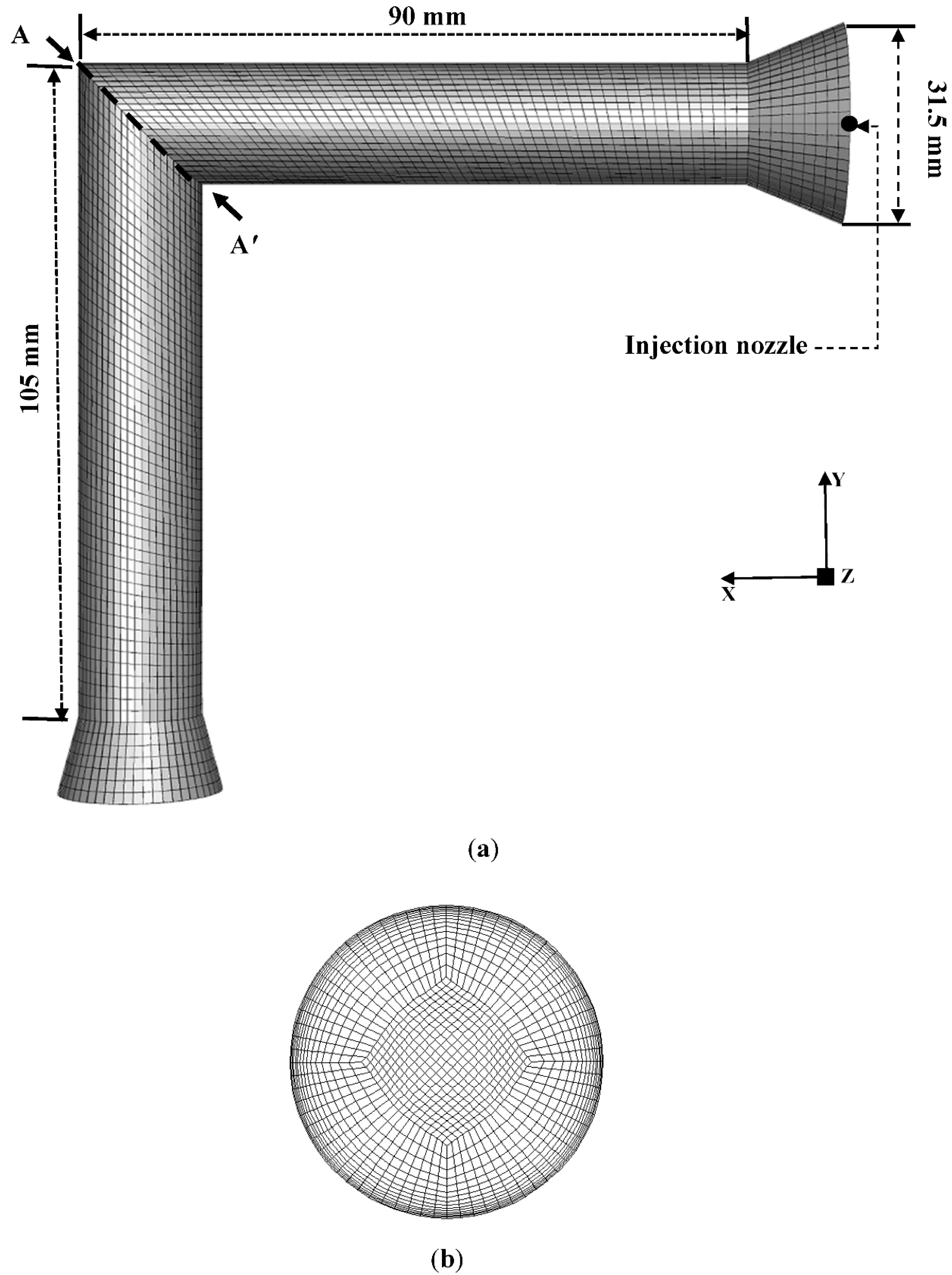
2.1. Geometry and Material

Figure 1 shows the schematic of the mouth–throat airway through side and cross-section views with dimensions and mesh. The mouth–throat airway had a 90° bend with the inner and outer diameters of 19 and 31.5 mm, respectively. The injection nozzle was positioned at the center of the outer circle (Figure 1a). Modeling the detail of the mechanical design of the pMDI’s canister due to complexity up to the nozzle was not considered in this work.
The effect of flow rate and cone angle (Table 1) were determined using beclomethasone dipropionate (BDP) particles with a density of 1300 kg/m3 and viscosity of 1.75 × 10⁻⁵ kg/m.s. The factory-adjusted constant flow rate of 28.3 L/min [33] was adopted to analyze a realistic device and understand the effects of small changes in flow rates.

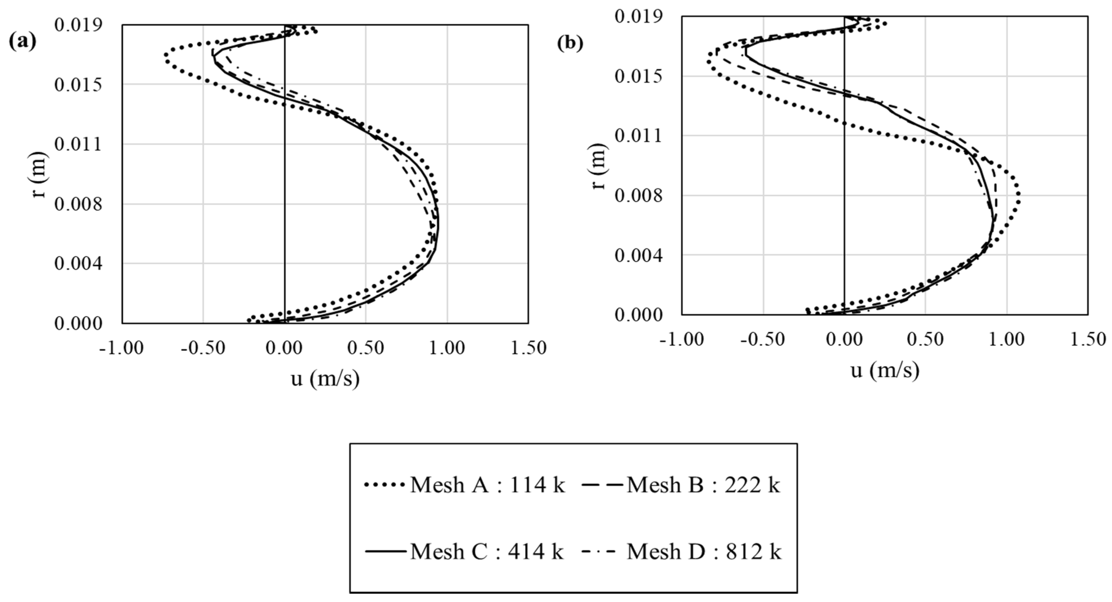
2.2. Mesh Independency Study

Grid convergence was tested for various element sizes and refinements (Table 2). Meshes consisting of ~114 k, 222 k, 414 k, and 812 k cells were applied for our mesh independency study. The tangential air velocity profiles were compared along the most turbulent area with circulation flows, line AA′ (Figure 1), in the mouth–throat airway geometry at a flow rate of 28.3 L/min. We checked the velocity profiles at two different times of 0.08 s and 0.12 s, in order to observe the profiles before and after actuation (0.1 s). Comparing the obtained values for air velocity profiles at two different times (Figure 2), the profiles revealed a root-mean-square error (RMSE) [34] of 0.293 and 0.351 on velocities resulting from 114 k cells to 222 k cells, respectively. Therefore, we increased the cell numbers to obtain a finer mesh. The profiles showed approximately a RMSE of 0.135 and 0.152 in the velocity magnitudes between 222 k and 412 k cells at 0.08 s and 0.12 s, respectively. By decreasing the cell size to 0.82 mm, we reached 812 k cells. As data showed, the profiles for both times had a RMSE of 0.097 and 0.059 between the 412 k and 812 k, respectively. Continuing our study with an 812 k mesh was not feasible due to the computational cost, since the velocity profile obtained with 812 k cells was similar to that obtained with 412 k cells, we adopted a mesh with 414,589 cells for our studies in this paper.

2.3. Governing Equations

Our system consisted of a dilute multiphase flow; therefore, the Eulerian-Lagrangian approach in Ansys/Fluent (ANSYS® release 2019 R1 v193) was employed [35]. The Lagrangian transport model tracks individual particles through the fluid stream. The primary advantage of this method is that different forces such as inertia, diffusivity, electrostatic effects, and near-wall terms can be considered [36]. A two-way turbulent dispersion on the particle was performed using the “discrete random walk” or “eddy interaction model”. The effect of turbulence on particle dispersion was then approximated through the use of an eddy interaction model that implemented the turbulence terms to recreate eddy structures and predicted the chaotic motion of particles as a random walk [37]. In other words, it assumes that a particle interacts with a series of arbitrary discrete turbulent eddies, which are defined by a lifetime length and velocity scale. In this approach, the air phase is considered a continuous fluid because this approach helps in determining the fluid as a point function, and consequently mass, momentum, and energy conservation laws are applied to the phase [38].
For the gas-phase modeling, the Reynolds-averaged Navier–Stokes equations governing the conservation of mass and momentum in incompressible laminar and turbulent fluid flows were represented as [39]:
u ¯ i u ¯ j = 0
u ¯ i t + u ¯ j   u ¯ i x j = 1 ρ p x i + x i ( [ ( ν + ν T   ) ( u ¯ i x + u ¯ j u ¯ i ) ]   )
where u ¯ i is the time-averaged velocity in the direction referred to by index i ( i = 1, 2, and 3 for a 3D field), p is the time-averaged static pressure, ρ is the fluid specific mass, ν is the kinematic viscosity, and ν T is the turbulent viscosity. The turbulent viscosity ν T is given in Equation (3) and f µ is expressed in Equation (4) [40]:
ν T = c µ f µ k ω
f µ = exp [ 3.4 ( 1 + R T 50 ) 2 ]
where c µ = 0.09, and f µ is a function of R T = (k/νω), in which k is the turbulence kinetic energy and ω is the turbulent dissipation rate.
Based on the flow Reynolds number (300 < Re < 104), for an inhalation flow rate and geometrical irregularities, a laminar-to-transitional and even fully turbulent flow was expected [9]. The k-ω turbulence model was employed in this work instead of the k-ε model based on the ability to accurately predict a pressure drop, velocity profiles, and shear stresses for transitional and turbulent flows, especially near the wall, which is significantly important for particle deposition [41]. The two parameters used to account for the turbulent nature of the flow field were turbulence kinetic energy, k , and turbulent dissipation rate, ω . The governing transport equations were:
k t + u ¯ j   k x j = τ i j u i x j β * k ω + x j ( ( ν + σ k ν T   ) ( k x j ) )
ω t + u ¯ j   ω x j = α ω k τ i j u i x j β ω 2 + x j ( ( ν + σ ω ν T   ) ( ω x j )   )
where τij is a Reynold stress tensor and β * = 1.0, σ k = 0.5, α = 0.555, β = 0.8333, and σ ω = 0.5 are constants [42].
A two-way coupling was assumed between the particle and the airflow, and since the particle flow was dilute and had an airflow particle fraction less than 0.1%, the interaction between particles was neglected [29].
In order to understand the aerosol motion, we analyzed the behaviour of its components. The motion depended on two types of forces: gravitational and resistance from the continuous phase against the particle’s motion. The mass flow rate ( m ˙ ) of gas moving around a spherical particle is obtained as:
m ˙ = ρ g π 4 d p 2 V p
where d p is the particle diameter, V p is the particle velocity, and ρ g is the gas density. The rate of change of momentum is equal to the force which is required to move a spherical obstacle in the gas, and hence, the resistance force due to drag force based on Newton’s law can be expressed as follows [43]:
F D = K π 4 ρ g d p d p 2 V p 2
where K is the coefficient of proportionality and is independent of velocity for a certain shape. The general form of the above equation is:
F D = C D ρ g π 8 d p 2 V p 2
Where the constant drag coefficient, C D = 0.44, is chosen for Reynolds number R e > 1000 since the particle diameter and velocity are unknown at most times and a particle’s Reynolds number can not be calculated before solving the problem. The zone where the drag coefficient changes linearly versus the Reynolds number is called the Stokes zone. Clift et al. [43] obtained a correlation for the drag coefficient as follows:
C D = 24 R e ( 1 + 0.15 R e 0.687 )
In order to consider the influence of the shape of nonspherical particles, X, the dynamic shape factor applies as a correction factor in Stokes’s law [44]. Stokes’s law assumes that the gas has zero velocity relative to the particle at the particle surface. This assumption holds well when the particle has a diameter much larger than the mean free path of gas molecules. The correction factor is defined as the ratio of the resistive force of the irregular particle to that of a spherical particle with the same volume and velocity as described in Equation (11) [45]:
X = F D 3 π η V p d p
where X is the dynamic shape factor, F D is the drag force, V p is the particle velocity with respect to the fluid, d p is the particle diameter, and η is the viscosity of the gas. In the mouth–throat airway, the main force on micron particles is the drag force and the gravitational force is negligible [46]. Additionally, in the upper and large airways as well, the gravitational force on micron particles is negligible in comparison with the particle drag force [24].
Particle sizes in a polydisperse aerosol can range over two or more orders of magnitude. Therefore, the description requires a particle size distribution format. Accordingly, a Rosin–Rammler distribution was assumed for the drug in the size range from 1 µm to 10 µm. This model showed a better curve fitting compared with the other two common distribution models (i.e., the log normal and Nakagami) [47]. The Rosin–Rammler distribution is defined using Equation (12) shown below [48]:
Q = e x p ( d p d ¯ ) q
The Rosin–Rammler distribution function is based on the assumption that an exponential relationship exists between the droplet diameter, dp, and the mean diameter, d ¯ . Q is the fraction of total mass contained in particles of diameter greater than d p , and q is the spread parameter which is an index measure of polydispersity of the spray. The corresponding parameters for spray properties and particle distribution model are shown in Table 3. Since the experimental paper [31] did not provide the MDI spray parameters, measured experimental data from Oliviera et al. [1] were used to determine the spray condition. They measured the cone angle of the HFA-pMDI as 17°. Moreover, the discrete-phase model parameters (spread parameter and mean diameter) were tested with different configurations and fitted into the Rosin–Rammler correlation, and thus, the parameters presented in Table 3 were the most suitable to use in the simulation.

2.4. Boundary Conditions

The spray was modeled as a stream of BDP particles. As mentioned previously, the initial particle diameter ranged from 0.45 µm to 9 µm since the cumulative mass curve based on diameter was reported in this range and included both the fine particle size and the upper limit of desirable particle size in the mouth–throat airway [31].
A pressure-inlet was chosen at the inlet surface. Since coaxial airflow is generated through suction via a vacuum pump attached downstream of the pMDI configuration, the outlet was modeled as a velocity inlet. This maintained a constant volumetric flow rate at the outlet. The volume fraction of air inside the system at t = 0 was 1.0. Gravity was considered to be acting in the negative y-direction (Figure 1). Both the coairflow and the injection were started simultaneously at the beginning, t = 0 (in accordance with the experiment), and the time of injection (corresponding to the duration of an actuation) was defined as 0.1 s.

2.5. Numerical Controls and Computational Power

The convergence of the simulation was evaluated by monitoring the drop of continuity residuals below 10−4 while the other residuals were required to fall below 10−5. The velocity and pressure were linked using the phase-coupled SIMPLE method [41]. The second-order upwind was adopted for the turbulent dissipation rate to limit the numerical diffusion errors [49]. The supercomputing facility having Intel (R) Xeon (R) Gold 6148 CPU @ 2.40 GHz with 16 cores available at Lakehead University and parallel processing on 2 Intel (R) Xeon (R) CPU E5-2630 [email protected] GHz processors were used to run the simulations.

3. Results and Discussion

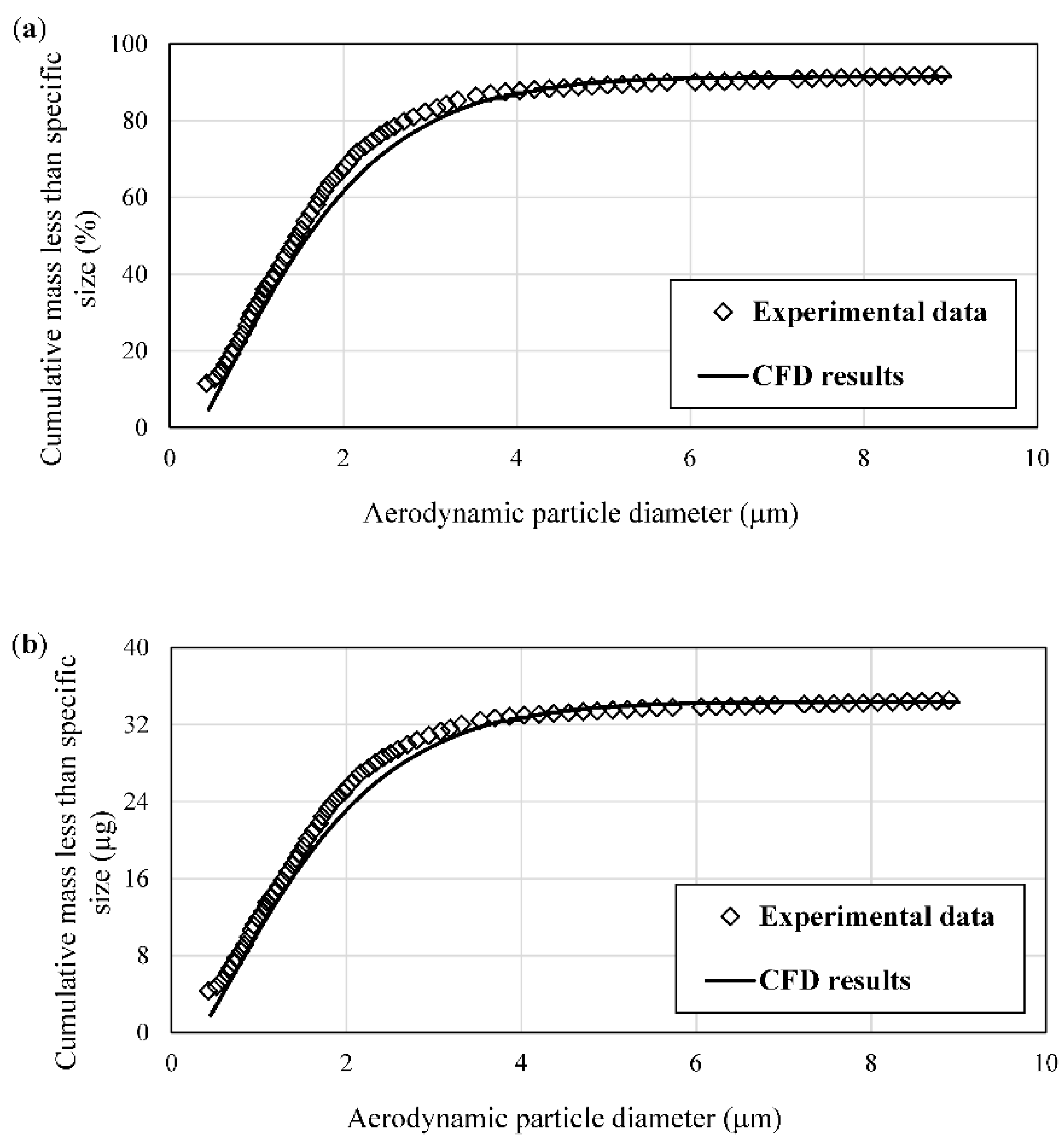
3.1. CFD Model Validation

We validated our CFD model with the experiments conducted by Lewis et al. [31] on drug deposition in the mouth–throat airway. The validation was performed for a flow rate of 28.3 L/min. The curves of cumulative mass in terms of percentage and mass units per aerodynamic particle diameter were compared at the outlet surface and plotted in Figure 3. Pharmaceutical companies typically use the aerodynamic diameter to characterize particles in inhalable drugs. The aerodynamic diameter is defined as the diameter of the spherical particle with standard density ( ρ 0 ) (1000 kg/m3) and the same settling velocity as the irregular particle with a diameter d p and density ρ p . It can be calculated using the Equation (13):
d a = d p ( ρ p ρ 0 ) 1 / 2
where d a is the aerodynamic diameter of an irregular particle [50].
The cumulative mass % RMSEs were 0.0899 (based on Figure 3a) and 0.0789 (Figure 3b); the total mass observed in the reference experiment (34.5 µg) and that obtained from this CFD study (34.32 µg) varied by a relative error of about 0.5%. This showed that our CFD results agreed well with the experimental results. The deviation between the experimental work and our simulation results may be explained in a couple of ways. In our CFD simulation, the airway surface was treated as smooth, whereas in the experiments, there would exist some form of microroughness on the surface. This would affect the near-wall fluid and particle interaction. The other reason is that the Reynolds-averaged Navier–Stokes (RANS) turbulence models can never be perfect, especially in complicated geometries containing recirculation, pressure drop, and flow separation, but these adopted turbulence models, especially the k-ω model, generally perform well in the literature [1,22,49].

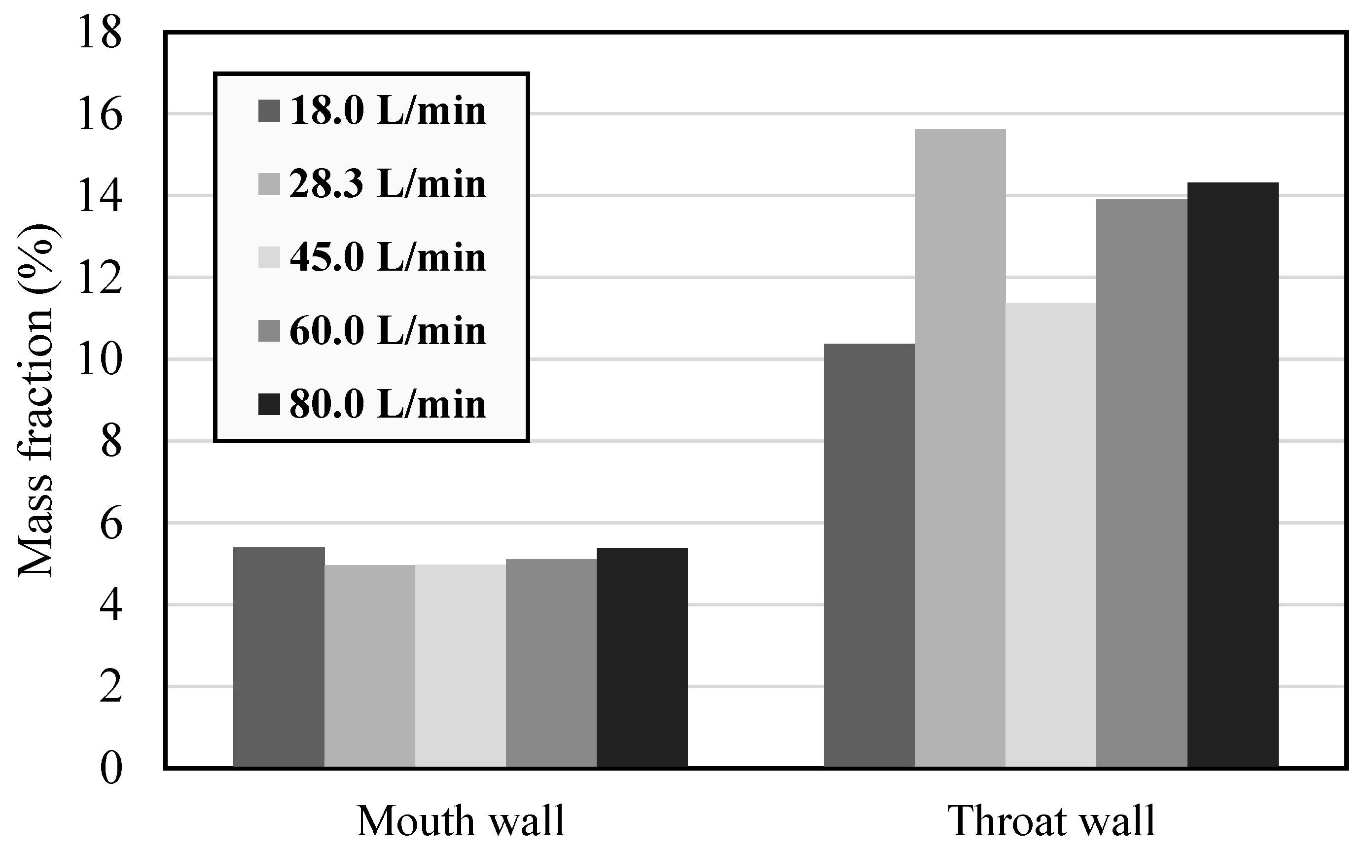
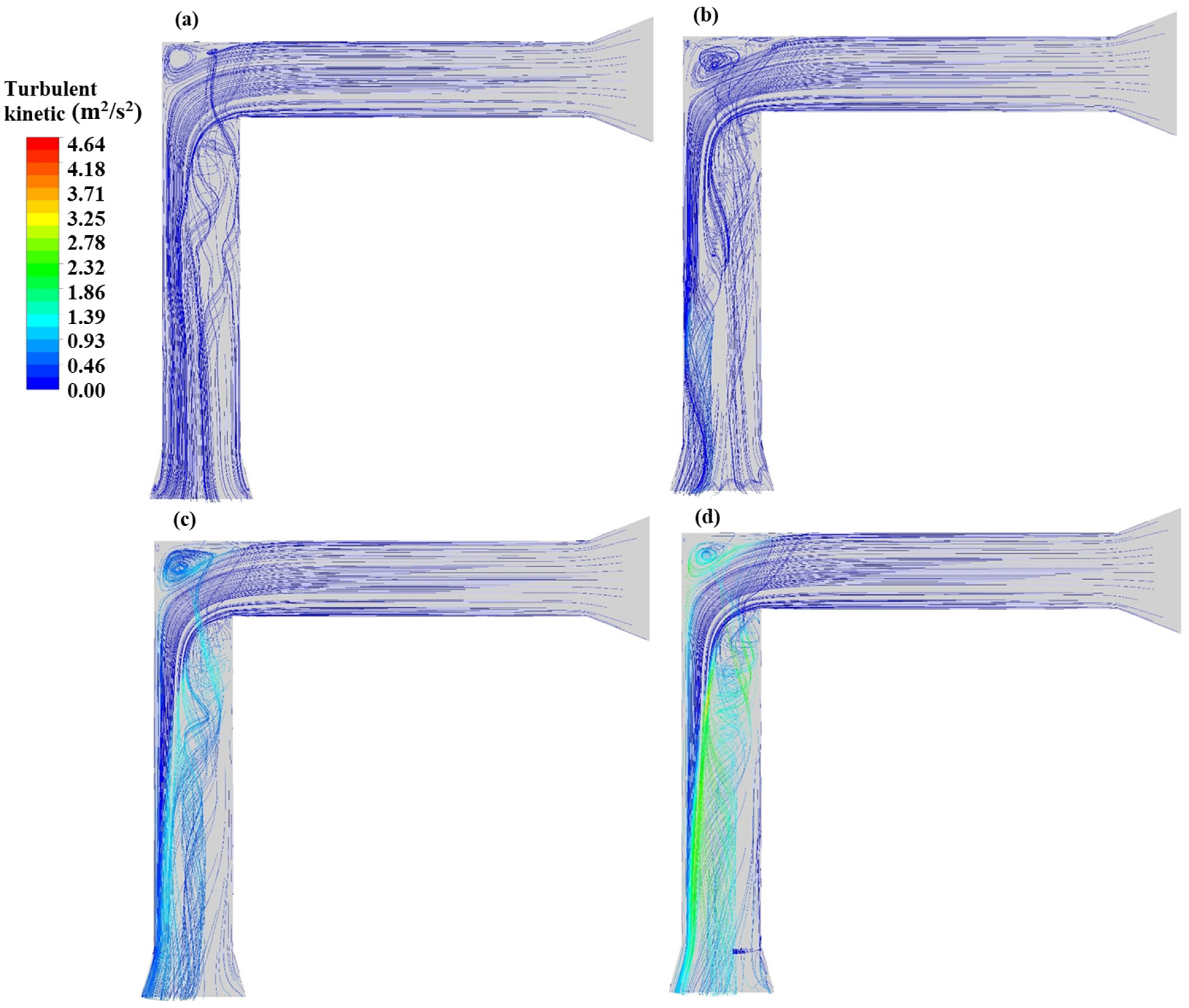
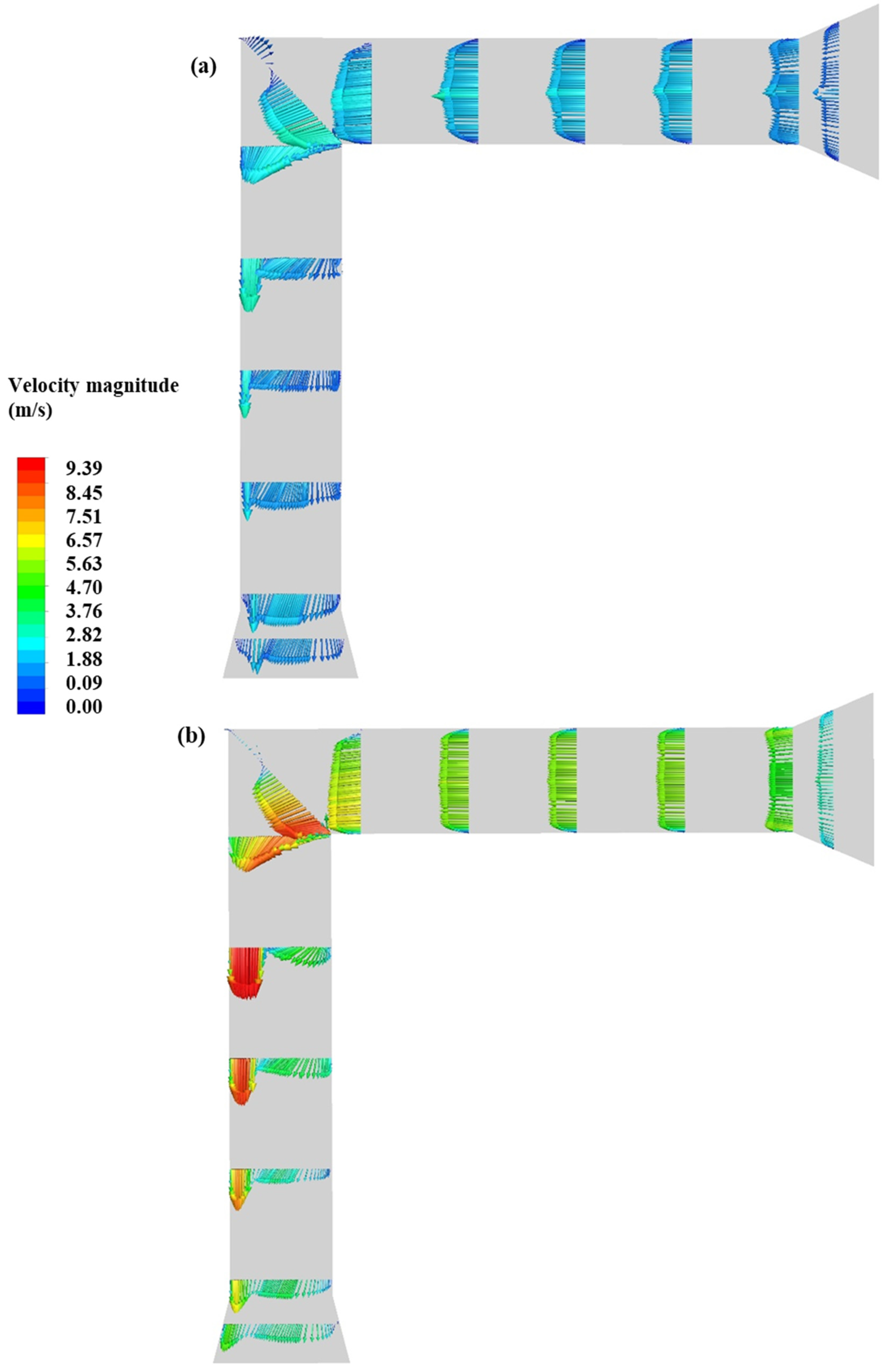
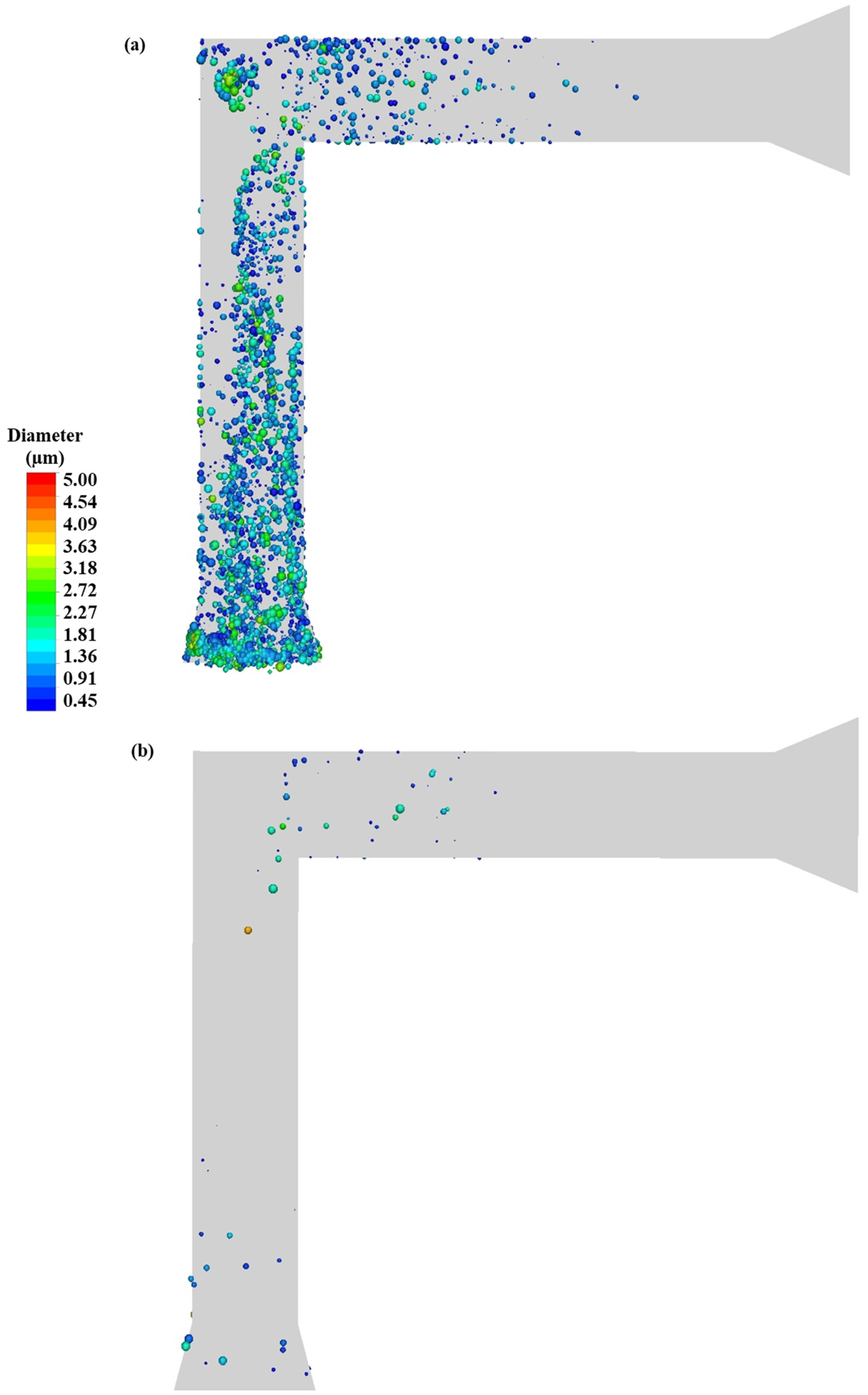
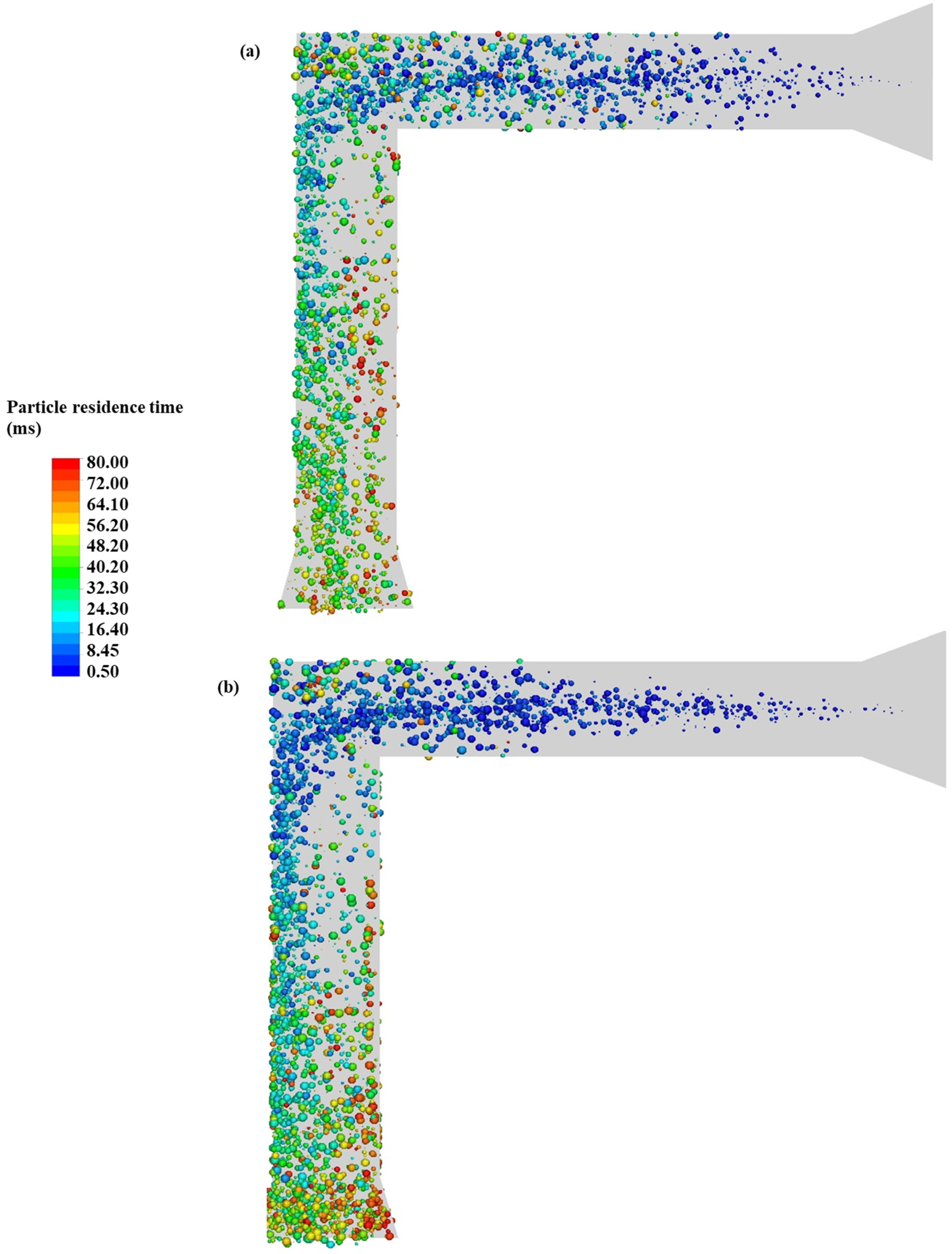
3.2. Impact of Flow Rate

Table 4 shows the effect of five different flow rates on particle deposition and particle diameter. Our data showed that particle deposition decreased when the flow rate increased from 18.0 to 60.0 L/min and then slightly decreased at 80.0 L/min. The experimental data for particle deposition for 28.3 reported the same pattern of deposition decrease with a flow rate increase. However, due to ACI limitations for flow rates higher than 28.3 L/min, Lewis et al. [31] actuated multiple times to achieve a robust detection for each ACI stage. Therefore, the amount of particle dose that entered their experimental mouth–throat airway was different from our model for flow rates higher than 28.3 L/min. However, our goal was to study the impact of flow rate, which required a constant drug dose during one actuation.
The mass median aerodynamic diameter (MMAD) is defined when 50% of the particles of an aerosol by mass are larger than the rest at a specific diameter. Thus, the MMAD divides the aerosol size distribution in half. The MMAD of an inhaled aerosol is important since it is directly related to particle size distribution. The inhaled aerosol particle size distribution must have the proper fraction of fine particles delivered to the lungs in order to be effective for the patient’s health [50]. As seen in Table 4, the MMAD decreased as the flow rate increased up to 60.0 L/min. The increase in flow rate caused more particles to break inside the mouth–throat airway, thereby creating smaller diameter particles, and resulting in a narrower particle size distribution. However, any further increase in the flow rate to 80.0 L/min did not show any significant effect on the MMAD as reported by Lewis et al. [31].
Figure 4 shows the cumulative mass versus drug aerodynamic diameter for five flow rates. This figure shows that as the flow rate increased the mass of fine drug particles reaching the outlet slightly increased. We also noticed that as the flow rate increased the particle size distribution shifted to the finer sizes. Li et al. [51] observed more fine particles at higher flow rates due to both a high particle velocity and turbulent kinetic energy in the mouth–throat airway. The same pattern was observed in the Lewis et al. [31] study when the flow rate increased up to 84.9 L/min. This is important since generally, particles in the size range of 1 to 5 µm have the highest chance to reach deep inside the lung [52]. Feddah et al. [53] conducted an in vitro experiment to compare the performance of DPI and MDI inhalers through the induction port. Their results showed that increasing the flow rate from 30.0 to 60.0 L/min led to a finer particle size distribution [53]. Moreover, there was no significant difference when the flow rate increased up to 90.0 L/min. Yousefi et al. [29] designed a model for an oral-pharynx cavity that was a replica of the experimental work of Cheng et al. [54]. They reported that the flow rates did not affect the lung deposition efficiency in their study.
Figure 5 shows the simulated particle deposition on mouth and throat surfaces (walls) in terms of mass as a histogram. We can see almost no significant changes occurred in particle deposition at the mouth as the flow rate increased. However, the deposition fraction in the throat decreased as the flow rate increased. Longest et al. [55] performed a CFD study on particle deposition of MDI through two different mouth–throat airway geometries. They reported the particle deposition on the throat wall was slightly lower than on the mouth wall at 30.0 L/min [55]. The impact of flow rate on the mouth and throat particle deposition can be explained more accurately by analyzing the hydrodynamics of the particles and airflow through the mouth–throat airway at different flow rates.
Figure 6 shows the impact of flow rates on the turbulent kinetic energy through the mouth–throat airway at 0.08 s. The recirculation flows at the 90° bend are noticeable in all plots. However, this figure shows that increasing airflow rate can also cause a more powerful recirculation flow at the 90° bend, which can entrap more fine particles in this zone. This figure also shows that an enhancement in the flow rate creates higher fluctuation energy mostly in the throat zone. Since turbulent kinetic energy is attributed to velocity fluctuation, its higher values confirmed that particles that lost their initial momentum at the end of the injection (i.e., at 0.1 s) travelled by the airflow to pass the throat and therefore the throat’s particle deposition decreased as flow rates increased (refer to Figure 5). Tang et al. [56] investigated the impact of different induction ports on the deagglomeration of particles with a constant flow rate of 100 L/min. They noticed a high intensity in the turbulent kinetic energy below the 90° bend [56].
Air velocity profiles at different flow rates in the mouth–throat airway geometries at 0.08 s are displayed using velocity vector plots in Figure 7. At the flow rate of 28.3 L/min (Figure 7a), the velocity profiles had a higher value in the centerline with a small circulation streamline at the corner of the 90° bend. As flow rates increased to 80.0 L/min (Figure 7b), the velocity profiles became more uniform in the mouth zone with higher velocity profiles at the back of the throat. This flow pattern has also been observed by Longest et al. [55]. They observed the intense air velocity profiles skewed toward the outer wall of the throat geometry with a flow rate of 30.00 L/min. This behaviour was justified because of the significant recirculation zone at the 90° bend [55].
Figure 8 shows the air streamlining at the 80.0 L/min flow rate at the 90° bend. We can see two main flow streams at the 90° bend. Part of the airflow recirculated and part of it passed through the 90° bend and entered the throat area. The recirculation flow resends the particles to the mouth zone, which is not desirable. Gjellerup et al. [57] investigated the flow hydrodynamic inside two different airway geometries via in vitro and CFD studies. They observed the recirculation area at the 90° bend at 30.0 L/min as well [57]. They observed that the recirculation flow can push fluid against the main flow stream direction toward the inlet in a very thin region close to the mouth wall [57].
Figure 9 displays the fine particle (less than 5 µm) diameters for different flow rates at 0.2 s (e.g., post actuation). As can be seen in Figure 9a, since the 28.3 L/min flow rate was not sufficient to keep the fine particles together in the centerline, most of the fine particles can be seen in the mouth–throat airway due to the low flow rate and greater deposition on the mouth–throat wall. In fact, after particles reached their stopping distance, they needed the continuous phase (i.e., air) to travel through the mouth–throat airway to the outlet. As the flow rate increased up to 80.0 L/min (Figure 9b), a small number of fine particles were still in the mouth–throat airway; most of the particles were either deposited or passed the mouth–throat airway at the time frame of 0.2 s. We expected to not see fine particles in the mouth area at 0.2 s; however, due to the intense recirculation flow at the 90° bend as previously shown in Figure 8, some submicron particles appeared to have been pushed back to the mouth zone. Yousefi et al. [29] concluded that smaller particles showed more scattered deposition patterns due to a lack of enough drag force at lower flow rates. Therefore, fine particles at a 15.0 L/min flow rate, in comparison to 30 L/min, may separate from the main air stream and deposit on the airway wall slowly over time. Whereas at higher flow rates, such as 60.0 L/min, the particles’ inertial force increases, causing deposition on the mouth–throat wall in a shorter period.

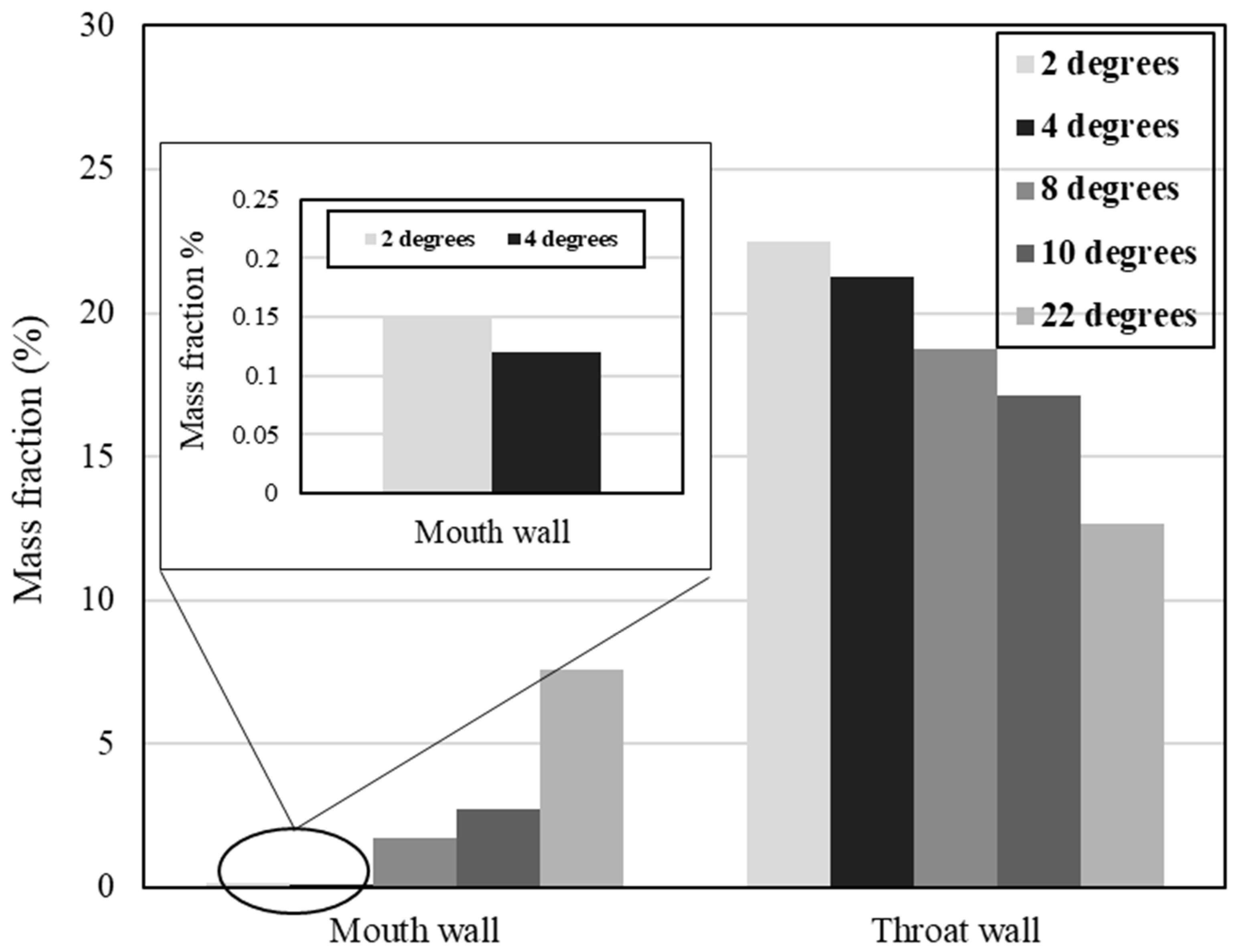
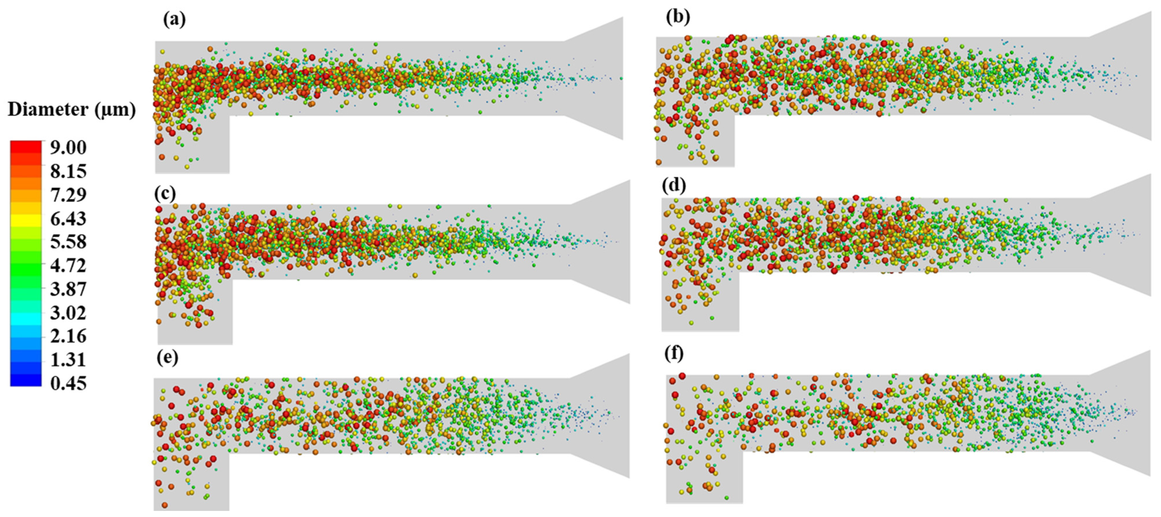
3.3. Impact of Cone Angle

Figure 10 shows the impact of spray cone angles ranging from 2° to 22° at the constant flow rate of 28.3 L/min on drug particle deposition. The particle mass fraction deposited on the mouth wall at a cone angle of 2° was the lowest with 0.14% deposition; however, for the same cone angle, the deposition on the throat wall was the highest. Our results show that the particle mass fraction had a gradual increase from 0.14% to 7.56% and 77.35% to 79.79% as the spray cone angle increased from 2° to 22° in the case of the mouth wall and throat wall, respectively. Ahookhosh et al. [7] also modeled a real-life upper respiratory tract geometry and reported 29% of mass fraction deposition with a spray cone angle of 20°. We found 20.2% of mass fraction deposition for a 22° spray cone angle. This difference can be due to the fact that they considered a higher spray velocity (60.0 L/min) in comparison to our study (28.3 L/min) and the 2° difference between the two cone angles studied (i.e., 20° and 22°). Figure 10 also shows that at both minimum and maximum cone angles, 2° and 22°, respectively, the particle mass fraction exiting the mouth–throat airway’s outlet was approximately the same. Therefore, the cone angle particularly affects particle depositions on the mouth and throat walls. Our results showed that the 8° spray cone angle was the best choice among the investigated spray cone angles since it controlled particle depositions on both the mouth and throat walls.
Figure 11 shows the particle diameter tracking for the aerosol plume after 0.01 s of actuation at the constant flow rate of 28.3 L/min as the cone angles varied from 2° to 22°. Smaller cone angles produced larger diameter particles (i.e., >5 µm) mostly on the centerline in the mouth area and specifically at the 90° bend, which is not appropriate for patients. At the larger cone angles, wider aerosol plumes were formed near the nozzle, thus covering a larger space in the mouth area. At the highest cone angles (as shown in Figure 11e,f) the aerosol plume almost covered the entire mouth zone space from the beginning of actuation; consequently, the highest mouth deposition occurred with these cone angles. For medium-sized cone angles, i.e., 8° and 17°—especially 8°—an aerosol plume was created with smaller particle diameters and covered the mouth zone at an acceptable distance from the nozzle. Yousefi et al. [29] investigated the effect of the spray cone angle (0°–10°) on the wall deposition. They observed that increasing the spray cone angle in their investigative range helped more particles to be delivered to the lungs [29]. They also confirmed that very high spray cone angles caused a lower efficiency [29].
Figure 12 shows the particle residence time at 0.08 s after actuation for two different flow rates. At the flow rate of 60.0 L/min, particles in the throat area, especially the lower part of the mouth–throat airway, had a shorter residence time compared to that of the 28.3 L/min flow rate. At the lower flow rate, more fine particles were trapped at the 90° bend due to Brownian motion. Some particles were still in the mouth area (higher residence time). Meanwhile, by increasing the flow rate to 60.0 L/min, more particles either passed the bend and reached the lower part of the throat area (i.e., left the mouth–throat airway) or deposited in the airways. Oliveira et al. [1] discussed their CFD study of particle residence time through the actuation in the open air. Their results showed a similar pattern with finer particles located near the nozzle [1]. Moreover, particles with a high particle residence time still existed near the orifice and were expected to move forward as time passed.

4. Conclusions

We used a CFD study to address the effect of flow rates and cone angles on the spray plume and drug particle deposition in a simulated mouth–throat airway. Our CFD model was first validated with experimental results [31]. As the flow rate increased, larger particles with aerodynamic particle diameters of 5–9 µm deagglomerated, and finer particles were produced. As the flow rate increased, mouth particle deposition remained almost constant while throat particle deposition decreased gradually since the lower airflow rates did not create sufficient drag force to deliver the particles through the mouth–throat airway. Once particles lost their initial momentum, they were more dependent on the airflow to pass the throat after actuation. Increasing the cone angle from 2° to 22° at a constant flow rate mainly impacted mouth particle deposition. Particle deposition showed a greater dependency on the cone angle rather than the flow rate. As the cone angle changed to 8° or 10°, throat deposition decreased, and the spray plume showed a proper particle size distribution. At the smaller cone angles, larger particles were produced, especially at the centerline and more fine particles were trapped at the 90° bend due to Brownian motion. However, higher (greater than 8°) cone angles directed particles to the inhaler nozzle and mouth cavity boundaries, thus increasing mouth particle deposition and reducing the efficiency of the pMDI in the mouth–throat drug delivery. Moreover, at a higher flow rate, at 8°, large particles tended to move in the centerline yielding less mouth deposition.

Author Contributions

Conceptualization, F.D. and L.P.; methodology, F.D. and L.P.; software, F.D.; validation, F.D.; formal analysis, F.D. and L.P.; investigation, F.D. and L.P.; resources, L.P. and J.K.; data curation, F.D.; writing—original draft preparation, F.D. and L.P.; writing—review and editing, L.P.; visualization, F.D.; supervision, L.P., J.K. and E.B.; project administration, L.P.; funding acquisition, L.P. and J.K. All authors have read and agreed to the published version of the manuscript.

Funding

This research received funding from the Natural Sciences and Engineering Council of Canada (NSERC).

Institutional Review Board Statement

Not applicable.

Informed Consent Statement

Not applicable.

Data Availability Statement

Not applicable.

Acknowledgments

We gratefully acknowledge the financial support of the Natural Sciences and Engineering Council of Canada (NSERC). We would also like to acknowledge the support of Lakehead University’s High-Performance Computing Center for providing the solving platform and technical support.

Conflicts of Interest

The authors declare no conflict of interest.

Nomenclature

Abbreviations
COPDchronic obstructive pulmonary disease
pMDIpressurized metered-dose inhaler
CFDcomputational fluid dynamics
APSDaerodynamic particle size distribution
IPinduction port
USPUnited States pharmacopeia
TKEturbulent kinetic energy
3D3- dimensional
BDPbeclomethasone dipropionate particles
RMSEroot-mean-square error
SIMPLEsemi-implicit method for pressure-linked equations
MMADmass median aerodynamic diameter
Notations
d p particle diameter, (µm)
d ¯ mean diameter, (µm)
k turbulent kinetic energy, (m2/s2)
C D constant drag coefficient, (-)
V p particle velocity, (m/s)
ReReynolds number, (-)
q spread parameter, (-)
Q fraction of total mass, (-)
Xdynamic shape factor, (-)
K coefficient of proportionality, (-)
d a aerodynamic diameter, (µm)
u ¯ i time-averaged velocity, (m/s)
p static pressure, (Pa)
Greek letters
ρ 0 standard density, (kg/m3)
ρ fluid specific mass, (kg)
ρ p particle density, (kg/m3)
ν kinematic viscosity, (m2/s)
ν T turbulent viscosity, (m2/s)
η viscosity of gas, (m2/s)
ρ g gas density, (kg/m3)
ω turbulent dissipation rate, (s−1)
β * , σ k , α , β, σ ω constant coefficient of SST model, (-)
m ˙ mass flow rate, (kg/s)

References

  1. Oliveira, R.F.; Teixeira, S.F.; Silva, L.F.; Teixeira, J.C.; Antunes, H. Development of new spacer device geometry: A CFD study (part I). Comput. Methods. Biomech. Biomed. Eng. 2012, 15, 825–833. [Google Scholar] [CrossRef] [PubMed]
  2. McDonald, K.J.; Martin, G.P. Transition to CFC-free metered dose inhalers into the new millennium. Int. J. Pharm. 2000, 201, 89–107. [Google Scholar] [CrossRef]
  3. Rau, J.L. The inhalation of drugs: Advantages and problems. Respir. Care 2005, 50, 367–382. [Google Scholar] [PubMed]
  4. Cochrane, M.G.; Bala, M.V.; Downs, K.E.; Mauskop, J.; Ben-Joseph, R.H. Inhaled corticosteroids for asthma therapy: Patient compliance, devices, and inhalation technique. Chest 2000, 117, 542–550. [Google Scholar] [CrossRef] [PubMed]
  5. Kofman, C.; Berlinski, A.; Zaragoza, S.; Teper, A. Aerosol therapy for pediatric outpatients. J. Respir. Care. Pract. 2004, 117, 26–28. [Google Scholar]
  6. Dutta, R.; Spence, B.; Wei, X.; Dhapare, S.; Hindle, M.; Longest, P.W. CFD guided optimization of nose-to-lung aerosol delivery in adults: Effects of inhalation waveforms and synchronized aerosol delivery. Pharm. Res. 2020, 37, 199. [Google Scholar] [CrossRef]
  7. Ahookhosh, K.; Saidi, M.; Mohammadpourfard, M.; Aminfar, H.; Hamishehkar, H.; Farnoud, A.; Schmid, O. Flow structure and particle deposition analyses for optimization of a pressurized metered dose inhaler (pMDI) in a model of tracheobronchial airway. Eur. J. Pharm. Sci. 2021, 164, 105911. [Google Scholar] [CrossRef]
  8. Clarke, A.R. Medical aerosol inhalers: Past, present, and future. Aerosol Sci. Technol. 1995, 22, 374–391. [Google Scholar] [CrossRef] [Green Version]
  9. Longest, P.W.; Hindle, M. CFD simulations of enhanced condensational growth (ECG) applied to respiratory drug delivery with comparisons to in vitro data. J. Aerosol Sci. 2010, 41, 805–820. [Google Scholar] [CrossRef] [Green Version]
  10. Martin, A.R.; Finlay, W.H. The effect of humidity on the size of particles delivered from metered-dose inhalers. Aerosol Sci. Technol. 2005, 39, 283–289. [Google Scholar] [CrossRef]
  11. Mitchell, J.P.; Nagel, M.W.; Wiersema, K.J.; Doyle, C.C.; Migounov, V.A. The effect of humidification on the size distribution of aerosols delivered to the mechanically ventilated patient. In Proceedings of the 14th International Society for Aerosols in Medicine Congress, Baltimore, MD, USA, 14–18 June 2003. [Google Scholar]
  12. Hindle, M.; Longest, P.W. Evaluation of enhanced condensational growth (ECG) for controlled respiratory drug delivery in a mouth-throat and upper tracheobronchial model. Pharm. Res. 2010, 27, 1800–1811. [Google Scholar] [CrossRef] [PubMed] [Green Version]
  13. Zhang, Y.; Finlay, W.H.; Matida, E.A. Particle deposition measurements and numerical simulation in a highly idealized mouth–throat. J. Aerosol Sci. 2004, 35, 789–803. [Google Scholar] [CrossRef]
  14. Dhand, R. Inhalation therapy with metered-dose inhalers and dry powder inhalers in mechanically ventilated patients. Respir. Care. 2005, 50, 1331–1345. [Google Scholar] [PubMed]
  15. Zhu, B.; Traini, D.; Young, P. Aerosol particle generation from solution-based pressurized metered dose inhalers: A technical overview of parameters that influence respiratory deposition. Pharm. Dev. Technol. 2015, 20, 897–910. [Google Scholar] [CrossRef] [PubMed]
  16. Berry, J.; Heimbecher, S.; Hart, J.L.; Sequeira, J. Influence of the metering chamber volume and actuator design on the aerodynamic particle size of a metered dose inhaler. Drug Dev. Ind. Pharm. 2003, 29, 865–876. [Google Scholar] [CrossRef] [PubMed]
  17. Ruzycki, C.A.; Javaheri, E.; Finlay, W.H. The use of computational fluid dynamics in inhaler design. Expert Opin. Drug Deliv. 2013, 10, 307–323. [Google Scholar] [CrossRef]
  18. Vinchurkar, S.; Longest, P.W.; Peart, J. CFD simulations of the Andersen cascade impactor: Model development and effects of aerosol charge. J. Aerosol Sci. 2009, 40, 807–822. [Google Scholar] [CrossRef]
  19. Oliveira, R.F.; Ferreira, A.C.; Teixeira, S.F.; Teixeira, J.C.; Marques, H.C. pMDI spray plume analysis: A CFD study. In Proceedings of the World Congress on Engineering, London, UK, 3–5 July 2013. [Google Scholar]
  20. Buchmann, N.A.; Duke, D.J.; Shakiba, S.A.; Mitchell, D.M.; Stewart, P.J.; Traini, D.; Honnery, D.A. Novel high-speed imaging technique to predict the macroscopic spray characteristics of solution based pressurized metered dose inhalers. Pharm. Res. 2014, 31, 2963–2974. [Google Scholar] [CrossRef]
  21. Cheng, Y.S.; Zhou, Y.; Su, W.C. Deposition of particles in human mouth–throat replicas and a USP induction port. J. Aerosol Med. Pulm. Drug Deliv. 2015, 28, 147–155. [Google Scholar] [CrossRef]
  22. Bass, K.; Longest, P.W. Recommendations for simulating microparticle deposition at conditions similar to the upper airways with two-equation turbulence models. J. Aerosol Sci. 2018, 119, 31–50. [Google Scholar] [CrossRef]
  23. Koullapis, P.; Kassinos, S.C.; Muela, J.; Perez-Segarra, C.; Rigola, J.; Lehmkuhl, O.; Nicolaou, L. Regional aerosol deposition in the human airways: The SimInhale benchmark case and a critical assessment of in silico methods. Eur. J. Pharm. Sci. 2018, 113, 77–94. [Google Scholar] [CrossRef] [PubMed] [Green Version]
  24. Duke, D.J.; Scott, H.N.; Kusangaya, A.J.; Kastengren, A.L.; Matusik, K.; Young, P.; Honnery, D. Drug distribution transients in solution and suspension-based pressurized metered dose inhaler sprays. Int. J. Pharm. 2019, 566, 463–475. [Google Scholar] [CrossRef] [PubMed]
  25. Ganderton, D.; Lewis, D.; Davies, R. The formulation and evaluation of a CFC-free budesonide pressurized metered dose inhaler. Respir. Med. 2003, 97, S4–S9. [Google Scholar] [CrossRef] [PubMed] [Green Version]
  26. Smyth, H.; Brace, G.; Barbour, T.; Gallion, J.; Grove, J.; Hickey, A.J. Spray pattern analysis for metered dose inhalers: Effect of actuator design. Pharm. Res. 2006, 23, 1591–1596. [Google Scholar] [CrossRef] [PubMed]
  27. Fadl, A.; Wang, J.; Zhang, Z.; Cheng, Y.S. Effects of MDI spray angle on aerosol penetration efficiency through an oral airway cast. J. Aerosol Sci. 2007, 38, 853–864. [Google Scholar] [CrossRef]
  28. Gavtash, B.; Versteeg, H.; Hargrave, G.; Myatt, B.; Lewis, D.; Church, T.; Brambilla, G. Multi-physics theoretical approach to predict pMDI spray characteristics. Drug Deliv. Lungs. 2017, 27, 73–76. [Google Scholar]
  29. Yousefi, M.; Inthavong, K.; Tu, J. Effect of pressurized metered dose inhaler spray characteristics and particle size distribution on drug delivery efficiency. J. Aerosol Med. Pulm. Drug Deliv. 2017, 30, 359–372. [Google Scholar] [CrossRef]
  30. Chen, Y.; Young, P.M.; Murphy, S.; Fletcher, D.F.; Long, E.; Lewis, D.; Traini, D. High-speed laser image analysis of plume angles for pressurised metered dose inhalers: The effect of nozzle geometry. AAPS PharmSciTech 2017, 18, 782–789. [Google Scholar] [CrossRef] [Green Version]
  31. Lewis, D.A.; O’Shea, H.; Church, T.K.; Brambilla, G.; Traini, D.; Young, P.M. Exploring the impact of sample flowrate on in vitro measurements of metered dose inhaler performance. Int. J. Pharm. 2016, 514, 420–427. [Google Scholar] [CrossRef] [Green Version]
  32. ANSYS® Inc. ANSYS Fluent Theory Guide; Release. R1, v193; ANSYS® Inc.: Canonsburg, PA, USA, 2019. [Google Scholar]
  33. Newman, S.P. Principles of metered-dose inhaler design. Respir. Care 2005, 50, 1177–1190. [Google Scholar]
  34. Mortazavi, H.; Pakzad, L. The hydrodynamics and mixing performance in a moving baffle oscillatory baffled reactor through computational fluid dynamics (CFD). Processes 2020, 8, 1236. [Google Scholar] [CrossRef]
  35. Moskal, A.; Gradoń, L. Temporary and spatial deposition of aerosol particles in the upper human airways during breathing cycle. J. Aerosol Sci. 2002, 33, 1525–1539. [Google Scholar] [CrossRef]
  36. Longest, P.W.; Holbrook, L.T. In silico models of aerosol delivery to the respiratory tract—Development and applications. Adv. Drug Deliv. Rev. 2012, 64, 296–311. [Google Scholar] [CrossRef] [PubMed] [Green Version]
  37. Crowe, C.T.; Troutt, T.R.; Chung, J. Numerical models for two-phase turbulent flows. Annu. Rev. Fluid Mech. 1996, 28, 11–43. [Google Scholar] [CrossRef]
  38. Anderson, T.B.; Jackson, R. Fluid mechanical description of fluidized beds. Equations of motion. Ind. Eng. Chem. Fundam. 1967, 6, 527–539. [Google Scholar] [CrossRef]
  39. Wilcox, D.C. Turbulence Modeling for CFD; DCW industries: Palm Drive La Canada Flintridge, CA, USA, 1998; Volume 2, pp. 103–217. [Google Scholar]
  40. Versteeg, H.K.; Malalasekera, W. An Introduction to Computational Fluid Dynamics: The Finite Volume Method; Pearson education: London, UK, 2007. [Google Scholar]
  41. Paul, M.M.; Pakzad, L. Bubble size distribution and gas holdup in bubble columns employing non-Newtonian liquids: A CFD Study. Can. J. Chem. Eng. 2022, 1–17. [Google Scholar] [CrossRef]
  42. Li, Z.; Kleinstreuer, C.; Zhang, Z. Simulation of airflow fields an microparticle deposition in realistic human lung airway models. part i: Air flow patterns. Eur. J. Mech. B/Fluids 2007, 26, 632–649. [Google Scholar] [CrossRef]
  43. Clift, R.; Grace, J.R.; Weber, M.E. Bubbles, Drops, and Particles; Academic Press Inc.: New York, NY, USA, 1978. [Google Scholar]
  44. Buckley, R.; Loyalka, S. Cunningham correction factor and accommodation coefficient: Interpretation of Millikan’s data. J. Aerosol Sci. 1989, 20, 347–349. [Google Scholar] [CrossRef]
  45. Cunningham, E. On the velocity of steady fall of spherical particles through fluid medium. Proceedings of the Royal Society of London. Math. Phys. 1910, 83, 357–365. [Google Scholar]
  46. Inthavong, K.; Ye, Y.; Ding, S.; Tu, J. Comparative study of the effects of acute asthma in relation to a recovered airway tree on airflow patterns. In Proceedings of the 13th International Conference on Biomedical Engineering, Singapore, 3–6 December 2008; pp. 1555–1558. [Google Scholar]
  47. Alatrash, A.; Matida, E. Characterization of medication velocity and size distribution from pressurized metered-dose inhalers by phase Doppler anemometry. J. Aerosol Med. Pulm. Drug Deliv. 2016, 29, 501–513. [Google Scholar] [CrossRef]
  48. Dunham, R.Q. Rosin-Rammler Distributions in ANSYS Fluent (No. LA-UR-12-24026); Los Alamos National Lab (LANL): Los Alamos, NM, USA, 2012. [Google Scholar]
  49. Sarkar, S.; Peri, S.P.; Chaudhuri, B. Investigation of multiphase multicomponent aerosol flow dictating pMDI-spacer interactions. Int. J. Pharm. 2017, 529, 264–274. [Google Scholar] [CrossRef]
  50. Finlay, W.H.; Darquenne, C. Particle size distributions. J. Aerosol Med. Pulm. Drug Deliv. 2020, 33, 178–180. [Google Scholar] [CrossRef]
  51. Li, W.I.; Perzl, M.; Heyder, J.; Langer, R.; Brain, J.D.; Englmeier, K.H.; Edwards, D.A. Aerodynamics and aerosol particle deaggregation phenomena in model oral-pharyngeal cavities. J. Aerosol Sci. 1996, 27, 1269–1286. [Google Scholar] [CrossRef]
  52. Nave, R.; Mueller, H. From inhaler to lung: Clinical implications of the formulations of ciclesonide and other inhaled corticosteroids. Int. J. Gen. Med. 2013, 6, 99. [Google Scholar]
  53. Feddah, M.R.; Brown, K.F.; Gipps, E.M.; Davies, N.M. In-vitro characterization of metered dose inhaler versus dry powder inhaler glucocorticoid products: Influence of inspiratory flow rates. J. Pharm. Pharm. Sci. 2007, 3, 318–324. [Google Scholar]
  54. Cheng, Y.S.; Zhou, Y.; Chen, B.T. Particle deposition in a cast of human oral airways. Aerosol Sci. Technol. 1999, 31, 286–300. [Google Scholar] [CrossRef]
  55. Longest, P.W.; Hindle, M.; Choudhuri, S.D.; Xi, J. Comparison of ambient and spray aerosol deposition in a standard induction port and more realistic mouth–throat geometry. J. Aerosol Sci. 2008, 39, 572–591. [Google Scholar] [CrossRef]
  56. Tang, P.; Kwok, P.C.L.; Tong, Z.; Yang, R.; Raper, J.A.; Chan, H.K. Does the United States Pharmacopeia throat introduce de-agglomeration of carrier-free powder from inhalers? Pharm. Res. 2012, 29, 1797–1807. [Google Scholar] [CrossRef]
  57. Gjellerup, C.; Frederiksen, S.O. CFD and PIV investigation of the flow inside the USP throat and in a replica of the human upper airways. Joint Dissertation (MSc), Technical University of Denmark, Lyngby, Denmark, 2007. [Google Scholar]
Figure 1. Schematic of mouth–throat airway with mesh’s (a) side view and (b) cross-sectional area.
Processes 10 01230 g001
Figure 2. Mesh independency study on the tangential air velocity (u) at: (a) 0.08 s and (b) 0.12 s.
Processes 10 01230 g002
Figure 3. Model validation using cumulative mass based on: (a) percentage and (b) microgram per aerodynamic particle diameter.
Processes 10 01230 g003
Figure 4. Cumulative mass percentage per aerodynamic particle diameter at different flow rates.
Processes 10 01230 g004
Figure 5. Particle deposition on the various solid surfaces with a spray cone angle of 17° at different flow rates.
Processes 10 01230 g005
Figure 6. Turbulent kinetic energy path’s line plots at 0.08 s for different flow rates: (a) 18.0 L/min, (b) 28.3 L/min, (c) 60.0 L/min, and (d) 80.0 L/min.
Processes 10 01230 g006
Figure 7. Air velocity vector plots at 0.08 s for different flow rates: (a) 28.3 L/min, (b) 80.0 L/min.
Processes 10 01230 g007
Figure 8. Air streamlines inside the mouth–throat airway geometry at 0.08 s for the flow rate of 80.0 L/min.
Processes 10 01230 g008
Figure 9. Particle diameter tracking at 0.2 s for different flow rates: (a) 28.3 L/min and (b) 80.0 L/min (spheres with proportional size scaled 200 times more than the real diameter).
Processes 10 01230 g009
Figure 10. Particle deposition on the various solid surfaces at the flow rate of 28.3 L/min with different cone angles.
Processes 10 01230 g010
Figure 11. Particle tracking based on diameter (µm) at 0.01 s at the flow rate of 28.3 L/min for different cone angles: (a) 2°, (b) 4°, (c) 8°, (d) 10°, (e) 17°, and (f) 22° (spheres with proportional size scaled 200 times more than the real diameter).
Processes 10 01230 g011
Figure 12. Particle residence time (s) for a spray cone angle of 8° at the flow rates of: (a) 28.3 L/min, and (b) 60.0 L/min (spheres with proportional size scaled 200 times more than the real diameter).
Processes 10 01230 g012
Table 1. Values of spray cone angle and flow rate.
Flow Rate (L/min)
18.028.345.060.080.0
Spray Cone Angle (°)
248101720
Table 2. Cell size and the number of cells.
ParameterCell Size (mm)Number of Cells
Mesh A2.00114,825
Mesh B1.98222,150
Mesh C1.68414,589
Mesh D 0.82812,448
Table 3. Spray and particle distribution parameters.
Distribution modelRosin–Rammler
Minimum diameter (µm)0.45
Maximum diameter (µm)9
Mean diameter (µm)1.828
Spread parameter (-)1.3676
Initial velocity (m/s)100
Spray cone angle (°)17
Table 4. Particle deposition efficiency and MMAD at different flow rates.
Flow rates (L/min)18.028.345.060.080.0
Particle deposition in IP (%)12.49.58.17.57.1
MMAD (µm)1.8 ± 0.11.6 ± 0.11.5 ± 0.11.4 ± 0.11.4 ± 0.1
Publisher’s Note: MDPI stays neutral with regard to jurisdictional claims in published maps and institutional affiliations.

