Article

Indirect Contact Chamber with Dielectric Layers for Pulsed Electric Field Treatment of Microorganisms

1
School of Electrical Engineering, Guangxi University, Nanning 530004, China
2
College of Life Science and Technology, Guangxi University, Nanning 530004, China
*
Author to whom correspondence should be addressed.
Processes 2022, 10(11), 2432; https://doi.org/10.3390/pr10112432
Submission received: 19 August 2022 / Revised: 10 November 2022 / Accepted: 12 November 2022 / Published: 17 November 2022
(This article belongs to the Special Issue Non-thermal Technologies in Food Science)

Abstract

:
Investigation of pulsed electric field (PEF) treatment of yeast at 20 kV/cm using chambers with BaTiO3 dielectric layers was conducted in this study. The sterile rate as well as concentrations of metallic ions and hydroxyl radicals were measured to assess the PEF performance. The results indicated that generation of metallic ions could be reduced by 90%. However, a much higher field strength would be required for satisfactory sterilization due to the Maxwell-Wagner field relaxation, and reactions between the dielectric barriers and liquid could also occur. It was also proven that the continuous presence of a sufficient electric field is the main factor that inactivates the microorganism.

1. Introduction

High voltage impulses, which create an intensive pulsed electric field, can generate electrical potential across microbiological membranes [1]. Due to this trans-membrane potential and the induced electromechanical stress, pores can be formed on the membrane. This electroporation process can become irreversible once a critical trans-membrane potential, ~1 V, is reached [2]. As a result, functions of the membrane are disrupted and the microbial cells are inactivated. The inactivation of microorganisms is a non-thermal process, which makes pulsed electric field (PEF) treatment a promising technology in liquid food sterilization. Various studies have been made in recent decades to investigate the effects of PEF treatment on microorganisms and their products [3,4,5,6,7].
Normally, metallic materials, stainless steel for example, are selected as the electrodes of the treatment chamber in traditional PEF systems. In such systems, the liquid food inside the PEF chamber contacts the electrodes directly, which can bring some undesired drawbacks. Electrochemical reactions can occur between the liquid and the metallic material when high voltage is applied, which produces metallic ions or even toxic chemical species [8]. In addition, these electrochemical reactions between the metallic electrodes and the liquid normally generates gaseous byproducts, which form bubbles in the liquid sample [9]. The appearance of gaseous bubbles increases the probability of undesired dielectric breakdown in the PEF treatment chamber. Furthermore, high conduction current flowing through the liquid being treated generates significant Joule heating during the PEF process [10,11]. In some cases, an additional cooling system may be required to keep the liquid temperature within a satisfactory range [11,12].
In order to eliminate these drawbacks, researchers have attempted to use different materials and PEF chamber layouts to avoid direct contact between the metallic electrodes and the liquid. Lubicki et al. used a glass tube to separate the liquid sample and the electrodes [13]. However, the space between the glass tube and the electrodes needed to be filled with conductive fluid of similar permittivity as the liquid sample in order to achieve sterilization in this design. Qin et al. coated copper electrodes with thin TiO2 film to a thickness of 2 μm, and used these to construct a PEF treatment chamber [14]. Successful inactivation of Saccharomyces cerevisiae was reported, and the conduction current was reduced by 23% compared with an un-coated PEF chamber with identical topology. Tanino et al. also covered the electrodes with carbon cloths and successful inactivation of E. coli and L. homohiochii was reported [15]. However, strong conduction current, up to ~55 A, could still be observed during the PEF treatment using this design. A conceptual PEF chamber design was proposed and discussed in [16,17], in which the metallic electrodes and the liquid would be separated by a layer of dielectric material. Figure 1 demonstrates the basic layout of this design. Ceramic was selected as the dielectric layer in [17] and inactivation of microorganisms was observed. However, the electric field strength required for successful sterilization was greater than 130 kV/cm, which was much higher than the field strength used in normal PEF treatment. The reason for using such high field strength was not mentioned in [17] and PEF inactivation of microorganisms using such a design with relatively low electric field strength has not been reported.
The design proposed by [16,17] demonstrated great potential, as such a design could theoretically eliminate both conduction current and electrochemical reactions completely. Since using high electric fields could bring extra difficulties in practical applications, it is necessary to investigate the performance of PEF inactivation of microorganisms using such design at normal field strength levels (<30 kV/cm). In the present study, two PEF chambers with different geometries were designed and constructed using BaTiO3 ceramic layers. The chambers were used to PEF-process a yeast Saccharomyces cerevisiae suspension using 20 kV/cm electric field strength. The sterile rate of the yeast suspension was measured in order to assess the PEF performance of the ceramic chambers. In addition, the concentrations of metallic ions and hydroxyl radicals (∙OH) were also measured in order to investigate the effect of limiting electrochemical reactions in the designed chambers.

2. Experimental Procedures

2.1. PEF Chambers with BaTiO3 Layers

As shown in Figure 1, the dielectric layers and the metallic electrodes are connected ideally. In this case, the static electric field strength inside the treatment region can be calculated using the following equation:
E 0 = U 0 z l + 2 ε l ε d z d 1
where E0 is the static electric field strength inside the treatment region; U0 is the applied voltage across the chamber; z l and z d are the width of the liquid sample and the dielectric layers, respectively; ε l and ε d are the relative dielectric constant of the liquid sample and the dielectric layers, respectively.
According to Equation (1), the thickness and permittivity of the dielectric layer would affect the static field strength inside the treatment region. Dielectric material with higher permittivity or thinner thickness should be selected in order to achieve satisfactory field strength in the treatment region. Therefore, BaTiO3 ceramic plates, which have a dielectric constant above 2000 and relatively good machinability, were selected as the material for the dielectric layer. As a result, the effective static field strength could be approximated using the following equation:
E 0 U 0 / z l
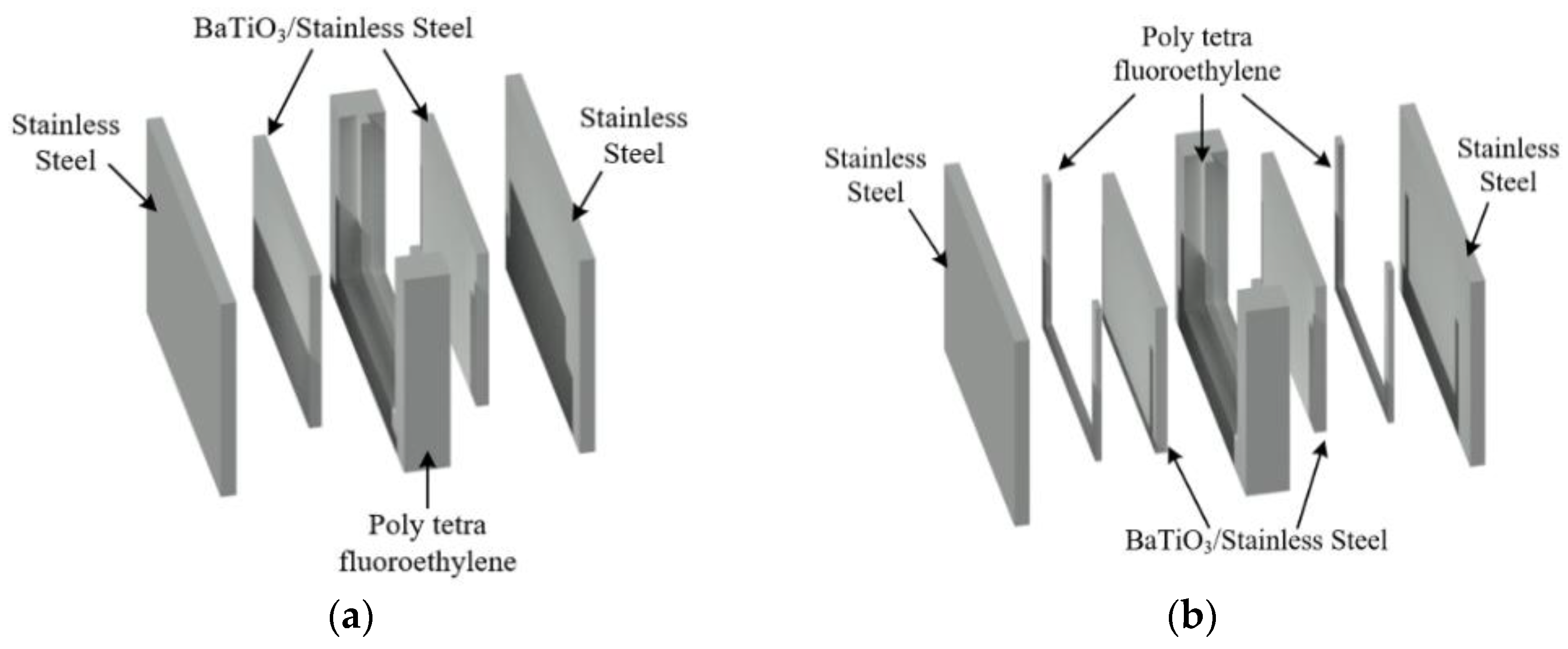
In practice, it was not possible to achieve ideal contact between the BaTiO3 plates and the electrodes, which created a gap between the two materials. The existence of these gaps formed a very thin layer of air, which triggered the occurrence of dielectric barrier discharge (DBD) between the BaTiO3 layer and the electrodes when external high voltage was applied. Once the DBD started, the actual electric field in the treatment region collapsed. In order to avoid this situation, two approaches were adopted in the present study, as demonstrated in Figure 2.
(a) The BaTiO3 ceramic plates and the stainless-steel plates were joined together using silver paste, which is a good conducting material. The air gaps between the plates were eliminated by doing so. The width of the treatment region was set to 5 mm.
(b) The gaps between the plates were extended intentionally and would be filled with the same liquid sample. Therefore, three treatment regions were created, namely G (between the ground electrode and a BaTiO3 plate), M (between the two BaTiO3 plates), and H (between the HV electrode and a BaTiO3 plate). The three regions shared the same static electric field strength, which can be approximated as:
E 0 U 0 / z G + z M + z H
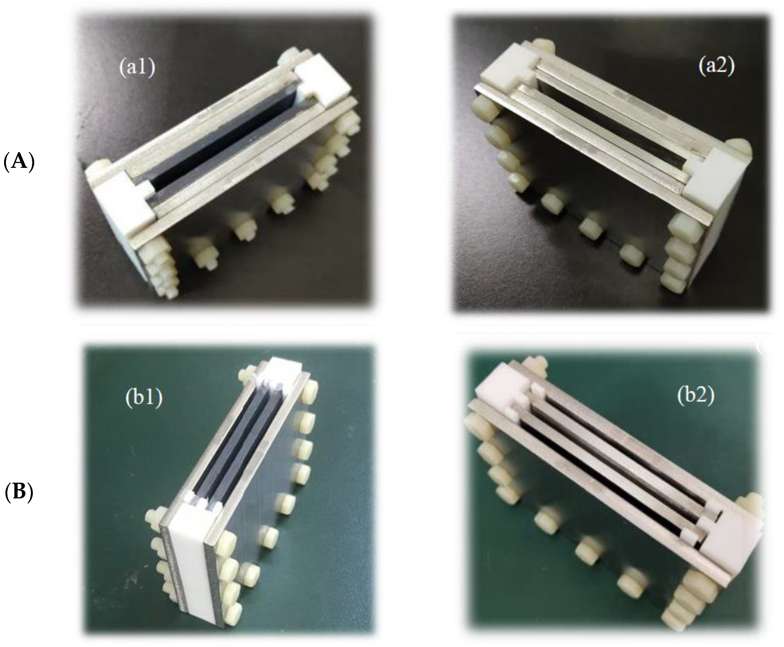
where z G , z M and z H are the width of the three regions, respectively, and which were all set to 3 mm in the present study. Other supporting and spacing structures of the PEF chambers were made out of Polytetrafluoroethylene (PTFE). Additional PEF chambers with identical geometry were assembled, with BaTiO3 plates replaced by stainless-steel plates in order to provide reference results for the BaTiO3 ceramic chambers. Figure 3 shows the actual assembled chambers.

2.2. PEF System Setups

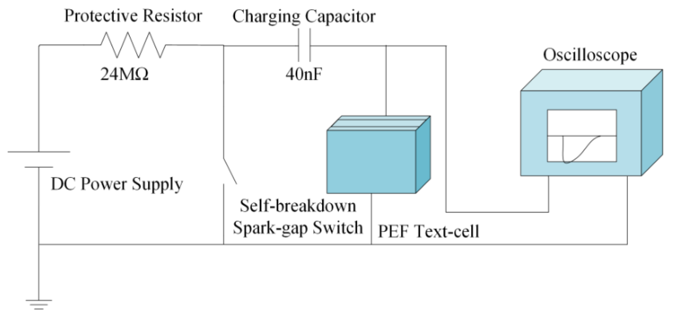
An exponential decay pulse-generating system was constructed to supply HV impulses for the present study. This RC-based pulse-generating system, as shown in Figure 4, consisted of a DC-positive high voltage supply (TRC2020, Dalian Teslaman Technology Co. Ltd., Dalian, China), a 24 MΩ protective resistor, a self-breakdown spark-gap switch and a 40 nF HV charging capacitor. The DC power supply had a 50 W rated power with a maximum output voltage of 50 kV and maximum current output of 1 mA. The breakdown voltage of the switch was controlled by adjusting the distance of the inter-electrodes gap, which consequently controlled the voltage across the PEF chamber. The pulse repetition rate was regulated by adjusting the current output of the DC supply. A monitoring system, which consisted of a voltage probe (P6015A, Tektronix, Beaverton, OR, USA), a current probe (Pearson 6585), and a digital oscilloscope (TDS2024C, Tektronix, Beaverton, OR, USA), was used to monitor and record the voltage and current signals during the PEF treatment.

2.3. Preparation of Yeast Suspension

Yeast Saccharomyces cerevisiae was used in the present study. A total of 0.5 g of S. cerevisiae was cultured in 100 mL sterilized Yeast Extract Peptone Dextrose Medium (YEPD) solution at 30 °C in a shaking incubator, which rotated at 120 rpm. After incubating for 24 h, the yeast suspension was diluted into 500 mL using sterilized deionized water which reduced the conductivity of the suspension to around 86 μS/cm. The resulting yeast suspension was used for the PEF treatment at a population density of ~106 colony forming units per milliliter (CFU/mL). Triplicate tests were conducted for each experiment.

2.4. Assessment of PEF Inactivation

The prepared yeast suspension was put into the PEF chambers and subjected to 2000 high voltage impulses at 20 kV/cm electric field strength and a pulse repetition rate of 1 pulse per second (1 pps). As discussed in Section 2.1, the approximate static electric field strength differed within treatment regions of different PEF chambers. The actual voltage applied to the PEF chambers was calculated according to Equations (2) and (3). The population density of yeast cells in the suspension was calculated before and after the treatment to evaluate the sterile rate of the PEF treatment. The spread-plate method was used to plate 0.1 mL of the sample onto YEPD agar plates. The agar plates were then incubated at 30 °C for 24 h in a stationary incubator before the number of yeast colonies were counted. The sterile rate can be calculated according to the following equation:
Sterile   Rate = N C N T N C × 100 %
where NC is the number of yeast colonies from the control (untreated) group and NT is the number of yeast colonies from the PEF-treated group.

2.5. Determination of Metallic Ions and (∙OH) Concentrations

In the experiments conducted using type (b) PEF chambers, measurements of metallic ions and (∙OH) concentrations were taken. The concentrations of iron and Ba2+ ions in the yeast suspension sample were measured using an ICP-MS (NexION 350X, PerkinElmer, Waltham, MA, USA) following standard operation procedures.
As a short-lived, highly reactive substance, extra trapping agents were needed in order to quantify the concentration of (∙OH) hydroxyl radicals [18]. In the present study, methylene blue (C16H18CIN3S) was selected as the trapping agent. This solution was put into different PEF chambers before undergoing the same PEF treatment. The absorbance at 664 nm of the treated methylene blue solution was then measured using an UV-visible spectrophotometer (UVmini-1240, Shenzhen Lxyee Electronic Technology Co., Ltd., Shenzhen, China). The concentration of the (∙OH) in treated samples was evaluated by comparing their respective absorbances with the standard absorbance curve.

3. Results and Discussion

3.1. Voltage and Current Waveforms

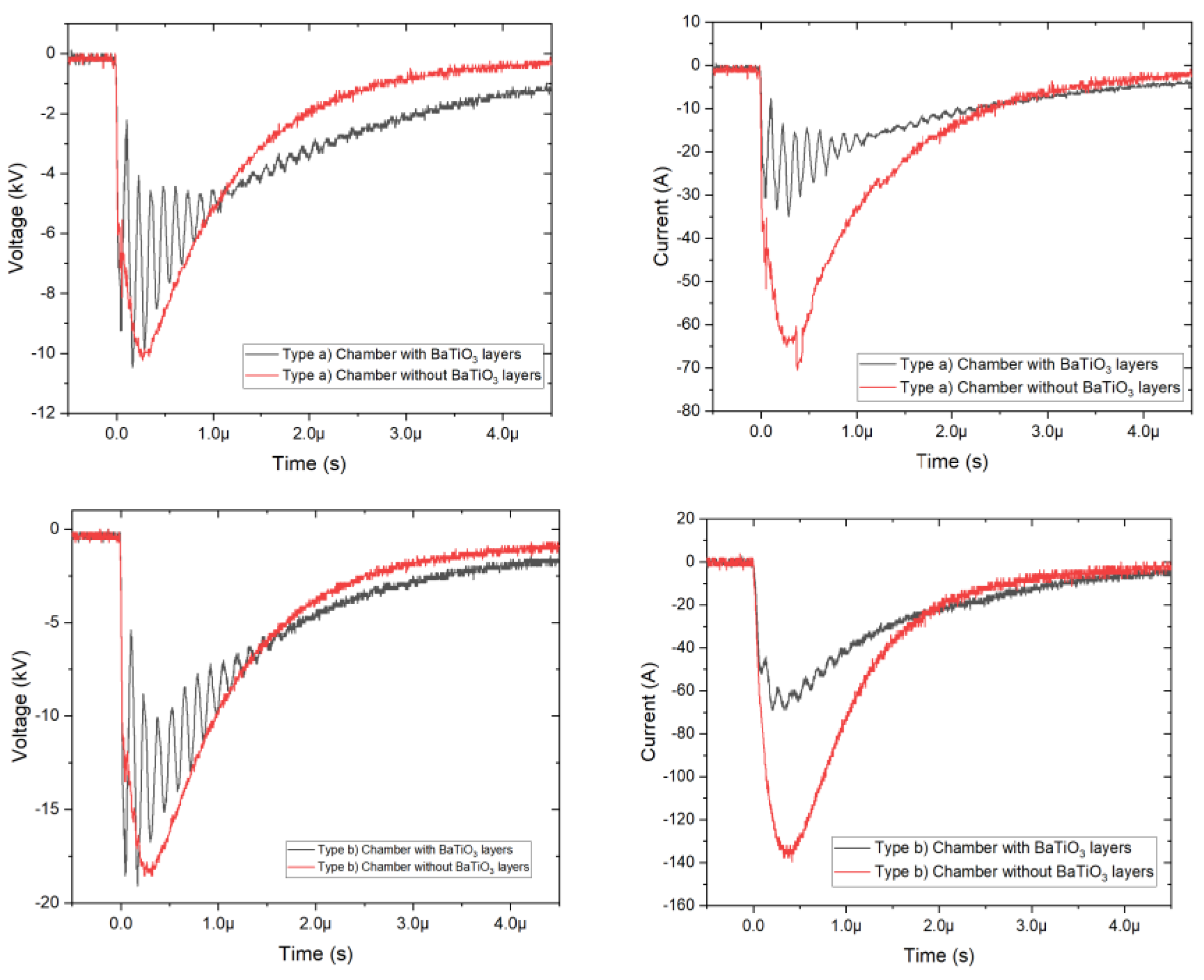
As mentioned in Section 2.2, the voltage and current waveforms were monitored and recorded during PEF treatments using different chambers. As demonstrated in Figure 5, the voltage waveforms had simple, exponentially decaying waveshapes as expected from a RC-based pulse generator, despite some oscillations being observed in chambers with BaTiO3 layers. However, the current waveforms indicate an interesting phenomenon: the current waveforms generally followed the similar tendency as the voltage waveform in the same PEF chamber. However, the peak current in chambers with BaTiO3 layers was roughly half of that obtained in the traditional stainless-steel chambers.
As PEF chambers with/without the BaTiO3 layers shared the same topology and geometry parameters, this result indicated that the voltage across the suspension in the BaTiO3 chambers was around 50% of that in the stainless-steel chambers. Therefore, the field strengths across the same amount of suspension should also have the same ratio for the two types of chambers. As a result, an inferior sterile rate should be expected in the PEF chambers with the dielectric layers.
This unusual phenomenon revealed that something different was happening in the chamber with BaTiO3 layers during PEF treatment, which could be the Maxwell–Wagner field relaxation process or some unknown chemical–electrical reaction. Such a phenomenon was not reported in [17], where a similar indirect-contact PEF chamber was assembled and used in practical experiments. Therefore, further investigation of the causes of this phenomenon, together with the direct measurement of electric field strength inside the PEF chamber, could be helpful for understanding the exact transient processes and PEF mechanisms involved in indirect-contact PEF chambers.

3.2. Effects on Sterile Rate

The sterile rates of the yeast suspension in different PEF chambers and treatment regions, and the statistical analyses of the results are shown in Figure 6 and Table 1, respectively. As can be seen from the figure, literally no inactivation of yeast was observed in PEF treatment using all the chambers with BaTiO3 plates. As a comparison, an average of 63% sterile rate was achieved in the type a) chamber and all regions in the type b) chamber when the BaTiO3 plates were replaced by stainless steel. The statistical analysis also suggested that the sterile rate of the BaTiO3 groups was statistically no different from the untreated sample, but was significantly different (with 99% confidence) from the stainless-steel groups. The results conflicted with the experimental results reported in [17], in which ceramic material was also used as the dielectric barriers. However, the electric field strength used in [17] was more than six times the field strength used in the present study.
As reported in [16], the transient electric field strength in the treatment region could be affected by the Maxwell–Wagner field relaxation process in PEF chambers with dielectric barriers. According to an analytical transient model developed in [16], the electric field strength inside the treatment region could collapse quickly due to the Maxwell–Wagner surface-polarization mechanism. In addition, the peak field strength and the peak trans-membrane potential could also be significantly lower than that in a traditional conducting PEF chamber, which could explain why successful inactivation was achieved in [17] while no inactivation was observed in the present study. Based on the analytical model in [16], and the practical experimental results obtained in [17] and the present study, it could be concluded that PEF inactivation of microorganisms using chambers with dielectric barriers may be possible, but significantly higher nominal electric field strength would be required due to the Maxwell–Wagner field relaxation process.

3.3. Effects on Concentrations of Metallic Ions

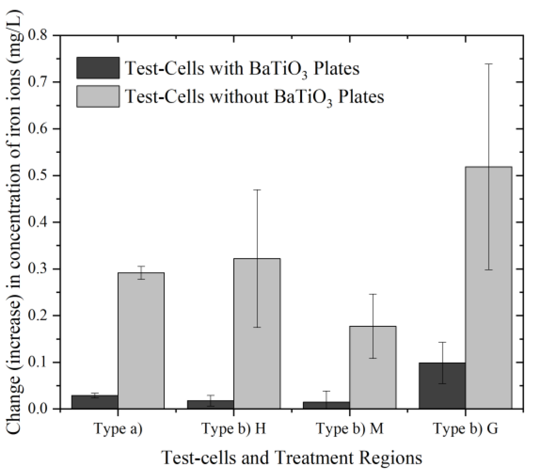
Figure 7 and Figure 8 demonstrate the increase of iron and Ba2+ ion concentrations in the yeast solution samples respectively. The statistical analyses of these results are shown in Table 2 and Table 3, respectively. It can be seen from Figure 6 that the presence of the BaTiO3 plates limited the release of iron ions significantly. Statistically, the changes in the concentration of iron ions in all regions were significantly different (with at least 90% confidence) in the BaTiO3 groups compared with the respective regions in the stainless-steel groups. The concentration of iron ions in the yeast suspension samples were significantly lower in all the regions in the chambers with BaTiO3 layers compared with the traditional stainless-steel chambers. In particular, no iron ions were produced in the samples in region M of the type b) chamber, which was formed by the two BaTiO3 plates. The results confirmed that the application of dielectric layers could effectively restrict electrochemical reactions between the metallic electrodes and the liquid samples and limit the generation of resulting metallic ions.
It can also be noted that in region G of the type b) chambers, where the liquid samples were in contact with the ground electrodes, more iron ions were produced during the PEF process compared with other regions in both chambers with/without the dielectric layer. This phenomenon suggested that the electrochemical reactions around the ground electrodes were more intense in the present study. It is widely accepted that reactions on the anode surface are more severe than those on the cathode surface when high voltage impulses are applied [19,20,21]. In the present study, the pulse-generating system produced negative impulses, as can be seen from Figure 4, which made the ground electrodes effectively the anode. Therefore, the finding obtained in the present study is in line with the experimental results reported in other studies.
However, as can be seen from Figure 8, significant amount of Ba2+ ions were detected in the type b) chambers after the PEF treatment. On average, the concentration of Ba2+ ions increased by 1.1 mg/L in the 3 regions of the chambers with a BaTiO3 layer. However, such changes in the Ba2+ ion concentration were not observed in the type a) chamber with BaTiO3 layers, as can be seen from Figure 8 and Table 3. This result suggested that reactions involving the BaTiO3 ceramic could have occurred during the PEF treatment, causing the release of barium ions. The exact type of reaction is unclear and further investigation would be required to identify its mechanisms. However, the possibility of such a reaction, involving dielectric material, needs to be considered in future chamber designs and material selection in order to avoid unnecessary contamination.

3.4. Effects on (∙OH) Concentrations

As discussed in Section 1, the existence of hydroxyl radicals can reflect the occurrence of electrochemical reactions during the PEF process. Studies also indicate that this substance can play an important part in the inactivation of microorganisms in the liquid [22,23]. Therefore, an approach was adapted to measure the (∙OH) concentration as described in Section 2.4; the results and its statistical analysis are displayed in Figure 9 and Table 4, respectively. The results show that the existence of (∙OH) was observed in the yeast suspension in both type b) chambers. The contents of the (∙OH) were more notable in the chamber with BaTiO3 barriers, but the difference between the stainless-steel groups and BaTiO3 groups were not so significant statistically. This result provided another evidence that some PEF-triggered reactions had taken place, in which BaTiO3 plates were involved.
It has long been suggested that the PEF inactivation of microorganisms could be the combined effect of the electric field and PEF-induced by-products, such as metallic ions and free radicals [8,24]. The experimental results from the present study indicated that while both metallic ions and hydroxyl radicals appeared in both BaTiO3 and stainless-steel chambers after PEF treatment, inactivation of yeast was only achieved in the stainless-steel chamber. Considering that the actual transient electric field strength inside the chamber with BaTiO3 layer could be much lower, as discussed in Section 3.1, it can be concluded that the dominant PEF inactivation mechanism was the application of intensive electric field in the present study.

4. Conclusions

In the present study, indirect-contact PEF chambers with dielectric layers made of BaTiO3 ceramic were designed and constructed. PEF inactivation of yeast S. cerevisiae using these chambers, and its effects on the metallic ions and hydroxyl radical concentration in the liquid samples, were investigated. The results obtained in the present study show that the inactivation of yeast in the indirect-contact chambers was unsatisfactory when a 20 kV/cm static electric field strength was applied. Based on the modeling analysis and experimental results of other studies, a much higher external static electric field would be required when this type of chamber structure is adopted due to the Maxwell–Wagner field relaxation process. The unusual current pattern observed in the PEF chamber with BaTiO3 ceramic plates also suggested that this field relaxation process could have taken place. Direct measurement of the transient electric field strength inside the chamber would be helpful in confirming this phenomenon in future research.
It was confirmed in the present study that the presence of the dielectric barriers could limit the occurrence of electrochemical reactions between the liquid and the metallic electrodes during the PEF process. However, evidence suggests that other reactions involving the ceramic layers also took place during the PEF treatment in the present study, and that barium ions and hydroxyl radical were produced as a result. Further studies are required to identify the exact type of reaction observed in the present study.
The experimental results from the present study also indicates that the main factor that inactivates the microorganisms during the PEF process is the intensive external electric field. Free radicals and metallic ions, without the continuous presence of sufficient electric field strength, cannot cause the death of microbial cells in the liquid suspension.

Author Contributions

Conceptualization, S.Q. and S.H.; methodology, S.Q.; validation, J.M. and J.H.; formal analysis, Z.Z.; investigation, Z.Z. and J.H.; resources, S.H.; data curation, Z.Z. and J.H; writing—original draft preparation, S.Q.; writing—review and editing, S.H. and J.M.; visualization, J.H.; supervision, S.H.; project administration, S.Q.; funding acquisition, S.Q. All authors have read and agreed to the published version of the manuscript.

Funding

This research was funded by Guangxi Natural Science Foundation Program, under Grant 2018GXNSFBA138055.

Institutional Review Board Statement

Not applicable.

Informed Consent Statement

Not applicable.

Data Availability Statement

Not applicable.

Conflicts of Interest

The authors declare no conflict of interest.

References

  1. Toepfl, S.; Heinz, V.; Knorr, D. High intensity pulsed electric fields applied for food preservation. Chem. Eng. Process 2007, 46, 537–546. [Google Scholar] [CrossRef]
  2. Zimmermann, U. Electrical breakdown, electropermeabilization and electrofusion. Rev. Physiol. Biochem. Pharmacol. 1986, 105, 175–256. [Google Scholar]
  3. Brito, P.S.; Canacsinh, H.; Mendes, J.P.; Redondo, L.M.; Pereira, M.T. Comparison between monopolar and bipolar microsecond range pulsed electric fields in enhancement of apple juice extraction. IEEE Trans. Plasma Sci. 2012, 40, 2348–2354. [Google Scholar] [CrossRef]
  4. Jaeger, H.; Meneses, N.; Knorr, D. Impact of PEF treatment inhomogeneity such as electric field distribution, flow characteristics and temperature effects on the inactivation of E. coli and milk alkaline phosphatase. Innov. Food Sci. Emerg. Technol. 2009, 10, 470–480. [Google Scholar] [CrossRef]
  5. Guionet, A.; Fujiwara, T.; Sato, H.; Takahashi, K.; Takaki, K.; Matsui, M.; Tanino, T.; Ohshima, T. Pulsed electric fields act on tryptophan to inactivate α-amylase. J. Electrost. 2021, 112, 103597. [Google Scholar] [CrossRef]
  6. Ohshima, T.; Tamura, T.; Sato, M. Influence of pulsed electric field on various enzyme activities. J. Electrost. 2007, 65, 156–161. [Google Scholar] [CrossRef]
  7. Min, S.; Evrendilek, G.A.; Zhang, H.Q. Pulsed electric fields: Processing system, microbial and enzyme inhibition, and shelf life extension of foods. IEEE Trans. Plasma Sci. 2007, 35, 59–73. [Google Scholar] [CrossRef]
  8. Jayaram, S.H. Sterilization of liquid foods by pulsed electric fields. IEEE Electr. Insul. Mag. 2000, 16, 17–25. [Google Scholar] [CrossRef]
  9. Zhang, Q.; Barbosa-Cánovas, G.V.; Swanson, B.G. Engineering aspects of pulsed electric field pasteurization. J. Food Eng. 1995, 25, 261–281. [Google Scholar] [CrossRef]
  10. Narsetti, R.; Curry, R.D.; McDonald, K.F.; Clevenger, T.E.; Nichols, L.M. Microbial inactivation in water using pulsed electric fields and magnetic pulse compressor technology. IEEE Trans. Plasma Sci. 2006, 34, 1386–1393. [Google Scholar] [CrossRef]
  11. Qin, B.-L.; Zhang, Q.; Barbosa-Cánovas, G.V.; Swanson, B.G.; Pedrow, P.D. Inactivation of microorganisms by pulsed electric fields of different voltage waveforms. IEEE Trans. Dielectr. Electr. Insul. 1994, 1, 1047–1057. [Google Scholar]
  12. Aronssona, K.; Lindgrena, M.; Johanssonb, B.R.; Rönner, U. Inactivation of microorganisms using pulsed electric fields: The influence of process parameters on Escherichia coli, Listeria innocua, Leuconostoc mesenteroides and Saccharomyces cerevisiae. Innov. Food Sci. Emerg. Technol. 2001, 2, 41–54. [Google Scholar] [CrossRef]
  13. Lubicki, P.; Jayaram, S. High Voltage Pulse Application for the Destruction of the Gram-negative Bacterium Yersinia enterocolitica. Bioelectrochem. Bioenerg. 1997, 43, 135–141. [Google Scholar] [CrossRef]
  14. Qin, S.; Timoshkin, I.; Maclean, M.; MacGregor, S.; Wilson, M.; Given, M.; Wang, T.; Anderson, J. TiO2-Coated Electrodes for Pulsed Electric Field Treatment of Microorganisms. IEEE Trans. Plasma Sci. 2016, 44, 2121–2128. [Google Scholar] [CrossRef] [Green Version]
  15. Tanino, T.; Hirosawa, M.; Moteki, R.; Matsui, M.; Ohshima, T. Engineering of pulsed electric field treatment using carbon materials as electrode and application to pasteurization of sake. J. Electrost. 2020, 104, 103424. [Google Scholar] [CrossRef]
  16. Timoshkin, I.V.; MacGregor, S.J.; Fouracre, R.A.; Crichton, B.H.; Anderson, J.G. Transient electrical field across cellular membranes: Pulsed electric field treatment of microbial cells. J. Phys. D Appl. Phys. 2006, 39, 569–603. [Google Scholar] [CrossRef]
  17. Novac, B.M.; Banakhr, F.A.; Smith, I.R.; Pecastaing, L. Demonstration of a novel pulsed electric field technique generating neither conduction currents nor Joule effects. IEEE Trans. Plasma Sci. 2014, 42, 216–228. [Google Scholar] [CrossRef] [Green Version]
  18. Peralta, E.; Roa, G.; Hemandez-Servin, J.A. Hydroxyl radicals quantification by UV spectrophotometry. Electrochim. Acta 2014, 129, 137–141. [Google Scholar] [CrossRef]
  19. Roodenburg, B.; Morren, J.; Berg, H.E. Metal release in a stainless steel pulsed electric field (PEF) system: Part II. The treatment of orange juice; related to legislation and treatment chamber lifetime. Innov. Food Sci. Emerg. Technol. 2005, 6, 337–345. [Google Scholar] [CrossRef]
  20. Saulis, G.; Riseviciene, R.; Snitka, V. Increase of the roughness of the stainless-steel anode surface due to the exposure to high-voltage electric pulses as revealed by atomic force microscopy. Bioelectrochemistry 2007, 70, 519–523. [Google Scholar] [CrossRef] [PubMed]
  21. Rodaite-Riseviciene, R.; Saule, R.; Snitka, V. Release of Iron Ions From the Stainless Steel Anode Occurring During High-Voltage Pulses and Its Consequences for Cell Electroporation Technology. IEEE Trans. Plasma Sci. 2014, 42, 249–254. [Google Scholar] [CrossRef]
  22. Bai, M.D.; Bai, X.; Zhang, Z. Treatment of Red Tide in Ocean Using Non-Thermal Plasma Based Advanced Oxidation Technology. Plasma Chem. Plasma Process. 2005, 25, 539–550. [Google Scholar] [CrossRef]
  23. Takatsuji, Y.; Ishikawa, S.; Haruyama, T. Efficient sterilization using reactive oxygen species generated by a radical vapor reactor. Process Biochem. 2017, 54, 140–143. [Google Scholar] [CrossRef]
  24. Hulsheger, H.; Niemann, E.G. Lethal Effect of High Voltage Pulses on E. coli K12. Radiat. Eniron. Biophys. 1980, 18, 281–288. [Google Scholar] [CrossRef] [PubMed]
Figure 1. Concept of a PEF chamber with dielectric layers.
Processes 10 02432 g001
Figure 2. Schematic of the PEF chamber designs. (a) Chamber with BaTiO3 plates and electrodes joined together using silver paste; (b) Chamber with extended gaps between BaTiO3 plates and electrodes.
Processes 10 02432 g002
Figure 3. Assembled PEF chambers. (A) Chambers with BaTiO3 plates and electrodes joined together by silver paste. (a1): with BaTiO3 plates; (a2): BaTiO3 plates replaced by stainless steel plates; (B) Chambers with extended gaps between BaTiO3 plates and electrodes. (b1): with BaTiO3 plates; (b2): BaTiO3 plates replaced by stainless steel.
Processes 10 02432 g003
Figure 4. Circuit diagram of the PEF system.
Processes 10 02432 g004
Figure 5. Actual voltage and current waveforms obtained during PEF treatment using different PEF chambers.
Processes 10 02432 g005
Figure 6. Effects of PEF treatment on the sterile rate of yeast using different types of chambers. Error bars show standard deviation (n = 3).
Processes 10 02432 g006
Figure 7. Effects of PEF treatment on the concentration of iron ions in yeast suspension using different types of chambers. Error bars show standard deviation (n = 3).
Processes 10 02432 g007
Figure 8. Effects of PEF treatment on the concentration of Ba2+ ions in yeast suspension using different types of chambers. Error bars show standard deviation (n = 3).
Processes 10 02432 g008
Figure 9. Effects of PEF treatment on the concentration of (∙OH) in yeast suspensions using different types of chambers. Error bars show standard deviation (n = 3).
Processes 10 02432 g009
Table 1. Statistical analysis of the experimental results of yeast sterilization (%).
ChamberRegionsMeanSDSEMSignificant Difference
(From Control Group)
Significant Difference
(From Stainless Steel Group)
At 0.05At 0.1At 0.01
BaTiO3Type a)0.730.4070.235NoYesYes
Type b) H1.141.2550.724NoNoYes
Type b) M4.122.6801.547NoNoYes
Type b) G5.401.8641.076YesYesYes
Stainless steelType a)64.602.4851.435YesYesN/A
Type b) H56.865.0072.891YesYesN/A
Type b) M62.002.2381.292YesYesN/A
Type b) G62.966.8163.935YesYesN/A
Table 2. Statistical analysis of the experimental results of iron ions concentration (mg/L).
ChamberRegionsMeanSDSEMSignificant Difference
(From Control Group)
Significant Difference
(From Stainless Steel Group)
At 0.05At 0.1At 0.05At 0.1
BaTiO3Type a)0.0290.0050.003YesYesYesYes
Type b) H0.0180.0110.007NoNoNoYes
Type b) M0.0150.0240.014NoNoNoYes
Type b) G0.1000.0440.026NoYesNoYes
Stainless steelType a)0.2920.0140.008YesYesN/AN/A
Type b) H0.3220.1480.085NoYesN/AN/A
Type b) M0.1770.0690.040YesYesN/AN/A
Type b) G0.5190.2200.127NoYesN/AN/A
Table 3. Statistical analysis of the experimental results of Ba2+ ion concentration (mg/L).
ChamberRegionsMeanSDSEMSignificant Difference
(From Control Group)
Significant Difference
(From Type a) Group)
At 0.05At 0.1At 0.01At 0.05
BaTiO3Type a)0.0050.0030.002NoNoN/AN/A
Type b) H1.2170.4340.251YesYesNoYes
Type b) M1.1010.2480.143YesYesNoYes
Type b) G0.9550.1760.102YesYesNoYes
Table 4. Statistical analysis of the experimental results of hydroxyl radical concentration (mol/L).
ChamberRegionsMeanSDSEMSignificant Difference
(From Control Group)
Significant Difference
(From Stainless Steel Group)
At 0.05At 0.1At 0.05At 0.1
BaTiO3Type b) H0.0100.0220.012YesYesNoNo
Type b) M0.0670.0300.017NoYesNoNo
Type b) G0.1080.0200.011YesYesNoYes
Stainless steelType b) H0.1060.0230.013YesYesN/AN/A
Type b) M0.1250.0380.022YesYesN/AN/A
Type b) G0.1840.0410.024YesYesN/AN/A
Publisher’s Note: MDPI stays neutral with regard to jurisdictional claims in published maps and institutional affiliations.