Abstract
Rough processing of iron ore employs dry methods which means that equipment is tuned to process large particles, but fine magnetic material less than a few tenths of a millimeter in size is not separated as efficiently. The relevance of this study is determined by the fact that dry beneficiation waste contains recoverable iron-bearing magnetite of commercial value. Commercial justification of waste beneficiation is associated with mining and grinding costs that are already included in the prime cost of the commercial concentrate. The future of tailings retreatment prospects depends on technology and efficiency of the employed equipment, the development of which is the subject of this paper. At first stage, fine iron is recovered by air sizing, with pitched curtain air classifiers embedding simple design and high performance. Powder materials were magnetically separated by a manufactured drum-type separator in which, to increase the separation efficiency, the process was performed at increased drum rotation speeds using --B magnets and a drum made of electrically non-conductive materials. The separator performance was determined for various rotation speeds of the drum. Research has proven that a multi-stage magnetic separation with a consequent increase in drum rpm is reasonable. A new cascade separator was manufactured and tested for this purpose. It is shown that iron-containing ore tailings beneficiation is optimal without any additional grinding.
1. Introduction
Iron-containing ore beneficiation includes several stages. For example: crushing to −30 mm size class and rough magnetic separation, further crushing of the recovered magnetic product to −10 mm size class and final magnetic metal content upgrading. All operations use dry methods. Such an approach will concentrate relatively large particles of the material for which magnetic separators are fitted, while smaller magnetic particles, e.g., 0.3–0.5 mm, are separated less efficiently. Therefore, dry beneficiation waste-tailings contain fine magnetite particles of commercial value. It is commercially feasible to recover iron from process waste, because ore mining and processing costs are already included in the commercial concentrate cost. Efficient classification methods for large quantities of tailings to recover fine particles mechanically and efficient magnetic beneficiation machines for such products with low magnetic product grade will be a practical solution. Total iron recovery can be increased without additional grinding and large financial costs. Opportunities in this area are defined by the process equipment. As already noted, the first stage will be fine grain separation from a large quantity of tailings. Ore processing employs screening as the main classification method [1,2,3,4,5,6]. It involves dispersing ore materials over classification sieves and screens with sized holes. However, screening of particles below 1 mm is unreasonable because their specific output would be very low. Such fine dry materials are more reasonably separated with air classification equipment [7,8,9,10,11,12,13,14,15]. For example, 20 t/hm specific load for gravity air screens can be achieved, but it would be 0.2 t/hm for the near-mesh size of 0.1 mm [15]. Among air classification equipment, the pitched curtain air classifier has applicative interest [14]. They embed high performance and material advantages in manufacturing and application. The present study uses these classifiers to isolate fine grain from wastes of magnetic separation of magnetite ores. After separation of fine-grained material, further beneficiation is restricted to the procedure of dry magnetic separation. Studies [16,17] propose that magnetic separators should be used for beneficiation of such materials. Conventional drum separation technology involves magnetic particles being gravitated to the drum and non-magnetic particles being discarded as waste by centrifugal force. The separator [16] works in the opposite way: magnetic parties are removed from the belt bent around the rotating drum and are gravitated to the drum while the waste rock is left on the belt. The advantage is that with conventional option, fine magnetic particles are prone to magnetic flocculation catch and gravitate the non-magnetic particles to the drum, which aggregates impurifying the concentrate. The effect when the original product is initially on the belt and iron-bearing particles are gravitated to the drum in the magnetic field making some distance is considerably reduced. Another offered method [17] employs air and magnetic separation to separate particles by their magnetic properties. Here, the fine material is loosened and dispersed to make the dust mixture. The dust mixture blown with constant speed into an inhomogeneous magnetic field is used for magnetic separation. This paper searches for ways to minimize production costs. One of the oldest types of magnetic separator is a magnetic drum separator which is unconditionally widely used for industrial purposes [18]. It is simpler in design and manufacture compared to the previously proposed separators [16,17] for beneficiation of crushed magnetite ores. Therefore, here, we consider the use of less costly drum magnetic separators, modernized to work with waste from the dry processing of such ores. Cascaded drum magnetic separators are proposed, which allow to achieve comparable results with [16,17] on the beneficiation of iron-containing ore magnetic separation waste.
2. Materials and Methods
The following material was used for research: iron concentrate from the Bapy mine (Kazakhstan) with 52 percent average iron grade, 2.65 g/cm quartzite and tailings—dry process waste of the same mine. Fine and rough particles were separated with air classification. The tailings screening laboratory unit is shown in Figure 1A. The laboratory gravitational air classifier (1) is geometrically similar to that described in [14] and is shown in Figure 1B. Each of the six inlet channels is 50 mm wide. The curtain thickness is 0.5 mm, the gap between curtain blades is 25 mm. The equipment operation principle is as follows. The material is fed with the material feeder (2) on the top curtain blade. Air flow is produced by the high-pressure ventilator (7). Rough particles are rolled down from pitched curtain surfaces and fine particles are blown with air to the classifier (1). Rougher particles of this product fall on the fine particle collector (4) and the remaining particles are deposited in the cyclone (3) and dust particles are collected by the hose filter (5). The magnetic separator was built for beneficiation research. The particle with m mass on the rotating drum surface is exposed to two main forces: attraction forces from magnets:
where —coefficient of magnetization (m/kg), —magnetic constant equal to 1.256 × 10 hn/m and the centrifugal force proportional to the drum rpm and R radius:
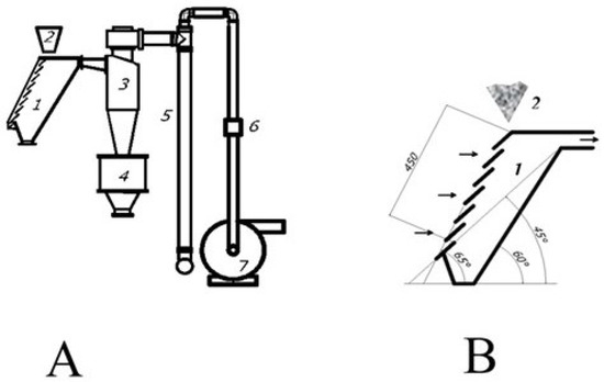
Figure 1.
Layout of the laboratory tailings screening equipment (A) pitched curtain air classifier design (B): 1—air classifier; 2—material feeder; 3—air cyclone; 4—fine particle collector; 5—hose filter; 6—flowmeter; 7—high pressure ventilator.
Particles are kept on the drum when . Separation is done at the breaking point of this condition. As it has already been noted, waste rock particles impurify the final concentrate during dry processing of fine magnetic particles. The situation is worsened when the magnetite grade in powder is low. The situation can be improved by increasing the separator drum speed, sufficiently increasing the centrifugal and improving removal of the waste rock. To satisfy this condition, --B magnets were used in the separator. With 0.1 m drum radius, the rotation speed is above 1000 rpm. To manufacture the drum, it was proposed [16] that those non-conducting materials should be used to avoid Foucault currents while rotating a conducting material in a high-variable magnetic field.
These currents resist rotation and heat a conducting drum reducing magnetic forces applied to the particles. This study uses a plastic drum coated with rubber to reduce abrasion. This drum, when used, sufficiently reduces power consumption as a low-power electric motor can be used. High rotation speed makes the drum physically rigid. It is desirable for fine particle magnetic separation to have a small layer of separated fine particles on the drum. Then, all particles in the magnetic field will be subjected to approximately the same average magnetic force. Separation quality will improve. The equipment performance is not reduced sufficiently thanks to high drum speed. The material size distribution was determined by screen test using the available screen set with mesh size: 0.063; 0.125; 0.250; 0.5; 1; 2; 4 mm.
3. Results and Discussion
The study in [16] used the artificial magnetite concentrate and quartzite mix to determine the magnetic separator specification experimentally. This method was used in this study as well. The required mix was obtained as follows. The processed ore of −10 mm size with 52 percent average iron grade was crushed and ground to (−0.1) mm size. The required quantity of 60 percent iron concentrate was produced by a multi-stage cleaner separation using the laboratory magnetic separator being studied. We note that this ore is difficult to process, and a finer grinding is required to increase Fe grade. The mix was prepared using the produced concentrate and the quartzite powder. The original quartzite was ground with a jaw crusher and fine particles were recovered with the pitched curtain air classifier (Figure 1) at 2 m/s air flow rate. The product size distribution recovered with the air classifier can be determined if the original material size distribution is known by the size and the fine size recovery rate :
The above-mentioned study of the pitched curtain air classifiers obtained the fine size recovery rate experimentally for quartzite separation approximated by Plitt theoretical distribution [15]:
where the Euler–Mayer criterion can be used to calculate the separation efficiency factor p [14]:
Here, , , are average close-cut particle sizes mixed with fine-size product of 25 percent, 50 percent, 75 percent, correspondingly. The parameter p determines the separation sharpness. This approach can characterize the fine size recovery rate of the powder air separation with experimental values , , or and parameter p (5). Table 1 provides parameters of this function for 2 m/s; 2.5 m/s; 3 m/s air speeds and various flow concentrations (kg/m) of the powder mass per volume unit of air. The air speed was calculated using the air flow rate, i.e., using the flow meter 6 (Figure 1) and total cross section area of inlet channels (75 cm).

Table 1.
Fine size recovery rate.
To study the characteristics of the drum magnetic separator, an artificial mixture was produced. In a multi-stage mode, 60.6 percent Fe concentrate with a grain size of less than 0.1 mm was produced from refractory ore of the Bapy mine (Kazakhstan). An artificial mixture was prepared from concentrate and fine quartzite of the same class by thorough mixing in the following proportion of concentrate: = 1:9. The parameters of the mixture magnetic separation are presented in Table 2.
Table 2.
Artificial mix–magnetic separation parameters.
Tailings magnetic recovery research was completed for magnetite particles using magnetic separation tailings waste for size below 10–12 mm without any additional grinding. Figure 2 shows relative distribution of these particles by size x:
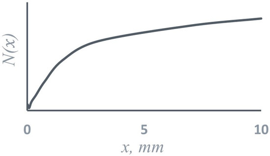
Figure 2.
Relative distribution of particles by size x in tailings.
Table 3 shows grade in various size classes.
Table 3.
grade in various size classes.
During the work, the research of tailings air classification was completed. Fine size recovery parameters were received and approximated by Plitt theoretical distribution (4). Data are shown in Table 4, where V represents air speed at the classifier inlet.
Table 4.
Fine size recovery parameters for magnetic separation waste.
A fine size was used for the magnetic separation experiment with V = 6 m/s air speed at the classifier inlet. Table 5 shows examples of the fine class processing at various drum speeds. The material feed rate was above 50 t/h per drum meter in length.
Table 5.
Fine size processing parameters.
Magnetic particles in experiments No. 1, 2 and 3 (Table 5) were reseparated, i.e., the cleaner separation was completed at 1300 rpm drum speed. Results are shown in Table 6 with the experiment number corresponding the number of the first magnetic separation product (Table 5).
Table 6.
Magnetic cleaner separation parameters.
Magnetic separation research was completed for the tailings shown in Table 3 and ground to (−0.125) mm size class. The data obtained with 1300 rpm drum speed are shown in Table 7.
Table 7.
Magnetic separation of various size particles ground to −0.125 mm size class.
When determining the magnetic separator properties (Table 2), the artificial mix load was 30 t/h per meter of the drum length at 1.33 g/cm bulk density. With drum speed increasing from 775 to 1300 rpm, the recovery was reduced slightly, but it exceeded 99 percent. In this case, the dust content of the concentrate was significantly reduced. This is achieved apparently due to the mix layer thickness on the drum being reduced by 40 percent and the centrifugal force being increased times. It can be concluded that this magnetic separator has high rates of extraction of small particles of magnetite less than 0.1 mm from the powder at their content of 10 percent.
Let us recap the tested magnetic separation waste produced during iron ore beneficiation. In the mining region, there are no adequate water supply sources, and the concentrate is produced by dry method only according to the following pattern. The extracted ore is crushed to a size below 30 mm and it undergoes the first stage of magnetic separation to 42–45 percent grade. This is followed by another operation of crushing the selected magnetic product to 10 mm size and the second magnetic separation stage. The final product of the mining and processing plant is 52 percent grade concentrate.
Therefore, such concentration is the goal for processing of the tailings, i.e., the waste of the second magnetic separation stage. Magnetic separation tailings processing technology begins with grading using the pitched curtain air classifier at the inlet air speed V = 6 m/s. Fine product percentage was 14 percent at the flow concentration kg/m. Magnetic separation of the recovered size (Table 5) showed that concentration in the processed material depends on the drum speed. concentration varies between 34.4 percent and 52.5 percent in the 520–1300 rpm range. The concentrate which produced 1040 and 1300 rpm (Table 5) has satisfactory quality. High drum speed of 1040 rpm and 1300 rpm corresponds to 10.8 m/s and 13.5 m/s surface linear speed. Material movement speed along the magnetic separator feeder tray is a dozen times lower. When such product contacts the drum surface, the drum experiences a strong physical impact appearing as higher abrasion. This effect can be reduced by decreasing the speed difference between the product and the drum. Experiments were completed at a significantly lower drum speeds for this purpose. These results are shown in Table 5. As we can see, grade is reduced to and 46 percent, thus being below the requirements. Therefore, one more magnetic separation run was completed for these products with the parameters shown in Table 6. The process products were fed to the cleaner separation at speeds below 1300 rpm. Concentrates with 55.9 and 57.8 percent grade were recovered. This is significantly higher than the set requirements. These results show that additional cleaner separation is required to optimize and achieve good results in powder material beneficiation with a low content of magnetic particles. For this purpose, a cascade separator was designed, with its layout shown in Figure 3. In the shown cascade separator, the top drum speed can be decreased, and the abrasion will decrease. When magnetic particles hit the bottom drum, they will have the top drum speed and the speed difference will be significantly reduced.
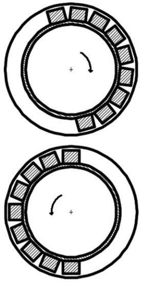
Figure 3.
Cascade separator layout.
In addition, load from the material on the bottom drum will decrease dramatically. Another advantage is that this layout is compact. Separators with more than two cascades can be designed. Let us explore the interaction area of two separators where they come closer to each other as shown on Figure 4.
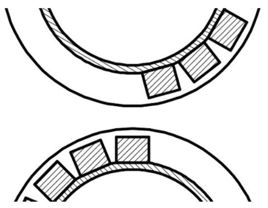
Figure 4.
Separator magnets interaction area.
Such a magnetic system can be calculated by solving the field problem of magnetostatics. Magnetic potential is equivalent to the effect of volume and surface magnetic charges. Magnets with a high anisotropy constant including strong magnets can be assumed to have a constant magnetization vector over the magnet volume which is equivalent to zero volume charge [19]. Consequently, sources of the field for “strong” magnets are surface charges. The magnetic system calculation is reduced to the problem of finding the potential field of uniformly charged surfaces. Since the system axial length significantly exceeds the magnetic system radius, the field can be considered as the plane parallel field. The magnetic potential at the coordinate point associated with the uniformly charged surface of width , with the center located at point can be calculated as follows [19]:
A field generated by a set of charged plates can be calculated by the superposition method. Then, the cumulative magnetic field intensity will be as follows:
We consider the simplified calculation pattern shown in Figure 5 in order to provide a qualitative assessment of the nature of the forces acting in the transition area between the separators. Here, the magnets are located on flat magnetic circuits.
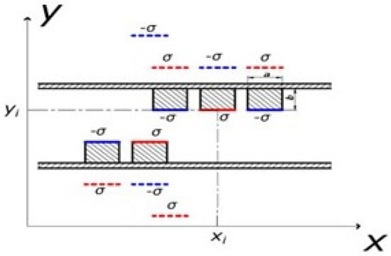
Figure 5.
Magnets on flat magnetic circuits 1 and 2. Dashed lines are lines of charges of opposite sign specularly reflected from isopotential surfaces.
Magnetic circuits are surfaces with the same potential, i.e., equipotential. To calculate the field, we use the spatial mirror image method, namely, if there is an equipotential surface, it causes another potential to appear, identified by the field of mirror-reflected charges of the opposite sign [19]. Mirrored charges are indicated by a dashed line in Figure 5. Red color indicates conditionally positive charges, and blue indicates conditionally negative charges. If we turn to the real picture shown in Figure 4, we can see that those equipotential surfaces, e.g., metal pipes with magnets, have the greatest effect on the nearest magnets of neighboring separators. This feature is shown in Figure 5. Appearing mirror charges from the neighboring equipotential surface is considered only for top and bottom system magnets which are closest to each other, as shown in Figure 5. We will calculate the magnetic system using the following formulas
Having found and , the magnetic force is calculated (1). This study includes a qualitative analysis of particle motion in space between separators. In this case, relative change in the magnetic force is interesting, therefore, the numeric value of constants is not of crucial importance (1). vertical force determining the area where particles detach from the drum surface area was calculated in order to understand the trajectory of particles in space between separators while moving from top and bottom separator.
where constants are combined with C parameter equal to 1. force calculations were completed during analysis of magnetic fields (12) for various magnet location and polarity layouts. Figure 6 provides one of the calculation options we considered. It was accepted for use in the equipment.
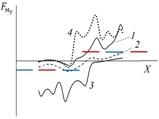
Figure 6.
Distribution of (1–4) force vertically applied to magnetite particle in the system with two separators. Horizontal line segments show location of 24 mm wide and 20 mm high magnets with colors indicating their polarities. The distance between the magnets is 30 mm.
In this calculation, the residual magnetic induction of the uppermost left magnet is assumed to be 3.5 times less than that of the remaining magnets, approximately corresponding to replacement of a neodymium magnet with a ferrite one. Curve 1 in Figure 6 shows change in force applied on magnetite particles in the vertical direction at 7 mm below the magnet surface. This value corresponds to distance from the separator magnetic system to the drum surface. Curve 2 is force applied along the middle line between top and bottom magnets. Curve 3 corresponds to force at 7 mm above the lower magnet surfaces. This figure implies that the particle attraction force becomes zero approximately at the midpoint of the ferrite magnet. The centrifugal force is active as well. Therefore, the particles detach from the top drum in the area where they cross the ferrite magnet. The material is in suspension. Here, particles are subject to the downward magnetic force, and the waste rock particles move under own inertia. Such a transition section improves the separation. Curve 4 is similar to curve 1 in the system with all neodymium magnets. In this case, the attraction force of magnetite to the drum is such that the particle is not detached from it even beyond the edge of the top magnet. The option to replace the edge neodymium magnet with a ferrite magnet is preferable. Based on these calculations, a laboratory cascade magnetic separator was manufactured and tested. We settled on the option when the top drum rotates at 520 rpm, and the bottom drum is operated at 1020 rpm. In the experiment, 53 percent concentrate recovery was 1.6 percent. In this case, 19 percent material fed to the top separator reaches the second separator.
4. Conclusions
The study considered the issues of additional recovery from beneficiation tailings without additional costly crushing and grinding. To justify this approach, research was conducted using these operations. Table 7 shows the magnetic separation results for various size classes of tailings precrushed to the −0.125 mm size class. It follows from analysis of the given data that grinding of tailings does not increase the concentrate recovery with grade of over 52 percent. Apparently, this is a consequence of the fact that such an operation does not provide the necessary release of magnetite from the tailings of the mine site being studied. Particles are clogged with waste rock inclusions. The explanation seems to be that −0.125 mm size class (No. 1) is a crushing product of preconcentrated iron ore to 42–45 percent grade and it is caught in the tailings due to low efficiency of magnetic separation. The remaining values No. 2 to 6 of Table 7 are the result of magnetic separation of tailings powders ground to a size rougher than 0.125 mm with grade below 10 percent. Therefore, it is impossible to concentrate such product when crushed to a size below 0.125 mm. This requires finer milling.
Author Contributions
Conceptualization, K.C.; methodology, K.C. and A.Y.; software, V.Y.; validation, K.C.; formal analysis, K.C.; investigation, V.Y. and A.M.; resources, K.C. and A.Y.; data curation, A.M.; writing—original draft preparation, K.C.; writing—review and editing, K.C. and A.Y.; visualization, A.M.; supervision, K.C.; project administration, K.C.; funding acquisition, K.C. All authors have read and agreed to the published version of the manuscript.
Funding
This research was funded the program IRN AP08855664 “Development of non-waste technology for processing iron ore raw materials with final heterophase metallization”, implemented as a part of grant funding for scientific research in 2020–2022 by the Republic of Kazakhstan.
Institutional Review Board Statement
Not applicable.
Informed Consent Statement
Not applicable.
Data Availability Statement
Not applicable.
Conflicts of Interest
The authors declare no conflict of interest.
References
- Miao, P.; Chenlong, D.; Ligang, T.; Haishen, J.; Yuemin, Z.; Long, H.; Pengfei, W. Kinematics of a novel screen surface and parameter optimization for steam coal classification. Powder Technol. 2020, 364, 382. [Google Scholar]
- Haishen, J.; Yuemin, Z.; Chenlong, D.; Xuliang, Y.; Chusheng, L.; Jida, W.; Jinpeng, Q.; Hairui, D. Kinematics of variable-amplitude screen and analysis of particle behavior during the process of coal screening. Powder Technol. 2017, 306, 880. [Google Scholar]
- Li, H.; Liu, C.; Ling, S.; Lala, Z.; Sai, L. Kinematics characteristics of the flip-flow screen with a crankshaft-link structure and screening analysis for moist coal. Powder Technol. 2021, 394, 326. [Google Scholar] [CrossRef]
- Möllnitz, S.; Küppers, B.; Curtis, A.; Khodie, K.; Sarc, R. Influence of pre-screening on down-stream processing for the production of plastic enriched fractions for recycling from mixed commercial and municipal waste. Waste Manag. 2021, 119, 365. [Google Scholar] [CrossRef] [PubMed]
- Haishen, J.; Yuemin, Z.; Chenlong, D.; Chengyong, Z.; Hairui, D.; Zhenqian, W.; Xuchen, F. Properties of technological factors on screening performance of coal in an equal-thickness screen with variable amplitude. Fuel 2017, 188, 511. [Google Scholar]
- Haishen, J.; Weinan, W.; Zhiguo, Z.; Han, J.; Pengfei, W.; Yuemin, Z.; Chenlong, D.; Lala, Z.; Zhenfu, L.; Chusheng, L. Simultaneous multiple parameter optimization of variable-amplitude equal-thickness elastic screening of moist coal. Powder Technol. 2019, 346, 217. [Google Scholar]
- Andrés, P.; Gisela, C.; Cecilia, I.P.; Edgardo, F.I. Novel air classification process to sustainable production of manufactured sands for aggregate industry. J. Clean. Prod. 2018, 198, 112. [Google Scholar]
- Cepuritis, R.; Jacobsen, S.; Onnela, T. Sand production with VSI crushing and air classification: Optimising fines grading for concrete production with micro-proportioning. Miner. Eng. 2015, 78, 1. [Google Scholar] [CrossRef]
- Wu, Y.V.; Norton, R.A. Enrichment of protein, starch, fat, and sterol ferulates from corn fiber by fine grinding and air classification. Ind. Crop. Prod. 2001, 14, 135. [Google Scholar] [CrossRef]
- Martín-García, B.; Verardo, V.; de Cerio, E.D.; del Carmen Razola-Díaz, M.; Messia, M.C.; Marconi, E.; Gómez-Caravaca, A.M. Air classification as a useful technology to obtain phenolics-enriched buckwheat flour fractions. LWT 2021, 150, 111893. [Google Scholar] [CrossRef]
- Takuya, Y.; Yasuhiro, H.; Shin-ichi, S. Meta-model of vertical air classification: A unified understanding of different separation curve models. Powder Technol. 2021, 383, 522. [Google Scholar]
- Banjac, V.; Pezo, L.; Pezo, M.; Vukmirović, D.; Čolović, D.; Fišteš, A.; Čolović, R. Optimization of the classification process in the zigzag air classifier for obtaining a high protein sunflower meal–Chemometric and CFD approach. Adv. Powder Technol. 2017, 28, 1069. [Google Scholar] [CrossRef]
- Felk, A. Fine-milling and air classification of ceramic materials by the dry method. Glass Ceram. 2014, 71, 92. [Google Scholar] [CrossRef]
- Ponomarev, V.B. Calculations and Design Engineering of Bulk Material Air Separation Equipment: Tutorial; Ural Federal University: Yekaterinburg, Russia, 2017; p. 96. ISBN 978-5-7996-1997. [Google Scholar]
- Ponomarev, B. Dry processing of stone crushing waste. Min. J. 2015, 12, 50. [Google Scholar]
- Chokin, K.S.; Abdraman, I.; Yedilbayev, B.A.; Yedilbayev, V.D. Yugay. Dry magnetic separation of magnetite ores. Period. Tche Quim. 2020, 7, 700. [Google Scholar]
- Chokin, K.S.; Yedilbaev, A.I.; Edilbaev, B.A.; Yugay, V.D. Application of air and magnetic separation in magnetite ore concentration. Ore Benef. 2020, 2, 33. [Google Scholar]
- Straka, P.; Žežulka, V. Linear structures of Nd-Fe-B magnets: Simulation, design and implementation in mineral processing. Miner. Eng. 2019, 143, 105900. [Google Scholar] [CrossRef]
- Tolmachev, S.T. Analysis of magnetic drum separator systems with permanent magnets. Izv. Vuzov. Electromech. 1974, 10, 1071. [Google Scholar]
Publisher’s Note: MDPI stays neutral with regard to jurisdictional claims in published maps and institutional affiliations. |
© 2022 by the authors. Licensee MDPI, Basel, Switzerland. This article is an open access article distributed under the terms and conditions of the Creative Commons Attribution (CC BY) license (https://creativecommons.org/licenses/by/4.0/).