Abstract
The asymmetric resonance response in electro-thermal piezoresistive cantilever resonators causes a need of an optimization treatment for taking parasitic actuation-sensing effects into account. An electronic reference circuit for signal subtraction, integrated with the cantilever resonator has the capability to reduce the effect of parasitic coupling. Measurement results demonstrated that a symmetric amplitude shape (Lorentzian) and an optimized phase characteristic (i.e., monotonically decreasing) were successfully extracted from an asymmetric resonance response. With the monotonic phase response, real-time frequency tracking can be easier to implement using a phase-locked loop (PLL) system. In this work, an electro-thermal piezoresistive cantilever resonator functionalized with self-assembled monolayers of chitosan-covered ZnO nanorod arrays as sensitive layers has been investigated under different relative humidity (rH) levels. Enhancement of resonance phase response has been demonstrated by implementing the reference signal subtraction. Subsequently, a lock-in amplifier integrated with PLL system (MFLI, Zurich Instruments, Zurich, Switzerland) was then employed for continuously tracking the resonant frequency. As a result, we find a good correlation of frequency shift (∆f0) with change in rH monitored using a commercial reference sensor.
1. Introduction
Silicon micro-electro-mechanical system (MEMS)-based cantilevers combined with nanorod arrays are a versatile platform integrating micro and nano-components (Figure 1), which can be used in multiple sensing applications of physical, chemical, and biological targets [1]. Due to their capability to detect small amounts of mass, they can be used as sensitive sensors with high resolution (e.g., for monitoring humidity, toxic gases, and airborne nanoparticles) [2,3,4]. In dynamic mode operation, MEMS cantilever sensors have normally been operated as micro-resonators, in which their resonant frequency shift (∆f0) can be monitored as their mass changes due to the adsorption/desorption of analytes on/from the sensitive layer. Sensor characterization by frequency sweeping is one of the most common methods used to figure out the amplitude and phase responses, and finally identify the resonant frequency [5,6,7]. However, regardless of the set frequency interval during sweeping, this technique is not feasible for fast real-time measurement of resonance shifting. Therefore, a robust real-time system, which is capable of measuring the resonance shifts of microcantilever sensors continuously, is required.
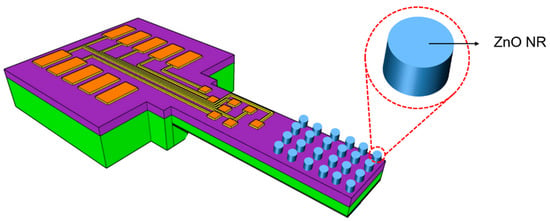
Figure 1.
Schematic of micro-electro-mechanical system (MEMS) silicon cantilever sensor functionalized with ZnO nanorods (NRs) on the top surface.
Phase-locked loop (PLL)-based systems have been broadly used to realize continuous real-time frequency tracking of resonant sensors [8,9,10], which principally employ the excitation frequency as a means to control the phase difference between excitation signal and sensor output. In the case of cantilever sensors, the phase difference in resonance is ideally independent of the resonant frequency. Therefore, the resonant frequency can be monitored by tracking the resonance phase. When the resonance phase has reached the desired phase difference, the output frequency of the PLL stays constant. This is commonly referred to as frequency lock and is interpreted as the resonant frequency in this work. Here, the resonance phase becomes an essential parameter for detecting the resonant frequency.
In this study, we implemented a PLL-based system for tracking the resonance shifting of an electro-thermal piezoresistive silicon cantilever resonator, which is subsequently called an electro-thermal piezoresistive cantilever sensor. This cantilever was covered by zinc oxide nanorod (ZnO NR) arrays that were modified with self-assembled monolayers of chitosan (see Figure 1). Nevertheless, PLL systems do not function properly in electro-thermal piezoresistive cantilever sensors due to their reversed phase response. Low thermal-mechanical coupling and parasitic direct thermal coupling [3] are inhibitive to an ideal phase response. Resonance tracking cannot work properly then, because there is an ambiguity in the phase response, which subsequently leads to instabilities during the locking process of the resonant frequency. Therefore, there is a need to develop a technique that can guarantee an utmost suppression of parasitic effects on electro-thermal piezoresistive cantilever sensors. Some work uses dual sensor systems that are fabricated in the same chip for cancelling the parasitic effects [11,12,13]. However, implementation of dual sensor systems will enlarge the sensor size and increase its power consumption. In the case of electro-thermal piezoresistive cantilever sensors, realizing the similar effect of direct thermal-parasitic coupling between two cantilevers is complicated as the heat supply and the boundary condition, which cause the temperature distribution in the cantilever body, are not easily controlled precisely. Therefore, hereby we apply an external reference signal in order to obtain a symmetric amplitude shape and a monotonic phase response by subtracting it from the outputs of the electro-thermal piezoresistive cantilever sensor [14]. By using an external circuit, the amplitude and phase of the reference signal can be controlled at a given frequency to obtain a suitable signal for eliminating the direct thermal-parasitic effect. We expect that the implementation of reference signal subtraction can expedite resonance tracking based on the PLL technique and reduce instabilities during the locking process of the resonant frequency. As proof-of-concept measurements, we investigated the resonance tracking of electro-thermal piezoresistive cantilever sensors under different levels of relative humidity (rH). MEMS cantilever sensors with ZnO NRs and a chitosan layer are highly sensitive to rH, and can most conveniently be used for sensing volatile organic compounds (VOCs) [15,16] and gases [17,18].
2. Self-Actuating and Self-Sensing
Electro-thermal piezoresistive cantilever sensors were fabricated using bulk silicon wafers and a bulk micromachining technique, leading to lower cost of materials and fabrication processes with respect to surface micromachining [19]. This cantilever sensor design comprises two main parts, i.e., for mechanical actuation and electrical sensing. Both are realized in the form of diffused p-type silicon resistors (Figure 2). A heating resistor (HR) and piezoresistors in a U-shaped full Wheatstone bridge (WB) configuration act as actuating and sensing components, respectively [20]. The HR, located at the cantilever clamped end, triggers an in-plane actuation of the cantilever beam. Subsequently, this deflection is sensed by the WB that is located about 33 µm away from the HR. The average size of the diffused resistors is around 60 µm × 10 µm. The cantilever beam has a total length of 1000 µm, a width of 170 µm, and a thickness of 12 µm. Details of the fabrication procedure of the electro-thermal piezoresistive cantilever sensors covered by ZnO NRs and chitosan layer were described previously in [2,21,22].
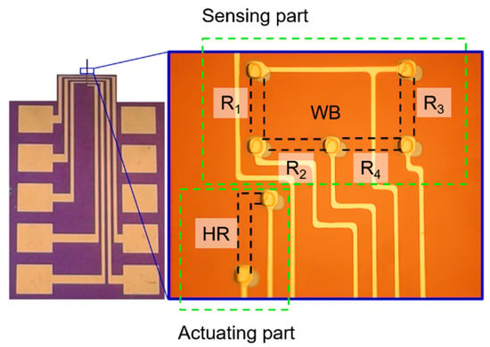
Figure 2.
Optical micrograph of the electro-thermal piezoresistive cantilever sensor top surface showing the heating resistor (HR, actuating part) and the U-shaped Wheatstone bridge (WB) with resistors Ri (i = 1,2,3,4) representing the sensing part.
Mechanical actuation is obtained by applying an alternating current (AC) voltage Vaccos(2πft) superimposed on a direct current (DC) voltage Vdc to the HR (Figure 3, in black line). The electrical current passing through the HR is converted into heat by the Joule heating effect. Consequently, the electrical power (P) is dissipated leading to a temperature field around the HR [9,23]. By inserting the AC and DC components into Equation (1), the resulting power loss (dissipation energy) P can be illustrated by a waveform, which is indicated by the red curve in Figure 3. In order to avoid an additional oscillation with double period in the red curve, the amplitude of the third summand on the right side of Equation (1) should be much higher than the fourth.
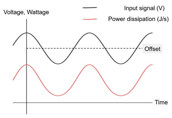
Figure 3.
Illustration of input voltage signal (AC + DC offset) of the HR (black line) that result in a power dissipation (red line) which is in-phase with the input signal.
Here, R is the resistance of the HR, Vdc and Vac are the DC and AC voltage amplitudes, respectively, f is the excitation frequency, and t is time.
Thermal energy is mostly generated due to the loss of kinetic energy of the current carrying electrons by collisions among themselves and with the lattice atoms [24]. The thermal energy subsequently results in static and dynamic temperature distributions in the cantilever. To further analyze the temperature distribution and the thermally induced deflection of the microcantilevers due to the Joule heating, finite element modelling (FEM) by COMSOL Multiphysics 4.4b was performed using a 5 V DC voltage at the input of the HR. FEM shows that there is a temperature gradient in the vicinity of the HR, with a maximum temperature of 302.4 K observed around the center of the HR (Figure 4a). This local temperature increase yields an expansion of the cantilever around the HR leading to a bending of the cantilever in the lateral (in-plane) direction. A total static displacement at the free end of approximately 17.8 nm is observed (Figure 4b).
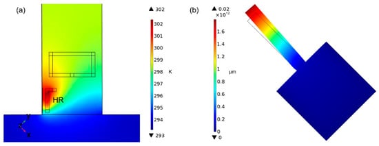
Figure 4.
Finite element modelling (FEM) simulations of (a) a heating resistor (HR) with resistance of 1000 Ω (p-silicon; lightly doped; specific heat capacity (Cp) = 700 J/(kg·K); coefficient of thermal expansion (α) = 2.6 × 10⁻⁶ K−1) and (b) beam deflection due to induced thermal-strain.
As discussed before, the response due to the electro-thermal actuation is sensed by four piezoresistors configured in a U-shaped WB. The WB was designed for adapting the strain distribution induced in the cantilever due to its lateral bending. Because of the dependence of resistivity on the applied strain ε, the resistors Ri (i = 1, …, 4) of the WB experiences relative resistance changes ΔRi according to:
where πl/t and σi are, respectively, the longitudinal/transverse piezoresistive coefficient of p-type silicon along the (110) crystal direction and the stress along the cantilever axis at the position of the resistor Ri. By applying a supply voltage (VWB_in) to the full WB circuit, the cantilever bending leads to an integral bridge resistance change ΔR, which can be recorded via the (transverse) output voltage (VWB_out) of the WB.
Basically, a WB is a parallel combination of two voltage dividers (shown in Figure 5), which subdivide a large voltage into smaller ones. The WB configuration can be used to measure very low values of resistances down to the milli-ohms range. This is done by detecting a voltage difference between the two output terminals (A and B). These two outputs are subsequently fed into an instrumentation amplifier (INA217) that detects their differences. In the case of a DC signal input (VA, VB), the amplifier subtracts and amplifies the input voltages according to Vout = G(VB − VA), where G is an amplification factor. Nevertheless, the WB on the cantilever generates VA and VB in the form of voltage oscillations. Therefore, in the differential amplifier output we obtain a sinusoidal signal having the same frequency as the actuation signal. Figure 6 shows the amplified output voltage in the time domain at resonance with an output signal to noise ratio (SNR) of 31.6 dB.
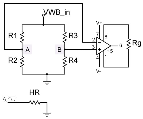
Figure 5.
Electronic circuit diagram of the U-shape Wheatstone bridge (WB) as the sensing part in our electro-thermal piezoresistive cantilever that is connected to an instrumentation amplifier.
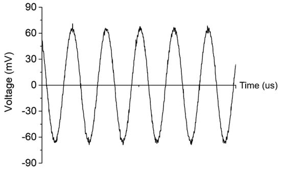
Figure 6.
A filtered output voltage after differential amplification of the WB output voltages VA and VB with a gain of 40 dB.
3. Reference Signal Subtraction
The amplified WB output signal (VWB_out) shows an asymmetric spectral amplitude line shape (Figure 7a) and a reversed phase response (Figure 7b) in the same frequency domain. An asymmetric amplitude shape that occurs concurrently with a reversed phase characteristic is called Fano resonance. It is yielded by mixing a discrete state (Lorentzian line shape) with a constant continuum background [25]. Therefore, in order to obtain a symmetric amplitude shape (Lorentzian line shape), elimination of the continuum background should be done by subtracting a corresponding characteristic. Simultaneously, the symmetric amplitude shape should then be accompanied by a monotonic phase response.
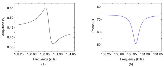
Figure 7.
(a) Asymmetric amplitude shape and (b) a reversed phase response of an electro-thermal piezoresistive cantilever sensor.
The setup of reference signal subtraction is shown in Figure 8. An AC signal (2 V) with offset voltage (5 VDC), generated by a lock-in amplifier (MFLI, Zurich Instruments, Zurich, Switzerland), actuates the cantilever through contact pad 2. The vibrations are then detected by the WB, which is supplied with 1 V DC through contact pad 6. Contact pads 1 and 5 act as common ground (GND). The voltage difference at the WB outputs, picked-up at contact pads 7 and 4, are then fed into the instrumentation amplifier through pin 2 and pin 3, respectively. Furthermore, the signal output of reference circuit was subtracted from the signal output of the instrument amplifier (pin 6). This subtraction was performed using both positive (V+) and negative (V−) voltage input terminals of the MFLI lock-in amplifier. The V+ and V− terminals were connected to the output signal of the instrumentation amplifier and the reference circuit, respectively, and the resultant output voltage (VO) was then calculated internally in the MFLI lock-in amplifier. The reference circuit was designed and fabricated to provide a controlling mechanism for the reference amplitude and phase signal through VR1 and VR2. It was intended to generate and provide a suitable characteristic reference signal, which could then be subtracted from signal of cantilever system. In order to yield a symmetric line shape at the differential output, the amplitude and phase of reference signal should be placed close to the baselines of the asymmetric amplitude and the reversed phase, respectively, of the electro-thermal piezoresistive cantilever.
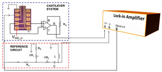
Figure 8.
Setup of phase-characteristic optimization by reference signal subtraction.
The signals of electro-thermal piezoresistive cantilever sensor and reference circuit, during measurement, are depicted in Figure 9. The sensor amplitude (Figure 9a, black full line) has a baseline between ~0.466 V and ~0.418 V whilst the baseline of the phase (Figure 9b, blue full line) ranges from ~73.60° to ~72.93° in the same frequency band, i.e., from 180.25 to 181.65 kHz. The reference signal was then adjusted to the baseline of the sensor signal by VR1 and VR2 (see Figure 8), which resulted in a measured reference amplitude increasing from ~0.436 V to ~0.441 V and a phase response decreasing from ~70.35° to ~ 70.12° in the examined frequency range (shown in red dash-dot line). The slight sloping behavior is caused by the inductance of the RCL circuit.
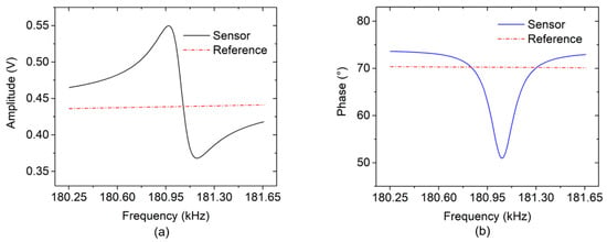
Figure 9.
Measured sensor and reference signals: (a) amplitude with asymmetric shape and (b) phase with a reversed characteristic both with nearly constant references.
Subtracting the reference from the sensor signal yields the required symmetric amplitude shape (Figure 10a, full line) and an extended frequency range of monotonic phase response (Figure 10b, dash-dot-dot line). The resonant frequency is measured at f0 = 181.052 kHz, the stop band rejection of amplitude response increases from 83 mV to 173 mV, while the phase response range increases from 21.82° to 75.61°.
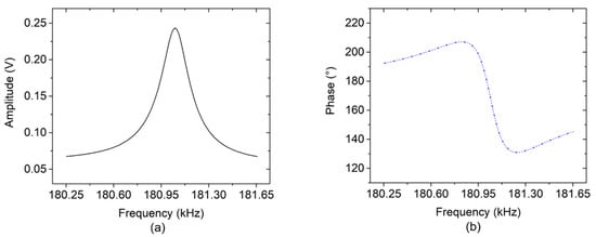
Figure 10.
Measured (a) amplitude and (b) phase responses of the electro-thermal piezoresistive cantilever including reference subtraction.
To evaluate the measured resonant frequency (obtained by the reference subtraction method), a Fano fitting approach [25] was used to extract the resonant frequency f0 and the quality factor Q of the asymmetric signal. The f0 and Q are the most relevant parameters of the resonant-mode line shape, which have a main influence on the sensitivity and detection limit of added substances on the cantilever. In the Fano fitting approach, the signal amplitude σ is modeled by Equation (3) to extract the resonant frequency f0, and Q is calculated using Equation (4).
where q, f, g, H are the asymmetry factor, the frequency, curve width, and gain parameters respectively. An offset σ0 and a term varying linearly with frequency (c × f) represent a frequency-dependent part of the baseline. In the calculation of Q, the term (c × f) is neglected, because it has only a small influence on the resonance line shape.
The measured asymmetric amplitude response (cf. black full line of Figure 9a) and the corresponding amplitude Fano fitting curve of an electro-thermal piezoresistive cantilever sensor are depicted in Figure 11. For fitting the curve, we implement a nonlinear least squares method with 95% confidence interval, thereby resulting in f0 ≈ 181.055 kHz and Q ≈ 936. By fitting the simple harmonic oscillator (SHO) formula to the data of Figure 10a, we obtain f0 = 181.052 kHz and Q = 858 from the measured differential resonance signal. The obtained results from the two approaches indicate that the resonant frequencies are comparable and similar. The observed lower Q-factor obtained from the measured differential resonance signal are caused by non-perfect reference signal.
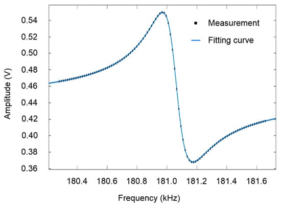
Figure 11.
Fano fitting of a measured resonance response with asymmetric amplitude line shape of an electro-thermal piezoresistive cantilever with ZnO NRs and chitosan self-assembled monolayers.
4. Real-Time Resonant Frequency Tracking
Tracking of the resonance frequency is performed by implementing the PLL technique, as shown in Figure 12. Applying sensor and reference signals at differential mode results in a symmetric amplitude shape (black full line) and an extended range of monotonic phase response with no ambiguity in the phase response (blue dash-dot-dot line), as depicted in Figure 13. The monotonic phase response is applicable in the PLL-based system for resonant frequency tracking. From the highest peak of amplitude, the resonance phase φ0, is determined. It is subsequently used as a set point of phase. In the PLL, this set-point value is subtracted from the measured phase difference (resulted from mixing process of differential output and oscillator), generating a current error signal e(t). A proportional controller (P-controller) results in an output that is proportional to e(t). The response time of the P-controller is adjusted by a proportional gain Kp which, however, never reaches the steady state condition and thus maintains the steady-state error. Due to this limitation, an integral controller (I) is used in addition to eliminate the steady-state error. It integrates the current error e(t) with the previous errors at every sampling time τ and then sums a cumulative error e(τ) over a certain time until it approaches zero. The controller speed can be increased by enlarging the integral gain Ki and the proportional gain Kp. Once the error signal is zero, the resonance frequency f0 is determined and can be tracked henceforth. These two PI parameters are set to achieve the highest precision possible, while still accurately tracking the resonant frequency.
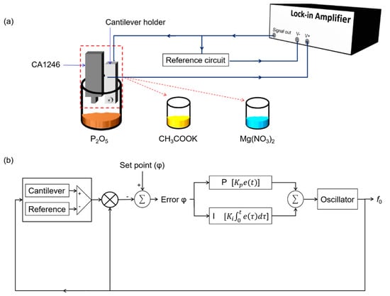
Figure 12.
(a) Measurement setup for real-time measurement of rH using an electro-thermal piezoresistive cantilever with ZnO NRs and chitosan self-assembled monolayers and a commercial thermohygrometer. (b) A block diagram of the reference-subtraction control system.
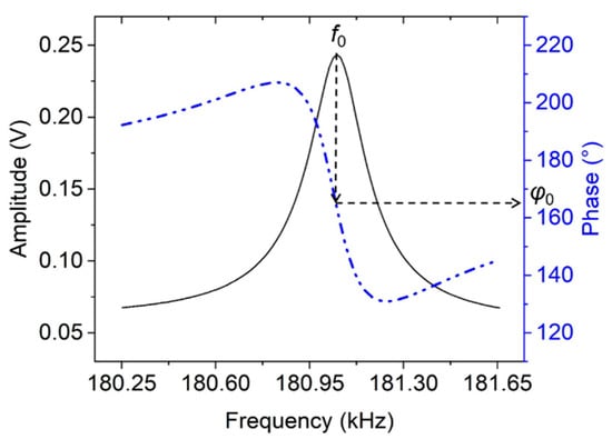
Figure 13.
Symmetric amplitude shape with extended range of monotonic phase response. The phase set point φ0 for the phase-locked loop (PLL) corresponds to the frequency f0 of the amplitude maximum.
The experiment setup shown in Figure 12 is used to confirm the performance of the monotonic phase response that is obtained by subtracting the reference signal from the sensor output. The resonant frequency tracking under changing relative humidity (rH) has been realized by using a lock-in amplifier with an integrated PLL system (MFLI, Zurich Instruments). For comparison, rH was simultaneously measured using a commercial thermohygrometer (CA 1246, Chauvin Arnoux, Paris, France). In these experiments, we investigated if the resultant nearly monotonic phase response would yield an improved response during the resonance frequency tracking. Therefore, the test configuration involved an assessment of the resonance response and rH using both the electro-thermal piezoresistive cantilever sensor (coated with ZnO NRs and chitosan) and the commercial rH sensor under identical conditions. Both sensors were simultaneously placed in a bottle filled with a chemical solution that defined a certain rH level. Different chemical solutions were used, including phosphor pentoxide (P2O5), potassium acetate (CH3COOK), and magnesium nitrate (Mg(NO3)2). The sensors measured rH (thermohygrometer) and the corresponding frequency shift (cantilever sensor) in the bottle over time, and were then removed and stabilized at ambient air before sequentially transferring them to another bottle-filled chemical solution.
The experimental results (Figure 14) showed the resonant frequency shifts (cantilever sensor) and relative humidity (thermohygrometer, commercial sensor) over time. The rH levels measured by the thermohygrometer were 19.37 ± 0.77%, 37.88 ± 0.70%, and 50.68 ± 0.97% for P2O5, CH3COOK, and Mg(NO3)2, respectively. In the P2O5 and CH3COOK solutions, the electro-thermal piezoresistive cantilever sensor presents large frequency changes Δf0, i.e., ~268.8 Hz (region B–C) and ~99.9 Hz (region D–E). Moreover, this cantilever sensor also stabilizes faster than the commercial sensor at ambient conditions as shown in regions of C–D and G–H. Obviously, the ZnO NRs and chitosan on the cantilever more directly interact with the ambient air by absorbing and desorbing of water molecules thereby yielding a fast response during changes of ambient conditions compared with the commercial sensor, which uses capacitive-based sensing technique. In this case, the water molecules should first pass through the conductor plate before reaching the dielectric material, which then modifies its capacitance value. Therefore, it takes some time to stabilize during the absorption phase for every rH level. From here, we can conclude that the electro-thermal piezoresistive cantilever sensor with ZnO NRs and chitosan layer shows a better response time during the absorption process compared to the commercial rH sensor.
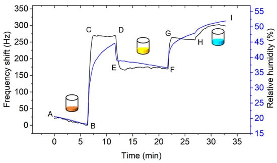
Figure 14.
Time-dependent resonant frequency shift (Δf0) and rH measurements using an electro-thermal piezoresistive cantilever sensor and a thermohygrometer, respectively, between ambient conditions (rH of ~44–48%) and defined rH levels P2O5 (brown); CH3COOK (yellow) and Mg(NO3)2 (blue).
At higher rH level, i.e., Mg(NO3)2 solution, however, the electro-thermal piezoresistive cantilever sensor exhibits a slower response time (see Figure 14 (region H–I)) compared to P2O5 and CH3COOK solutions. This is supposedly caused by a non-ideal configuration between the sensor and reference signals at higher concentration of the water molecules. This condition is expected due to the change of the baselines of the amplitude and phase responses of the sensor output. Moreover, the Q-factor changes with rH level as well. By applying a fitting curve method on the sensor amplitude responses, Q-values of about 1893 and 1779 were respectively obtained at low (Figure 15a, 1st condition) and high (Figure 15b, 2nd condition) rH levels. This is an improvement compared to the previously reported Q-values for a ZnO-covered cantilever at different rH levels, in which it was observed to decrease from 514 ± 18 (rH = 30%) to 437 ± 15 (rH = 60%) [26].
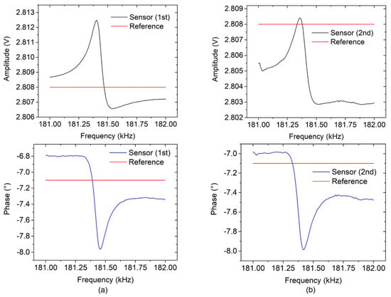
Figure 15.
(a) Ideal configuration between sensor and reference signals for optimizing its phase response, while in (b) it is not ideal. For both operating conditions, the same reference signal is used.
The illustrations in Figure 15 explain how a non-ideal configuration between sensor and reference signals can gradually occur after extended operation and a corresponding increase of added mass on the electro-thermal piezoresistive cantilever sensor. At the beginning (1st condition), we have an ideal configuration as shown in Figure 15a, i.e., the reference signals (red) are put in balanced positions between the baselines of amplitude and phase, respectively, of the sensor signal. In the 2nd condition, the mass added to the cantilever had increased. In this case, we have a non-ideal configuration of sensor and reference signals. Amplitude and phase values shifted downwards to the reference signal as shown in Figure 15b. This condition is expected to reduce the symmetry of amplitude line shape and to thus yield a reversed phase response again. As previously explained, a reversed phase response leads to signal instability in resonance locking. Development of an adaptive reference signal is therefore required to ensure a monotonic phase response during real-time measurement and to overcome this issue.
5. Conclusions
Asymmetric resonance in electro-thermal piezoresistive cantilever sensors with ZnO NRs and chitosan has been successfully suppressed by subtracting a reference signal from the sensor output. This technique reveals that monotonic phase responses are suitable for implementation in a PLL system for tracking the resonant frequency of the sensor. By subtraction of a reference, symmetric amplitude shapes can be effectively obtained from measured asymmetric resonance signals. Nearly monotonic phase responses achieved by this technique have been employed successfully in a PLL system, resulting in effective frequency tracking under changing rH conditions. However, further investigation is still necessary to implement reference signals under a wide range of conditions (e.g., in sensor assessments towards exposure to chemical analytes) due to changing Q-factor of the sensor during measurement. Moreover, an adaptive reference will become a further challenge to be undertaken.
Author Contributions
A.S., as the first author, planned and manufactured important parts of the setup, planned and performed the experiments, carried out the data evaluation and drafted the manuscript. J.X. participated in fabricating the sensor and contributed in the building of the experimental setup for relative humidity. M.F. contributed in reviewing and discussing the fundamental electronic principles and setups related in this study. M.B. provided fundamental ideas for the Fano-fitting approach used in this work. W.O.N. discussed the experimental results and contributed to the manuscript. H.S.W. and E.P. provided invaluable guidance and recommendations in improving work and manuscript.
Funding
This project has received funding from the EMPIR programme co-financed by the Participating States and from the European Union’s Horizon 2020 research and innovation programme under no. 17IND05 MicroProbes.
Acknowledgments
A. Setiono would like to thank the Ministry of Research, Technology and Higher Education of the Republic of Indonesia (RISTEKDIKTI) for the Ph.D. scholarship of RISET-Pro under no. 343/RISET-Pro/FGS/VIII/2016 (World Bank Loan No. 8245-ID) and Indonesian-German Center for Nano and Quantum Technologies (IG-Nano) for the support. J. Xu, M. Bertke, and W. O. Nyang‘au are grateful for funding from the China Scholarship Council (CSC) under the Grant CSC No. 201506300019, from “Niedersächsisches Vorab”, Germany, through the “Quantum- and Nanometrology (QUANOMET)” initiative within the project of “NP 2-2”, and from the German Federal Ministry for Economic Cooperation and Development (BMZ) within the Braunschweig International Graduate School of Metrology, respectively. H.S. Wasisto acknowledges the Lower Saxony Ministry for Science and Culture (N-MWK) for funding of LENA-OptoSense group. We are also grateful to Angelika Schmidt, Aileen Michalski, Karl-Heinz Lachmund, Zhenshuo Ding, Xuejing Li, and Ratna Indrawijaya, M.Sc. for their assistance during preparation of research tools as well as many fruitful discussions.
Conflicts of Interest
The authors declare that they have no conflict of interest.
References
- Nathawat, R.; Patel, M.; Ray, P.; Gilda, N.A.; Vinchurkar, M.S.; Rao, V.R. ZnO nanorods based ultra sensitive and selective explosive sensor. In Proceedings of the 2013 IEEE International Nanoelectronics Conference (INEC), Singapore, 2–4 January 2013; pp. 40–42. [Google Scholar]
- Xu, J.; Bertke, M.; Li, X.; Mu, H.; Zhou, H.; Yu, F.; Hamdana, G.; Schmidt, A.; Bremers, H.; Peiner, E. Fabrication of ZnO nanorods and Chitosan@ZnO nanorods on MEMS piezoresistive self-actuating silicon microcantilever for humidity sensing. Sens. Actuators B Chem. 2018, 273, 276–287. [Google Scholar] [CrossRef]
- Schlur, L.; Hofer, M.; Ahmad, A.; Bonnot, K.; Holz, M.; Spitzer, D. Cu(OH)2 and CuO Nanorod Synthesis on Piezoresistive Cantilevers for the Selective Detection of Nitrogen Dioxide. Sensors 2018, 18, 1108. [Google Scholar] [CrossRef] [PubMed]
- Wasisto, H.S.; Steib, F.; Merzsch, S.; Waag, A.; Peiner, E. Vertical silicon nanowire array-patterned microcantilever resonators for enhanced detection of cigarette smoke aerosols. Micro Nano Lett. 2014, 9, 676–679. [Google Scholar] [CrossRef]
- Bertke, M.; Fahrbach, M.; Hamdana, G.; Xu, J.; Wasisto, H.S.; Peiner, E. Contact resonance spectroscopy for on-the-machine manufactory monitoring. Sens. Actuators A Phys. 2018, 279, 501–508. [Google Scholar] [CrossRef]
- Thuau, D.; Ayela, C.; Lemaire, E.; Heinrich, S.; Poulin, P.; Dufour, I. Advanced thermo-mechanical characterization of organic materials by piezoresistive organic resonators. Mater. Horiz. 2015, 2, 106–112. [Google Scholar] [CrossRef]
- Thuau, D.; Ducrot, P.-H.; Poulin, P.; Dufour, I.; Ayela, C. Integrated Electromechanical Transduction Schemes for Polymer MEMS Sensors. Micromachines 2018, 9, 197. [Google Scholar] [CrossRef] [PubMed]
- Wasisto, H.S.; Zhang, Q.; Merzsch, S.; Waag, A.; Peiner, E. A phase-locked loop frequency tracking system for portable microelectromechanical piezoresistive cantilever mass sensors. Microsyst. Technol. 2014, 20, 559–569. [Google Scholar] [CrossRef]
- Wasisto, H.S.; Merzsch, S.; Uhde, E.; Waag, A.; Peiner, E. Handheld personal airborne nanoparticle detector based on microelectromechanical silicon resonant cantilever. Microelectron. Eng. 2015, 145, 96–103. [Google Scholar] [CrossRef]
- Toledo, J.; Jiménez-Márquez, F.; Úbeda, J.; Ruiz-Díez, V.; Pfusterschmied, G.; Schmid, U.; Sánchez-Rojas, J.L. Piezoelectric MEMS resonators for monitoring grape must fermentation. J. Phys. Conf. Ser. 2016, 757, 12020. [Google Scholar] [CrossRef]
- Chu, C.-C.; Dey, S.; Liu, T.-Y.; Chen, C.-C.; Li, S.-S. Thermal-Piezoresistive SOI-MEMS Oscillators Based on a Fully Differential Mechanically Coupled Resonator Array for Mass Sensing Applications. J. Microelectromech. Syst. 2018, 27, 59–72. [Google Scholar] [CrossRef]
- Kangul, M.; Aydin, E.; Gokce, F.; Zorlu, O.; Kulah, H. Analysis and Elimination of the Capacitive Feedthrough Current on Electrostatically Actuated and Sensed Resonance-Based MEMS Sensors. J. Microelectromech. Syst. 2017, 26, 1272–1278. [Google Scholar] [CrossRef]
- Toledo, J.; Manzaneque, T.; Ruiz-Díez, V.; Jiménez-Márquez, F.; Kucera, M.; Pfusterschmied, G.; Wistrela, E.; Schmid, U.; Sánchez-Rojas, J.L. Comparison of in-plane and out-of-plane piezoelectric microresonators for real-time monitoring of engine oil contamination with diesel. Microsyst. Technol. 2016, 22, 1781–1790. [Google Scholar] [CrossRef]
- Setiono, A.; Fahrbach, M.; Bertke, M.; Xu, J.; Hamdana, G.; Wasisto, H.S.; Peiner, E. Phase characteristic optimization of resonant MEMS environmental sensors. In Proceedings of the 19th ITG/GMA Symposium, Nuremberg, Germany, 26–27 June 2018. [Google Scholar]
- Lee, K.; Baek, D.-H.; Kim, J. Fabrication and characterization of VOC sensors based on suspended zinc oxide nanorods functionalized by cobalt porphyrin. In Proceedings of the 2017 19th International Conference on Solid-State Sensors, Actuators and Microsystems (TRANSDUCERS), Kaohsiung, Taiwan, 18–22 June 2017; pp. 307–310. [Google Scholar]
- Vessalli, B.A.; Zito, C.A.; Perfecto, T.M.; Volanti, D.P.; Mazon, T. ZnO nanorods/graphene oxide sheets prepared by chemical bath deposition for volatile organic compounds detection. J. Alloys Compd. 2017, 696, 996–1003. [Google Scholar] [CrossRef]
- Leonardi, S. Two-Dimensional Zinc Oxide Nanostructures for Gas Sensor Applications. Chemosensors 2017, 5, 17. [Google Scholar] [CrossRef]
- Galstyan, V.; Comini, E.; Ponzoni, A.; Sberveglieri, V.; Sberveglieri, G. ZnO Quasi-1D Nanostructures: Synthesis, Modeling, and Properties for Applications in Conductometric Chemical Sensors. Chemosensors 2016, 4, 6. [Google Scholar] [CrossRef]
- Bertke, M.; Hamdana, G.; Wu, W.; Marks, M.; Wasisto, H.S.; Peiner, E. Asymmetric resonance frequency analysis of in-plane electrothermal silicon cantilevers for nanoparticle sensors. J. Phys. Conf. Ser. 2016, 757, 12006. [Google Scholar] [CrossRef]
- Beardslee, L.A.; Addous, A.M.; Heinrich, S.; Josse, F.; Dufour, I.; Brand, O. Thermal Excitation and Piezoresistive Detection of Cantilever In-Plane Resonance Modes for Sensing Applications. J. Microelectromech. Syst. 2010, 19, 1015–1017. [Google Scholar] [CrossRef]
- Xu, J.; Bertke, M.; Gad, A.; Yu, F.; Hamdana, G.; Bakin, A.; Peiner, E. Fabrication of ZnO Nanorods on MEMS Piezoresistive Silicon Microcantilevers for Environmental Monitoring. Proceedings 2017, 1, 290. [Google Scholar] [CrossRef]
- Xu, J.; Bertke, M.; Li, X.; Mu, H.; Yu, F.; Schmidt, A.; Bakin, A.; Peiner, E. Self-actuating and self-sensing ZNO nanorods/chitosan coated piezoresistive silicon microcantilever for humidit Y sensing. In Proceedings of the 2018 IEEE Micro Electro Mechanical Systems (MEMS), Belfast, UK, 21–25 January 2018; pp. 206–209. [Google Scholar]
- Brand, O.; Dufour, I.; Heinrich, S.M.; Josse, F. Resonant MEMS. Fundamentals, Implementation and Application; Brand, O., Dufour, I., Heinrich, S.M., Josse, F., Eds.; Wiley-VCH: Weinheim, Germany, 2015. [Google Scholar]
- Ansari, M.Z.; Cho, C. An analytical model of joule heating in piezoresistive microcantilevers. Sensors 2010, 10, 9668–9686. [Google Scholar] [CrossRef]
- Bertke, M.; Hamdana, G.; Wu, W.; Wasisto, H.S.; Uhde, E.; Peiner, E. Analysis of asymmetric resonance response of thermally excited silicon micro-cantilevers for mass-sensitive nanoparticle detection. J. Micromech. Microeng. 2017, 27, 64001. [Google Scholar] [CrossRef]
- Yang, J.; Xu, J.; Wu, W.; Bertke, M.; Wasisto, H.S.; Peiner, E. Piezoresistive Silicon Cantilever Covered by ZnO Nanorods for Humidity Sensing. Procedia Eng. 2016, 168, 1114–1117. [Google Scholar] [CrossRef]
© 2019 by the authors. Licensee MDPI, Basel, Switzerland. This article is an open access article distributed under the terms and conditions of the Creative Commons Attribution (CC BY) license (http://creativecommons.org/licenses/by/4.0/).