Article

Label-Free Biosensing Method for the Detection of a Pancreatic Cancer Biomarker Based on Dielectrophoresis Spectroscopy

by
Fleming Dackson Gudagunti
,
Logeeshan Velmanickam
,
Dharmakeerthi Nawarathna
and
Ivan T. Lima, Jr.
*
Department of Electrical and Computer Engineering, North Dakota State University, Fargo, ND 58108-6050, USA
*
Author to whom correspondence should be addressed.
Chemosensors 2018, 6(3), 33; https://doi.org/10.3390/chemosensors6030033
Submission received: 9 July 2018 / Revised: 7 August 2018 / Accepted: 7 August 2018 / Published: 11 August 2018
(This article belongs to the Special Issue Label-Free Biosensors and Chemical Sensors)

Abstract

:
We show that negative dielectrophoresis (DEP) spectroscopy is an effective transduction mechanism of a biosensor for the diagnosis and prognosis of pancreatic cancer using the biomarker CA 19-9. A substantial change in the negative DEP force applied to functionalized polystyrene microspheres (PM) was observed with respect to both the concentration level of the pancreatic cancer biomarker CA 19-9 and the frequency of the electric field produced by a pearl shaped interdigitated gold micro-electrode. The velocity of repulsion of a set of PM functionalized to a monoclonal antibody to CA 19-9 was calculated for several concentration cutoff levels of CA 19-9, including 0 U/mL and 37 U/mL, at the frequency range from 0.5 to 2 MHz. The velocity of repulsion of the PM from the electrode was determined using a side illumination and an automated software using a real-time image processing technique that captures the Mie scattering from the PM. Since negative DEP spectroscopy is an effective transduction mechanism for the detection of the cutoff levels of CA 19-9, it has the potential to be used in the early stage diagnosis and in the prognosis of pancreatic cancer.

1. Introduction

Pancreatic cancer is one of the most fatal forms of cancer malignancies in humans. Surgical procedure remains the only remedial action for this distressing ailment [1]. The average five-year survival rate is 6% with less than one year of average survival time for the patients in the metastasis condition [1,2]. Hence it is vital to diagnose this condition at its early stage. The fluctuations of the levels of biochemical molecular biomarkers can be nucleic acids, peptides, carbohydrates, or proteins [3]. Carbohydrate antigen CA 19-9 is a pancreatic cancer biomarker [4] that received the approval by the U.S. Food and Drug Administration (FDA) for the monitoring of pancreatic cancer [5,6,7]. A detailed literature review of pancreatic cancer was conducted by [8] and they demonstrated various cutoff levels of CA 19-9 used as a screening tool in asymptomatic patients for the Diagnosis of Pancreatic Cancer. The predictive value of CA 19-9 in the diagnosis of pancreatic cancer rises with its increase in level. Steinberg et al. [9] showed that the percentage of pancreatic cancer incidence level is 72% with CA 19-9 over 37 U/mL. However, when the concentration of CA 19-9 exceeds 1000 U/mL, the probability of incidence of pancreatic cancer rises to more than 97%.
Several techniques have been proposed to detect CA 19-9. Most of the investigative procedures involve CA 19-9 monoclonal antibody 1116-NS-19-9 in recognizing CA 19-9 as an explicit probe [10,11,12]. Passerini et al. were the first group to develop a solid-phase radio immunometric sandwich assay that can readily react with a carbohydrate antigenic determinant CA 19-9 at low concentrations [11]. This has led to the development of enzyme-linked immunosorbent assay based techniques using electrochemical assays, photo-electrochemical assays, and fluorescent based assays [13]. Recent advances have detected CA 19-9 using Raman spectroscopy and surface plasmon resonance [14]. These techniques have drawbacks due to complicated and time-consuming protocols, thus requiring the presence of an expert to handle complex and expensive pieces of equipment. Moreover, in a previous study, we demonstrated that the method that we proposed based on negative DEP has high sensitivity that enables detection of as little as 80 molecules, which corresponds to 13 attomolars, per PM combined with the high specificity of an immunoassay with monoclonal antibodies [15,16]. DEP is a force produced by an electric field gradient in dielectric particles [17,18,19,20,21]. Negative DEP is a force produced by an electric field gradient to dielectric particles that is opposite to the direction of the electric field gradient. In this paper, we present a proof of principle of the use of negative dielectrophoresis (DEP) spectroscopy as the transduction mechanism to measure the concentration of CA 19-9 [22].

2. DEP Theory

Exposing a polarizable particle to an electric field will induce electrical charges on the particle. These induced electrical charges will then act upon the dipole to align them parallel to the applied electric field. If this electric field is non-uniform, a net force will be imposed due to uneven Coulomb forces acting upon the dipole. Based on particle’s polarizability in comparison with that of the suspending medium, the particle can move towards or off the region of applied electric field. This motion is called DEP [20,23].
The DEP force has the capability to selectively segregate, concentrate, or refine target molecules or particles from a complex sample by either attracting them to or repelling them from the electrodes. The translational forces produced due to attraction or repulsion are due to the interactions of the dipole moment of the particles with the applied non-uniform electric field [20].
The time averaged DEP force on a spherical particle of radius r is given by
F D E P = 2 π ε m r 3 R e [ K CM ( ω ) ] E 2 ,
where
K CM ( ω ) = ε p * ε m * ε p * + 2 ε m *
is the Clausius–Mossotti factor, which is the effective polarizability per unit volume of the particle, ε m is the permittivity of the medium, ε m * is the complex permittivity of the medium, ε p * is the complex permittivity of the particle, ∇E is the electric field gradient. Depending on the relative values of the complex permittivity of the particle and of the medium, the value of K CM ( ω ) varies from −0.5 to 1. If K CM ( ω ) is positive, the particles are attracted to regions of high electric field intensity: Positive DEP. Similarly, if K CM ( ω ) is negative, the particles are repelled from the regions of high electric field intensity: Negative DEP. Kawabata & Washizu exploited the dependence of the DEP force on molecular binding on the surface of functionalized PM to separate PM as a function of the molecular binding for alpha-fetoprotein and DNA strands [24]. DEP was also used to concentrate DNA molecules with [25] and without [26] PM.

3. Materials and Methods

3.1. DEP Spectroscopy Application

We developed a software application using Microsoft foundation classes in visual C++ for Windows that measures the drift velocity of dielectric particles due to DEP as a function of the frequency of the electric field applied to the interdigitated electrode. The application is integrated with USB video class (UVC) standard compliant microscope camera, Tektronix AFG series function generators, pearl-shaped interdigitated electrode, OMFL600 low power microscope, and a custom based optical side illumination technique. The developed application can capture a sequence of video frames from any USB video class standard compliant microscope camera. Using the acquired images, our system performs real time image processing to extract the effect of DEP force on the dielectric particles and, thus, the DEP spectrum can be obtained. A frame rate of 25 frames per second is used in the application for capturing and displaying the live video from the microscope camera. The dialog window that depicts the field of view being processed is as shown in Figure 1.
The application extracts information from the pixels, including the color, that is used by the real-time image processing algorithm. Since the purpose of this system is to monitor the effect of the DEP force on the suspended particles in the solution, the system monitors the regions of interest in the video where strong DEP effect is observed. The regions of interest are the areas in which the electric field gradient and, consequently, the DEP force is the strongest. The regions of interest include the rectangles shown in Figure 1, which form the areas in the field of view of the camera that are processed to calculate the drift velocity due to the DEP force as a function of the frequency of the electric field. The drift velocity is proportional to the friction force and, consequently, is proportional to the DEP force. A desired time interval is set to capture time lapse images for the drift velocity calculation. The minimum time interval to capture an image or to record a new data value is in the order of 40 ms, which is determined by the frame rate of the video stream and processing speed of the hardware.

3.2. Sampe Preparation

The sample preparation consists of the following steps:
Step 1: Streptavidin attachment to biotinylated PM. Biotinylated PM with 750 nm diameter were purchased from Spherotech Inc. The first step in the preparation of samples consists of binding the biotinylated PM with the antigen Streptavidin purchased from Vector Labs Inc. Biotin acts as a conjugate to the protein Streptavidin and forms a strong bond with very high affinity. This process is done first by adding a 3 μL Streptavidin solution into a 10 μL biotinylated PM solution in a centrifuge tube to have a 100% binding, according to the manufacturer recommendation. The total volume was set to 400 μL by adding 0.01× phosphate-buffered saline (PBS) solution with conductivity 0.01 S/m. Then, the sample was uniformly mixed using a vortex machine and left on a shaker for 20 min for the Streptavidin–biotin binding process. After 20 min, the tube was centrifuged at 5000 rpm for 14 min to remove the unbound Streptavidin molecules and the buffer.
Step 2: Biotinylated CA 19-9 antibody attachment to the biotinylated PM + Streptavidin. Each Streptavidin molecule can bind up to 4 biotin molecules. One binding site of each Streptavidin molecule is used to bind that Streptavidin molecule with the PM. The remaining three Streptavidin binding sites bind with three biotinylated CA 19-9 antibodies. First, 3 μL of biotinylated CA 19-9 antibody was added in to 397 μL of 0.01× PBS to have 100% binding of the biotinylated antibodies with all the Streptavidin molecule binding sites, according to the manufacturer requirement. Then this sample was added in to the solution with Streptavidin–biotin PM and uniformly mixed using a vortex machine. After that, the sample was kept on a shaker for 20 min for the biotinylated CA 19-9 antibodies to bind with the Streptavidin molecules of the PM. After 20 min, the tube was centrifuged at 5000 rpm for 14 min to remove the unbound biotinylated CA 19-9 antibody molecules and the buffer.
Step 3: CA 19-9 Antigen attachment to the PM + Streptavidin + CA 19-9 antibody.
For this process, different concentration of CA 19-9 Antigen, including 18 U/mL and 37 U/mL, were prepared in a total volume of 400 μL 0.01× PBS buffer. Then, this sample was added to the centrifuged CA 19-9 antibody-bound PM and mixed uniformly using a vortex machine. After that, the sample was kept on a shaker for 30 min and the sample was centrifuged at 5000 rpm for 14 min to remove the unbound CA 19-9 antigen molecules and the buffer. Finally, 200 μL of 0.01× PBS buffer was added to the centrifuge tube and mixed uniformly.
A schematic representation of the three steps used in the sample preparation is shown in Figure 2.

3.3. Pearl-Shaped Interdigitated Electrode

In the experiments, we used a pearl-shaped interdigitated electrode that was designed and fabricated at North Dakota State University [27]. The electrode was designed and drawn to scale in AutoCAD, validated in COMSOL Multiphysics and fabricated on commercially available glass wafer using photolithography, metal sputtering and lift-off procedures using 1000 Å thick gold film in the microfabrication facilities at North Dakota State University. Our electrode can generate maximum electric field of 1.8 × 10⁴ V/m and gradients as high as 3 × 10¹² V2/m2, which is sufficient to produce strong DEP forces to dielectric particles with a few hundred nanometers of diameter. It was observed that the root mean square of the electric field and the electric field gradient produced by this electrode do not vary with the frequency from tens of kHz to several MHz. This ensures the sample is subjected to the same electric field gradient in all frequencies of interest, which makes DEP behavior depend only on the value of real part of the Clausius–Mossotti factor [28].

3.4. Illumination Setup

An interdigitated electrode, an OMFL600 low power microscope, a Tektronix AFG series function generator, and a custom-built green LED lamp illuminating with 45° of incidence were used in the experiment. This angle of incidence reduces the amount of light collected by the camera that does not result from light scattering from the PM, which is an implementation of dark field microscopy. When 10 µL of the assay was pipetted on the surface the electrode, a portion of the light scattered from the antigen bound PM is collected by the objective of the microscope, resulting in a sharp image of the antigen-bound PM. Since the diameter of the antigen bound PM is of the same order as the wavelength of the green LED (565 nm), the antigen bound PM appear bright on a dark background due to Mie scattering. Therefore, this is a label-free method, since no fluorescence markers to the target molecules need to be used for the transduction and, consequently, there is no need for a washing procedure to remove the unbound fluorescent markers.

3.5. Frequency Sweep and Image Processing

Before the drift velocity due to the DEP force can be measured for any frequency, positive DEP force needs to be applied to attract the PM to the edges of the electrode. Then, negative DEP is applied for a frequency in the frequency range of the spectrum used in the experiment. The software sets the function generator to scan through a set of electrical frequencies. For the experiments that we present here, the lowest frequency was set to 500 kHz, the frequency step was set to 300 kHz, and the highest frequency was 2 MHz for negative DEP. The peak-to-peak voltage value was set to10 V.
The time interval for positive DEP was set to 2000 ms and time interval for negative DEP was set to 80 ms per frequency measurement. The choice of these time intervals was determined after conducting a series of preliminary experiments. In case of positive DEP, the experiment starts with a certain start frequency fpDEP that induces positive DEP effect for the specified time interval to collect the PM to a region near the electrode. Then, the frequency is automatically changed to the frequency fnDEP,1 that induces negative DEP effect for the specified time interval and two images are obtained to measure the center of mass of the PM as they are being repelled from the electrode. Then, the cycle repeats with the waveform generator changing the frequency back to fpDEP to attract the PM to a region near the electrode. After that, the frequency is switched to the next frequency that produces negative DEP fnDEP,2. This cycle goes on until fnDEP reaches the stop frequency. The frequency switching by the function generator is done automatically by our application. Our application is designed for Tektronix AFG series function generators. The function generator is connected to the computer via USB port. We modified an Interchangeable Virtual Instruments Foundation (IVI) compliant device driver from LabWindows™/CVI environment to Microsoft Visual C++. This modified device driver along with TekVISA (Virtual Instrument Software Architecture) connectivity software was used to access and control the function generator from Microsoft Visual C++ program.
The spectrum measurement could also have been designed to measure the drift velocity due to positive DEP as a function of the frequency. However, positive DEP has a narrower frequency range for the dielectric particles that we are using. Moreover, it was easier to automate the measurement of the drift velocity due to negative DEP because the dielectric particles start drifting from the same region near the edge of the electrode at the onset of negative DEP.

4. Results

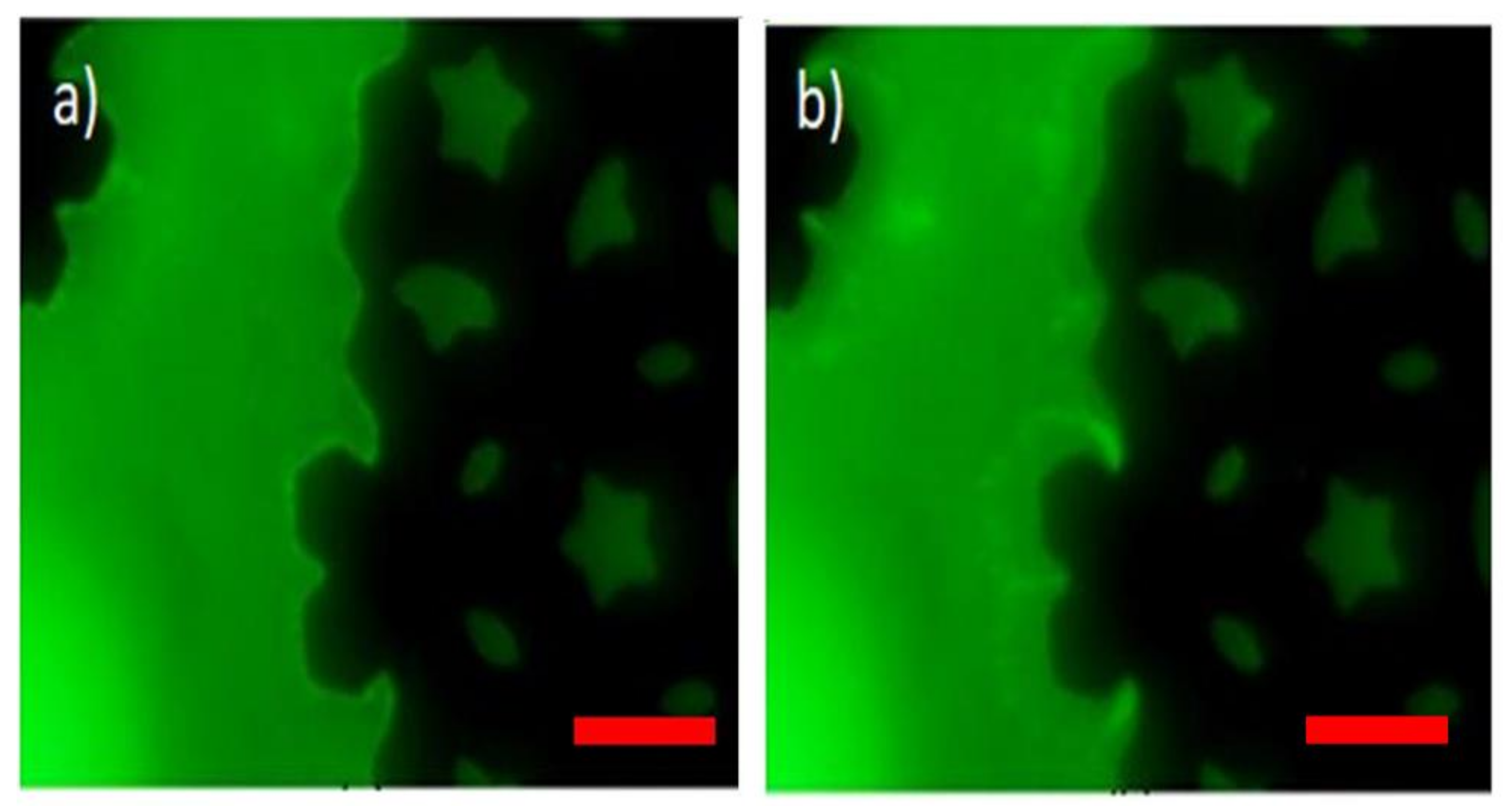
We validated our sensing method by carrying out DEP spectroscopy experiments with our image-processing software for observation and recording of the results during the experiments. The validation of the method is shown in Figure 3. Initially, the software automatically sets the function generator to the frequency 10 kHz to establish positive DEP. Low frequency electric fields (<50 kHz) produce positive DEP whereas high frequency electric fields (>250 kHz) produce negative DEP force to the PM that we use in this study. The positive DEP force results in the attraction of the PM towards the edge of the electrode. A clear PM layer can be seen forming at the edge of the electrode in Figure 3a. Once the PM form a layer at the edge of the electrode, our software automatically switches the frequency to a preset frequency that produces negative DEP. The negative DEP force pushes the PM from the edge of the electrode. The repulsion of the PM by the electrode is tracked and recorded using our custom-made software. Using this system, we calculated the drift velocity of the PM layer repulsed from the electrode, which is proportional to the DEP force, as they move away from the electrode edge using image processing.
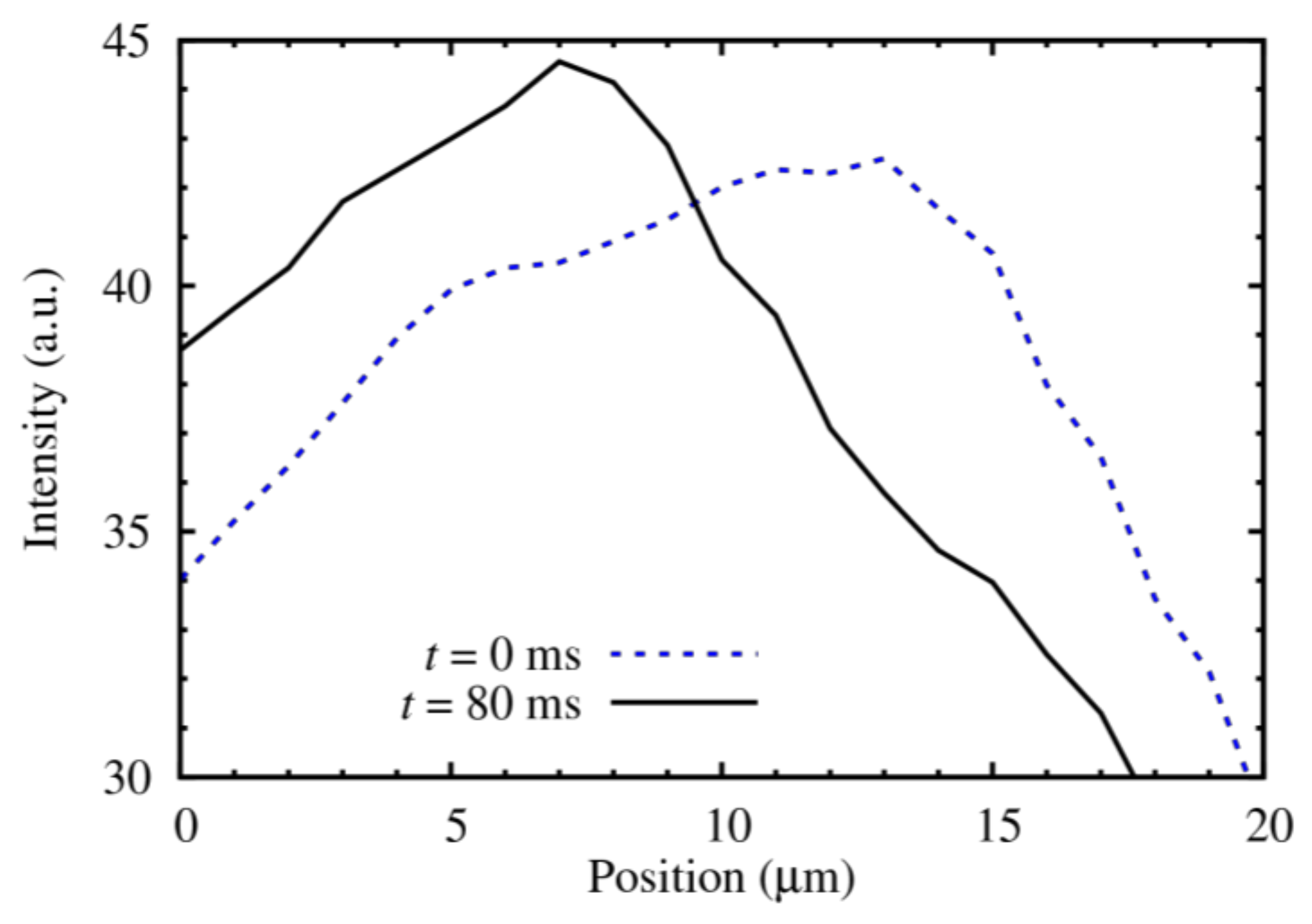
The system tracks the variation of the light intensity along the major axis of the box enclosing the region of interest, which is shown in Figure 1, at different time intervals, as shown in Figure 4 for 37 U/mL in 10 µL. The center of mass of the light intensity observed in the image corresponds to the average location of the PM. We process two images to calculate the speed of repulsion: The first image is captured shortly after negative DEP is applied and the second image is capture 80 ms later. The center of the mass of the light intensity is calculated for both images and is used to calculate the speed of the repulsion due to negative DEP.
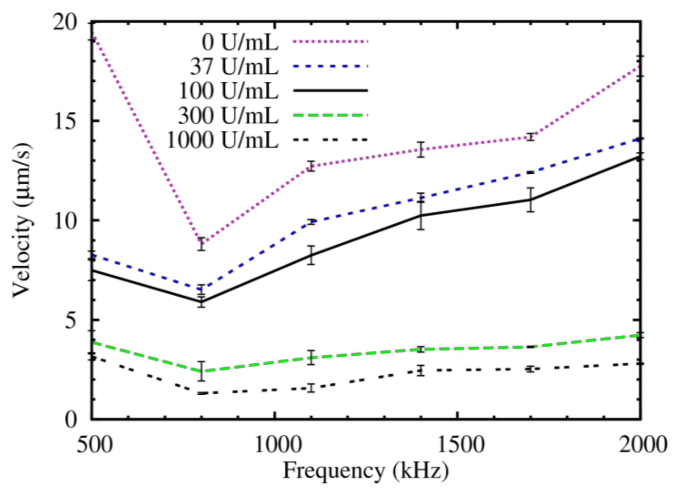
We observed a relationship between the speed of repulsion of the PM functionalized with CA 19-9 antibody as a function of both the frequency and the concentrations of the target CA 19-9 that we considered. As we switched to higher frequency electric fields from our software, we observed a clear dependence of the negative DEP spectrum on the concentration of the target CA 19-9 in the sample. While switching the frequency, we maintained all other experiment parameters and conditions constant. The obtained DEP spectroscopy results are shown in Figure 5. In this figure, we show the drift velocity of the center of mass of the PM layer as a function of the frequency for a single measurement. We also show error bars with the standard deviation obtained in six measurements, which is an indication of the confidence interval in each individual measurement. Since there is very little overlap between the confidence intervals of these curves, only one measurement of the DEP spectrum is needed in each experiment to accurately determine the cutoff level of CA 19-9. These results indicate that this label-free method has the potential to be used as the transduction mechanism to measure the cutoff levels of CA 19-9 that can be used for the diagnosis and monitoring of the pancreatic cancer. Therefore, Figure 5 can be used as the calibration curve for the diagnosis of pancreatic cancer in the early stage and the disease monitoring during treatment.
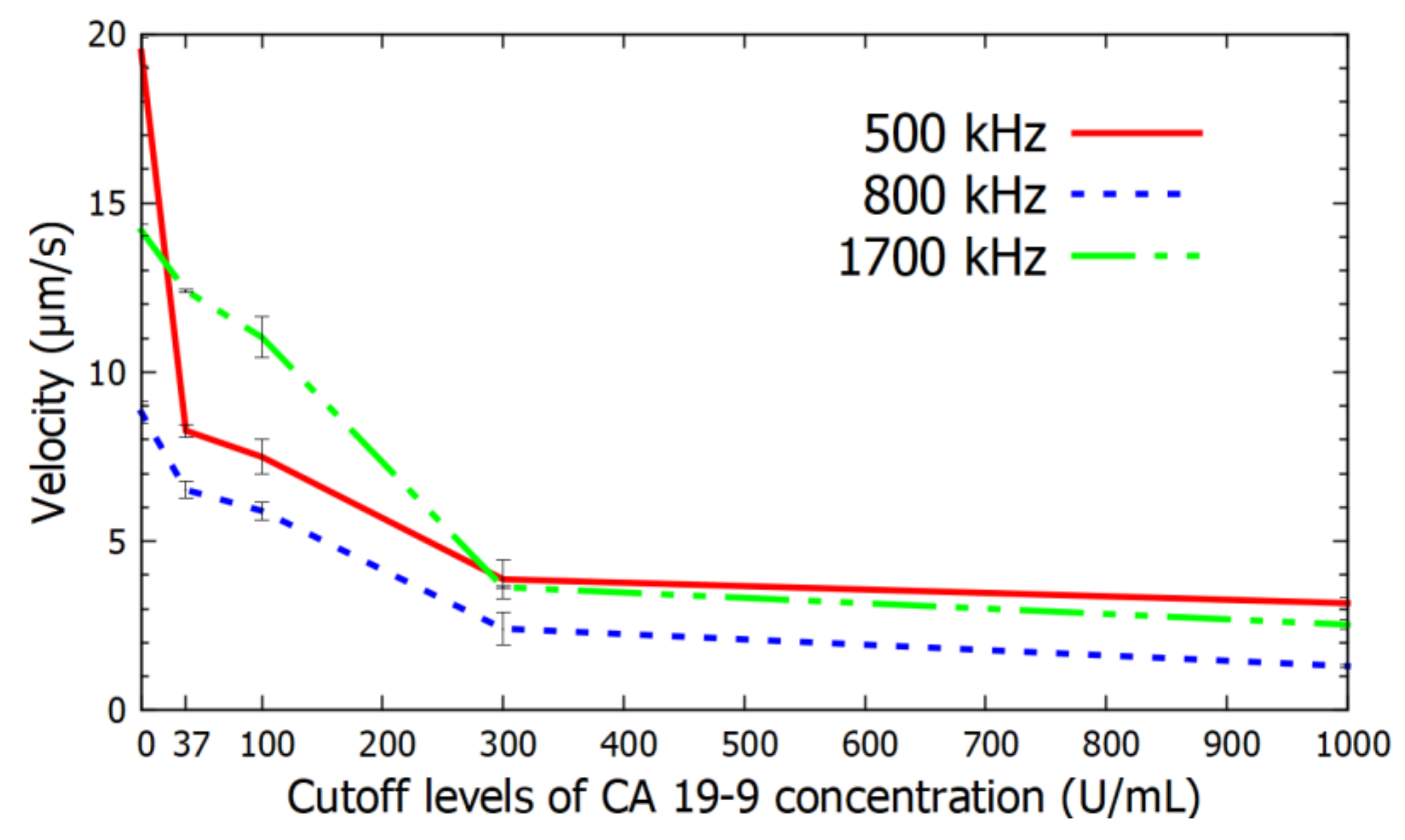
In Figure 6, we show results of the drift velocity due to negative DEP as a function of the concentration of CA 19-9 for three different frequencies. We observed that that the drift velocity due to DEP is strongly dependent on both the frequency and the concentration of CA 19-9 in the cutoff levels that are useful in the prognosis of pancreatic cancer.

5. Discussion

We demonstrated that negative DEP spectroscopy can be used as the transduction mechanism to accurately detect the concentration of CA 19-9, which is a pancreatic cancer biomarker. We measured the negative DEP spectrum using real-time image processing to detect the velocity in which dielectric spheres functionalized with monoclonal antibody to CA 19-9 are repelled by an interdigitated electrode array due to DEP as a function of the frequency. We showed that DEP spectroscopy has sufficient sensitivity to detect the various cutoff levels of CA 19-9 that can enable this method to be used in the diagnosis and in the monitoring of pancreatic cancer. The drift velocity due to negative DEP was calculated for the frequency range from 500 kHz to 2000 kHz. PM with 750 nm diameter were imaged using a side illumination technique to detect the Mie scattering produced by the PM. The change in the DEP spectrum with the binding of even a small concentration of CA 19-9 to the conjugated antibody binding sites on the PM arose from the changes in the distribution of the ions from the solution close to the PM surfaces in the presence of the target molecules. Therefore, there is no need to use fluorescent labels conjugated to CA 19-9 to detect the presence of the target molecules. The use of fluorescent labels, on the other hand, not only requires a washing phase to remove the unbound fluorescent molecules, but the quantification of the concentration with that method also requires a careful calibration of the light source and the photodetector sensitivity. Since the measurement using negative DEP spectroscopy is based on the drift velocity of the particles due to DEP as a function of the frequency of the external electric field, this measurement does not depend on the light intensity, the number of PM, and the sensitivity of the camera, as long as the experimental setup enables the calculation of the center of mass of the PM.

6. Conclusions

We demonstrated that DEP spectroscopy is an effective label-free transduction mechanism for the detection of the cut off levels of the pancreatic cancer biomarker CA 19-9 in PBS buffer. The velocity of repulsion due to DEP on a set of PM functionalized to a monoclonal antibody to CA 19-9 was measured at 0 U/mL, 37 U/mL, 100 U/mL, 300 U/mL, and 1000 U/mL concentration cutoff levels of CA 19-9 at the frequency range from 0.5 to 2 MHz. The proposed method is an effective transduction mechanism for the detection of the cutoff levels of CA 19-9, which can be used in early stage diagnosis and in the prognosis of pancreatic cancer. We plan to extend this study by investigating the use of this biosensing method to detect the concentration level of CA 19-9 in spiked serum samples and in human samples. We also plan to design an electrode for the sensor that enables the automatic detection of the region of interest in the field of view of the biosensor. This modification will eliminate the need of having an expert technician to align the selected region for image processing with the region of the electrode that has the highest gradient of the electric field.

Author Contributions

Conceptualization, I.T.L.J. and D.N.; Formal analysis, F.D.G.; Investigation, F.D.G. and L.V.; Methodology, F.D.G., L.V., D.N. and I.T.L.J.; Project administration, I.T.L.J.; Writing—original draft, F.D.G.; Writing—review & editing, L.V., D.N. and I.T.L.J.

Funding

This research was funded by the NDSU Development Foundation.

Conflicts of Interest

The authors declare no conflict of interest.

References

  1. Kamisawa, T.; Wood, L.D.; Itoi, T.; Takaori, K. Pancreatic cancer. Lancet 2016, 388, 73–85. [Google Scholar] [CrossRef]
  2. Muniraj, T.; Jamidar, P.A.; Aslanian, H.R. Pancreatic cancer: A comprehensive review and update. Dis. Mon. 2013, 59, 368–402. [Google Scholar] [CrossRef] [PubMed]
  3. Henry, N.L.; Hayes, D.F. Cancer biomarkers. Mol. Oncol. 2012, 6, 140–146. [Google Scholar] [CrossRef] [PubMed] [Green Version]
  4. Del Villano, B.C.; Brennan, S.; Brock, P.; Bucher, C.; Liu, V.; McClure, M.; Rake, B.; Space, S.; Westrick, B.; Schoemaker, H.; et al. Radioimmunometric assay for a monoclonal antibody-defined tumor marker, CA 19-9. Clin. Chem. 1983, 29, 549–552. [Google Scholar] [PubMed]
  5. Chang, J.C.; Kundranda, M. Novel Diagnostic and Predictive Biomarkers in Pancreatic Adenocarcinoma. Int. J. Mol. Sci. 2017, 18, 667. [Google Scholar] [CrossRef] [PubMed]
  6. Distler, M.; Pilarsky, E.; Kersting, S.; Grützmann, R. Preoperative CEA and CA 19-9 are prognostic markers for survival after curative resection for ductal adenocarcinoma of the pancreas—A retrospective tumor marker prognostic study. Int. J. Surg. 2018, 11, 1067–1072. [Google Scholar] [CrossRef] [PubMed]
  7. Duffy, M.J.; Sturgeon, C.; Lamerz, R.; Haglund, C.; Holubec, V.L.; Klapdor, R.; Nicolini, A.; Topolcan, O.; Heinemann, V. Tumor markers in pancreatic cancer: A European Group on Tumor Markers (EGTM) status report. Ann. Oncol. 2009, 21, 441–447. [Google Scholar] [CrossRef] [PubMed]
  8. Poruk, K.E.; Gay, D.Z.; Brown, K.; Mulvihill, J.D.; Boucher, K.M.; Scaife, C.L.; Firpo, M.A.; Mulvihill, S.J. The Clinical Utility of CA 19-9 in Pancreatic Adenocarcinoma: Diagnostic and Prognostic Updates. Curr. Mol. Med. 2013, 13, 340–351. [Google Scholar] [PubMed]
  9. Steinberg, W. The Clinical Utility of the CA 19-9 Tumor-Associated Antigen. Am. J. Gastroenterol. 1990, 85, 350–355. [Google Scholar] [PubMed]
  10. Baryeh, K.; Takalkar, S.; Lund, M.; Liu, G. Development of quantitative immunochromatographic assay for rapid and sensitive detection of carbohydrate antigen 19-9 (CA 19-9) in human plasma. J. Pharm. Biomed. Anal. 2017, 146, 285–291. [Google Scholar] [CrossRef] [PubMed]
  11. Passerini, R.; Cassatella, M.C.; Boveri, S.; Salvatici, M.; Radice, D.; Zorzino, L.; Galli, C.; Sandri, M.T. The pitfalls of CA19-9: Routine testing and comparison of two automated immunoassays in a reference oncology center. Am. J. Clin. Pathol. 2012, 138, 281–287. [Google Scholar] [CrossRef] [PubMed]
  12. Yang, Y.; Ozsoz, M.; Liu, G. Gold nanocage-based lateral flow immunoassay for immunoglobulin G. Mikrochim. Acta 2017, 184, 2023–2029. [Google Scholar] [CrossRef] [PubMed]
  13. Wu, T.; Zhang, Y.; Wei, D.; Wang, X.; Yan, T.; Du, B.; Wei, Q. Label-free photoelectrochemical immunosensor for carcinoembryonic antigen detection based on g-C3N4 nanosheets hybridized with Zn0.1Cd0.9S nanocrystals. Sens. Actuators B Chem. 2018, 256, 812–819. [Google Scholar] [CrossRef]
  14. Chung, J.W.; Bernhardt, R.; Pyun, J.C. Additive assay of cancer marker CA 19-9 by SPR biosensor. Sens. Actuators B Chem. 2006, 118, 28–32. [Google Scholar] [CrossRef]
  15. Kirmani, S.A.M.; Gudagunti, F.D.; Velmanickam, L.; Nawarathna, D.; Lima, I.T., Jr. Dielectrophoretic spectroscopy using a microscopic electrode array. In Proceedings of the SPIE—BiOS Photonics West, San Francisco, CA, USA, 28 January–2 February 2017; SPIE: San Francisco, CA, USA, 2017; Volume 10068, p. 100680Z. [Google Scholar]
  16. Kirmani, S.A.M.; Gudagunti, F.D.; Velmanickam, L.; Nawarathna, D.; Lima, I.T., Jr. Negative dielectrophoresis spectroscopy for rare analyte quantification in biological samples. J. Biomed. Opt. 2017, 22. [Google Scholar] [CrossRef] [PubMed]
  17. Abd Rahman, N.; Ibrahim, F.; Yafouz, B. Dielectrophoresis for Biomedical Sciences Applications: A Review. Sensors 2017, 17, 449. [Google Scholar] [CrossRef] [PubMed]
  18. Jones, T.B. Basic theory of dielectrophoresis and electrorotation. IEEE Eng. Med. Biol. Mag. 2003, 22, 33–42. [Google Scholar] [CrossRef] [PubMed]
  19. Qian, C.; Huang, H.; Chen, L.; Li, X.; Ge, Z.; Chen, T.; Yang, Z.; Sun, L. Dielectrophoresis for Bioparticle Manipulation. Int. J. Mol. Sci. 2014, 15, 18281–18309. [Google Scholar] [CrossRef] [PubMed] [Green Version]
  20. Pethig, R. Dielectrophoresis: Status of the theory, technology, and applications. Biomicrofluidics 2010, 4, 1–35. [Google Scholar] [CrossRef]
  21. Viefhues, M.; Eichhorn, R. DNA dielectrophoresis: Theory and applications a review. Electrophoresis 2017, 38, 1483–1506. [Google Scholar] [CrossRef] [PubMed]
  22. Lima, I.T., Jr.; Nawarathna, D.; Gudagunti, F.D.; Velmanickam, L. Method for Detecting and Quantifying Biological Molecules Using Dielectrophoresis. Provisional. U.S. Patent Ser. No 62/622,508, 26 January 2018. [Google Scholar]
  23. Khoshmanesh, K.; Nahavandi, S.; Baratchi, S.; Mitchell, A.; Kalantar-zadeh, K. Dielectrophoretic platforms for bio-microfluidic systems. Biosens. Bioelectron. 2011, 26, 1800–1814. [Google Scholar] [CrossRef] [PubMed]
  24. Kawabata, T.; Washizu, M. Dielectrophoretic detection of molecular bindings. IEEE Trans. Ind. Appl. 2001, 37, 1625–1633. [Google Scholar] [CrossRef]
  25. Ramón-Azcón, J.; Yasukawa, T.; Mizutani, F. Sensitive and spatially multiplexed detection system based on dielectrophoretic manipulation of DNA-encoded particles used as immunoreactions platform. Anal. Chem. 2011, 83, 1053–1060. [Google Scholar] [CrossRef] [PubMed]
  26. Viefhues, M.; Regtmeier, J.; Anselmetti, D. Fast and continuous-flow separation of DNA-complexes and topological DNA variants in microfluidic chip format. Analyst 2013, 138, 186–196. [Google Scholar] [CrossRef] [PubMed]
  27. Velmanickam, L.; Laudenbach, D.; Nawarathna, D. Dielectrophoretic label-free immunoassay for rare-analyte quantification in biological samples. Phys. Rev. E Stat. Nonlinear Soft Matter Phys. 2016, 94, 1–6. [Google Scholar] [CrossRef] [PubMed]
  28. Pethig, R.; Smith, S. Introductory Bioelectronics for Engineers and Physical Scientists; Willey: West Sussex, UK, 2013; ISBN 9781119970873. [Google Scholar]
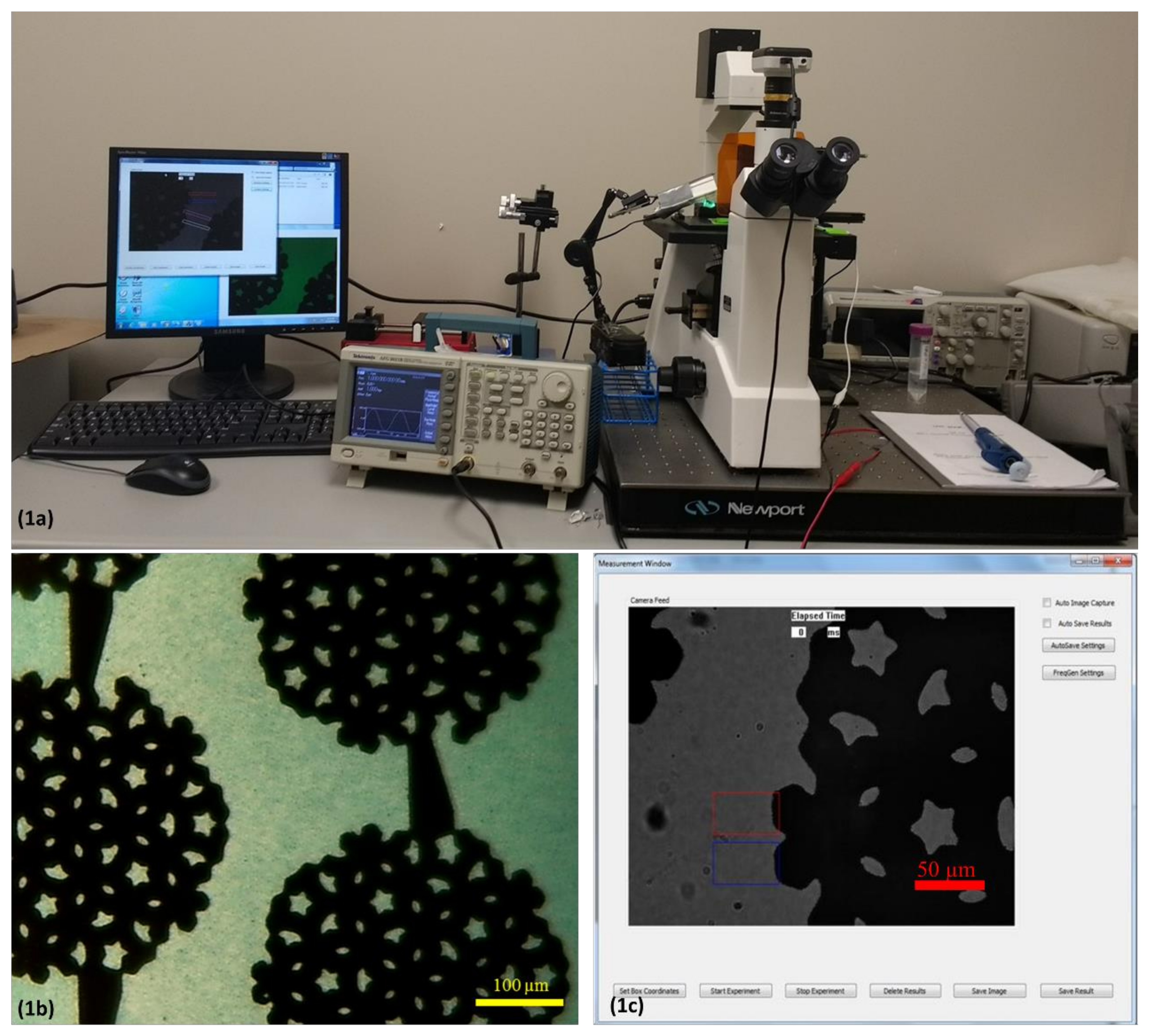
Figure 1. (a) Experimental setup of the sensor prototype. (b) Interdigitated electrode used in the experiments. The electrode is visible as the darker region in the picture. Scale bar indicates 100 µm. Multi-colored hollow rectangles depict the regions of interest for measurements and analysis. (c) Interface of Microsoft Windows application for dielectrophoresis (DEP) spectroscopy.
Chemosensors 06 00033 g001
Figure 2. 19-9 Schematic representation of the sample preparation (Biotinylated polystyrene microspheres (PM) + Streptavidin + Biotinylated CA 19-9 Monoclonal Antibody) with the antigen Native Protein CA 19-9, assuming binding in all the available sites of the antibody.
Chemosensors 06 00033 g002
Figure 3. Demonstration of negative DEP effect through time-lapse images captured through the DEP spectroscopy application (Assuming t = 0 when electric field frequency is changed to induce negative DEP): (a) t = 0 ms and (b) t = 40 ms. The concentration of CA 19-9 in this solution is 37 U/mL. The interdigitated electrode is visible as darker region in the picture. The bright layer visible on the edge of the electrode is formed by the accumulation of the sample. As the frequency is changed to induce negative DEP the antigen-bound PM are repelled from the electrode. For 60 s prior to the image (a), a 10 V peak-to-peak electric field at 10 kHz, which produces positive DEP, was applied to the electrodes. Then, the frequency of the electric field increased to 500 kHz, producing negative DEP. The scale bar on both the figures indicates 50 µm.
Chemosensors 06 00033 g003
Figure 4. Light intensity versus pixel position at t = 0 ms, when negative DEP is applied, and at t = 80 ms for the 37 U/mL in 10 µL. The electrode is located on the right side of the PM layer, as shown in Figure 3.
Chemosensors 06 00033 g004
Figure 5. Negative DEP spectrum curves for cutoff levels of CA 19-9 for the detection of pancreatic cancer at 0 U/mL, 37 U/mL,100 U/mL, 300 U/mL, and 1000 U/mL. The error bars show the confidence interval in each individual measurement that were calculated using six measurements per frequency.
Chemosensors 06 00033 g005
Figure 6. Variation of the drift velocity due to negative DEP with the cut off levels of concentration of CA 19-9 for the frequency range at 500 kHz, 800 kHz, and 1700 kHz.
Chemosensors 06 00033 g006