Article

Research on Deep-Hole Cutting Blasting Efficiency in Blind Shafting with High In-Situ Stress Environment Using the Method of SPH

1
Faculty of Land Resources Engineering, Kunming University of Science and Technology, Kunming 650093, China
2
Yunnan Key Laboratory of Sino-German Blue Mining and Utilization of Special Underground Space, Kunming University of Science and Technology, Kunming 650093, China
3
Faculty of Electric Power Engineering, Kunming University of Science and Technology, Kunming 650500, China
4
City Collage, Kunming University of Science and Technology, Kunming 650051, China
5
Yuxi Dahongshan Mining Co. Ltd., Yuxi 650302, China
*
Authors to whom correspondence should be addressed.
Disclosure: Zhiyu Zhang is the co-first author. Hongchao Li is co-corresponding authors.
Mathematics 2021, 9(24), 3242; https://doi.org/10.3390/math9243242
Submission received: 1 November 2021 / Revised: 1 December 2021 / Accepted: 8 December 2021 / Published: 14 December 2021

Abstract

:
This article aiming at the lack of research on the influence of rock clamp production on cutting blasting under high in-situ stress conditions and the lack of rock damage criteria for RHT constitution in numerical simulation. Combined with the critical rock damage criterion and the embedded function of RHT constitution, the criterion for determining the critical damage of rock in RHT constitutive was studied, and the mechanical parameters of Metamorphic sodium lava were substituted to obtain the critical damage threshold of rock in numerical simulation. The smooth particle hydrodynamics (SPH) method was used to numerically simulate and analyze the influence of different rock clamping coefficients on the rock damage range and the cavity area in the cutting blasting. The stress state applied by the numerical simulation was inversely deduced by the field test scanning results to simulate the rock clamping coefficient Kr at the corresponding depth. The relationship between the cavity area Sc and the free surface distance Df is analyzed and established. The results show that the rock clip production has an inhibitory effect on the development and propagation of blast-induced cracks. The stress applied in the numerical simulation affects the range and development degree of cracks, and the cracks generated by the explosion are mainly circumferential cracks. The larger coefficient of rock clip production, the more obvious the inhibitory effect on cut blasting, the less the blast-induced cracks and the smaller the rock damage circle. The fitting results show that the curve fitting degree is about 0.94, which proves the accuracy of Sc-Df curve, and provides important reference value for the design of one-time completion blasting of upward blind shaft.

1. Introduction

The demand for metal materials in various industries is gradually increasing as science and technology advance. After years of mining, the mineral endowment in the shallow surface is diminishing, and the mine construction is gradually shifting towards the deep part of the mine. Deep rock is frequently accompanied by high in-situ stress, and drilling and blasting are currently the main methods of deep mining excavation. Scholars through a large number of field tests concluded that deep rock blasting is the main source of mining. As a result, it is critical to investigate the impact of high in-situ stress on the construction effects of rock crushing, blasting into shafts and roadway excavation.
Currently, many scholars have carried out a series of field tests and numerical simulations for rock blasting under high in-situ conditions [1,2,3,4,5]. Yan et al. [6] used wavelet packet analysis to analyze the vibration signals during tunnel blasting excavation under high in-situ stress conditions and obtained the energy distribution of the vibration signals in different frequency bands. Wei et al. [7] analyzed the effect of in-situ stress on the crack extension by simulating the tangential pack blasting under different in-situ stress conditions based on a damage mechanics model. Yang et al. [8,9] established a computational model for double-hole blasting of high in-situ stress rock masses based on the SPH-FEM algorithm, and concluded that the hole spacing should be appropriately shortened under high-stress conditions to facilitate crack expansion by analyzing the stress field distribution as well as the dynamic evolution process. Liu et al. [10] used the hollow core envelope method to measure the in-situ stress in the roadway and combined it with FLAC3D software for stability analysis to derive the influence of the tectonic stress field on the roadway. Dai [11] based on blasting funnel theory, the study of high-stress roadway avalanche blasting, and concluded that the choice of high explosive velocity explosives under high in-situ stress is more effective. Tang et al. [12] based on the decay of blasting frequency in perimeter rock excavation to define the damage variables and derive the decay law of blasting damage amount with the change of blast core distance. LI et al. [13,14,15,16] investigated the effect between dynamic unloading effects of in-situ stress and high in-situ stress conditions during blasting excavation using FLAC3D and PFC5.0 numerical software. Yang et al. [17] investigated the relationship between the lateral pressure coefficient and the effect of unloading rate and damage extent using the finite difference method, and verified its accuracy by field testing. Luo et al. [18] proposed a blast damage simulation method based on normal impact load to study the blast damage incubation mechanism under different stress conditions, and concluded that a certain degree of in-situ stress plays a suppressive role on blast damage. Lu et al. [19,20] used LS-DYNA finite element simulation software to simulate the confining effect of rock tunnel to be excavated by applying nodal reaction forces to analyze the damaging effect of blasting excavation on the surrounding rock, and concluded that the damaged area was mainly caused by the initial stress redistribution in the surrounding rock, and the blast load action increased its extent. Li et al. [21] used numerical simulation methods to introduce damage state indicators and proposed two indicators to reflect the effect of trenching blasting, and studied the effect of stress wave loading rate and in-situ stress on cutting blasting. In the above-mentioned analytical studies, for the study of rock mass blasting under high in-situ stress conditions, the rock mass damage is mainly reflected by instrument measurement and numerical simulation. However, there are different constitutive models such as TCK, HJC, Yang, RHT, etc. in numerical simulations, and their damage assessment criteria for specific intrinsic structures have not been studied much. In addition, there are few studies on the effect of rock entrapment on cavity formation and damage patterns in trenching and blasting.
In summary, this paper will employ the rock critical damage parametric theory and the RHT damage model to establish the RHT intrinsic critical damage assessment criteria based on the embedded plastic strain and ultimate strain equations in the RHT constitution. Furthermore, it is impossible to predict the results of the upward-oriented once-in-a-whole cutting blasting into the cavity state and crack expansion under high in-situ stress conditions. To study the characteristic law of rock damage and cutting cavity formation under high in-situ stress in upward blind cutting blasting using the smooth hydrodynamic method (SPH method), and the results were compared with the field cavity scanning results to verify the accuracy of the numerical simulation, and the inverse extrapolation of the rock clamping performance in the test area was performed based on the field test results to investigate the influence law of rock clamping production.

2. Establishment of RHT Constitutive Damage Criterion

2.1. Blast Damage Variable Definition

According to the research results of previous scholars [22], the damage of the rock body under the blast load is the combined effect of the blast pressure, the expansion of the blast-generated gas and the unloading stress, while taking into account the anisotropy of the rock body, the expansion of primary cracks and the development of new cracks. The commonly used rock damage variables are:
D = 1 E ¯ E
where: D is the rock damage variable; E ¯ is the equivalent modulus of elasticity of the damaged rock after blasting; E is the modulus of elasticity of the intact rock before blasting.
According to the elastic stress wave theory, there is a certain relationship between the elastic modulus of rock and the longitudinal wave velocity before and after blasting excavation, as in Equations (2) and (3):
E = ρ c p 2 1 μ 1 2 μ 1 μ
E ¯ = ρ ¯ c p ¯ 2 1 + μ ¯ 1 2 μ ¯ 1 μ ¯
where: ρ, ρ ¯ represent the density of the rock before and after blasting excavation, kg/m3; cp, c ¯ p are the longitudinal velocity of the rock before and after blasting, m/s; μ, μ ¯ are the Poisson’s ratio of the rock before and after blasting excavation, respectively.
In this paper, it is assumed that the density and Poisson’s ratio of the rock before and after blasting do not change, i.e.,: ρ = ρ ¯ , μ = μ ¯ . Therefore, the finishing of Equations (2) and (3) into Equation (1) can be obtained as follows:
D = 1 c p ¯ c p 2
where the rate of change of the longitudinal wave velocity of the rock body before and after blasting η can be expressed by Equation (5):
η = c p c p ¯ c p = 1 c p ¯ c p
Thus, the damage variable D can be integrated as:
D = 1 1 η 2
Wu [23] investigated the damage failure behavior of rock materials based on the existing research results for the rock damage variable D combined with the damage failure criterion of rock materials, and the damage value corresponding to the peak strength of the rock material is regarded as the rock critical damage parameter Dcr, while the material damage is mainly caused by the plastic deformation of the material. Therefore, the relationship between the plastic strain of the rock and the critical damage parameters of the rock can be expressed by Equation (7):
D c r = ε p ε m a x
where: εmax, εp are the peak strain and plastic strain under uniaxial compression, respectively.

2.2. Blast Damage Action Zoning

The primary rock mass has initial damage D0 due to the presence of joints, fissures and structural surfaces, etc. Explosive blast generates shock waves to make the blast hole wall around a certain range of rock crushing, the crushing area rock damage variable D2 = 1, outside the crushing zone is considered as the rock fracture and damage zone (see Figure 1), and its different zoning damage variables are listed in Table 1:

2.3. RHT Constitutive Damage Criterion

The RHT damage constitution was chosen for this numerical simulation, which was proposed by Riedel, Hiermaier, and Thoma in 1997 based on the HJC constitution, by introducing the elastic limit surface, failure strength surface, and residual strength surface to describe the relationship between the elastic limit strain, material failure strength, and residual strength and hydrostatic pressure [24].
The RHT constitutive model is defined for the damage parameter D as:
D = Δ ε p / ε p f
Which:
Δ ε p = ε p f ε p
ε p f = D 1 p * 1 D p t * D 2 ε m p p * 1 D p t * + ε p m / D 1 1 / D 2 1 D p t * + ε p m / D 1 1 / D 2 > p *
In Equations (8)–(10): Δεp is the equivalent plastic strain increment; εpf is the final failure equivalent plastic strain; εpm is the minimum equivalent plastic strain when the material is damaged; D1, D2 are the initial damage parameters of the material and the complete damage parameters of the material, respectively; p* is rock shear strength and pt* is failure cut-off pressure.
And for the material in the p*, pt* is usually expressed using the Formulas (11) and (12):
p * = p f c
p t * = F r Q 2 f s * f t * 3 Q 1 f t * Q 2 f s *
Which:
Q 1 = R 3 π 6 , 0
Q 2 = Q p * = Q 0 + B p *
R 3 θ , p * = 2 1 Q 2 2 c o s θ + 2 Q 2 1 4 1 Q 2 2 c o s 2 θ + 5 Q 2 2 4 Q 2 4 1 Q 2 2 c o s 2 θ + 1 2 Q 2 2
In Equations (11)–(15): p is the pressure on the material, MPa; fc is the uniaxial compressive strength of the rock, MPa; Fr is the dynamic strain rate increment factor; Q0 is the initial tensile-compression radial ratio parameter; fs*, ft* are the tensile and shear strength of the concrete relative to the compressive strength; B represents the Rhodes angle-related parameter.
The dynamic strain rate increment factor is related to the material strain rate and shear strength, and its expression is:
F r = F r c F r c 3 p * F r c F r t F r c / F r c + F t c f t * F r t 3 p * F r c F r c > 3 p * F r t f t * F r t f t * > 3 p *
Frc and Frt represent the dynamic compression strain rate enhancement factor and dynamic tensile strain rate enhancement factor, respectively.
Where ε ˙ 0 c and ε ˙ 0 t are the compressive reference strain rate and tensile reference strain rate, respectively, and the values are 3.0 × 10⁻⁵ s−1 and 3.0 × 10⁻⁶ s−1 for the given parameters of the present structure, while the expressions of the compressive strain rate index βc and tensile strain rate index βt are [19]:
β c = 4 20 + 3 f c
β t = 2 20 + f c
The elastic limit surface in the RHT structure is set by the equation of the elastic limit surface and the “cap function” that constrains the overflow of the elastic limit stress in the material under high hydrostatic conditions. Where the elastic limit surface equation is:
σ e l * p , θ , ε · = σ y * × F e × F c p *
The elastic strength parameter used above is given by:
F e = g c * g c * 3 p * F r c g c * g t * g c * / F r c g c * + F r t g t * f t * g t * 3 p * F r c g c * F r c g c * > 3 p * F r t g t * f t * F r t g t * f t * 3 p *
Fc is the “cap function”, which is introduced to reduce the volume expansion caused by shear and to limit the elastic limit stress of the material at high hydrostatic pressure, while the cap of the yield surface is represented by:
F c = 1 p * p c * 1 p * p u * p c * p u * 2 p c * > p * > p u * 0 p u * p *
In Formulas (22) and (23): gc* and gt* are compression yield surface parameters and tensile yield surface parameters, respectively.
Which:
g c * = f c , e l / f c
g t * = f t , e l / f t
Form (24), (25): fc,el and ft,el are uniaxial compressive ultimate stress and uniaxial tensile elastic ultimate stress, respectively.
According to the above RHT embedded formulas, it can be seen that the description of the damage parameters in the present structure model only has the initial damage value D1 and the complete damage value D2, and there is no criterion for determining the critical damage of the rock. Therefore, to establish the mathematical relationship between the rock critical damage parameters in the RHT constitution and the parameters in the principal structure model, the RHT principal structure-function is organized according to Equation (7), and the state of the rock at the beginning of crushing is selected as the rock critical damage threshold judging criterion. The values of each of the above equations of state taken at the start of crushing conditions are collated as follows: Fr = Frc, Fe = gc*, Fc = 1, so the plastic strain and ultimate strain in Equation (7) can be collated as:
ε p = f c f c × R 3 π 6 × F r × g c * 3 G ζ
ε m a x = D 1 p * 1 D c r F r Q 2 f s * f t * 3 Q 1 f t * Q 2 f s *
The lithology of the test area is mainly Metamorphic sodium lava, and the parameters of the RHT intrinsic model of metamorphic lava can be obtained through relevant mechanical tests and theoretical calculations, see Table 2.
The determined RHT constitutive parameters of the variable metamorphic lava were substituted into Equations (7), (26) and (27) to obtain the critical parameter Dcr = 0.106 for the RHT intrinsic damage of the variable metamorphic lava in this numerical simulation, and this was used as the criterion for determining the rock damage in the subsequent numerical simulation.

3. Field Cutting Blasting Test

The test area is located in Yunnan Dahongshan iron ore mine 400 m platform 8# penetration. The roadway size is 4 m × 3 m, the site construction layout is shown in Figure 2a. Furthermore, the DL421 cart was used for the preliminary small-diameter precision drilling operation, with an empty hole depth of 9.5 m, a loaded hole depth of 10 m, a fill length of 0.5 m, and a hole diameter of 106 mm. The empty hole diameter was expanded from 105 mm to 205 mm by using a T150 drilling rig with reaming bit. The explosive was injected into the charging hole through the charging device (Figure 2b) by wind pressure, and the ANN-2 viscous ammonium nitrate explosive was adhered to the charging hole due to its own characteristics. The charge method adopts the coupling charge method, and the explosive is detonated by detonating cord and a millisecond delay detonator. The field after charge is shown in Figure 2c. The blasting was carried out by bottom detonation, and the blasting effect is shown in Figure 2d. After blasting, the broken rock formed the blasting pile as shown in Figure 2e. Through observation, it can be seen that the rock fragmentation in the blasting pile is small, indicating that the dosage is too much. In further research, the dosage can be adjusted by realizing the interval charge, whereas the overall slot cavity blasting effect is shown in Figure 2f after scanning of the blasted slot cavity using the winged HM100 special UAV.
Since there is only one free surface in the cutting blast, the rock clip production cost has a great influence on the blasting effect, and the rock clip production cost increases linearly with the depth of the cutting hole. In addition, under medium to high in-situ stress conditions, due to the complexity of the coupling mechanism between blast load and rock clamping mechanism, there is no effective means to measure rock clamping performance at the test site. Therefore, the slot cavity area was scanned by using UAV for every 0.5 m section of the slot cavity. To analyze the effect of rock clamping on the effect of cutting blasting, numerical simulation was used to simulate rock clamping by changing the stress state of the numerical model to approximate the field scan results, and the field section scan results at different depths are shown in Figure 3.
It can be seen from Figure 3 that the rock clamping cost increases as the depth of the slot cavity increases, and the area of the slot cavity at the wellhead is larger at 0–0.5 m because it is close to the free surface. Then the area of the slot cavity decreases gradually at 1–8.5 m with the increase of the rock clamping cost and the coupling effect of the empty hole compensation and the rock clamping cost, but the decay of the slot cavity area is not large. However, because there are no effective and direct measurement methods for the complex mechanism of rock clamping production, this paper will use numerical simulation to invert the rock clip production by changing the stress state, to study the impact law of rock clip production on cutting blasting.

4. Numerical Simulation Analysis for Rock Clip Production

Since rock clamping production cannot be measured directly, such as by indirect methods (e.g., rock wave velocity, stress peak, etc.), the sensors buried near the blasting area will be damaged and costly due to blasting impact and other factors. The measurement points set at the distant end of the blasting area will lead to inaccurate data due to distance attenuation, so this paper will use numerical simulation to model the rock clamping production at different depths and also, numerical simulation to model the hollowing section at different depths, and invert the rock clamping production at the corresponding hollowing depth by changing the stress state, to study its influence on the rock damage and cavity-forming law.

4.1. Numerical Model

The geometric model and numerical model are shown in Figure 4a,b. The numerical model is designed by LS-DYNA finite element analysis software, which mainly consists of rock and explosive. The numerical simulation mainly focuses on the analysis of the rock clip production, the formation of the slot cavity and the rock damage in the hollowing section at different depths. The numerical model is a quasi-3D model with the size of 5 m × 5 m × 0.01 m, the diameter of the charge hole Φ = 0.1 m, the diameter of the hollow hole Φ = 0.2 m, and the six hollow holes in the form of barrel type hollowing with the hole spacing d = 0.35 m.

4.2. Stress Application Method

The method of applying stress on the model boundary in this simulation is shown in Figure 5. In order to prevent the particles near the model boundary from being truncated by the kernel function in the calculation process, it is necessary to set multi-layer virtual particles outside the model boundary and generate five-layer virtual particles through the keyword *BOUNDARY_SPH_SYMMETRY_PLANE in the boundary mirror. The density, velocity and mass of virtual particles are the same as those of real particles. The stress is linearly increased to the confining pressure p0 by using the relevant keywords, so that the model is in a quasi-static dynamic load state. The stress expression of the virtual particle in the stress loading process is:
σ t = t t 0 p 0 , t t 0 p 0 , t > t 0

4.3. Stress Condition Analysis

Deep rock blasting is mainly achieved through the combined effect of explosive blast load and high in-situ stress, so horizontal in-situ stress σh and vertical in-situ stress σv need to be considered, and E.T. Brown et al. [25] summarized the fitting equation between vertical stress σv and depth H:
σ v = 0.027 H
While the lateral pressure coefficient K between horizontal in-situ stress and vertical in-situ stress reveals a certain relationship with depth, Zhao et al. compiled the relationship between the lateral pressure coefficient K and depth H for magmatic rocks in China based on a large amount of data as follows:
K = 200 H + 0.7
It is difficult to obtain accurate data due to high consumables, improper measurement and instrument error in deep in-situ stress measurement. This paper will impose stress based on previous scholars’ summaries of the macroscopic in-situ stress field distribution law and invert the distribution law based on field data for rock clip production in the test area. Once again, from the geological data provided by the mine geology department, the test area is 400 m platform 8# penetration, the burial depth is about 640 m, and the vertical in-situ stress σv = 17.28 MPa and horizontal in-situ stress σh = 17.5 MPa can be calculated with Equations (29) and (30).

4.4. Explosive Constitution

Explosives provided by the mine ANN-2 viscous ammonium nitrate explosives, explosives parameters are shown in Table 3. The numerical simulation of explosives used through the keyword *MAT_HIGH_EXPLOSIVE_BURN to achieve, while introducing the JWL equation of state to describe the explosive process of volume, pressure and energy change characteristics. The expression equation is given by Formula (29) as:
P = A 1 ω R 1 V e R 1 + B 1 ω R 2 V e R 2 V + ω E 0 V
where: P is the explosive burst pressure, V represents the relative volume of explosives in the burst process, E0 refers to the explosive initialized internal energy, A, B, R1, R2, ω for the material gauge constants.
The explosive parameters and the parameters related to the JWL equation of state can be determined by experimental fitting, and the explosive and JWL equation of state parameters are shown in Table 3.

4.5. Clamping Factor Simulation Analysis

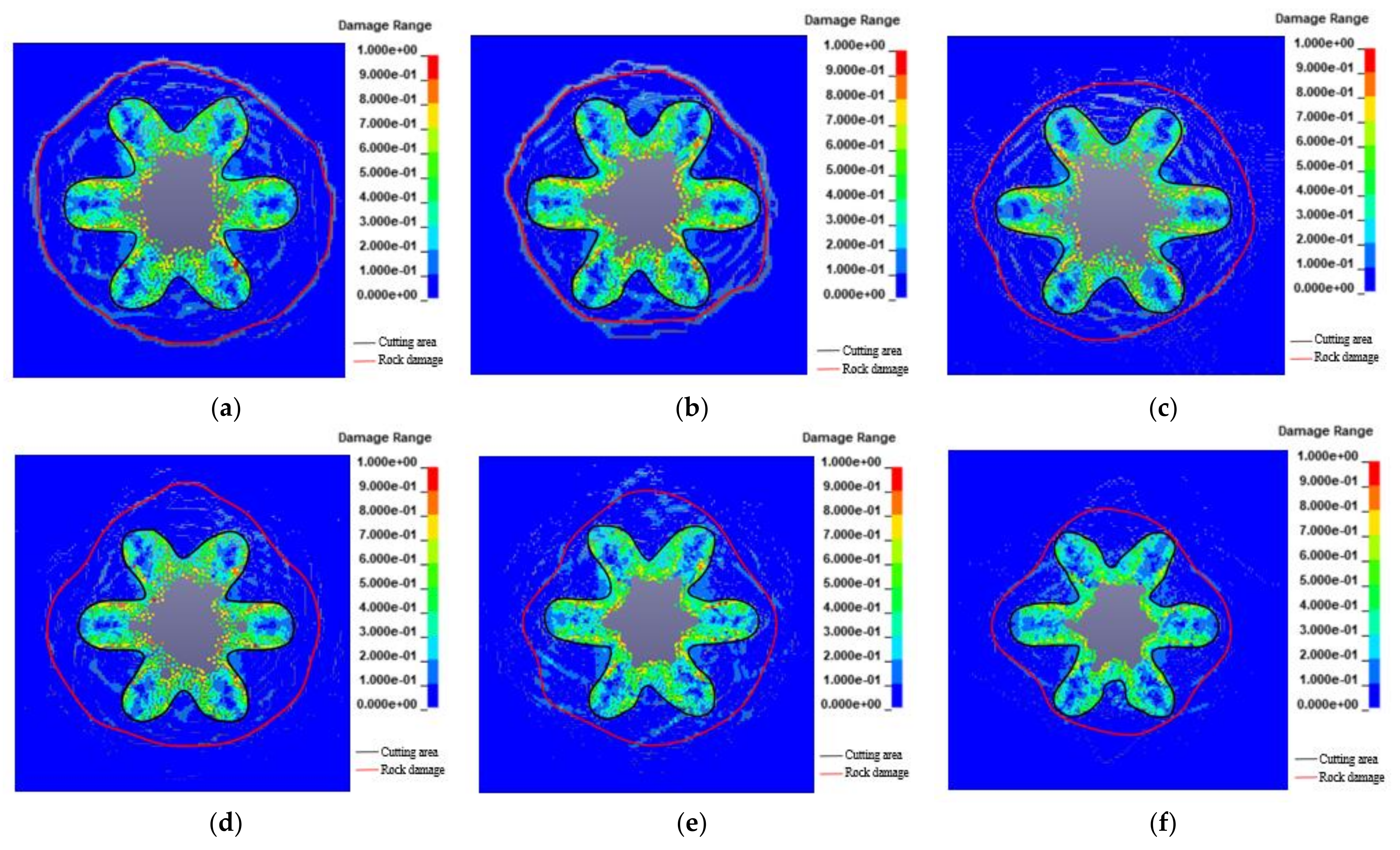
To investigate the effect of various rock clamping production methods on cavity formation and rock damage in cutting blasting. Different rock clips production was applied to the numerical model, and the rock damage circle after blasting was delineated according to the previously determined critical damage parameters. Figure 6a–f show the damage clouds of the cutting wellhead section under different applied stress conditions, respectively.
Figure 6a–f can reveal that, when there is no rock clamping effect, the rock damage range is larger, and the explosion-generated cracks are very visible. The explosion-generated fissures are primarily circular, whiles the rock damage in the region of microfracture development expansion phenomenon is visible and the distribution is more uniform. When the rock clamping is 0.5–2.0, the area of slot cavity and the range of rock damage relative to no rock clamping effect is reduced, then the burst crack length gradually reduced, and rock fracture development, expansion phenomenon is significantly weakened. When the rock clip production is up to 2.5, burst cavity around the surrounding rock damage to a small extent. Obvious explosive cracks are not observed, and mostly in the form of micro-fractures concentrated in the cutting hole near the rock damage range are significantly reduced. Therefore, it can be concluded that as the rock clamping production increases, the slot cavity area and rock damage range gradually decrease under the influence of rock clamping production inhibition. The rock damage range and slot cavity area are then measured and analyzed, and the changing trend is plotted as showed Figure 7.
From the curves, it can be seen that the rock damage extent was reduced by 9.3%, 16.5%, 22.4%, 27.5% and 43.5%, respectively, and the slot cavity area was reduced by 4.4%, 8.0%, 16.9%, 21.3% and 30.1%, respectively, after the rock clamping mechanism was applied. Due to the coupling effect of explosive load and rock clip production, the area of the slot cavity is relatively less affected, while the rock damage is more affected. In addition, the larger the rock clip production, the greater effect on the blasting effect, and the greater inhibition of rock fracture formation and expansion. The main reason is that rock clip production has a certain inhibitory effect on the propagation of explosive stress waves, so the impact of high rock clip production on rock damage is relatively small. The blasting effect on rock damage under the influence of high rock clip production is relatively small, while the rock clip production inhibits the expansion of primary cracks and the development of new cracks in the rock-damaged area. The excavation unloading under the action of blasting load coupling has consumed most of the energy in the process of breaking the surrounding rock between the charge hole and the empty hole. The blasting stress wave energy propagating to the outside of the cutting hole is not sufficient to achieve the effect of crack expansion on the rock outside the empty hole.
The field scan results were compared with the numerical simulation results under different stress conditions applied, and the rock clip production was inferred by varying the stress applied in the numerical simulation to correspond to the depth of the slot cavity. Figure 8 shows some of the numerical simulation comparison.
It can be seen from Figure 8 that the numerical simulation effect is similar to the field test effect, and the simulation effect is more regular because the numerical simulation cannot simulate this property of rock anisotropy. The area of the simulated slot cavity and the area of the scanned slot cavity in the field are counted separately. The simulated area is 0.45, 0.39, 0.16, 0.09 m2, and the scanned area is 0.44, 0.38, 0.15, 0.08 m2, respectively. The numerical simulation fit was 94.5%, which verified the accuracy of the RHT constitutive parameters and the reliability of the numerical simulation.

5. Analysis of the Influence Law of Rock Clamping

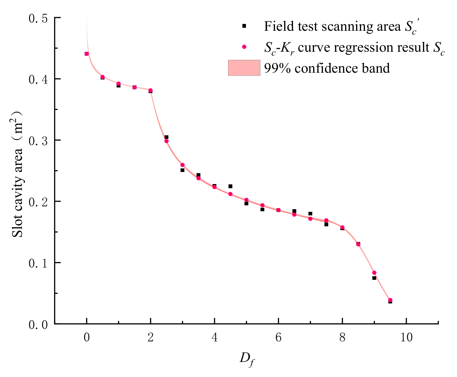
To evaluate the effect of cutting blasting under high rock clip production, the effect of rock clip production on the formation of slot cavity was analyzed from the perspective of the law of rock clip production on the formation of slot cavity. Different stress states were applied to the cavity at different depths to invert the rock clip production at the corresponding depth, and the scanned area of slot cavity in the field at different depths was circled and recorded with the numerical simulation area to draw the cavity-depth curve (see Figure 9a). Here the blasting slot cavity changes are mainly divided into three stages, the depth of hollowing in the 0–2.5 m due to the compensation of the free surface, the slot cavity area is larger and the area decay rate is small; and then the depth of hollowing in 3–7.5 m, as the distance away from the free surface becomes larger, the free surface to provide a gradual reduction in the role of rock clamping becomes larger, so the area of the blasting cavity decay rate increases. When the depth of hollowing is 8–9.5, there is no empty hole around the compensation effect and far from the free surface so it cannot be through the compensation effect. Where the blasting effect can be regarded as an infinite media blasting, the rock clamping effect on the blasting effect is very large, so the slot cavity area decay phenomenon. The stresses applied by the numerical simulation at different depths were counted to find the rock clamping factor Kr at the corresponding depths, and the variation curve of slot area Sc of the hollowing section with the rock clamping factor Kr was plotted (see Figure 9b). The variation law between Sc, Kr and Df was plotted based on the inverse rock clamping stress coefficient Kr at different slot depths, combined with the free surface distance Df (as shown in Figure 9c).
Regarding the Hawk-Brown world stress distribution law and the related analysis method of Kr. Fuchs world stress map WSM2000 [26], the regression analysis of the rock clamping production coefficient Kr with the variation law of the free surface distance Df in this trenching and blasting test was further conducted. According to the change curve of slot cavity area, the change law of 3 different stages is analyzed, and the relationship between rock clamping production coefficient Kr and free surface distance Df is derived as:
K r = F D f = 1.06 + 0.002 D f , 1 1.052 D f , 2 0.01 1.036 D f , 3 0.019 0.5 D f , 1 < 2.5 2.5 D f , 2 < 7.5 7.5 D f , 3 < 10
The regression analysis of the three influential stages of the change of Sc with Kr, and its change law under different stages are:
S c = F K r = 0.381 + 0.108 / 1 + K r , 1 / 1.06 1411.5 0.161 0.148 K r , 2 / 1 0.942 K r , 2 0.264 0.245 K r , 3 / 1 0.923 K r , 3 1.059 K r , 1 < 1.063 1.063 K r . 2 < 1.076 1.079 K r , 3 < 1.080
Combining Equation (31) with Equation (32), the relationship between Sc and Df can be obtained as
S c = F D f = 0.392 D f , 1 0.04 0.5 D f , 1 < 2.5 5.45 5.12 1 e D f , 2 / 0.525 0.25 1 e D f , 2 / 6.96 2.5 D f , 2 < 7.5 0.177 / 1 + e D f , 3 8.97 / 0.44 0.002 7.5 D f , 3 < 10
Therefore, Equation (32) reflects the relationship between Sc and Df. By substituting the free surface distance Df into Equation (32), the regression area Sc′ of the cavity at different free surface distances is obtained and compared with the field test scan results. According to the curve results (Figure 10), it can be seen that the Sc-Kr curve established in this paper has high accuracy in predicting the blasting cavity area values, and its actual values are within 99% confidence interval of the theoretically predicted values, and the goodness of fit of the theoretical curve is about 0.94, which fully proves that the Sc-Kr curve constructed in this paper has high accuracy and provides an important judgment basis for further prediction of blasting effect in trenching and blasting tests.

6. Discussion

In this paper, aiming at the influence of high in-situ stress conditions on the cavity state of the blasting cavity of the one-time well completion cutting in the upward blind shaft, the rock clip production is analyzed. The cavity area measured by UAV scanning after the field test is corrected for the stress state applied in the numerical simulation to achieve the effect close to the field, so as to reverse the rock clip production under different sections. This reverse method is rarely used in previous studies. According to the investigation of the test site, the lithology of the test site is mainly sodium-altered lava. Therefore, the RHT rock parameters used in this test are mainly obtained from the rock parameters obtained from the basic mechanical test of sodium-altered lava and the theoretical calculation. For the cutting effect under other lithology, it will be analyzed in the further test after encountering other lithology and obtaining the corresponding rock parameters in the subsequent test. The numerical model used in numerical simulation is a plate model with unit thickness, which is used to simulate the section cavity in cut blasting. In order to ensure the accuracy of the numerical simulation and be closer to the site, the particle spacing is set to 0.01 m. Therefore, there are more particles in the plane model, about 250,000 particles, so the calculation process is very longer. Due to the influence of the cyclone in the slot cavity, the UAV is scanned at a height of about 0.5 m. Therefore, the Sc-Kr curve is mainly fitted with 20 groups of data, The further experimental study is to overcome the problem of scanning accuracy, improve the scanning accuracy to 0.1 m, and further accurately fit the obtained curve.

7. Conclusions

In this paper, based on the lack of research under high in-situ stress conditions and the lack of criteria for determining the rock damage of the model instantiation, the SPH method and the RHT damage are used to numerically simulate the blasting section of the once-in-a-whole, and to study the cavity formation and the damage law of the cutting blasting under different rock clamping conditions by changing the applied stress state. The following conclusions are drawn from the study:
(1)
Through the calculation of blast breaking strain mechanism and rock damage theory, combined with the embedded function in the RHT damage constitution, the connection between the critical parameters of rock blast damage and material plastic strain, ultimate strain and ontological in the RHT constitution is obtained. The parameters of sodic lava in the numerical simulation are derived based on the RHT constitution parameters of variable sodic lava obtained from mechanical tests and theoretical calculations. The critical threshold of rock damage in the numerical simulation provides a more practical evaluation tool for the damage assessment of RHT constitution in numerical simulation.
(2)
The simulation effect of cutting blasting under different rock clamping conditions shows that: rock clamping production inhibits the development and expansion of blast cracks, the stress applied in the numerical simulation affects the extent of fracture generation and development, and the blast produces mainly circular fractures, the larger the coefficient of rock clamping, the greater the blast inhibition effect. Furthermore, the fewer blast cracks and the smaller the rock damage circle.
(3)
The rock clamping production in the test area was simulated and compared and inferred according to the field test scanning results to approach the rock clamping production in the field test area. The regression analysis was performed for the rock clamping production coefficient Kr for different depths of the slot cavity to obtain the relationship between Kr and the free surface depth Df, and the relationship between the slot cavity area Sc of the hollowing section and Kr, the mathematical relationship between Sc and Df is obtained, and the goodness of fit of the curve is about 0.94, which fully proves that the Sc-Df curve has high accuracy and provides a reference basis for the relevant design of subsequent deep burial projects.
(4)
According to the comparison between the 3D scan data of field trenching and blasting and the numerical simulation results, the average fit of the numerical simulation is 94.5%, which indicates that the RHT parameters have certain accuracy and the numerical simulation has certain reliability.

Author Contributions

Conceptualization, methodology, software, validation, formal analysis, writing—original draft, writing—review and editing: B.S.; investigation, data curation: J.M.; supervision, software: Y.H.; supervision, methodology: H.L.; funding acquisition, project administration: Z.Z.; resources, investigation: J.W. All authors have read and agreed to the published version of the manuscript.

Funding

This research is supported by financial grants from the National Natural Science Foundation of China (52064025, 52164009, 52164010). The authors are very grateful to the financial contribution and convey their appreciation of the organization for supporting this basic research.

Institutional Review Board Statement

Not applicable.

Informed Consent Statement

Not applicable.

Data Availability Statement

Data sharing not applicable.

Conflicts of Interest

The authors declare no conflict of interest.

References

  1. Wang, S.; Tang, Y.; Li, X.; Du, K. Analyses and predictions of rock cuttabilities under different confining stresses and rock properties based on rock indentation tests by conical pick. Trans. Nonferrous Met. Soc. 2021, 31, 1766–1783. [Google Scholar] [CrossRef]
  2. Wang, S.; Li, X.; Yao, J.; Gong, F.; Li, X.; Du, K.; Tao, M.; Huang, L.; Du, S. Experimental investigation of rock breakage by a conical pick and its application to non-explosive mechanized mining in deep hard rock. Int. J. Rock Mech. Min. Sci. 2019, 21, 104063. [Google Scholar] [CrossRef]
  3. Wang, S.; Sun, L.; Li, X.; Wang, S.; Du, K.; Li, X.; Feng, F. Experimental investigation of cuttability improvement for hard rock fragmentation using conical cutter. Int. J. Geomech. 2021, 21, 06020039. [Google Scholar] [CrossRef]
  4. Wang, S.; Tang, Y.; Wang, S. Influence of brittleness and confining stress on rock cuttability based on rock indentation tests. J. Cent. South Univ. 2021, 28, 2786–2800. [Google Scholar] [CrossRef]
  5. Song, Z.; Wang, Y.; Konietzky, H.; Cai, X. Mechanical behavior of marble exposed to freeze-thaw-fatigue loading. Int. J. Rock Mech. Min. Sci. 2021, 138, 104648. [Google Scholar] [CrossRef]
  6. Yan, P.; Lu, W.; Li, H.; Chen, M.; Zhou, C. Influence of geo-stress on energy distribution of vibration induced by blasting excavation. Explos. Shock. Waves 2009, 29, 182–188. [Google Scholar]
  7. Wei, C.; Zhu, W.; Bai, Y.; Niu, L. Numercial simulation on cutting seam cartridge blasting under different in-situ stress conditions. Explos. Shock. Waves 2016, 36, 161–169. [Google Scholar]
  8. Yang, J.; Sun, W.; Yao, C.; Zhang, X. Mechanism of rock fragmentation by multi-hole blasting in highly-stressed rock masses. Explos. Shock. Waves 2020, 40, 118–127. [Google Scholar]
  9. Yang, J.; Wu, Z.; Yao, C.; Jiang, S.; Jiang, Q. Influence of in-situ stress on blast-induced rock fracture and seismic waves. J. Vib. Shock. 2020, 39, 64–70. [Google Scholar]
  10. Liu, Z.; He, C.; Fu, G. Numerical simulation and properties of in-situ stress field on roadway surrounding rock failure. J. Heilongjiang Univ. Sci. Technol. 2018, 28, 14–18. [Google Scholar]
  11. Dai, J.; Qian, Q. Break blasting parameters for driving a roadway in rock with high residual stress. Explos. Shock. Waves 2007, 27, 272–277. [Google Scholar]
  12. Tang, H.; Zhou, Y.; Liao, Y. Damage zone of surrounding rock of underground engineering under construction blasting. J. Vib. Shock. 2015, 34, 202–206. [Google Scholar]
  13. Tao, M.; Li, X.; Wu, C. 3D numerical model for dynamic loading-induced multiple fracture zones around underground cavity faces. Comput. Geotech. 2013, 54, 33–45. [Google Scholar] [CrossRef] [Green Version]
  14. Li, X.; Cao, W.; Zhou, Z.; Zou, Y. Influence of stress path on excavation unloading response. Tunn. Undergr. Space Technol. 2014, 42, 237–246. [Google Scholar] [CrossRef]
  15. Li, X.; Cao, W.; Tao, M.; Zhou, Z.; Chen, Z. Influence of unloading disturbance on adjacent tunnels. Int. J. Rock Mech. Min. Sci. 2016, 84, 10–24. [Google Scholar] [CrossRef]
  16. Cao, W.; Li, X.; Tao, M.; Zhou, Z. Vibrations induced by high initial stress release during underground excavations. Tunn. Undergr. Space Technol. 2016, 53, 78–95. [Google Scholar] [CrossRef]
  17. Yang, D.; Li, H.; Xia, X.; Luo, C. Study of blasting-induced dynamic damage of tunnel surrounding rocks under high in-situ stress. Rock Soil Mech. 2014, 35, 1110–1116. [Google Scholar]
  18. Luo, S.; Yan, P.; Lu, W.; Chen, M.; Wang, G. Research on the simulation of blasting damage and its mechanism of deep tunnel excavation. Chin. J. Rock Mech. Eng. 2021, 40, 2760–2772. [Google Scholar]
  19. Chen, M.; Hu, Y.; Lu, W.; Yan, P.; Zhou, C. Numerical simulation of blasting excavation induced damage to deep tunnel. Rock Soil Mech. 2011, 32, 1531–1537. [Google Scholar]
  20. Lu, W.; Yang, J.; Chen, M.; Zhou, C. Mechanism and equivalent numerical simulation of transient release of excavation load for deep tunnel. Chin. J. Rock Mech. Eng. 2011, 30, 1089–1096. [Google Scholar]
  21. Li, Q.; Liu, K.; Li, Q.; Wang, Z.; Weng, L. Cutting parameter optimization for one-step shaft excavation technique based on parallel cutting method. Trans. Nonferrous Met. Soc. China 2018, 28, 1413–1423. [Google Scholar] [CrossRef]
  22. Xiao, S.; Jiang, Y.; Liu, Z.; Su, L. Hard rock blasting energy distribution and fragmentation characteristics under high earth stress. J. Vib. Shock. 2018, 37, 143–149. [Google Scholar]
  23. Wu, Z.; Zhang, C. Investigation of rock damage model and its mechanical behavior. Chin. J. Rock Mech. Eng. 1996, 15, 55–61. [Google Scholar]
  24. Riedel, W.; Kawai, N.; Kondo, K.I. Numerical assessment for impact strength measurements in concrete materials. Int. J. Impact Eng. 2009, 36, 283–293. [Google Scholar] [CrossRef] [Green Version]
  25. Brown, E.T.; Hoek, E. Technical note trends in relationships between measured in-situ stress and depth. Int. J. Rock Mech. Min. Sci. Geomech. Abstr. 1978, 15, 211–215. [Google Scholar] [CrossRef]
  26. Fuchs, K.; Müller, B. World Stress Map of the Earth: A key to tectonic processes and technological applications. Die Nat. 2001, 88, 357–371. [Google Scholar] [CrossRef]
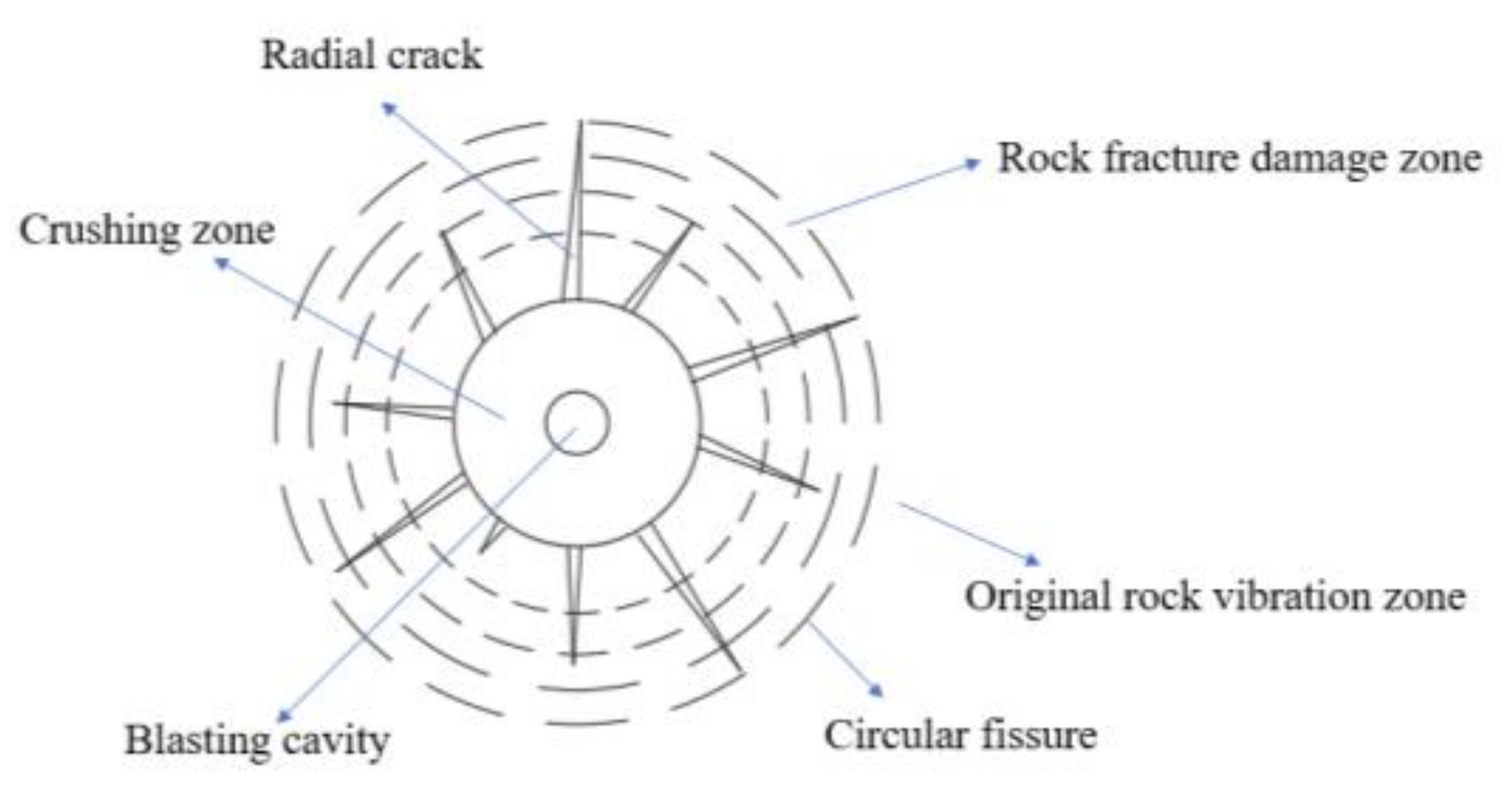
Figure 1. Damage Zoning of Rock Mass under Blasting Load.
Mathematics 09 03242 g001
Figure 2. Blasting effect of trenching field test and UAV 3D scan. (a) Hole layout; (b) Charging device; (c) Field after charge; (e) Blasting pile; (d) Cutting blasting effect; (f) Scanning effect.
Mathematics 09 03242 g002
Figure 3. Scanned area of trenching cross-section at different depths.
Mathematics 09 03242 g003
Figure 4. (a) Schematic diagram of geometric. (b) numerical models and stress application in numerical simulation.
Mathematics 09 03242 g004
Figure 5. Diagram of stress application.
Mathematics 09 03242 g005
Figure 6. The area of the slot cavity under the application of different rock clamping factors, and the rock damage circle is determined by the critical damage parameters obtained above. (a) Kr = 0; (b) Kr = 0.5; (c) Kr = 1.0; (d) Kr = 1.5; (e) Kr = 2.0; (f) Kr = 2.5.
Mathematics 09 03242 g006
Figure 7. Trend of rock damage range and slot cavity area with different rock clamping factor applied.
Mathematics 09 03242 g007
Figure 8. The area of the slot cavity under different stress conditions applied and compared with the field effect. (a) Df = 0 m; (b) Df = 0.5 m; (c) Df = 7.0 m; (d) Df = 10 m.
Mathematics 09 03242 g008
Figure 9. (a) Numerical simulation backpropagation effect compared with field effect; (b) 3 stages of variation of slot cavity area with rock clamping production; (c) The variation pattern of slot cavity area with rock clamping factor and free surface distance.
Mathematics 09 03242 g009
Figure 10. Comparison of actual and regression values.
Mathematics 09 03242 g010
Table 1. Damage Zone of Rock under Blasting Load.
Damage ZoneRock Damage Volume DBlasting Center Distance r/m
Crushing zoneD = 1r < r0
Partition threshold1r0
fracture and damage zoneDcr < D < 1r0 < r < r1
Partition thresholdDcrr1
Primary rock stress zoneDDcrr > r1
Table 2. RHT constitutive parameters.
Constitutive ParametersParameter ValuesAccess Approaches
ρ/kg/m32860testing methods
fc/MPa41.5uniaxial compression test
fs*0.09theoretical calculation
ft*0.02
G/GPa3.8
βc0.028
βt0.033
gc*0.53Constitutive self-contained
gt*0.70
Q00.681
B0.011
D10.04
D21
Table 3. ANN-2 Viscous ammonium nitrate explosive parameters.
Density/kg/m3Detonation Velocity/m/sC-J
Pressure/GPa
Ferocity/mmBlasting Force/mLJWL State Equation Parameters
A/GPaB/GPaR1R2ω
95028006.5182803265.85.801.560.57
Publisher’s Note: MDPI stays neutral with regard to jurisdictional claims in published maps and institutional affiliations.