Article

Entropy Analysis and Melting Heat Transfer in the Carreau Thin Hybrid Nanofluid Film Flow

1
Institute of Mathematical Sciences, Faculty of Science, Universiti Malaya, Kuala Lumpur 50603, Malaysia
2
Center for Data Analytics Consultancy and Services, Faculty of Science, Universiti Malaya, Kuala Lumpur 50603, Malaysia
3
Department of Mathematical Sciences, Faculty of Science & Technology, Universiti Kebangsaan Malaysia, Bangi 43600 UKM, Malaysia
4
Centre for Modelling and Data Analysis (DELTA), Faculty of Science & Technology, Universiti Kebangsaan Malaysia, Bangi 43600 UKM, Malaysia
*
Author to whom correspondence should be addressed.
Mathematics 2021, 9(23), 3092; https://doi.org/10.3390/math9233092
Submission received: 2 November 2021 / Revised: 28 November 2021 / Accepted: 29 November 2021 / Published: 30 November 2021
(This article belongs to the Special Issue Mathematics and Its Applications in Science and Engineering)

Abstract

:
Melting heat transfer has a vital role in forming energy storage devices such as flexible thin film supercapacitors. This idea should be welcomed in the thin film theoretical models to sustain technological advancement, which could later benefit humankind. Hence, the present work endeavors to incorporate the melting heat transfer effect on the Carreau thin hybrid nanofluid film flow over an unsteady accelerating sheet. The mathematical model that obeyed the boundary layer theory has been transformed into a solvable form via an apt similarity transformation. Furthermore, the collocation method, communicated through the MATLAB built-in bvp4c function, solved the model numerically. Non-uniqueness solutions have been identified, and solutions with negative film thickness are unreliable. The melting heat transfer effect lowers the heat transfer rate without affecting the liquid film thickness, while the Carreau hybrid nanofluid contributes more entropy than the Carreau nanofluid in the flow regime.

1. Introduction

The thin film flow research has a great prospect in technological advancement due to its significance in producing electronic devices such as integrated circuits and microscopic fluidic devices [1]. For example, one can see how a solid surface is coated by a thin liquid film in those manufacturing operations. Another potential manufacturing process subset to the thin film flow application is the cast film extrusion that produces polymer sheets and films [2]. Realising the strength of the thin film flow research as an enzyme to attain the next stage of technological development, Wang [3] pioneered the problem of the thin film flow past an accelerating sheet and attested the unavailability of similarity solutions when the flow unsteadiness’ rate exceeds 2. Then, Usha and Sridharan [4] revisited the flow problem in [3] asymmetrically and proved that the similarity solutions are absent when the flow unsteadiness’ rate exceeds 4. As time went by, the researchers learned that heat transfer analysis is crucial in the thin film flow problem, aligned with the initiative to comprehend the heat exchangers and chemical processing equipment’s design. Thus, Andersson et al. [5] solved the thin film flow and heat transfer past an accelerating sheet; they also devised a novel similarity solution for the temperature field. This contribution of [5] is remarkable and highly assists in investigating the heat transfer aspect in the present work. After that, Wang [6] presented the analytic solutions for the thin film flow and heat transfer problem over an unsteady accelerating sheet. The strong contributions of [3,4,5,6] are the impetus for the thin film flow and heat transfer research under the following effects: thermocapilarity [7,8], general surface temperature [9,10], thermal radiation [11], magnetohydrodynamics (MHD) [12], viscous dissipation [13], slip effects [14,15].
The strength of the non-Newtonian fluid in illuminating varying fluid viscosity under the applied force has vast industrial applications and managed to attract the researchers’ attention to be considered under various settings, such as in [16,17]. On the other hand, the researchers’ consideration of the non-Newtonian fluid in the thin film flow problem is raised because the protective coating applied on an extrudate is a non-Newtonian fluid. Therefore, Andersson et al. [18] investigated the power-law thin liquid film flow past an accelerating sheet and found a contradict trend in the fluid velocity when the power-law fluid adapts to the pseudoplastic and dilatant features respectively. Furthermore, Chen [19] enhanced the work of [18] by incorporating the heat transfer characteristic as it is an essential factor to decide the final product’s quality. Subsequently, the researchers’ consideration of other generalised non-Newtonian fluid models such as the Carreau fluid model increased due to its validity for high and low shear rates. Myers [20] critically analysed the generalised non-Newtonian fluid’s potential in the thin film flow and suggested that the Carreau fluid model is a better choice due to its accuracy rate. Accordingly, there is a number of significant works reported within the scope of the Carreau thin film flow; see [21,22,23,24].
Besides that, hybrid nanofluid is an incredible invention by humankind to uplift technological advancement to the next level. Choi and Eastman [25] introduced the brilliant idea of suspending the nanosized metal element in the fluid to boost its heat transfer rate. Although nanofluid hits the peak of the researchers’ interest due to its applications in the heat transfer equipment, nanofluid is incompatible with some specified real-world applications that require substitution between some nanofluids’ properties [26]. Thus, the hybrid nanofluid is proposed to encounter this issue through the experimental works [27,28], and the hybrid nanofluid managed to gain vast interest from the researchers. Shortly, the theoretical works, such as [29] gained momentum in the hybrid nanofluid after the valuable works of Devi and Devi [30,31]. The hybrid nanofluid also succeeded in the thin film flow over an accelerating sheet owing to industrial applications such as microfluidics [32]. For instance, Sadiq et al. [33] explored the Maxwell thin hybrid nanofluid film flow across the Darcy-Forchheimer porous media and inferred that the augmentation of the heat transfer rate in the hybrid Maxwell nanofluid is better than the single-typed Maxwell nanofluid.
Melting heat transfer is a common phase experienced by industrial processes such as casting. Epstein and Cho [34] is one of the earliest works involved in the melting heat transfer effect in the laminar boundary layer flow. Epstein and Cho [34] solved the boundary layer flow problem past the horizontal positioned static flat surface along with the melting heat transfer effect. Ishak et al. [35] extended the work in [29] by considering the flow past the moving sheet and reported that the melting heat transfer effect is the decreasing function of the convective heat transfer rate. Then, Khashi’ie et al. [36] reconsidered the problem solved in [35] by incorporating the presence of hybrid nanoparticles and corroborated the finding as mentioned above in [35]. Even though the melting heat transfer effect has been probed under several settings; see [37,38]; yet, the inspection of the melting heat transfer effect in the thin film flow is scarce. Thus, this motivates the present work to scruntise the melting heat transfer effect in the thin film flow.
Overall, the present work attempts to solve the problem of the Carreau thin hybrid nanofluid film flow past an accelerating sheet under the influence of the melting heat transfer. The present model is relatively new, and entropy generation analysis is performed. The present work also adapts the similarity transformation suggested by Andersson et al. [5], and the formulated mathematical model has been solved in the built-in collocation method, the bvp4c, to produce the approximate solutions. Furthermore, non-uniqueness solutions have been reported for every case of governing parameters’ variations. The findings of the present work may serve as a reference for improving the material processing industry.

2. Mathematical Model

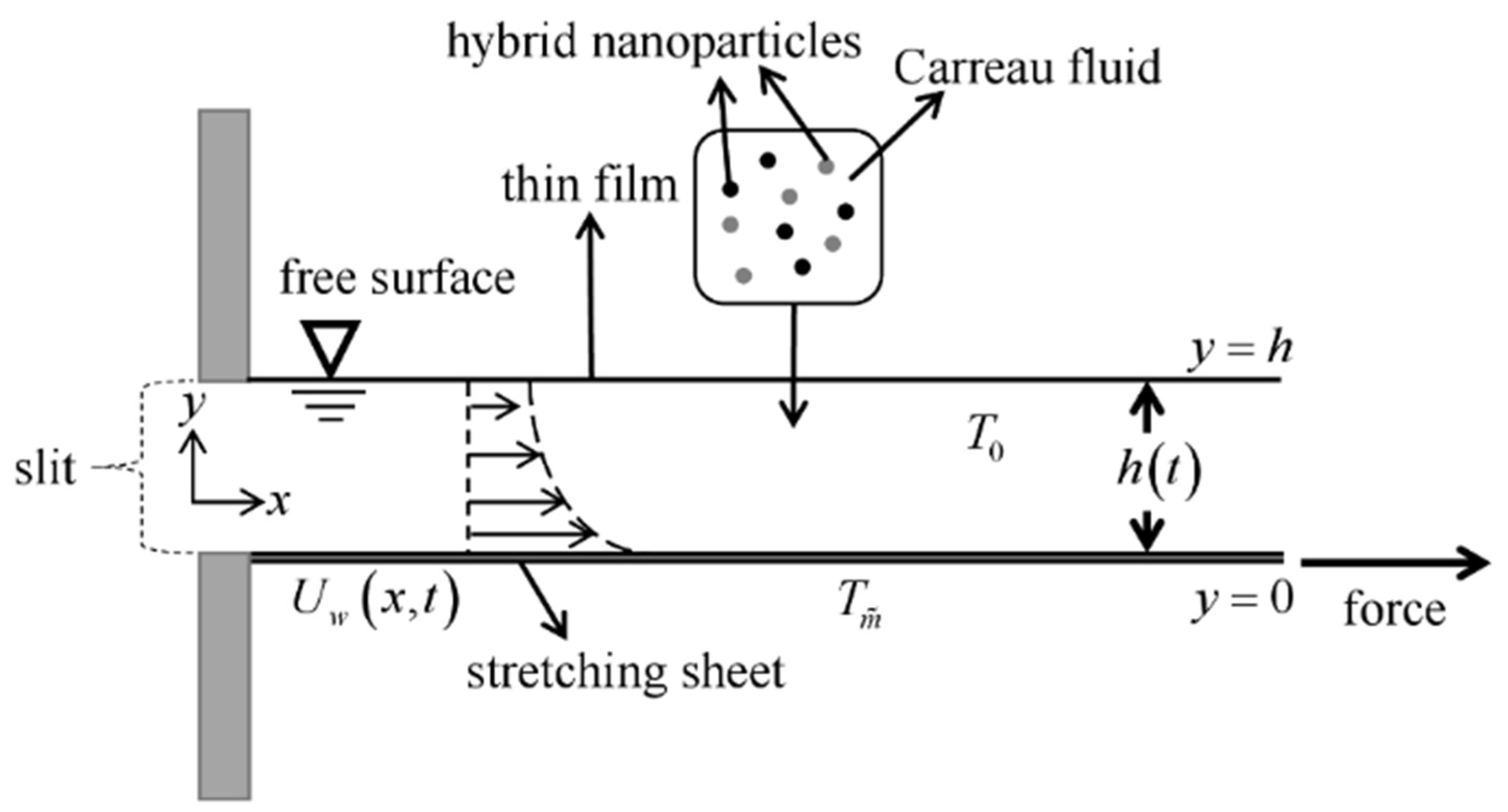
Ruminate the Carreau fluid flow bounded by a thin liquid film and a horizontally placed accelerating sheet from a narrow opening at the Cartesian coordinate system origin. The two-dimensional flow is assumed to be incompressible, unsteady while the thin liquid film has an unvarying thickness, H ( t ) .  Figure 1 depicts the flow setup, and y coordinate is located normal to the x coordinate. The sheet’s accelerated act, which portrays the stretching sheet situation, brings about the fluid motion delimited by the thin film and the accelerating sheet. The sheet is accelerated with speed U w ( x , t ) = b x ( 1 σ t ) , where b and σ are positive constants with dimension time–1, σ t 1 , while b > 0 conveys the stretching rate. The sheet surface is impermeable and melts. The melting surface temperature is denoted by T m ˜ , whereas T is the fluid temperature. The wall temperature, T w is defined as T w = T s T 0 b 2 x 4 4 ν f 2 ( 1 σ t ) , and 0 T 0 T s [39]. Here, the slit temperature and reference temperature are denoted by T s and T 0 , respectively. Besides, the end effects and gravity are assumed to be very small and thus omitted. The formulated boundary layer model in the present work is only sensible if the liquid film thickness does not overlap with the boundary layer thickness. Otherwise, the present formulated model becomes irrational [40]. Also, the planar thin liquid film is assumed to be smooth and free of any surface waves [5].
The Carreau fluid’s Cauchy stress tensor is given as [20]
τ = p I + η A 1 ,
where
η = η + ( η 0 η ) [ 1 + ( λ γ ˙ ) 2 ] n 1 2 .
Here, τ is the Cauchy stress tensor, p is the pressure, I denotes the identity tensor, η 0 signifies the zero-shear-rate viscosity, η is the infinite-shear-rate viscosity, λ implies the material time constant, and n represents the power-law index. The shear rate, γ ˙ can be elaborated as
γ ˙ = 1 2 ( γ ˙ : γ ˙ ) = 1 2 Π = 1 2 t r ( A 1 2 ) = 1 2 i j γ ˙ i j γ ˙ j i .
In Equation (3), Π is the second invariant strain rate tensor and A 1 is the Rivlin-Ericksen tensor expressed further as
A 1 = ( grad V ) + ( grad V ) Τ .
The most practical cases where η 0 η is considered. Normally, the value of η is determined by the extrapolation procedure or chosen to be zero (suggested theoretical value) [41]. Thus, in the present work, the value of η is set to zero, and affect Equation (1) to become
τ = p I + η 0 [ 1 + ( λ γ ˙ ) 2 ] n 1 2 A 1 .
The Carreau fluid model shows pseudoplastic, dilatant, and Newtonian features when 0 < n < 1 , n > 1 and n = 0 , respectively, where n is the power-law index. Under these assumptions, the governing liquid film flow of the Carreau fluid can be written as [42].
u x + v y = 0 ,
u t + u u x + v u y = μ h n f ρ h n f 2 u y 2 [ 1 + λ 2 ( u y ) 2 ] n 1 2 + μ h n f ρ h n f ( n 1 ) λ 2 2 u y 2 ( u y ) 2 [ 1 + λ 2 ( u y ) 2 ] n 3 2 ,
T t + u T x + v T y = k h n f ( ρ C p ) h n f 2 T y 2 ,
where u and v are the velocity components along the x - and y - directions, respectively, λ is a material time constant, n signifies the power-law index. Meanwhile, ( ρ C p ) h n f , μ h n f , ρ h n f , and k h n f are the hybrid nanofluid’s heat capacity, dynamic viscosity, density and thermal conductivity, respectively. The further definition of μ h n f , ρ h n f , k h n f , and ( ρ C p ) h n f are expressed in Table 1.
According to Table 1, the nanoparticle volume fraction is ϕ and ϕ = 0 reduces the model into a regular fluid. Next, ϕ 1 and ϕ 2 signify the Au’s and Cu’s nanoparticle volume fraction, respectively. The total volume concentration of two types of nanoparticles suspended in the hybrid nanofluid is determined as ϕ h n f = ϕ 1 + ϕ 2 . Meanwhile, ρ f and ρ h n f are the densities of the base fluid and the hybrid nanoparticle, respectively, k f and k h n f are the thermal conductivities of the base fluid and the hybrid nanoparticles, respectively, ( ρ C p ) f and ( ρ C p ) h n f are the heat capacitance of the base fluid and the hybrid nanoparticle, respectively. These correlations are based on physical assumptions and agree with the conservation of mass and energy. Thus, the physical properties of the base fluid (water), gold (Au) and copper (Cu) hybrid nanofluids are given in Table 2.
The Equations (6)–(8) are getting along with the boundary conditions
t < 0 : u = 0 , v = 0 , T = T y = 0 for all   x   and   y . t 0 : u = U w ( x , t ) , k h n f ρ h n f ( T y ) y = 0 = [ L + ( C p ) s ( T m ˜ T s ) ] v ( x , t ) , T = T m ˜ at y = 0 , u y = 0 , T y = 0 , v = d h d t at y = h ,
At y = h , the kinematic constraint is enforced in the fluid motion through v = d h / d t . The wall shear stress and heat flux disappear entirely at the adiabatic free surface and thus u / y = T / y = 0 at y = h . Next, we introduce the similarity transformations as follows (Andersson et al. [5]):
ψ = x f ( ζ ) ν f b 1 σ t , u = ψ y = b x 1 σ t f ( ζ ) , v = ψ x = ν f b 1 σ t f ( ζ ) , θ ( ζ ) = T T m ˜ T 0 T m ˜ , T = T s T 0 ( b x 2 2 ν f ) 1 ( 1 σ t ) 3 θ ( ζ ) ,
ζ = y b ν f ( 1 σ t ) ,
where prime infers the derivative concerning ζ . Employing the similarity conversion as in (10) and (11) into the governing model (6)–(9) satisfies the continuity equation, and the remaining equations are transformed as follows:
( μ h n f / μ f ρ h n f / ρ f ) ( 1 + n W e 2 f 2 ) ( 1 + W e 2 f 2 ) n 3 2 f + ( f f ω ζ 2 f f 2 ω f ) = 0 ,
k h n f / k f ( ρ C p ) h n f / ( ρ C p ) f θ + Pr ( f θ 2 f θ ζ ω 2 θ 3 ω 2 θ ) = 0 ,
with the boundary conditions
Pr f ( 0 ) + k h n f / k f ρ h n f / ρ f χ θ ( 0 ) = 0 , f ( 0 ) = 1 , f ( β ) = ω β / 2 , f ( β ) = 0 , θ ( 0 ) = 0 , θ ( β ) = 0 ,
wherein W e = λ 2 b 3 x 2 ν f ( 1 σ t ) 3 , is the local Weissenberg number [46], ω = σ b is the dimensionless measure of unsteadiness, the Prandtl number is defined as Pr = ( C p ) f μ f k f , while the melting heat transfer parameter is signified by χ = ( C p ) f ( T 0 T m ˜ ) L + ( C p ) s ( T m ˜ T s ) . Moreover, β is an unknown constant that conveying the dimensionless film thickness. β also implies the similarity variable ( ζ ) value at the free surface, and hence the expression in (11) can take the following form:
β = h b ν f ( 1 σ t ) ,
This unknown constant β must be calculated as an integral part of the boundary-value problem. Thus,
d h d t = β σ 2 ν f ν f ( 1 σ t ) ,
elucidates the film thickness’s rate of change. On the other hand, when n = 1 and W e = 0 , the Carreau fluid model in Equations (12) and (13) reveals the Newtonian characteristics. The physical quantities of interest in the present work are the local skin friction coefficient ( C f x ) and the local Nusselt number ( N u x ) , which can be defined as follows:
C f x = τ w ρ f ( U w ) 2 / 2 , N u x = q w x k f T 0 ,
Here, the wall shear stress ( τ w ) and the heat flux from the surface of the sheet ( q w ) are given by [47].
τ w = { μ h n f u y [ 1 + λ 2 ( u y ) 2 ] n 1 2 } y = 0 , q w = k h n f ( T y ) | y = 0 ,
By employing (10)–(11) and inducing (19) into (18) provides the following expression.
C f x Re x 1 / 2 = μ h n f μ f 2 f ( 0 ) { 1 + W e 2 [ f ( 0 ) ] 2 } n 1 2 , 2 N u x Re x 3 / 2 ( 1 α t ) 1 / 2 k f k h n f = θ ( 0 ) .
The local Reynolds number is defined as Re x = x U w ( x , t ) ν f .

3. Entropy Analysis

The entropy generation analysis is ideal for calculating the dissipated heat energy and measuring any flow systems’ performance deterioration. This nonconserved property can be communicated in the following dimensional form [48]:
S g e n = k h n f T 0 2 ( T y ) 2 + μ h n f T 0 [ 1 + λ 2 ( u y ) 2 ] n 1 2 ( u y ) 2 ,
where terms on heat irreversibility is given followed by the fluid friction irreversibility. By using Equations (10) and (11) into (20), the nondimensional form of the volumetric entropy generation can be formed as follows:
N s = k h n f k f θ 2 ( ζ ) + μ h n f μ f B r ε f 2 ( ζ ) ,
Here, the local entropy generation rate ( N s ) , the Brinkman number ( B r ) , and the temperature difference parameter ( ε ) are further defined as follows:
N s = S g e n T 0 2 ( 1 σ t ) ν f b k f ( T 0 T m ˜ ) 2 , B r = μ f b 2 x 2 k f ( 1 σ t ) 2 ( T 0 T m ˜ ) , ε = T 0 T 0 T m ˜ .
In the entropy generation analysis, it is necessary to compute the Bejan number to identify which entropy generation appears to dominate the flow system, either frictional or thermal entropy generation. Thus, the Bejan number is calculated in the present work, and it takes the following form:
B e = ( k h n f k f θ 2 ( ζ ) ) ( k h n f k f θ 2 ( ζ ) + μ h n f μ f B r ε f 2 ( ζ ) ) = 1 1 + Φ ,
where Φ = ( μ h n f μ f B r ε f 2 ( ζ ) ) ( k h n f k f θ 2 ( ζ ) ) is the irreversibility ratio. Expression in (23) signifies the heat transfer irreversibility and total entropy ratio in the flow system. Contact melting, lubrication, and electronic cooling are some heat transfer applications where the Bejan number is vital. Equation (23) also can be utilised to determine the following effects in the flow system (see Table 3):

4. Results and Discussion

The transport phenomena in the thin film flow regime can be learned by plotting the velocity and temperature profiles. In addition, calculating the local skin friction coefficient, the local Nusselt number and the dimensionless film thickness when the pertinent parameters vary is also necessary to inspect the present model’s performance. Thus, all numerical outputs were generated by setting the governing parameters’ values within the following fixed range: 0 W e 0.3 , 0 χ 2.5 , 0.8 ω 1.4 , and 0.6 n 1.6 . The Prandtl number is fixed to 8 throughout the computation process. Also, ϕ 1 and ϕ 2 represents the gold (Au) and copper (Cu) nanoparticle volume fractions, respectively. The numerical outputs are compared between the Carreau hybrid nanofluid case, where ϕ 1 = 0.02 , ϕ 2 = 0.03 , and the single-typed Carreau nanofluid is considered with ϕ 1 = 0 , ϕ 2 = 0.03 . These parameter values are chosen based on the availability of the numerical solutions. However, those parameter values lie within the acceptable range established in previously published works. Equations (12)–(14), which convey the simplified form of the present thin film flow problem, are solved using the bvp4c function found in the MATLAB 2019a software. This built-in collocation code eases the solving process even though the present work has dimensionless film thickness as the unknown parameter [50]. Besides that, all computed numerical results are accurate within 1 × 10 10 . In order to test the precision of the present method, the thin film flow problem studied by Wang [6] have been resolved via the bvp4c function, and the comparison of the results is given in Table 4. Table 4 proves that the built-in collocation method agrees well with the numerical results produced via the homotopy analysis method in [6]. Meanwhile, the CPU time for calculating the non-uniqueness solutions is presented in Table 5. In this sample, it is apparent that the CPU time increases from the first to the second solution in every case of n. Before the presentation and discussion of the results go further, it is appropriate to confer about the non-uniqueness numerical solutions. It is undeniable that more than one numerical solutions are obtainable by providing a good set of guess values since that is the built-in bvp4c routine’s requirement. The present work found that the second solutions always yield negative film thickness. The negative film thickness implies the thin liquid film’s distortion, and hence an ideal thin liquid film cannot be formed [23]. Therefore, the trends showed by the second solution are disregarded.
Now, 
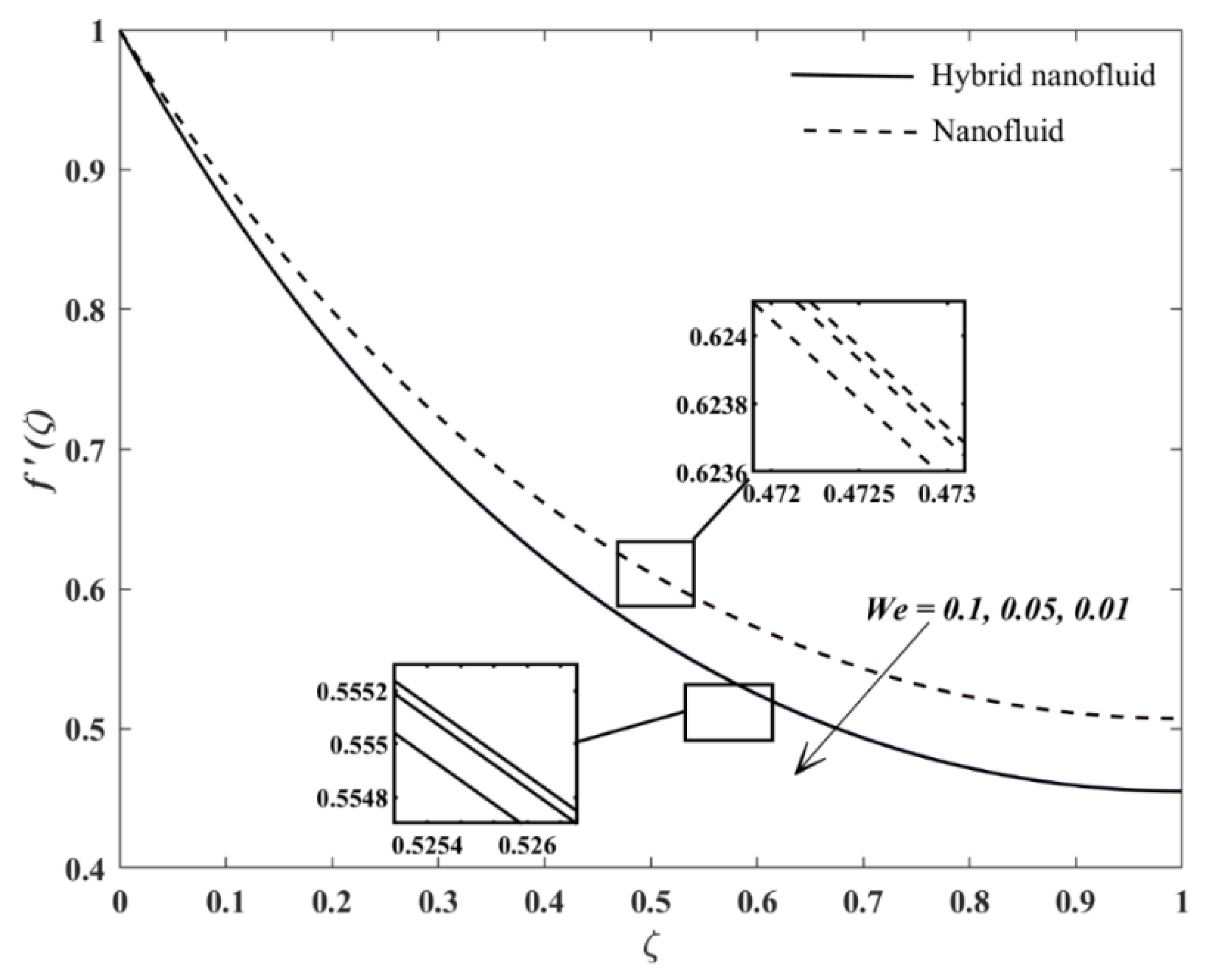
Table 6 demonstrates the trend of β for the Carreau hybrid nanofluid and Carreau nanofluid when W e increases. The increment of W e from 0 to 0.3 affects the dimensionless film thickness to decrease by 0.25% for Carreau hybrid nanofluid and decrement by 0.18% for the Carreau nanofluid. The reason for this occurrence can be collected from Figure 2 and Table 7. Figure 2 shows that the fluid velocity increases insignificantly across the flow regime when W e increases. The increment in W e elucidates a longer relaxation rate; thus, the Carreau fluid takes more time to react with the external forces. Since the accelerating sheet imposes drag force towards the Carreau fluid (this can be evident by the negative values of C f x Re x 1 / 2 in Table 7), the fluid velocity increases slightly past the unsteady accelerating sheet, which elevates the wall shear stress and increases the values of C f x Re x 1 / 2 in a minimal amount.
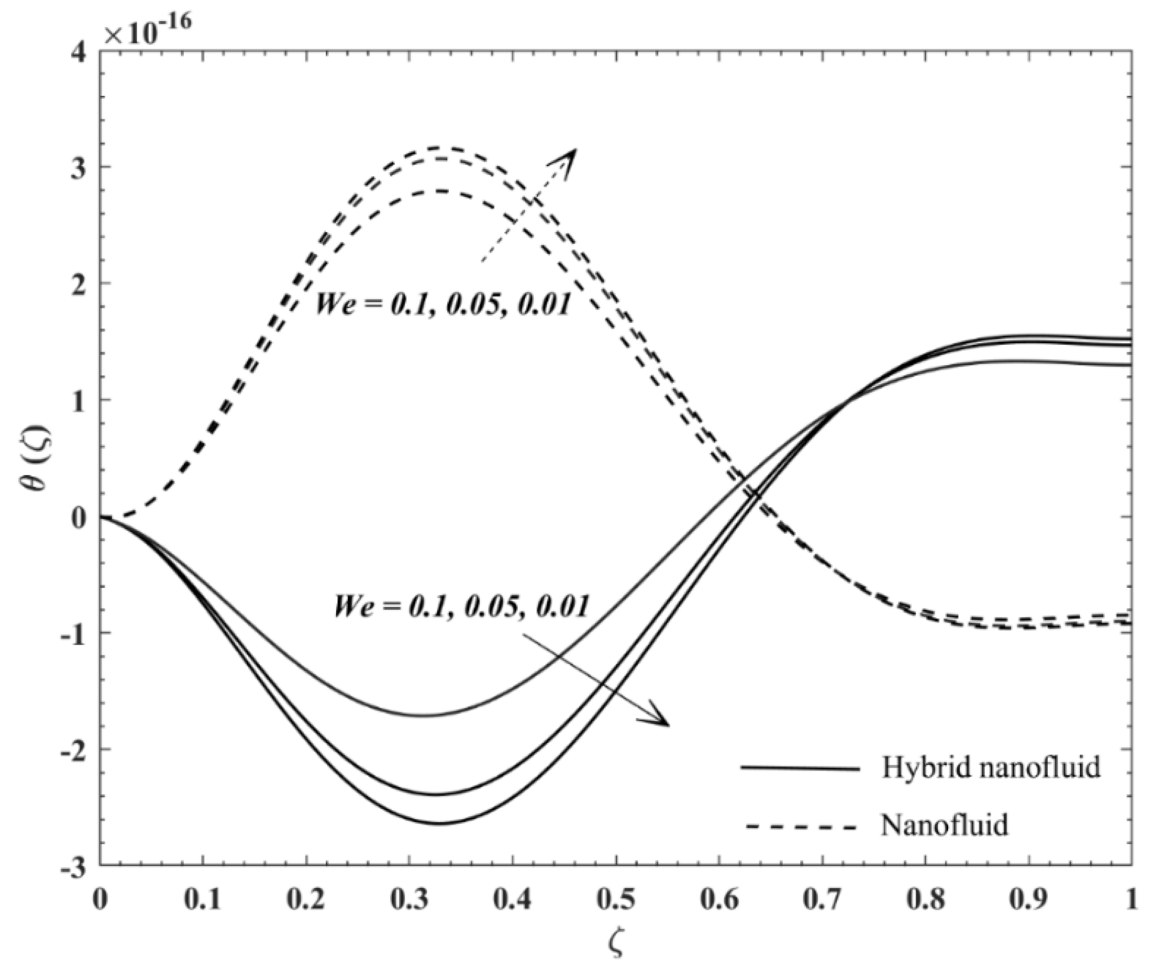
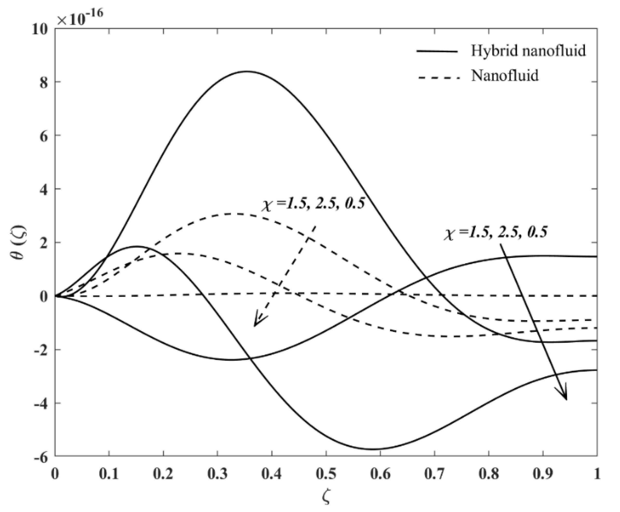
Meanwhile, Figure 3 displays the temperature profiles across the thin film flow vicinity. For the Carreau fluid associated with the hybrid nanoparticles, the temperature increases when W e increases. This behavior is evident when 0 ζ < 0.72727 . It should be noted that the fluid is under the influence of shear thinning effect ( n = 0.8 ) , and hence the fluid viscosity may decrease with the act of the accelerating sheet and the melting heat transfer’s effect. At this moment, when the effect of W e is amplified, the fluid temperature augments since the relaxation time is prolonged. A similar result has been reported by Hayat et al. [51]. However, after ζ = 0.72727 , the fluid far from the accelerating surface is less affected with the melting heat transfer and thus, the fluid temperature decreases when W e increases. On the other hand, in the case of the Carreau nanofluid, fluid temperature increases with declining values of W e when 0 ζ < 0.72727 , and the opposite trend is observed after ζ = 0.72727 . Such an interesting difference in the trend might be due to the suspended nanoparticles’ thermal conductivity in the base fluid. Besides that, Table 8 tabulates changes in the heat transfer rate at the accelerating impermeable surface. The flow with the copper nanoparticles spectacle a gradual increase in θ ( 0 ) , and this is acceptable because copper has better thermal conductivity and results in an increased rate in heat exchange. However, the hybrid nanofluid does not exhibit a gradual degree of improvement. The heat transfer rate decreases when W e ’s value increases from 0 to 0.3. The increment in the fluid relaxation time affects the Carreau hybrid nanofluid to become warm, which lowers heat flux from the accelerating surface and diminishes θ ( 0 ) .
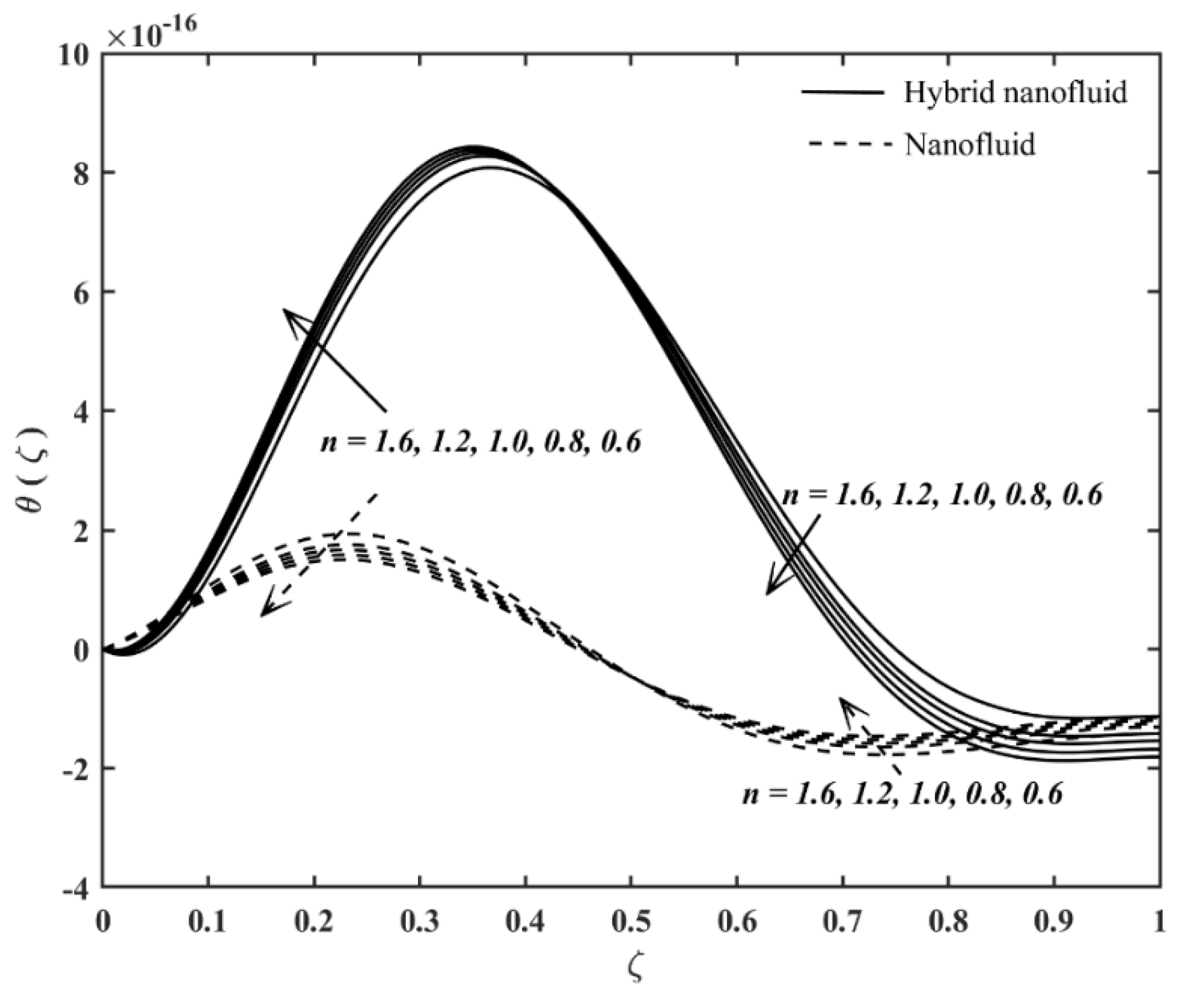
The results’ discussion is further by examining the behavior of the temperature profiles and θ ( 0 ) when χ increases. Even though the temperature profiles in Figure 4 reveal an unusual degree of dissonance, Table 9 informs that the convective heat transfer rate at the accelerating sheet increases in the single-typed nanofluid but deteriorates in the Carreau fluid with hybrid suspensions. The increment in χ indicates more cold fluid molecules exist from the melting accelerating sheet towards the warm fluid. Therefore, the nanofluid temperature declines at the moving surface and augments the heat exchange rate. The work of Khan et al. [52] also conveyed such similar result. Conversely, the hybrid nanofluid temperature may have retained a low thermal conductivity, ensuring the low heat flux rate and reducing θ ( 0 ) at the accelerating surface. Table 10 confirms that when the Carreau fluid with the presence of the nanoparticles changes its character from the shear thinning to the shear thickening feature, the dimensionless film thickness slightly increases, in increments of about 0.035% and 0.025% for the Carreau hybrid nanofluid and Carreau single-typed nanofluid, respectively.
Meanwhile, the temperature profiles in Figure 5 display that when ζ 0.444 , the Carreau hybrid nanofluid temperature decreases while n increases from 0.6 to 1.6. This is because the dilatant feature retards the heat energy transmission. However, when the liquid film vicinity travel at ζ > 0.444 , the fluid temperature becomes an increasing function of n . The area far from the accelerating sheet is possibly less affected by the shear force from the accelerating sheet, so heat transmission is reduced. Also, from Figure 5, it is observed that the fluid temperature is low at the area far from the accelerating sheet compared to the fluid temperature near the sheet’s surface. Table 11 identifies that the heat transfer rate at the accelerating sheet gradually decreases for the Carreau hybrid nanofluid when n increases. This is true because Metzner et al. [53] corroborated that dilatant fluid has a lower heat transfer rate than the shear-thinning fluid. On the other hand, the opposite trend is perceived for the single-typed hybrid nanofluid. In the single-typed nanofluid considered in the present work, the nanoparticle volume fraction is less than the hybrid nanofluid, which may increase the fluid’s thermal conductivity as the low-temperature molecules enter the flow stream. Thus, a moderate increase in θ ( 0 ) ’s values can be noticed along with the increment of n .  Table 12 delivers the decrement of C f x Re x 1 / 2 along with the increment of n . The strengthening effect of n reduces the wall shear stress at the accelerating sheet. Hence, the values of C f x Re x 1 / 2 decline.
Figure 6, Figure 7, Figure 8 and 
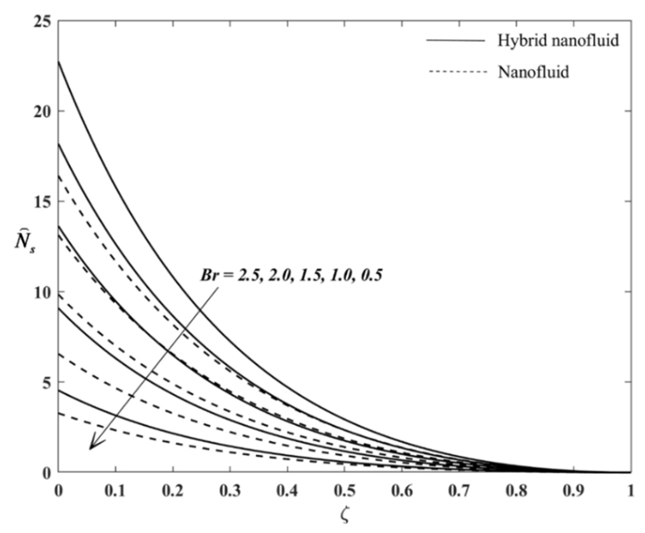
Figure 9 show the results of the entropy generation analysis. Figure 6 views the increment in N s when B r increases. Adding value in B r engenders more heat in the fluid flow vicinity, affecting the system more in chaos and resulting in undesirable flow systems’ performance. Moreover, 
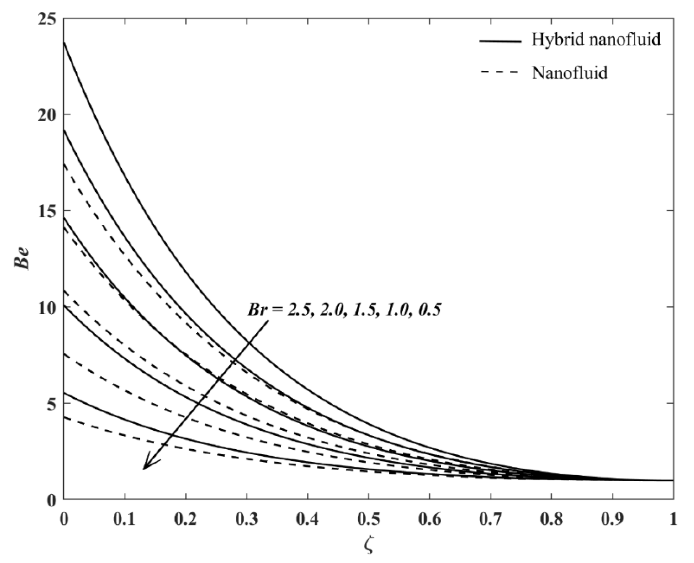
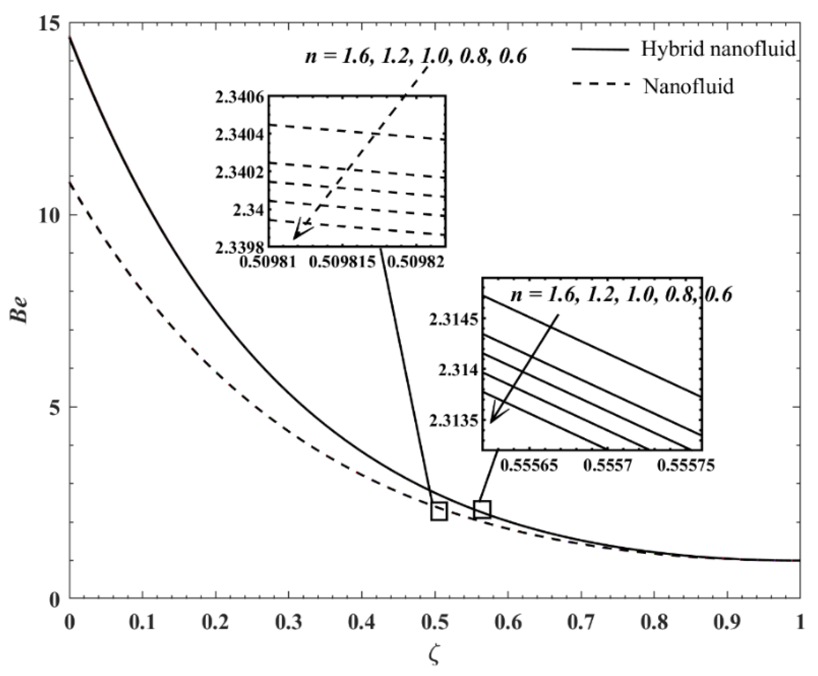
Figure 7 exposes the Bejan number profiles when B r varies, and the values of B e increases along with the increment in B r . It is clear that the heat transfer irreversibility is gradually influencing throughout the flow system when B r rises, except for the case of the Carreau single-typed nanofluid, and B r = 0.5 . Figure 7 indicates that when Carreau nanofluid at B r = 0.5 , fluid friction irreversibility dominates the flow system.
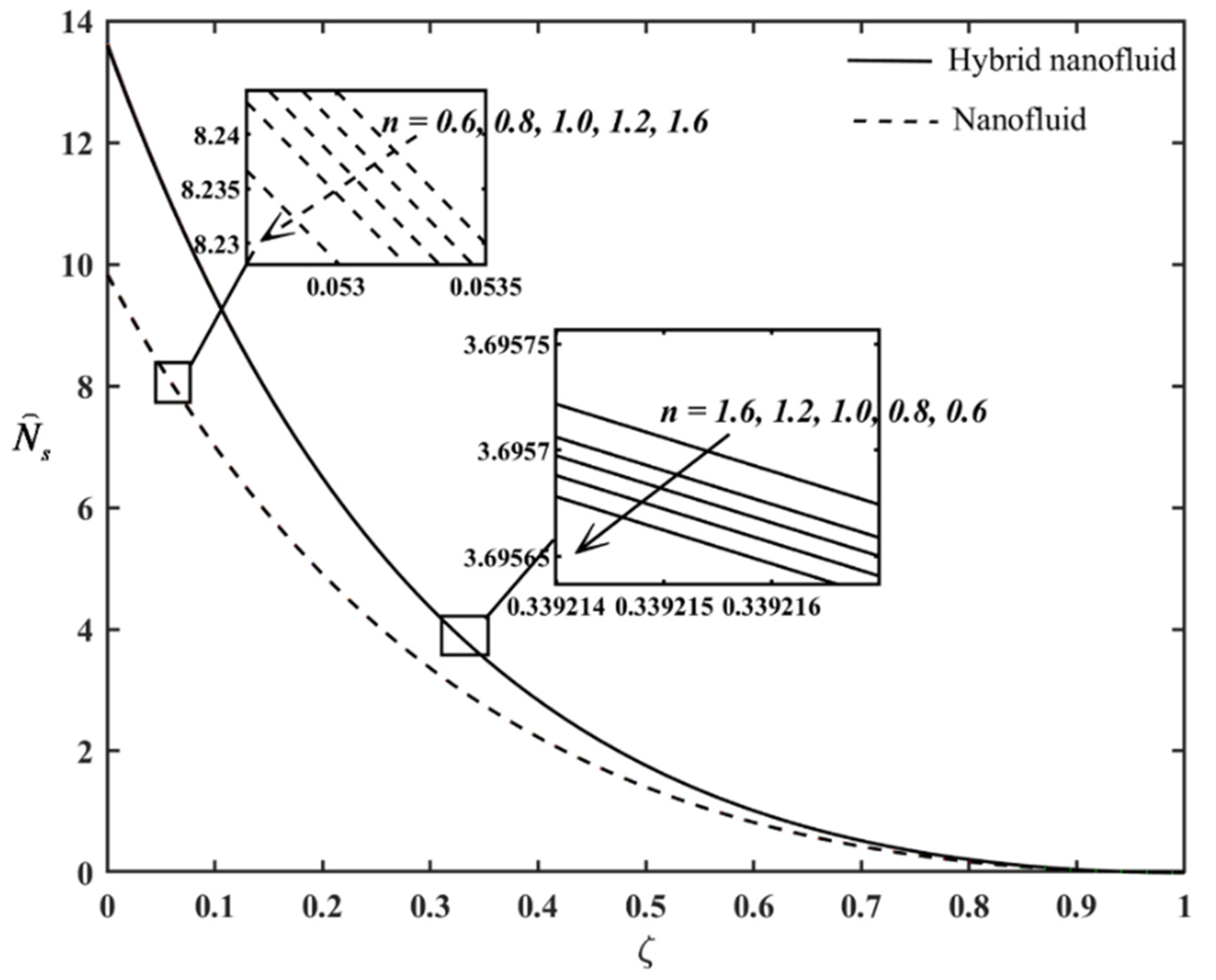
 Figure 8 and Figure 9 present the profiles of N s and B e profiles when n varies. The variation in n gives insignificant changes on N s and B e profiles. For example, from Figure 8, the state of the Carreau fluid from portraying the shear-thinning trait and then to the shear-thickening feature yields more heat energy incorporated to the system but minimal. However, the heat transfer irreversibility highly influences the fluid flow system, although Figure 9 shows the minor decrement in B e when the values of n increases.

5. Conclusions

The present work endeavored to investigate the performance of the Carreau thin hybrid nanofluid film flow and heat transfer while the melting heat transfer effect imposed on the accelerating sheet. Interestingly, this is the original work in the thin film Carreau hybrid nanofluid theoretical model, considering the impact of the melting heat transfer. Two approximate solutions were identified for every variation case. The Carreau hybrid nanofluid’s heat transfer rate decreases when the fluid adapts to the dilatant feature. Besides that, the presence of the hybrid nanoparticles promotes entropy in the flow system compared to the mono-typed nanoparticles. The numerical solutions with negative film thickness indicated defective thin film flow and unreliable. However, the melting heat transfer effect does not affect the liquid film thickness.

Author Contributions

Conceptualisation, K.N. and I.H.; methodology, K.N.; software, K.N.; validation, I.H., R.N. and Z.S.; formal analysis, K.N.; investigation, K.N., R.N., I.H., and Z.S.; writing—original draft preparation, K.N.; writing—review and editing, K.N., I.H., R.N., and Z.S.; funding acquisition, R.N. All authors have read and agreed to the published version of the manuscript.

Funding

This research and APC was funded by Ministry of Higher Education, Malaysia, grant number FRGS/1/2020/STG06/UKM/01/1.

Institutional Review Board Statement

Not applicable.

Informed Consent Statement

Not applicable.

Data Availability Statement

Data sharing not applicable.

Conflicts of Interest

The authors declare no conflict of interest.

Nomenclature

A 1 first Rivlin-Ericksen tensor (Pa)
Augold
b stretching rate ( s 1 )
BeBejan number ( )
C f x local skin friction coefficient ( )
C p specific heat at constant pressure ( Jkg 1 K 1 )
Cucopper
f ( ζ ) dimensionless stream function ( )
H ( t ) liquid thin film thickness ( m )
I identity tensor ( )
k f fluid’s thermal conductivity ( Wm 1 K 1 )
k h n f hybrid nanofluid’s thermal conductivity ( Wm 1 K 1 )
L fluid’s latent heat ( J / kg )
n power-law index ( )
N s local entropy generation rate
N u x local Nusselt number ( )
p pressure (Pa)
Pr Prandtl number ( )
q w wall heat flux ( Js 1 m 2 )
Re x local Reynolds number ( )
T temperature ( K )
T s temperature at slit ( K )
T w wall temperature ( K )
T 0 reference temperature ( K )
T m ˜ melting surface temperature ( K )
t time ( s )
u , v velocity components at x and y axes ( ms 1 )
U w ( x , t ) accelerating sheet’s velocity ( ms 1 )
V velocity fields ( ms 1 )
W e local Weissenberg number ( )
x , y Cartesian coordinates (m)
Greek Symbols
Π second invariant strain rate tensor (Pa)
β unknown parameter ( )
γ ˙ shear rate ( s )
ω unsteadiness parameter ( )
ζ similarity variable ( )
η apparent viscosity ( kg m 1 s 1 )
η high shear rates viscosity ( kg m 1 s 1 )
η 0 zero shear rates viscosity ( kg m 1 s 1 )
θ non-dimensional temperature ( )
λ material time constant (s)
μ h n f hybrid nanofluid’s dynamic viscosity ( kg m 1 s 1 )
μ f fluid’s dynamic viscosity ( kg m 1 s 1 )
ν f base fluid’s kinematic viscosity ( m 2 s 1 )
ρ h n f hybrid nanofluid’s density ( kg m 3 )
σ positive constant ( s 1 )
τ Cauchy stress tensor (Pa)
τ w wall shear stress ( kgm 1 s 2 )
ϕ 1 Au’s nanoparticle volume fraction ( )
ϕ 2 Cu’s nanoparticle volume fraction ( )
ψ stream function ( )
χ melting heat transfer parameter ( )
Subscripts
w condition at the stretching sheet’s wall
f base fluid
n f nanofluid
h n f hybrid nanofluid
s 1 Au’s solid component
s 2 Cu’s solid component
Superscript
' derivative with respect to ζ

References

  1. Diez, J.A.; Kondic, L. Computing three-dimensional thin film flows including contact lines. J. Comput. Phys. 2002, 183, 274–306. [Google Scholar] [CrossRef] [Green Version]
  2. Cotto, D.; Duffo, P.; Haudin, J.M. Cast film extrusion of polypropylene films. Int. Polym. Proc. 1989, 4, 103–113. [Google Scholar] [CrossRef]
  3. Wang, C.Y. Liquid film on an unsteady stretching surface. Q. Appl. Math. 1990, 48, 601–610. [Google Scholar] [CrossRef] [Green Version]
  4. Usha, R.; Sridharan, R. The axisymmetric motion of a liquid film on an unsteady stretching surface. J. Fluids Eng. 1995, 117, 81–85. [Google Scholar] [CrossRef]
  5. Andersson, H.I.; Aarseth, J.B.; Dandapat, B.S. Heat transfer in a liquid film on an unsteady stretching surface. Int. J. Heat Mass Transf. 2000, 43, 69–74. [Google Scholar] [CrossRef]
  6. Wang, C. Analytic solutions for a liquid film on an unsteady stretching surface. Heat Mass Transf. 2006, 42, 759–766. [Google Scholar] [CrossRef]
  7. Dandapat, B.S.; Santra, B.; Vajravelu, K. The effects of variable fluid properties and thermocapillarity on the flow of a thin film on an unsteady stretching sheet. Int. J. Heat Mass Transf. 2007, 50, 991–996. [Google Scholar] [CrossRef]
  8. Noor, N.F.M.; Hashim, I.H. Thermocapillarity and magnetic field effects in a thin liquid film on an unsteady stretching surface. Int. J. Heat Mass Transf. 2010, 53, 2044–2051. [Google Scholar] [CrossRef]
  9. Noor, N.F.M.; Abdulaziz, O.; Hashim, I. MHD flow and heat transfer in a thin liquid film on an unsteady stretching sheet by the homotopy analysis method. Int. J. Numer. Meth. Fluids 2010, 63, 357–373. [Google Scholar] [CrossRef]
  10. Aziz, R.C.; Hashim, I.; Alomari, A.K. Thin film flow and heat transfer on an unsteady stretching sheet with internal heating. Meccanica 2011, 46, 349–357. [Google Scholar] [CrossRef]
  11. Aziz, R.C.; Hashim, I.; Abbasbandy, S. Effects of thermocapillarity and thermal radiation on flow and heat transfer in a thin liquid film on an unsteady stretching sheet. Math. Probl. Eng. 2012, 2012, 127320. [Google Scholar] [CrossRef] [Green Version]
  12. Alam, M.K.; Siddiqui, A.M.; Rahim, M.T.; Islam, S. Thin-film flow of magnetohydrodynamic (MHD) Johnson-Segalman fluid on vertical surfaces using the Adomian decomposition method. Appl. Math. Comput. 2012, 219, 3956–3974. [Google Scholar] [CrossRef]
  13. Rehman, A.; Salleh, Z.; Gul, T.; Zaheer, Z. The impact of viscous dissipation on the thin film unsteady flow of GO-EG/GO-W nanofluids. Mathematics 2019, 7, 653. [Google Scholar] [CrossRef] [Green Version]
  14. Yusuf, T.A.; Kumar, R.N.; Prasannakumara, B.C.; Adesanya, S.O. Irreversibility analysis in micropolar fluid film along an incline porous substrate with slip effects. Int. Commun. Heat Mass Transf. 2021, 126, 105357. [Google Scholar] [CrossRef]
  15. Aslani, K.E.; Mahabaleshwar, U.S.; Sakanaka, P.H.; Sarris, I.E. Effect of partial slip and radiation on liquid film fluid flow over an unsteady porous stretching sheet with viscous dissipation and heat source/sink. J. Porous Media 2021, 24, 1–15. [Google Scholar] [CrossRef]
  16. Aslani, K.E.; Sarris, I.E. Effect of micromagnetorotation on magnetohydrodynamics Poiseuille micropolar flow: Analytical solutions and stability analysis. J. Fluid Mech. 2021, 920, A25. [Google Scholar] [CrossRef]
  17. Madhukesh, J.K.; Alhadhrami, A.; Kumar, R.N.; Gowda, R.J.P.; Prasannakumara, B.C.; Kumar, R.S.V. Physical insights into the heat and mass transfer in Casson hybrid nanofluid flow induced by a Riga plate with thermophoretic particle deposition. Proc. Inst. Mech. Eng. E: J. Process Mech. Eng. 2021. [Google Scholar] [CrossRef]
  18. Andersson, H.I.; Aarseth, J.B.; Braud, N.; Dandapat, B.S. Flow of a power-law fluid film on an unsteady stretching surface. J. Non-Newton. Fluid Mech. 1996, 62, 1–8. [Google Scholar] [CrossRef]
  19. Chen, C.H. Heat transfer in a power-law fluid film over a unsteady stretching sheet. Heat Mass Transf. 2003, 39, 791–796. [Google Scholar] [CrossRef]
  20. Myers, T.G. Application of non-Newtonian models to thin film flow. Phys. Rev. E 2005, 72, 066302. [Google Scholar] [CrossRef]
  21. Sulochana, C.; Ashwinkumar, G.P. Carreau model for liquid thin film flow of dissipative magnetic-nanofluids over a stretching sheet. Int. J. Hybrid Inf. Technol. 2017, 10, 239–254. [Google Scholar] [CrossRef]
  22. Sulochana, C.; Ashwinkumar, G.P. Numerical solution of heat transfer characteristics in thin film flow of MHD dissipative Carreau nanofluid past a stretching sheet with CoFe2O4 nanoparticles. Int. J. Res. Eng. Technol. 2016, 5, 18–25. [Google Scholar]
  23. Naganthran, K.; Hashim, I.H.; Nazar, R. Non-uniqueness solutions for the thin Carreau film flow and heat transfer over an unsteady stretching sheet. Int. Commun. Heat Mass Transf. 2020, 117, 104776. [Google Scholar] [CrossRef]
  24. Naganthran, K.; Hashim, I.H.; Nazar, R. Triple solutions of Carreau thin film flow with thermocapillarity and injection on an unsteady stretching sheet. Energies. 2020, 13, 3177. [Google Scholar] [CrossRef]
  25. Choi, S.U.S.; Eastman, J. Enhancing thermal conductivity of fluids with nanoparticles. ASME Publ. Fed. 1995, 231, 99–103. [Google Scholar]
  26. Babu, J.A.R.; Kumar, K.K.; Rao, S.S. State-of-art review on hybrid nanofluids. Renew. Sust. Energ. Rev. 2017, 77, 551–565. [Google Scholar] [CrossRef]
  27. Suresh, S.; Venkitaraj, K.P.; Selvakumar, P.; Chandrasekar, M. Synthesis of Al2O3-Cu/water hybrid nanofluids using two step method and its thermo physical properties. Colloids Surf. A Physicochem. Eng. Asp. 2011, 388, 41–48. [Google Scholar] [CrossRef]
  28. Sundar, L.S.; Singh, M.K.; Sousa, A.C.M. Enhanced heat transfer and friction factor of MWCNT-Fe3O4/water hybrid nanofluids. Int. Commun. Heat Mass Transf. 2014, 52, 73–83. [Google Scholar] [CrossRef]
  29. Hamid, A.; Kumar, R.N.; Gowda, R.J.P.; Kumar, R.S.V.; Khan, S.U.; Khan, M.I.; Prasannakumara, B.C.; Muhammad, T. Impact of Hall current and homogeneous-heterogeneous reactions on MHD flow of GO-MoS2/water (H2O)-ethylene glycol (C2H6O2) hybrid nanofluid past a vertical stretching surface. Waves Random Complex Media 2021, 1–18. [Google Scholar] [CrossRef]
  30. Devi, S.P.A.; Devi, S.S.U. Numerical investigation of hydromagnetic hybrid Cu-Al2O3/water nanofluid flow over a permeable stretching sheet with suction. Int. J. Nonlinear Sci. Numer. Simul. 2016, 17, 249–257. [Google Scholar] [CrossRef]
  31. Devi, S.U.; Devi, S.P.A. Heat transfer enhancement of Cu-Al2O3/water hybrid nanofluid flow over a stretching sheet. J. Niger. Math. Soc. 2017, 36, 419–433. [Google Scholar]
  32. Kumar, K.A.; Sandeep, N.; Sugunamma, V.; Animasaun, I.L. Effect of irregular heat source/sink on the radiative thin film flow of MHD hybrid ferrofluid. J. Therm. Anal. Calorim. 2020, 139, 2145–2153. [Google Scholar] [CrossRef]
  33. Sadiq, M.A. The impact of monocity and hybridity of nanostructures on the thermal performance of Maxwellian thin-film flow with memory and Darcy–Forchheirmer effects. J. Therm. Anal. Calorim. 2021, 143, 1261–1272. [Google Scholar] [CrossRef]
  34. Epstein, M.; Cho, D.H. Melting heat transfer in steady laminar flow over a flat plate. J. Heat Trans.-T ASME 1976, 98, 531–533. [Google Scholar] [CrossRef]
  35. Ishak, A.; Nazar, R.; Bachok, N.; Pop, I. Melting heat transfer in steady laminar flow over a moving surface. Heat Mass Trans. 2010, 46, 463–468. [Google Scholar] [CrossRef]
  36. Khashi’ie, N.S.; Arifin, N.M.; Pop, I.; Nazar, R. Melting heat transfer in hybrid nanofluid flow along a moving surface. J. Therm. Anal. Calorim. 2020, 1–12. [Google Scholar] [CrossRef]
  37. Hayat, T.; Muhammad, K.; Alsaedi, A. Numerical study of melting heat transfer in stagnation-point flow of hybrid nanomaterial (MWCNTs+Ag+kerosene oil). Int. J. Numer. Methods Heat Fluid Flow 2021, 31, 2580–2598. [Google Scholar] [CrossRef]
  38. Waqas, H.; Bukhari, F.F.; Farooq, U.; Alqarni, M.S.; Muhammad, T. Numerical computation of melting heat transfer in nonlinear radiative flow of hybrid nanofluids due to permeable stretching curved surface. Case Stud. Therm. Eng. 2021, 27, 101348. [Google Scholar] [CrossRef]
  39. Tlili, I.; Samrat, S.P.; Sandeep, N.; Nabway, H.A. Effect of nanoparticle shape on unsteady liquid film flow of MHD Oldroyd-B ferrofluid. Ain Shams Eng. J. 2021, 12, 935–941. [Google Scholar] [CrossRef]
  40. Maity, S.; Ghatani, Y.; Dandapat, B.S. Thermocapillary flow of a thin nanoliquid film over an unsteady stretching sheet. J. Heat Transf. 2016, 138, 1–8. [Google Scholar] [CrossRef]
  41. Boger, D.V. Demonstration of upper and lower Newtonian fluid behaviour in a pseudoplastic fluid. Nature. 1977, 265, 126–128. [Google Scholar] [CrossRef]
  42. Khan, M.; Hashim. Boundary layer flow and heat transfer to Carreau fluid over a nonlinear stretching sheet. AIP Adv. 2015, 5, 107203. [Google Scholar] [CrossRef] [Green Version]
  43. Takabi, B.; Salehi, S. Augmentation of the heat transfer performance of a sinusoidal corrugated enclosure by employing hybrid nanofluid. Adv. Mech. Eng. 2014, 2014, 1–16. [Google Scholar] [CrossRef]
  44. Oztop, H.F.; Abu-Nada, E. Numerical study of natural convection in partially heated rectangular enclosures filled with nanofluids. Int. J. Heat Fluid Flow 2008, 29, 1326–1336. [Google Scholar] [CrossRef]
  45. Abo-Elkhair, R.E.; Bhatti, M.M.; Mekheimer, K.S. Magnetic force effects on peristaltic transport of hybrid bio-nanofluid (Au-Cu nanoparticles) with moderate Reynolds number: An expanding horizon. Int. Commun. Heat Mass Transf. 2021, 123, 105228. [Google Scholar] [CrossRef]
  46. Schlichting, H.; Gersten, K. Boundary Layer Theory, 9th ed.; Springer: Berlin, Germany, 2017; pp. 83–85. [Google Scholar]
  47. Khan, M.; Azam, M. Unsteady boundary layer flow of Carreau fluid over a permeable stretching surface. Results Phys. 2016, 6, 1168–1174. [Google Scholar] [CrossRef] [Green Version]
  48. Das, S.; Chakraborty, S.; Jana, R.N.; Makinde, O.D. Entropy analysis of unsteady magneto-nanofluid flow past accelerating stretching sheet with convective boundary condition. Appl. Math. Mech.-Engl. Ed. 2015, 36, 1593–1610. [Google Scholar] [CrossRef]
  49. Awad, M.M. The science and the history of the two Bejan numbers. Int. J. Heat Mass Transf. 2016, 94, 101–103. [Google Scholar] [CrossRef]
  50. Shampine, L.F.; Gladwell, I.; Thompson, S. Solving ODEs with MATLAB.; Cambridge University Press: New York, NY, USA, 2003; p. 166. [Google Scholar]
  51. Hayat, T.; Aziz, A.; Muhammad, T.; Alsaedi, A. Numerical simulation for three-dimensional flow of Carreau nanofluid over a nonlinear stretching surface with convective heat and mass conditions. J. Braz. Soc. Mech. Sci. Eng. 2019, 41, 55. [Google Scholar] [CrossRef]
  52. Khan, M.I.; Waqas, M.; Hayat, T.; Khan, M.I.; Alsaedi, A. Melting heat transfer in stagnation point of Carreau fluid with nonlinear thermal radiation and heat source. J. Braz. Soc. Mech. Sci. Eng. 2018, 40, 270. [Google Scholar] [CrossRef]
  53. Matzner, A.B.; Vaughn, R.H.; Houghton, G.L. Heat transfer to non-Newtonian fluids. AIChE J. 1957, 3, 92–100. [Google Scholar] [CrossRef]
Figure 1. Schematic diagram of the thin film flow past an accelerated sheet.
Mathematics 09 03092 g001
Figure 2. Velocity distribution/profile when ω = 0.8 , n = 0.8 , Pr = 8 , and χ = 1.5 .
Mathematics 09 03092 g002
Figure 3. Temperature distribution/profile when ω = 0.8 , n = 0.8 , Pr = 8 , and χ = 1.5 .
Mathematics 09 03092 g003
Figure 4. Temperature distribution/profile when ω = 0.8 , n = 0.8 , Pr = 8 , and W e = 0.05 .
Mathematics 09 03092 g004
Figure 5. Temperature distribution/profile when χ = 1.5 , ω = 0.8 , Pr = 8 , and W e = 0.05 .
Mathematics 09 03092 g005
Figure 6. N s profiles when χ = 2.5 , ω = 0.6 , Pr = 8 , ε = 0.2 , n = 0.8 and W e = 0.05 .
Mathematics 09 03092 g006
Figure 7. B e profiles when χ = 2.5 , ω = 0.6 , Pr = 8 , ε = 0.2 and W e = 0.05 .
Mathematics 09 03092 g007
Figure 8. N s profiles when χ = 2.5 , ω = 0.6 , Pr = 8 , ε = 0.2 , B r = 1.5 and W e = 0.05 .
Mathematics 09 03092 g008
Figure 9. B e profiles when χ = 2.5 , ω = 0.6 , Pr = 8 , ε = 0.2 , B r = 1.5 and W e = 0.05 .
Mathematics 09 03092 g009
Table 1. The hybrid nanofluid’s correlation properties’ definitions (see [43]).
PropertiesAu-Cu/(CMC/H2O) Mathematical Relation
Density ρ h n f = ( 1 ϕ h n f ) ρ f + ϕ 1 ρ s 1 + ϕ 2 ρ s 2
Dynamic viscosity
(Brinkman model)
μ h n f = μ f ( 1 ϕ h n f ) 2.5
Thermal capacity ( ρ C p ) h n f = ( 1 ϕ h n f ) ( ρ C p ) f + ϕ 1 ( ρ C p ) s 1 + ϕ 2 ( ρ C p ) s 2
Thermal conductivity
(Maxwell model)
k h n f k f = ( ϕ 1 k s 1 + ϕ 2 k s 2 ϕ h n f ) + 2 k f + 2 ( ϕ 1 k s 1 + ϕ 2 k s 2 ) 2 ϕ h n f k f ( ϕ 1 k s 1 + ϕ 2 k s 2 ϕ h n f ) + 2 k f ( ϕ 1 k s 1 + ϕ 2 k s 2 ) + ϕ h n f k f
Table 2. The thermophysical properties of selected nanoparticles and base fluid (sodium carboxymethyl cellulose (CMC)/water) (see [44,45]).
Properties ρ ( kg / m 3 ) k ( W / mK ) β ^ × 10 5 ( mK ) C p ( J / kgK )
Au19,3003181.4129
Cu89334001.67385
CMC/H2O
(0–0.3%)
997.10.613214179
Table 3. Physical significance of the Bejan number [49].
No.Condition in Equation (23)Interpretation
1.When Φ = 0 , B e = 1 Heat transfer irreversibility is highly influencing the flow system.
2.When Φ = 1 , B e = 0.5 Both heat transfer irreversibility and fluid friction irreversibility are equally influencing the flow system.
3.When B e = 0 Fluid friction irreversibility is highly influencing the flow system.
Table 4. Comparison value of θ ( 0 ) in the problem solved by Wang [6].
Pr θ ( 0 )
Wang [6]Present Result
0.010.0377340.0377342
0.10.3439310.3439312
11.9995901.9995914
22.9754502.9759050
Table 5. CPU time for calculating the first and second solutions when χ = 1.5 , ω = 0.8 , Pr = 8 , and W e = 0.05 .
nCPU Time (Seconds)
First SolutionSecond Solution
0.60.4911.502
0.80.4991.496
1.00.5021.436
1.20.5081.399
1.60.5121.368
Table 6. Numerical outputs of β for the hybrid nanofluid ( ϕ 1 = 0.02 , ϕ 2 = 0.03 ) and nanofluid when ω = 0.8 , n = 0.8 , Pr = 8 , and χ = 1.5 .
W e β
Hybrid Nanofluid Nanofluid   ( ϕ 1   =   0 ,   ϕ 2   =   0.03 )
0 1.54820137 1.64482153
( 7.56677274 ) ( 8.69372861 )
0.01 1.54819697 1.64481817
( 7.56278525 ) ( 8.68784901 )
0.05 1.54809161 1.64473765
( 7.47673697 ) ( 8.56397941 )
0.1 1.54776380 1 . 64448683
( 7.28412028 ) ( 8.30238316 )
0.3 1.54439508 1 . 64188656
( 6.63114764 ) ( 7.49066700 )
() Second solution.
Table 7. Numerical outputs of C f x Re x 1 / 2 for the hybrid nanofluid ( ϕ 1 = 0.02 , ϕ 2 = 0.03 ) and nanofluid when ω = 0.8 , n = 0.8 , Pr = 8 , and χ = 1.5 .
W e C f x Re x 1 / 2
Hybrid Nanofluid Nanofluid   ( ϕ 1 = 0 , ϕ 2 = 0.03 )
0 3.09668738 2.57368640
( 19.16027074 ) ( 20.29066744 )
0.01 3.09667513 2.57367904
( 19.13980681 ) ( 20.26302661 )
0.05 3.09638151 2.57350275
( 18.69982744 ) ( 19.68364588 )
0.1 3.09546813 2.57295373
( 17.72582610 ) ( 18.47813713 )
0.3 3.08610125 2.56727029
( 14.52820034 ) ( 14.88712835 )
() Second solution.
Table 8. Numerical outputs of θ ( 0 ) for the hybrid nanofluid ( ϕ 1 = 0.02 , ϕ 2 = 0.03 ) and nanofluid when ω = 0.8 , n = 0.8 , Pr = 8 , and χ = 1.5 .
W e θ ( 0 )
Hybrid Nanofluid Nanofluid   ( ϕ 1 = 0 , ϕ 2 = 0.03 )
0 2.323216453 × 10 16 1.98241088 × 10 16
( 1.63498096 × 10 13 ) ( 3.92924247 × 10 16 )
0.01 2.34231832 × 10 16 1.97629390 × 10 16
( 1.81621360 × 10 13 ) ( 4.96367481 × 10 8 )
0.05 2.38023218 × 10 16 1.84582892 × 10 16
( 2.65814195 × 10 17 ) ( 1.16042427 × 10 15 )
0.1 2.38200133 × 10 16 1.46101909 × 10 16
( 3.67289115 × 10 15 ) ( 4.52972244 × 10 14 )
0.3 9.21786995 × 10 17 3.65397478 × 10 17
( 8.12603466 × 10 17 ) ( 3.53683008 × 10 9 )
() Second solution.
Table 9. Numerical outputs of θ ( 0 ) for the hybrid nanofluid ( ϕ 1 = 0.02 , ϕ 2 = 0.03 ) and nanofluid when ω = 0.8 , n = 0.8 , Pr = 8 , and W e = 0.05 .
χ θ ( 0 )
Hybrid Nanofluid Nanofluid   ( ϕ 1 = 0 , ϕ 2 = 0.03 )
0.5 8.06112535 × 10 16 2.50887021 × 10 17
( 4.40156253 × 10 9 ) ( 5.80458696 × 10 7 )
1.0 1.84797181 × 10 14 3.67551030 × 10 16
( 4.87963701 × 10 8 ) ( 2.33177392 × 10 13 )
1.5 2.38023218 × 10 16 1.84582892 × 10 16
( 2.65814195 × 10 17 ) ( 6.39677735 × 10 15 )
2.0 2.90618915 × 10 16 3.70535475 × 10 16
( 4.54529432 × 10 17 ) ( 1.34610120 × 10 14 )
2.5 5.43841326 × 10 16 6.27111798 × 10 16
( 2.19788267 × 10 15 ) ( 1.09052102 × 10 16 )
() Second solution.
Table 10. Numerical outputs of β for the hybrid nanofluid ( ϕ 1 = 0.02 , ϕ 2 = 0.03 ) and nanofluid when χ = 1.5 , ω = 0.8 , Pr = 8 , and W e = 0.05 .
n β
Hybrid Nanofluid Nanofluid   ( ϕ 1 = 0 , ϕ 2 = 0.03 )
0.6 1.54798177 1.64465370
( 7.39052211 ) ( 8.44119210 )
0.8 1.54809161 1.64473765
( 7.47673697 ) ( 8.56397941 )
1.0 1.54820137 1.64482153
( 7.56677274 ) ( 8.69372861 )
1.2 1.54831102 1.64490536
( 7.66098390 ) ( 8.83125851 )
1.6 1.54853004 1.64507283
( 7.86361369 ) ( 9.13373232 )
() Second solution.
Table 11. Numerical outputs of θ ( 0 ) for the hybrid nanofluid ( ϕ 1 = 0.02 , ϕ 2 = 0.03 ) and nanofluid when χ = 1.5 , ω = 0.8 , Pr = 8 , and W e = 0.05 .
n θ ( 0 )
Hybrid Nanofluid Nanofluid   ( ϕ 1 = 0 , ϕ 2 = 0.03 )
0.6 4.47529129 × 10 16 6.06222801 × 10 16
( 2.02318698 × 10 15 ) ( 1.07353816 × 10 14 )
0.8 5.43841326 × 10 16 6.27111798 × 10 16
( 2.19788267 × 10 15 ) ( 1.09052102 × 10 16 )
1.0 6.39204439 × 10 16 6.48824224 × 10 16
( 3.75921582 × 10 14 ) ( 1.62156980 × 10 15 )
1.2 7.28671413 × 10 16 6.70578557 × 10 16
( 2.96819224 × 10 17 ) ( 2.17295471 × 10 14 )
1.6 9.13862705 × 10 16 7.14748340 × 10 16
( 3.81864083 × 10 9 ) ( 2.90372611 × 10 16 )
() Second solution.
Table 12. Numerical outputs of C f x Re x 1 / 2 for the hybrid nanofluid ( ϕ 1 = 0.02 , ϕ 2 = 0.03 ) and nanofluid when χ = 1.5 , ω = 0.8 , Pr = 8 , and W e = 0.05 .
n C f x Re x 1 / 2
Hybrid Nanofluid Nanofluid   ( ϕ 1 = 0 , ϕ 2 = 0.03 )
0.6 3.09607536 2.57331897
( 18.26496764 ) ( 19.11861939 )
0.8 3.09638151 2.57350275
( 18.69982744 ) ( 19.68364589 )
1.0 3.09668738 2.57368640
( 7.56677274 ) ( 20.29066744 )
1.2 3.09699297 2.57386991
( 19.64894688 ) ( 20.94523474 )
1.6 3.09760332 2.57423653
( 20.72373597 ) ( 22.42507737 )
() Second solution.
Publisher’s Note: MDPI stays neutral with regard to jurisdictional claims in published maps and institutional affiliations.

