Abstract
Most of the coil designs for wireless power transfer (WPT) systems have been developed based on the “single transmitter to a single receiver (S-S)” WPT systems by the empirical design approaches, partial domain searches, and shape optimization methods. Recently, the layout optimizations of the receiver coil for S-S WPT systems have been developed using gradient-based optimization, fixed-grid (FG) representation, and smooth boundary (SB) representation. In this paper, the new design optimization of the transmitter module for the “single transmitter to multiple receivers (S-M)” WPT system with the resonance optimization for the S-M WPT system is proposed to extremize the total power transfer efficiency while satisfying the load voltage (i.e., rated power) required by each receiver and the total mass used for the transmitter coil. The proposed method was applied to an application model (e.g., S-M WPT systems with two receiver modules). Using the sensitivity of design variables with respect to the objective function (i.e., total power transfer efficiency) and constraint functions (i.e., load voltage of each receiver module and transmitter coil mass) at each iteration of the optimization process, the proposed method determines the optimal transmitter module that can maximize the total power transfer efficiency while several constraints are satisfied. Finally, the optimized transmitter module for the S-M WPT system was demonstrated through comparison with experiments under the same conditions as the simulation environment.
1. Introduction
Wireless power transfer (WPT) systems have been developed for various commercial products, such as consumer electronics [1,2,3,4,5], electric vehicles [6,7,8,9], and biomedical implants [10,11,12]. Recently, to enhance product competitiveness of the WPT systems, it has been required for them to change from “single transmitter to single receiver (S-S) WPT systems” to “single transmitter to multiple receivers (S-M) WPT systems”. In order to successfully develop S-M WPT systems with the predetermined commercial receiver modules (e.g., fixed coil shape and required rated power), the design of the transmitter module is very important because the transmitter coil, input power (or voltage), and compensated capacitances are directly related to the inductances and reactive power for the power transfer capacity and efficiency. Especially because the S-M WPT system has very complex mutual inductances between coils (or modules), the proper design of the transmitter coil for the S-M WPT system is a key to satisfying all required performances of the S-M WPT system with the fixed receiver coils (or modules).
In the literature, the conventional coil designs for S-S WPT systems have been mainly conducted through empirical design approaches [13,14,15,16,17,18,19] and partial domain searches [20,21]. In the empirical design approaches, the S-S WPT systems with a bigger air gap and higher efficiency were developed by introducing a new coil topology [15,17] and changing the dimension and position of the transmitter coil and receiver coil [19]. Through introduction to the intermediate resonant coils, the S-S WPT systems with more improved air gap [13,14] and transfer efficiency [16,18] have been developed. In the partial domain searches, through the exploration of one or two design variables among some design variables selected for designing S-S WPT systems in the limited partial domain, the optimal value of the design variables was determined. Then, the remaining design variables among the selected design variables are repeated in the same process to improve the performances (i.e., power transfer efficiency [20,21] and reduction of magnetic flux leakage [21]) of the S-S WPT systems. However, the conventional methods cannot simultaneously consider the coupling effects among all selected design variables. It is difficult to determine the optimal transmitter coil layout in the feasible design domain that can satisfy all of the required design constraints (i.e., performances and regulations) for more complex S-M WPT systems.
Recently, as more efficient coil design methods were created, the design optimization-based coil design methods for S-S WPT systems were developed, which compensated for the drawbacks of the conventional methods. They are largely categorized into the shape optimization method [22,23], which can optimize the size and shape of the coils, and layout optimization [24,25,26], which can optimize the layout as well as the size and shape of the coil. The shape optimization was used to determine the optimized coil and ferrite of the transmitter and receiver for S-S WPT systems with no load to minimize the thickness of the receiver coil while satisfying all constraints (i.e., induced voltage and electromagnetic field intensity) [22]. Another case of the shape optimization for designing the coil and ferrite was to minimize the mass of the coil and ferrite of the receiver for S-S WPT systems (i.e., railway wireless charging systems) with a ferriteless transmitter module while satisfying the same electrical performances of the S-S ferrite-based railway wireless charging systems [22]. The existing coil layout optimization for S-S WPT systems have been developed to optimize the receiver coil layout by using the fixed grid (FG)-based coil representation [24] and smooth boundary (SB) coil representation [25,26]. The method in [26] can determine the optimal receiver coil layout for S-S WPT systems that can maximize the power transfer efficiency while satisfying all of the selected constraints (e.g., mass of the receiver coil and rated power required by a receiver module) under the given conditions. However, these above layout optimization methods can optimize only the receiver coil layout for S-S WPT systems under the given conditions with fixed transmitter coils based on the well-known analytical resonance equation for S-S WPT systems. Recently, the need for the S-M WPT systems with the commercialized receiver modules (i.e., the fixed layout of the receiver coils) is dramatically increased to improve the effectiveness of WPT products. As indicated in Figure 1, unlike the S-S WPT system (), the S-M WPT system is much more complex and has many main considerations to determine the optimal S-M WPT systems: (1) inductances (, i is the number of the receiver module), (2) rated power required by each receiver module (), and (3) compensated capacitances ( and ). Note that it is very difficult to set the compensated capacitances for S-M WPT systems that can maximize the power transfer efficiency while satisfying the rated power of each receiver through the existing well-known analytical resonance equation for S-S WPT systems. Therefore, it is necessary to develop a more systematic and effective mathematical design method that can optimize the transmitter module for the much more complex S-M WPT systems compared with the S-S WPT system.
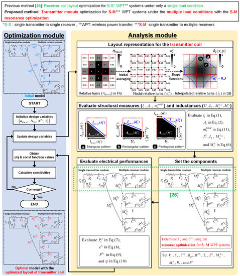
Figure 1.
Concept of the proposed transmitter module optimization for single transmitter to multiple receivers (S-M) wireless power transfer (WPT) systems. Note: Eq.: Equation.
In this paper, a new transmitter module optimization (Figure 1) is proposed to determine the optimal transmitter module, including the optimized transmitter coil, inputvoltage, and compensated capacitances for S-M WPT systems with several given receiver modules. Note that the proposed method can determine the optimal compensated capacitance through the new integration between the transmitter coil layout optimization and the numerical sensitivity-based resonance settings introduced for S-M WPT systems. The proposed method is to maximize the objective function (e.g., total power transfer efficiency in this paper) while satisfying all constraints (e.g., total coil mass used for the transmitter coil and the load voltage required by each receiver module) by using the structural and electrical design variables. The proposed method was applied from a “single transmitter to two receivers” WPT system with two air gaps of 10 mm and 30 mm. The transmitter module optimized by the proposed method was validated through the experiments under the same conditions.
2. Theoretical Framework of Transmitter Module Optimization for S-M WPT Systems
2.1. Structure of the Proposed Framework
As depicted in Figure 1, the proposed optimization framework for designing the transmitter module consists of an optimization module and an analysis module. The procedure of the proposed method is the following:
- In the optimization module, the optimizer gives an initial value of the design variables (i.e., the number of relative turns () and reference turns () for transmitter coil, the number of physical turns for each receiver coil (), and the input voltage ()) to the analysis module. Note that the and are the row number and column number of the FG in the discrete design domain for transmitter coil, as described in Figure A1 in Appendix A.
- In the analysis module, firstly, the optimizer makes a layout of the transmitter coil based on the transferred design variables (i.e., and ). Secondly, self-inductances and mutual inductances (between the generated transmitter coil and receiver coils) are evaluated. Then, the compensated capacitances ( and ) are set based on the concept of the resonance optimization for S-M WPT systems proposed by the author [27], which is newly introduced to the coil layout optimization. Determining the optimal compensated capacitances for S-M WPT systems that can minimize the reactive power and maximize the power transfer efficiency is crucial due to the very complicated mutual inductance among a transmitter and several receiver modules in S-M WPT systems. Finally, the electrical and structural performances (e.g., load voltage of each receiver module (), total power transfer efficiency (), and total transmitter coil mass ()) are calculated by the determined design parameters for S-M WPT systems. The resonance optimization for S-M WPT systems is not equal to the conventional resonance setting for S-S WPT systems [28,29,30,31,32].
- In the optimization module, the objective function (e.g., total power transfer efficiency in this paper), constraint functions (e.g., the load voltage of each receiver module and coil mass), and sensitivities are evaluated from the performances calculated in the analysis module. Then, if the convergence criteria are satisfied, the values of the design variables at the last iteration are determined as the optimal value of the design variables for the S-M WPT systems. If not, this process is continuous by using the design variables updated based on the sensitivities until the convergence criteria are satisfied.
Through this process, the optimizer determines the optimized transmitter module (e.g., transmitter coil layout, input voltage, capacitances, etc.) for S-M WPT systems that can maximize the total power transfer efficiency (i.e., sum of the power transfer efficiency transferred to each receiver in this paper) while satisfying all the constraints (i.e., rated power required by each receiver and total mass used for the transmitter coil). The optimization algorithm used for this work was based on the method of moving asymptotes (MMA) that has been well proven.
2.2. Mathematical Derivation of the Proposed Method
2.2.1. Representation of the Transmitter Coil Layout
The layout of the transmitter coil for the S-M WPT systems can be expressed in terms of the threshold interpolated relative turn () induced by composing of the relative coil turn () and physical coil turns () at the FG at (u, v) in the design space for the transmitter coil, as indicated in Figure 1. The detailed description of the interpolated layout of the transmitter coil is explained in Appendix A.
As shown in the analysis module in Figure 1, with a determined threshold value (), the shapes made by coil segments interpolated in the FGs are divided into three patterns: triangular, rectangular, and pentagonal. Then, the length of the coil segments interpolated at each FG () can be calculated as follows:
where and are the lengths from the intersection between the interpolated coil segment and the sideline of an FG to the closest nodes inside the effective area (i.e., black area in the FG).
The effective area () according to the three patterns in each FG can be derived as:
2.2.2. Electromagnetic and Structural Performance
Assuming that a current flows along the fixed coil of each receiver module () of the S-M WPT system, the magnetic field intensity () at a certain field point P (x, y, z) in the design space of the transmitter coil induced by the coil in ith receiver module can be derived according to Biot_Savart’s law when the receiver coil is represented to interpolate the smooth boundary coil by applying the previous concepts (see Section II.A of our previous paper [24] and Section II.B of our previous paper [25]). Using the sum of the magnetic field intensity at the point P provided by the jth finite coil segment (including the information of the starting point () and the ending point ()) virtually represented for the practical receiver coil to calculate the magnetic field intensity between the receiver coils and transmitter coil, the total magnetic field intensity at the point in the transmitter module can be derived as:
The mutual inductance in the FG at (u, v) in the design area for the transmitter () is calculated as:
where is the magnetic constant or the permeability of free space, is the physical value of the coil turn of the FG at (u, v), is the winding turn of the ith receiver coil, is the surface area in each FG at (u, v) in the design area for the transmitter coil, and ds is a surface vector for the infinitesimal area. Furthermore, assuming that the magnetic field intensity at any point in each FG is nearly constant due to the fine discretization of the FGs, the approximated mutual inductance can be calculated as:
where is the total strength of the magnetic field of the FG at (u, v) provided from the ith receiver module. When the design domain is changed from the FG to the SB representation, the total mutual inductance () between the transmitter coil and the receiver coil in the ith receiver module can be represented as the summation of the effective area ratio at each FG multiplied by its mutual inductance:
In this paper, it is assumed that the mutual inductances between receiver modules are relatively small, which can be ignored. Therefore, using Kirchhoff’s law and the resonance by matching the compensation capacitances ( and ) for S-M WPT systems [27], the input power (), load voltage (), load power (), and total power transfer efficiency () of the S-M WPT systems can be formulated. The input power () supplied to each receiver module, and the total input power () are:
where is the parasitic resistance of the receiver coil in each receiver module, is the parasitic resistance of the transmitter coil, is the load resistance in each receiver module, is the input resistance, is the angular frequency, and is the input voltage. The load voltage () of each receiver module becomes:
The load power () of each receiver module results in:
The total power transfer efficiency () for S-M WPT systems is obtained as:
The total mass of the transmitter coil () is the sum of the mass of the coil segment () interpolated at each FG in the space for designing the transmitter coil:
where ρ is the density of the coil line.
For the layout optimization, the gradients of the major performances (i.e., , , and in this paper) with respect to the design variables (i.e., , , , and ) can be mathematically derived using Equations (8), (10), and (11) with the chain rule of differentiation.
3. Application: S-M WPT Systems with Two Receiver Modules
To improve the convenience and competitiveness of wireless charging systems, the single transmitter to multiple receiver (S-M) WPT systems have been recently researched in various areas (e.g., consumer electronics and electric vehicles). In the application, the proposed framework was applied to optimize the transmitter module for an S-M WPT system (i.e., with two receiver modules) with two different air gaps.
3.1. Model Description
As presented in Figure 2, the application model is composed of an unknown part (i.e., transmitter coils that will be made in the given design space) and the known part (i.e., two receiver modules with one fixed receiver coil, respectively). The proposed method optimizes the transmitter module to extremize (i.e., maximize or minimize) the objective function (e.g., maximization of the power transfer efficiency) while satisfying all constraints (e.g., required performances and regulations) under the given conditions. The detailed information of the model is provided in Table 1. Each air gap () between the transmitter module and the receiver module was given as 10 mm and 30 mm in the two application cases, respectively.
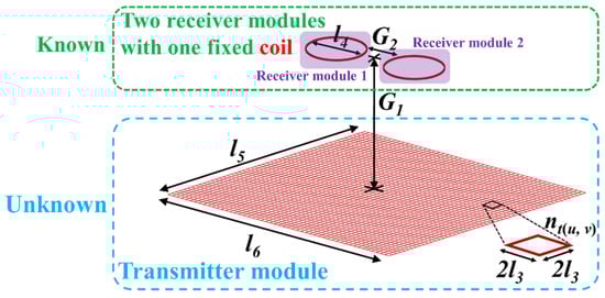
Figure 2.
Description of the application model for S-M WPT systems with two receiver modules.

Table 1.
Detailed information on the application model.
3.2. Optimization for the Application Model
The maximization of the total power transfer efficiency () defined in Equation (10) was set as the objective function to enhance product competitiveness. To enhance portability in a lightweight package, a constraint () was set to keep the total transmitter coil mass () below the available mass ( was set to be 120 g in this paper). For clarification of the presence or absence of material (i.e., coil), black and white filtering () was added as a constraint. This constraint produces a presence (black)-absence (white) design in the FG by using the penalization with a threshold value (α was 0.02 in this paper) for any intermediate values () except 0 (white) and 1 (black). The four constraint functions ( and ) were additionally added to the load voltages () of each wireless charger (i.e., receiver module) to maintain 5 V (), within a 2% margin ( was set to be 0.02 in this paper). The load resistance was 5 Ω to apply 5 W to the load. The design variables were selected as follows: relative turns (), reference turns (), physical turns of the receiver coil (), and input voltage (). The total number of design variables was 1604. The optimization formulation for the model was set as follows:
The sensitivities of the functions (i.e., all the constraints and objective function) with respect to the design variables were analytically derived by the chain rule of differentiation, as described in Appendix B.
The proposed method was applied to the application model with an air gap of 10 mm and 30 mm. Through the optimization process described in Figure 3, the total power transfer efficiency of each case (i.e., objective function) was respectively maximized up to 91.50% and 66.13% while satisfying all constraint functions for the mass of the transmitter coil, black and white filtering, and load voltage required by each receiver. As would be expected, the transmitter coil layouts, input voltage, and compensated capacitances were continuously changed through the iterations to optimize the S-M WPT systems that can extremize the objective function while all constraints are satisfied. Table 2 shows the optimized value of the self-inductances ( and ), mutual inductances ( and ), compensated capacitances ( and ), and input voltage () for the S-M WPT systems, which are determined by the design variables optimized by the proposed method. Note that the compensated capacitances ( and ) for the S-M WPT systems were calculated to minimize the reactive power (i.e., to maximize the power transfer efficiency) under the updated coil layout at each iteration. Appendix C shows the resonance optimization that determines the optimal compensated capacitances ( and ) for the S-M WPT systems at the last iteration for two cases.
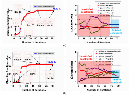
Figure 3.
Optimization history of the transmitter coil layout. (a) Air gap of 10 mm. (b) Air gap of 30 mm.
Table 2.
Optimization results of the inductances, capacitances, and input voltages for two cases.
In the second case, the proposed method tried to improve the power transfer efficiency from the iteration of 75 in the feasible design area that satisfied all constraints. However, it was difficult to increase the efficiency because the load voltage of the receiver module was not satisfied at the iterations of 80, 81, 83, 85, etc. The main reason why the efficiency was not improved more can be that the physical strength of the magnetic flux according to the distance between the transmission coil and receiver coil cannot increase the efficiency while maintaining the required rated powers, although the change of the transmitter module was tried.
3.3. Experimental Validation
As indicated in Figure 4, the determined optimal transmitter coils were transformed to the experimental coil for experimental validation. Figure 5 shows the experimental setting for the experimental validation. A low-power AC signal with 100 kHz was produced by a waveform generator (Agilent 33500B). Then, the low-power signal was changed to a high-power AC current by the power amplifier (NF HAS 4014). The AC current operates the S-M WPT systems.
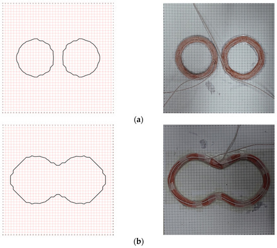
Figure 4.
Optimized transmitter coil according to the air gap of 10 mm and 30 mm (the left and right columns show the transmitter coil optimized by the proposed method and transmitter coils fabricated for experiments, respectively). In the case of the 10 mm air gap, the optimized transmitter coil is a single transmitter coil connected in series, although the number of the topology for the transmitter coil made by the proposed method is two. (a) Air gap of 10 mm; (b) Air gap of 30 mm.
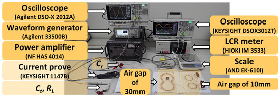
Figure 5.
Experiment for validating the optimized S-M WPT systems with two receiver modules according to the 10 mm and 30 mm air gaps.
As explained in Table 3, there were errors between the optimization results and experimental results caused by the handmade manufacturing and abovementioned assumptions. The error of the total power transfer efficiency (8.12%) is the sum of the power transfer efficiency for each receiver. As indicated in Equations (8)–(10), because the error of the power transfer efficiency is bigger when the load voltage has an error, the amount of the total power transfer efficiency for S-M WPT systems (8.17%) was more than the load voltage (0.41~2.65%). Although the maximum percentage error between them was near 8.17%, it can be validated that the proposed method be used to systematically design the optimal transmitter coil layout for S-M WPT systems that can maximize the total power transfer efficiency while all given constraints are satisfied.
Table 3.
Comparison between the proposed optimization and experiment.
4. Conclusions
A new transmitter module optimization for S-M WPT systems was proposed to maximize the total power transfer efficiency while satisfying the constraints (e.g., the load voltage required by each receiver module and total available mass for the transmitter coil). The proposed method is a mathematical optimization method for designing S-M WPT systems based on the analytical (for transmitter coil layout) and numerical (for compensated capacitance for resonance setting) sensitivities for the structural (e.g., mass) and electrical performances (e.g., rated power and power transfer efficiency). The proposed method was applied to the single transmitter to two-receiver WPT systems. Through the comparison of the optimization results and the experiment results, the potential of the proposed method for optimizing the transmitter coil of the S-M WPT system was validated.
Author Contributions
Both authors contributed equally in writing this article. All authors have read and agreed to the published version of the manuscript.
Funding
This research was supported in part by the “Human Resources Program in Energy Technology” of the Korea Institute of Energy Technology Evaluation and Planning (KETEP), granted financial resources from the Ministry of Trade, Industry, and Energy, Republic of Korea. (No. 20204010600470) and in part by the National Research Foundation of Korea (NRF) grant funded by the Korean government (MSIT) (No. 2021R1F1A105819411).
Institutional Review Board Statement
Not applicable.
Informed Consent Statement
Not applicable.
Data Availability Statement
Not applicable.
Acknowledgments
The authors would like to thank In Gwun Jang for valuable discussions.
Conflicts of Interest
The authors declare no conflict of interest.
Appendix A
Based on the concepts described in Section II.B.1 in our previous research [26], to minimize the gray zones and zig-zag patterns made by the FG-based coil representation used for transmitter coil layout, the discrete relative turns () in the FGs for representing the coil layout are converted to the continuous interpolated relative turn in the SB with an introduction to the nodal relative turns and shape function matrix [25]. As shown in Figure A1, the process for converting from FG to SB is followed as:
(1) Convert the continuous design domain for the transmitter coil into the equivalent discrete design space that is composed of a set of FGs with the same current flow (I), size, and shape, as depicted in Figure A1.

Figure A1.
Fixed grid (FG)-based design domain representation for the transmitter coil.
(2) Assign a relative coil turn (0 < ≤ 1) and a reference coil turn () to each FG. Then, the physical coil turns () of the FG at (u, v) can be described as:
Note that the relative coil turn and reference coil turn are the design variables, which are updated at every iteration during optimization.
(3) Calculate the relative nodal turn () of each node through the assumption that the relative coil turn of each FG is decomposed into four nodes of each FG. The relative nodal turn () is defined as the average of the relative turn in all FGs that share the target node (d) as:
(4) Express the shape function vector (N) for a bilinear quadrilateral element (FG in this case) composed of four nodes, as follows:
where x and y are the local coordinates centered in the FG and is half of the side length of each FG. The shape functions can be used to interpolate a target physical field based on the discrete nodal values [25].
(5) Convert to the linearly (or smoothly) interpolated relative turn () in each FG in the SB representation from the discrete relative turns () of each FG in the FG-based representation, as follows:
where is a vector of the relative nodal turns. Thus, if one of the values of the interpolated relative turn (0 < ≤ 1) makes the electrical performance in FG equal to SB, it is determined as a threshold value, and a smooth layout of the transmitter coil in the SB representation can be constructed. For example, if the electrical performances in SB are the same as those in FG when the threshold value () is 0.3, the threshold value of is determined as 0.3, and the smooth coil layout is made, as shown in Figure 1.
Appendix B
Then, the analytical sensitivities of all functions for optimization ( in Equation (12)) with respect to the relative turns of the transmitter coil () can be calculated by the chain rule of differentiation on Equations (A4), (8), (10) and (11), as follows:
Furthermore, the sensitivities of all functions with respect to the reference turns of the transmitter coil () can be expressed as:
Similarly, for the physical turns of the coil in each receiver (),
Finally, for the input voltage (),
Note that, in Equations (A7) and (A8), the sensitivities of the coil mass constraint () and black-and-white filtering constraint (), with respect to the physical turns of the coil in each receiver () and the input voltage (), are zero. This means that these design variables ( and ) are not relevant to the constraints ( and ). By contrast, in Equation (A5), the sensitivities with respect to the relative turns of the transmitter coil () are non-zero, which means that the design variable () affects all of the functions ( in Equation (12)) by the number of sensitivities during optimization.
Appendix C
In order to minimize the reactive power and maximize the power transfer efficiency, while the rated powers required by the receiver module are satisfied, the optimal compensated capacitances can be determined by the resonance optimization for S-M WPT systems [27] based on the electrical design parameters as indicated in Table 2. As design variables, the compensated capacitance () in the transmitter module and two compensated capacitances in the receiver module (, and in Figure 1, respectively) were selected.
The objective function was set to maximize the efficiency of the power transfer (). The constraints were set as the maintenance of the induced voltage required by each receiver (i.e., (5 V) in this paper) with a margin of (0.2%). The optimization formulation for the resonance determination was formulated as follows:
Through optimization, the optimal value of the compensated capacitances for the S-M WPT system was determined, as indicated in Table 2. Figure A2 and Figure A3 show the optimization history and reactive power, respectively.
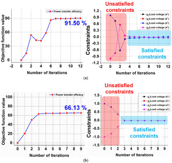
Figure A2.
Optimized history for setting resonance for the S-M WPT systems with the air gap of 10 mm and 30 mm. (a) Air gap of 10 mm; (b) Air gap of 30 mm.
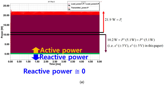
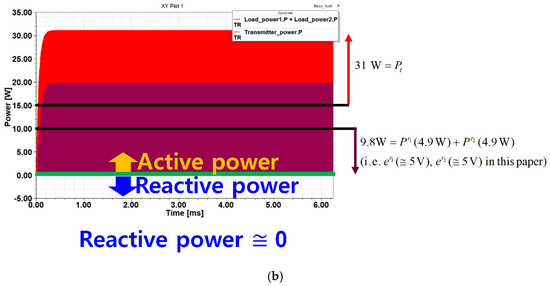
Figure A3.
Reactive power at the optimal resonance setting for S-M WPT systems according to the air gap of 10 mm and 30 mm. (a) Air gap of 10 mm; (b) Air gap of 30 mm.
References
- Liu, Y.; Li, B.; Huang, M.; Chen, Z.; Zhang, X. An Overview of Regulation Topologies in Resonant Wireless Power Transfer Systems for Consumer Electronics or Bio-Implants. Energies 2018, 11, 1737. [Google Scholar] [CrossRef] [Green Version]
- Narayanamoorthi, R.; Juliet, A.V.; Chokkalingam, B. Frequency splitting-based wireless power transfer and simultaneous propulsion generation to multiple micro-robots. IEEE Sens. J. 2018, 18, 5566–5575. [Google Scholar] [CrossRef]
- Zhang, Z.; Zhang, B. Omnidirectional and efficient wireless power transfer system for logistic robots. IEEE Access 2020, 8, 13683–13693. [Google Scholar] [CrossRef]
- Sarin, A.; Avestruz, A.-T. Code division multiple access wireless power transfer for energy sharing in heterogenous robot swarms. IEEE Access 2020, 8, 132121–132133. [Google Scholar] [CrossRef]
- Lee, E.S.; Choi, B.G.; Kim, M.Y.; Han, S.H. Optimal number of turns design of the IPT coils for laptop wireless charging. IEEE Access 2021, 9, 19548–19561. [Google Scholar] [CrossRef]
- Mohamed, A.; Marim, A.A.; Mohammed, O. Magnetic design considerations of bidirectional inductive wireless power transfer system for EV applications. IEEE Trans. Magn. 2017, 53, 1–5. [Google Scholar] [CrossRef]
- Cota, K.A.; Gray, P.A.; Pathmanathan, M.; Lehn, P.W. An approach for selecting compensation capacitances in resonance-based EV wireless power transfer systems with switched capacitors. IEEE Trans. Transp. Electrif. 2019, 5, 1004–1014. [Google Scholar] [CrossRef]
- Zhang, Y.; Wang, L.; Guo, Y.; Tao, C. Null-coupled magnetic integration for EV wireless power transfer system. IEEE Trans. Transp. Electrif. 2019, 5, 968–976. [Google Scholar] [CrossRef]
- Lee, J.-Y.; Han, B.-M. A bidirectional wireless power transfer EV charger using self-resonant PWM. IEEE Trans. Power Electron. 2014, 30, 1784–1787. [Google Scholar] [CrossRef]
- Huang, C.; Kawajiri, T.; Ishikuro, H. A 13.56-MHz wireless power transfer system with enhanced load-transient response and efficiency by fully integrated wireless constant-idle-time control for biomedical implants. IEEE J. Solid State Circuits 2017, 53, 538–551. [Google Scholar] [CrossRef]
- Wang, Q.; Che, W.; Mongiardo, M.; Monti, G. Wireless power transfer system with high misalignment tolerance for bio-medical implants. IEEE Trans. Circuits Syst. II Express Br. 2020, 67, 3023–3027. [Google Scholar] [CrossRef]
- Basar, R.; Ahmad, M.Y.; Cho, J.; Ibrahim, F. An Improved wearable resonant wireless power transfer system for biomedical capsule endoscope. IEEE Trans. Ind. Electron. 2018, 65, 7772–7781. [Google Scholar] [CrossRef]
- Tran, D.H.; Vu, V.B.; Choi, W. Design of a high-efficiency wireless power transfer system with intermediate coils for the on-board chargers of electric vehicles. IEEE Trans. Power Electron. 2018, 33, 175–187. [Google Scholar] [CrossRef]
- Liu, X.; Wang, G. A novel wireless power transfer system with double intermediate resonant coils. IEEE Trans. Ind. Electron. 2015, 63, 2174–2180. [Google Scholar] [CrossRef]
- Chabalko, M.J.; Sample, A. Three-dimensional charging via multimode resonant cavity enabled wireless power transfer. IEEE Trans. Power Electron. 2015, 30, 6163–6173. [Google Scholar] [CrossRef]
- Zhong, W.; Zhang, C.; Liu, X.; Hui, S.Y.R. A methodology for making a three-coil wireless power transfer system more energy efficient than a two-coil counterpart for extended transfer distance. IEEE Trans. Power Electron. 2014, 30, 933–942. [Google Scholar] [CrossRef]
- Li, H.; Li, J.; Wang, K.; Chen, W.; Yang, X. A maximum efficiency point tracking control scheme for wireless power transfer systems using magnetic resonant coupling. IEEE Trans. Power Electron. 2015, 30, 3998–4008. [Google Scholar] [CrossRef]
- Moon, S.; Moon, G.-W. Wireless power transfer system with an asymmetric 4-coil resonator for electric vehicle battery chagers. In Proceedings of the IEEE Applied Power Electronics Conference and Exposition, Charlotte, NC, USA, 15–19 March 2015; pp. 1650–1657. [Google Scholar] [CrossRef]
- Choi, S.Y.; Gu, B.W.; Jeong, S.Y.; Rim, C.T. Advances in wireless power transfer systems for roadway-powered electric vehicles. IEEE J. Emerg. Sel. Top. Power Electron. 2015, 3, 18–36. [Google Scholar] [CrossRef]
- Bosshard, R.; Kolar, J.W.; Muhlethaler, J.; Stevanovic, I.; Wunsch, B.; Canales, F. Modeling and η–α-Pareto Optimization of inductive power transfer coils for electric vehicles. IEEE J. Emerg. Sel. Top. Power Electron. 2015, 3, 50–64. [Google Scholar] [CrossRef]
- Kim, H.; Song, C.; Kim, D.; Jung, D.H.; Kim, I.-M.; Kim, Y.-I.; Kim, J.; Ahn, S.; Kim, J. Coil design and measurements of automotive magnetic resonant wireless charging system for high-efficiency and low magnetic field leakage. IEEE Trans. Microw. Theory Tech. 2016, 64, 383–400. [Google Scholar] [CrossRef]
- Lee, S.B.; Ahn, S.; Jang, I.G. Development of the optimization framework for low-power wireless power transfer systems. IEEE Trans. Microw. Theory Tech. 2015, 63, 813–820. [Google Scholar] [CrossRef]
- Lee, S.B.; Ahn, S.; Jang, I.G. Simulation-based feasibility study on the wireless charging railway system with a ferriteless primary module. IEEE Trans. Veh. Technol. 2017, 66, 1004–1010. [Google Scholar] [CrossRef]
- Lee, S.B.; Jang, I.G. Layout optimization of the receiver coils for multitransmitter wireless power transfer systems. IEEE J. Emerg. Sel. Top. Power Electron. 2017, 5, 1311–1321. [Google Scholar] [CrossRef]
- Lee, S.B.; Lee, C.; Jang, I.G. Precise determination of the optimal coil for wireless power transfer systems through postprocessing in the smooth boundary representation. IEEE Trans. Magn. 2017, 53, 1–4. [Google Scholar] [CrossRef]
- Lee, S.B.; Jang, I.G. Coil layout optimization for maximizing the power transfer efficiency of wireless power transfer systems with multiple transmitter coils. IEEE J. Emerg. Sel. Top. Power Electron. 2019, 8, 2672–2681. [Google Scholar] [CrossRef]
- Lee, S.B.; Kim, M.; Jang, I.G. Determination of the optimal resonant condition for multireceiver wireless power transfer systems considering the transfer efficiency and different rated powers with altered coupling effects. IEEE J. Emerg. Sel. Top. Power Electron. 2021, 9, 2384–2393. [Google Scholar] [CrossRef]
- Kim, J.; Kim, D.-H.; Park, Y.-J. Analysis of capacitive impedance matching networks for simultaneous wireless power transfer to multiple devices. IEEE Trans. Ind. Electron. 2015, 62, 2807–2813. [Google Scholar] [CrossRef]
- Lim, Y.; Tang, H.; Lim, S.; Park, J. An adaptive impedance-matching network based on a novel capacitor matrix for wireless power transfer. IEEE Trans. Power Electron. 2014, 29, 4403–4413. [Google Scholar] [CrossRef]
- Beh, T.C.; Kato, M.; Imura, T.; Oh, S.; Hori, Y. Automated impedance matching system for robust wireless power transfer via magnetic resonance coupling. IEEE Trans. Ind. Electron. 2012, 60, 3689–3698. [Google Scholar] [CrossRef]
- Chen, L.; Liu, S.; Zhou, Y.C.; Cui, T.J. An optimizable circuit structure for high-efficiency wireless power transfer. IEEE Trans. Ind. Electron. 2013, 60, 339–349. [Google Scholar] [CrossRef]
- Ahn, D.; Hong, S. A study on magnetic field repeater in wireless power transfer. IEEE Trans. Ind. Electron. 2012, 60, 360–371. [Google Scholar] [CrossRef]
Publisher’s Note: MDPI stays neutral with regard to jurisdictional claims in published maps and institutional affiliations. |
© 2021 by the authors. Licensee MDPI, Basel, Switzerland. This article is an open access article distributed under the terms and conditions of the Creative Commons Attribution (CC BY) license (https://creativecommons.org/licenses/by/4.0/).