
Improved Rotor Flux and Torque Control Based on the Third-Order Sliding Mode Scheme Applied to the Asynchronous Generator for the Single-Rotor Wind Turbine


Abstract
:1. Introduction
- A new TOSMC method based on the DFTC method was designed to minimize ripples of both rotor flux and electromagnetic torque;
- Third-order sliding mode controllers reduces the tracking error for rotor flux and electromagnetic torque toward the references of AG-based SRWT systems; and
- The DFTC-TOSMC method with SVM strategy reduces harmonic distortion of the stator current and torque ripple of AG-based SRWT systems.
2. Single-Rotor Wind Power
3. The AG Model
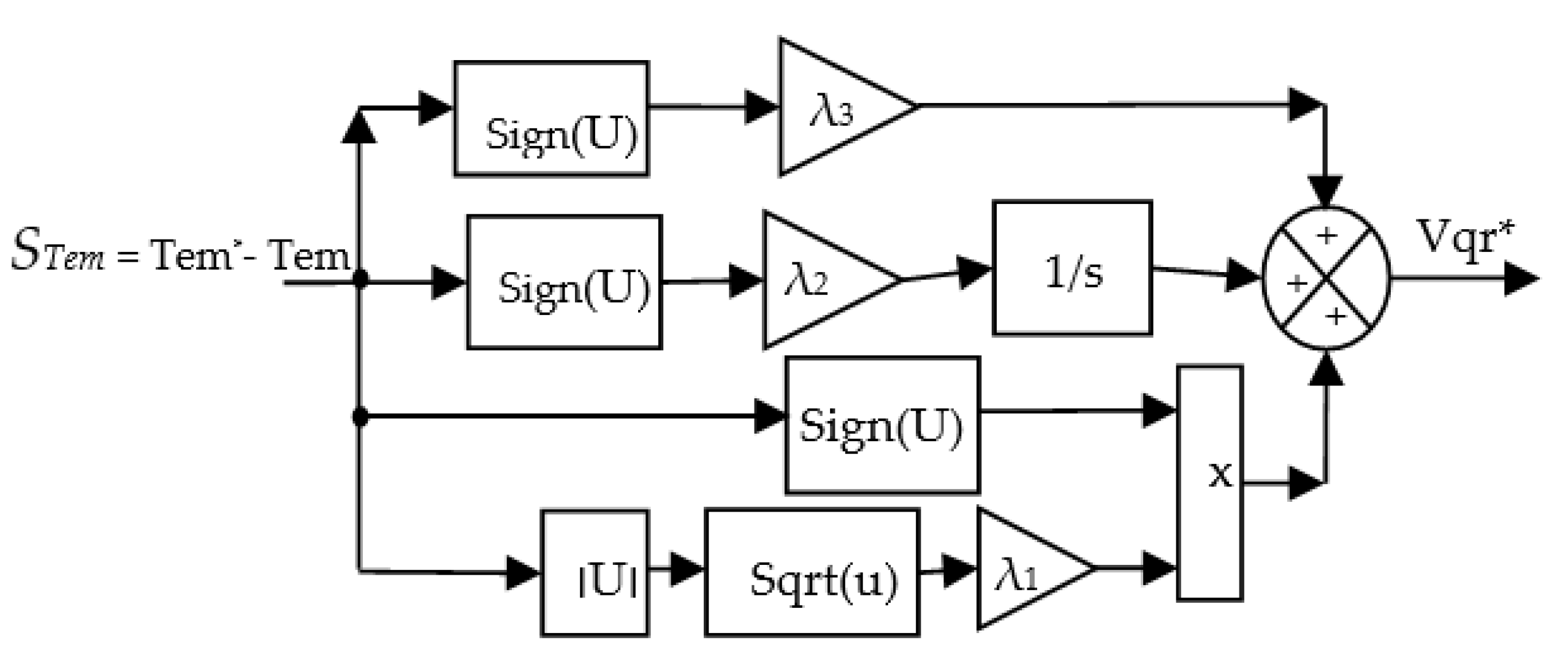
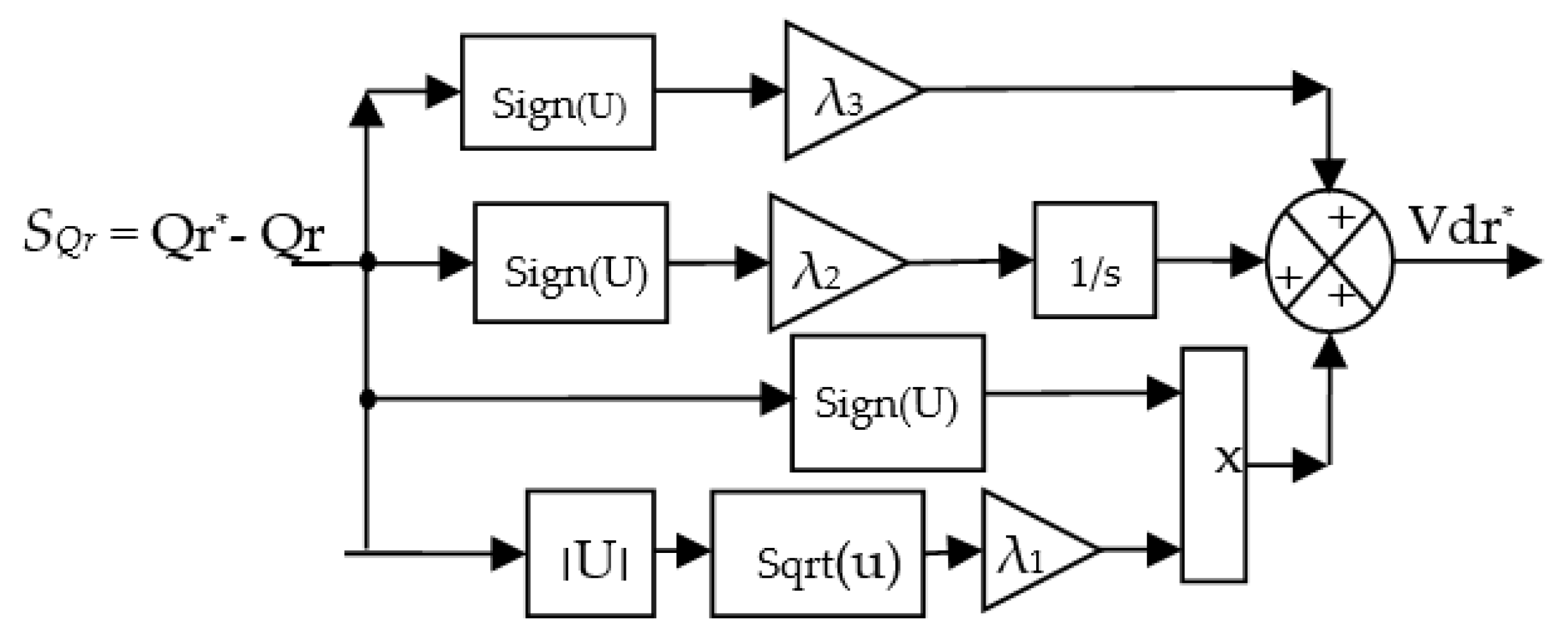
4. Third-Order Sliding Mode Controller
5. DFTC-TOSMC Control of the AG-Based SRWP
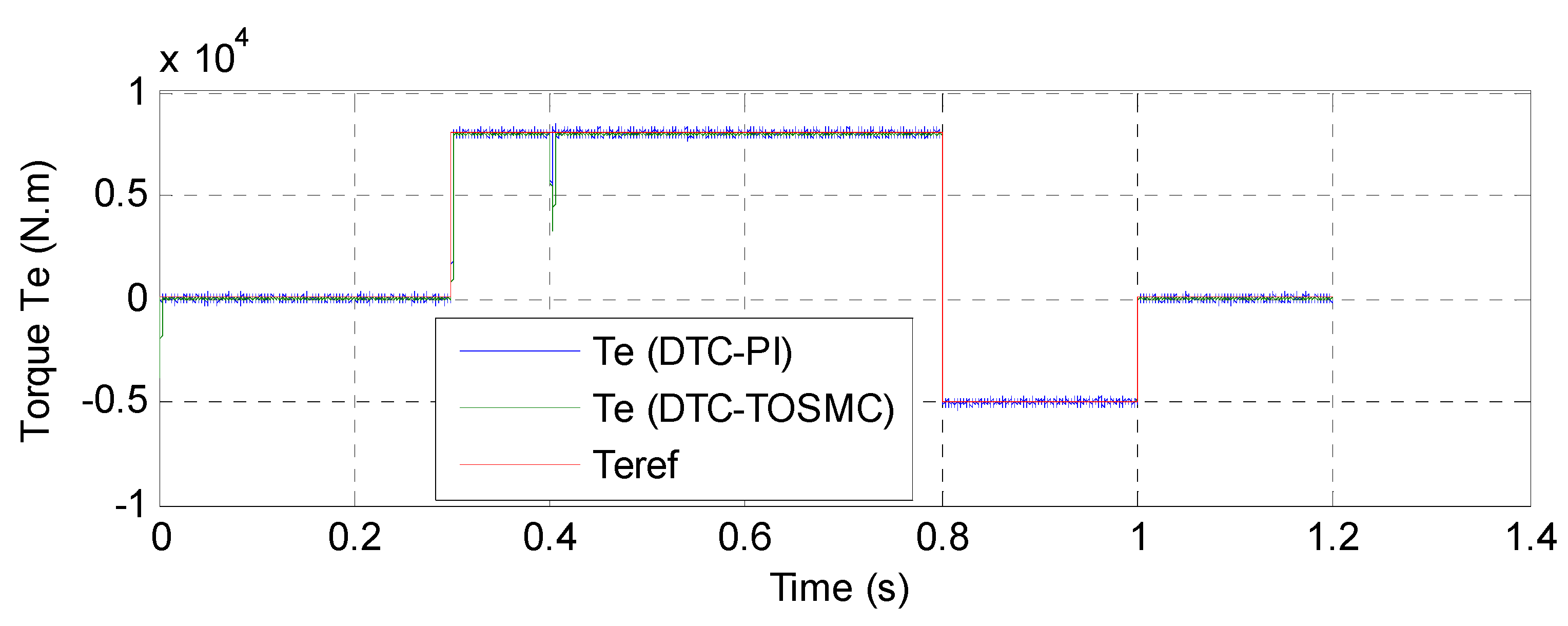
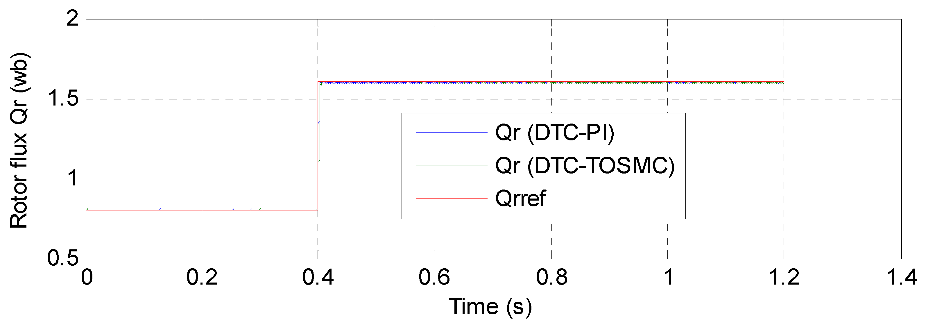
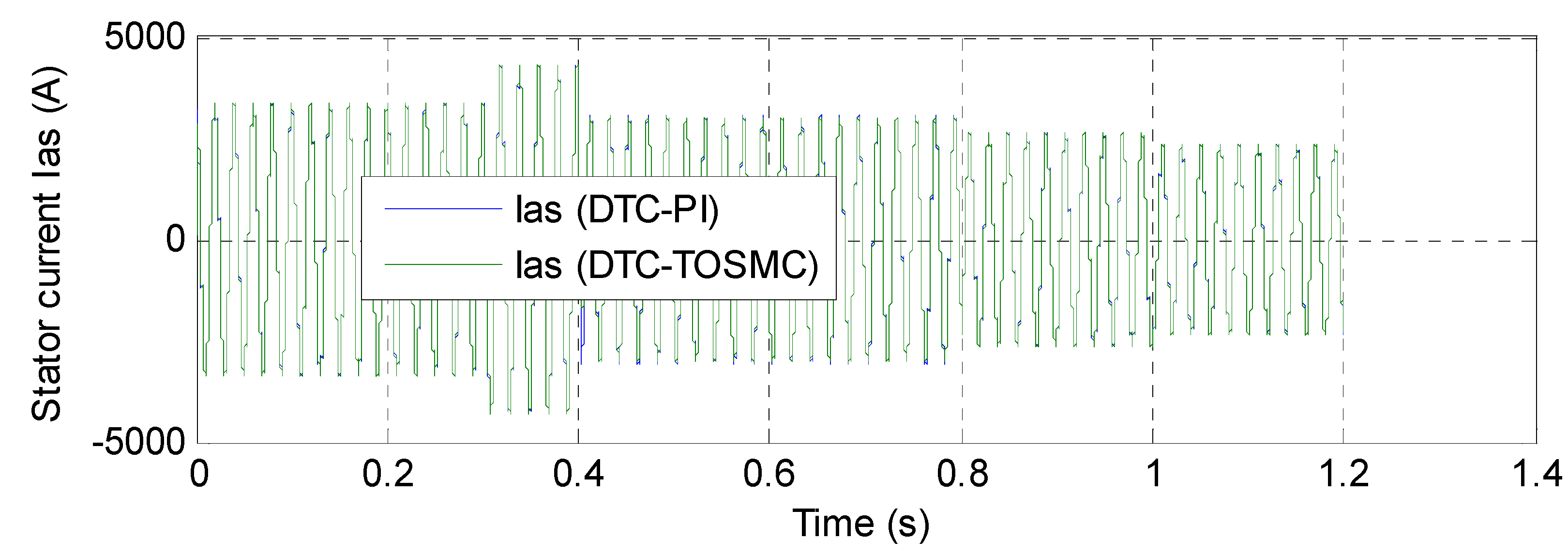
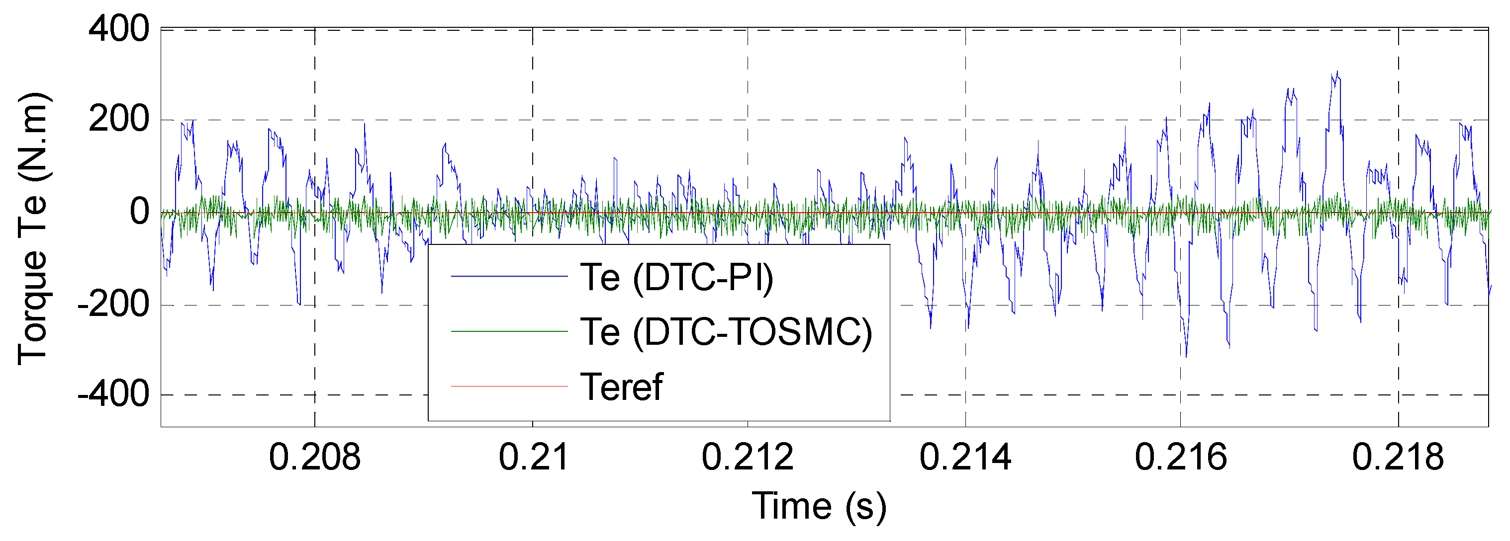
6. Analysis of the Simulation Results
7. Discussion
8. Conclusions
- Reduces the electromagnetic torque and rotor flux;
- Simple control was proposed;
- Minimization of the total harmonic distortion of stator current by 64.81%; and
- A new nonlinear controller was presented and confirmed with numerical simulation.
Author Contributions
Funding
Institutional Review Board Statement
Informed Consent Statement
Data Availability Statement
Conflicts of Interest
List of Symbols
| ϕr, ϕr* | Actual and reference rotor flux |
| Vs, Is | Vectors of the stator voltage and current |
| Vra,b,c, Ira,b,c | Rotor voltage and current in abc frame |
| Vα,β, Iα,β | Voltage and current in αβ frame |
| Te, Te* | Actual and reference torques |
| ωn, ωr | Nominal and rotor speeds |
| Rs, Rr | Stator and rotor resistances |
| ϕαs, ϕβs | Stator flux components in αβ frame |
| θr | Rotor flux angle |
| Ki, Kp | Integral and proportional gains |
| Lr, Ls, Lm | Rotor, stator and mutual inductances |
| p | Generator pole pairs |
| Wb | Weber (unit) |
| Hz | Hertz (unit) |
| Mw | Migawatt (Unit) |
| mH | Millihenry (unit) |
| N.m | Newton-meter (Unit) |
List of Acronyms
| DTC | Direct torque control |
| PI | Proportional integral |
| DPC | Direct power control |
| SMC | Sliding mode control |
| DFTC | Direct flux and torque control |
| THD | Total harmonic distortion |
| SOCSMC | Second-order continuous sliding mode control |
| FOC | Field oriented control |
| FSMC | Fuzzy sliding mode control |
| SVM | Space vector modulation |
| IP | Integral-proportional |
| AG | Asynchronous generator |
| TOSMC | Third-order sliding mode controller |
| STA | Super twisting algorithm |
| THD | Total harmonic distortion |
| ISM | Integral sliding mode. |
| MRSMC | Multi-resonant-based sliding mode controller |
| ISMC | Integral sliding mode controller. |
Appendix A

References
- Wang, F.; Zhang, Z.; Mei, X.; Rodríguez, J.; Kennel, R. Advanced Control Strategies of Induction Machine: Field Oriented Control, Direct Torque Control and Model Predictive Control. Energies 2018, 11, 120. [Google Scholar] [CrossRef] [Green Version]
- Kim, S.J.; Kim, J.-W.; Park, B.-G.; Lee, D.-H. A Novel Predictive Direct Torque Control Using an Optimized PWM Approach. IEEE Trans. Ind. Appl. 2021, 57, 2537–2546. [Google Scholar] [CrossRef]
- Reddy, C.U.; Prabhakar, K.K.; Singh, A.K.; Kumar, P. Speed Estimation Technique Using Modified Stator Current Error-Based MRAS for Direct Torque Controlled Induction Motor Drives. IEEE J. Emerg. Sel. Top. Power Electron. 2020, 8, 1223–1235. [Google Scholar] [CrossRef]
- Abosh, A.H.; Zhu, Z.Q.; Ren, Y. Reduction of Torque and Flux Ripples in Space Vector Modulation-Based Direct Torque Control of Asymmetric Permanent Magnet Synchronous Machine. IEEE Trans. Power Electron. 2017, 32, 2976–2986. [Google Scholar] [CrossRef]
- Khoucha, F.; Khoudir, M.; Kheloui, A.; Benbouzid, M. Electric Vehicle Induction Motor DSVM-DTC with Torque Ripple Minimization. Int. Rev. Electr. Eng. 2009, 4, 501–508. [Google Scholar]
- Mossa, M.A.; Duc Do, T.; Saad Al-Sumaiti, A.; Quynh, N.V.; Diab, A.A.Z. Effective Model Predictive Voltage Control for a Sensorless Doubly Fed Induction Generator. IEEE Can. J. Electr. Comput. Eng. 2021, 44, 50–64. [Google Scholar] [CrossRef]
- Alsofyani, I.M.; Lee, K.-B. Evaluation of Direct Torque Control with a Constant-Frequency Torque Regulator under Various Discrete Interleaving Carriers. Electronics 2019, 8, 820. [Google Scholar] [CrossRef] [Green Version]
- Wu, C.; Zhou, D.; Blaabjerg, F. Direct Power Magnitude Control of DFIG-DC System without Orientation Control. IEEE Trans. Ind. Electron. 2021, 68, 1365–1373. [Google Scholar] [CrossRef]
- Do, T.D.; Choi, H.H.; Jung, J. Nonlinear Optimal DTC Design and Stability Analysis for Interior Permanent Magnet Synchronous Motor Drives. IEEE/ASME Trans. Mechatron. 2015, 20, 2716–2725. [Google Scholar] [CrossRef]
- Mazen Alhato, M.; Bouallègue, S.; Rezk, H. Modeling and Performance Improvement of Direct Power Control of Doubly-Fed Induction Generator Based Wind Turbine through Second-Order Sliding Mode Control Approach. Mathematics 2020, 8, 2012. [Google Scholar] [CrossRef]
- Xiong, C. A Fault-Tolerant FOC Strategy for Five-Phase SPMSM with Minimum Torque Ripples in the Full Torque Operation Range Under Double-Phase Open-Circuit Fault. IEEE Trans. Ind. Electron. 2020, 67, 9059–9072. [Google Scholar] [CrossRef]
- Venkatesh, N.; Satish, K.G. An Enhanced Exponential Reaching Law Based Sliding Mode Control Strategy for a Three Phase UPS System. Serb. J. Electr. Eng. 2020, 17, 313–336. [Google Scholar] [CrossRef]
- Velasco, J.; Calvo, I.; Barambones, O.; Venegas, P.; Napole, C. Experimental Validation of a Sliding Mode Control for a Stewart Platform Used in Aerospace Inspection Applications. Mathematics 2020, 8, 2051. [Google Scholar] [CrossRef]
- Alanis, A.Y.; Munoz-Gomez, G.; Rivera, J. Nested High Order Sliding Mode Controller with Back-EMF Sliding Mode Observer for a Brushless Direct Current Motor. Electronics 2020, 9, 1041. [Google Scholar] [CrossRef]
- Gao, P.; Zhang, G.; Lv, X. Model-Free Hybrid Control with Intelligent Proportional Integral and Super-Twisting Sliding Mode Control of PMSM Drives. Electronics 2020, 9, 1427. [Google Scholar] [CrossRef]
- Zhang, C.; Lin, Z.; Yang, S.X.; He, J. Total-Amount Synchronous Control Based on Terminal Sliding-Mode Control. IEEE Access 2017, 5, 5436–5444. [Google Scholar] [CrossRef]
- Haibo, L.; Heping, W.; Junlei, S. Attitude control for QTR using exponential nonsingular terminal sliding mode control. J. Syst. Eng. Electr. 2019, 30, 191–200. [Google Scholar] [CrossRef]
- Lin, X.; Shi, X.; Li, S. Adaptive Tracking Control for Spacecraft Formation Flying System via Modified Fast Integral Terminal Sliding Mode Surface. IEEE Access 2020, 8, 198357–198367. [Google Scholar] [CrossRef]
- Wang, Z.; Li, S.; Li, Q. Discrete-Time Fast Terminal Sliding Mode Control Design for DC–DC Buck Converters with Mismatched Disturbances. IEEE Trans. Ind. Inform. 2020, 16, 1204–1213. [Google Scholar] [CrossRef]
- Yusoff, N.A.; Razali, A.M.; Karim, K.A.; Sutikno, T.; Jidin, A. A Concept of Virtual-Flux Direct Power Control of Three-Phase AC-DC Converter. Int. J. Power Electron. Drive Syst. 2017, 8, 1776–1784. [Google Scholar] [CrossRef]
- Amrane, F.; Chaiba, A.; Babes, B.E.; Mekhilef, S. Design and implementation of high performance field oriented control for grid-connected doubly fed induction generator via hysteresis rotor current controller. Rev. Roum. Sci. Techn.-Electrotechn. Energ. 2016, 61, 319–324. [Google Scholar]
- Benbouhenni, H.; Bizon, N. Terminal Synergetic Control for Direct Active and Reactive Powers in Asynchronous Generator-Based Dual-Rotor Wind Power Systems. Electronics 2021, 10, 1880. [Google Scholar] [CrossRef]
- Boudjema, Z.; Meroufel, A.; Djerriri, Y.; Bounadja, E. Fuzzy sliding mode control of a doubly fed induction generator for energy conversion. Carpath. J. Electron. Comput. Eng. 2013, 6, 7–14. [Google Scholar]
- Boudjema, Z.; Taleb, R.; Djerriri, Y.; Yahdou, A. A novel direct torque control using second order continuous sliding mode of a doubly fed induction generator for a wind energy conversion system. Turk. J. Electr. Eng. Comput. Sci. 2017, 25, 965–975. [Google Scholar] [CrossRef] [Green Version]
- Fayssal, A.; Bruno, F.; Azeddine, C. Experimental investigation of efficient and simple wind-turbine based on DFIG-direct power control using LCL-filter for stand-alone mode. ISA Trans. 2021, 1–34, in press. [Google Scholar] [CrossRef]
- Shehata, E.G. Sliding mode direct power control of RSC for DFIGs driven by variable speed wind turbines. Alex. Eng. J. 2015, 54, 1067–1075. [Google Scholar] [CrossRef] [Green Version]
- Benbouhenni, H.; Bizon, N. A Synergetic Sliding Mode Controller Applied to Direct Field-Oriented Control of Induction Generator-Based Variable Speed Dual-Rotor Wind Turbines. Energies 2021, 14, 4437. [Google Scholar] [CrossRef]
- Habib, B.; Lemdani, S. Combining synergetic control and super twisting algorithm to reduce the active power undulations of doubly fed induction generator for dual-rotor wind turbine system. Electr. Eng. Electromech. 2021, 3, 8–17. [Google Scholar] [CrossRef]
- Alhato, M.M.; Ibrahim, M.N.; Rezk, H.; Bouallègue, S. An Enhanced DC-Link Voltage Response for Wind-Driven Doubly Fed Induction Generator Using Adaptive Fuzzy Extended State Observer and Sliding Mode Control. Mathematics 2021, 9, 963. [Google Scholar] [CrossRef]
- Chen, S.Z.; Cheung, N.C.; Chung Wong, K.; Wu, J. Integral Sliding-Mode Direct Torque Control of Doubly-Fed Induction Generators Under Unbalanced Grid Voltage. IEEE Trans. Energy Convers. 2010, 25, 356–368. [Google Scholar] [CrossRef]
- Klarmann, K.; Thielmann, M.; Schumacher, W. Comparison of Hysteresis Based PWM Schemes ΔΣ-PWM and Direct Torque Control. Appl. Sci. 2021, 11, 2293. [Google Scholar] [CrossRef]
- Najib, E.; Aziz, D.; Abdelaziz, E.; Mohammed, T.; Youness, E.; Khalid, M.; Badre, B. Direct torque control of doubly fed induction motor using three-level NPC inverter. Protect. Control Mod. Power Syst. 2019, 4, 1–9. [Google Scholar] [CrossRef] [Green Version]
- Cortajarena, J.A.; Barambones, O.; Alkorta, P.; Cortajarena, J. Grid Frequency and Amplitude Control Using DFIG Wind Turbines in a Smart Grid. Mathematics 2021, 9, 143. [Google Scholar] [CrossRef]
- Yin, M. Turbine Stability-Constrained Available Wind Power of Variable Speed Wind Turbines for Active Power Control. IEEE Trans. Power Syst. 2017, 32, 2487–2488. [Google Scholar] [CrossRef]
- Hemeyine, A.V.; Abbou, A.; Bakouri, A.; Mokhlis, M.; El Moustapha, S.M.o.M. A Robust Interval Type-2 Fuzzy Logic Controller for Variable Speed Wind Turbines Based on a Doubly Fed Induction Generator. Inventions 2021, 6, 21. [Google Scholar] [CrossRef]
- Mahfoud, S.; Derouich, A.; EL Ouanjli, N.; EL Mahfoud, M.; Taoussi, M. A New Strategy-Based PID Controller Optimized by Genetic Algorithm for DTC of the Doubly Fed Induction Motor. Systems 2021, 9, 37. [Google Scholar] [CrossRef]
- Nguyen, T.-T. A Rotor-Sync Signal-Based Control System of a Doubly-Fed Induction Generator in the Shaft Generation of a Ship. Processes 2019, 7, 188. [Google Scholar] [CrossRef] [Green Version]
- Pan, L.; Zhu, Z.; Xiong, Y.; Shao, J. Integral Sliding Mode Control for Maximum Power Point Tracking in DFIG Based Floating Offshore Wind Turbine and Power to Gas. Processes 2021, 9, 1016. [Google Scholar] [CrossRef]
- Yousefi-Talouki, A.; Zalzar, S.; Pouresmaeil, E. Direct Power Control of Matrix Converter-Fed DFIG with Fixed Switching Frequency. Sustainability 2019, 11, 2604. [Google Scholar] [CrossRef] [Green Version]
- Ma, Y.; Liu, J.; Liu, H.; Zhao, S. Active-Reactive Additional Damping Control of a Doubly-Fed Induction Generator Based on Active Disturbance Rejection Control. Energies 2018, 11, 1314. [Google Scholar] [CrossRef] [Green Version]
- Giaourakis, D.G.; Safacas, A.N. Effect of Short-Circuit Faults in the Back-to-Back Power Electronic Converter and Rotor Terminals on the Operational Behavior of the Doubly-Fed Induction Generator Wind Energy Conversion System. Machines 2015, 3, 2–26. [Google Scholar] [CrossRef] [Green Version]
- Abdelrahem, M.; Hackl, C.M.; Kennel, R. Limited-Position Set Model-Reference Adaptive Observer for Control of DFIGs without Mechanical Sensors. Machines 2020, 8, 72. [Google Scholar] [CrossRef]
- Benbouhenni, H.; Boudjema, Z.; Belaidi, A. Direct power control with NSTSM algorithm for DFIG using SVPWM technique. Iran. J. Electr. Electron. Eng. 2021, 17, 1–11. [Google Scholar]
- Farajpour, Y.; Alzayed, M.; Chaoui, H.; Kelouwani, S. A Novel Switching Table for a Modified Three-Level Inverter-Fed DTC Drive with Torque and Flux Ripple Minimization. Energies 2020, 13, 4646. [Google Scholar] [CrossRef]
- Hakami, S.S.; Mohd Alsofyani, I.; Lee, K.-B. Low-Speed Performance Improvement of Direct Torque Control for Induction Motor Drives Fed by Three-Level NPC Inverter. Electronics 2020, 9, 77. [Google Scholar] [CrossRef] [Green Version]
- Coballes-Pantoja, J.; Gómez-Fuentes, R.; Noriega, J.R.; García-Delgado, L.A. Parallel Loop Control for Torque and Angular Velocity of BLDC Motors with DTC Commutation. Electronics 2020, 9, 279. [Google Scholar] [CrossRef] [Green Version]
- Hakami, S.S.; Lee, K.-B. Four-Level Hysteresis-Based DTC for Torque Capability Improvement of IPMSM Fed by Three-Level NPC Inverter. Electronics 2020, 9, 1558. [Google Scholar] [CrossRef]
- Mossa, M.A.; Echeikh, H.; Diab, A.A.Z.; Haes Alhelou, H.; Siano, P. Comparative Study of Hysteresis Controller, Resonant Controller and Direct Torque Control of Five-Phase IM under Open-Phase Fault Operation. Energies 2021, 14, 1317. [Google Scholar] [CrossRef]
- Xia, C.; Hou, X. Study on the Static Load Capacity and Synthetic Vector Direct Torque Control of Brushless Doubly Fed Machines. Energies 2016, 9, 966. [Google Scholar] [CrossRef] [Green Version]
- Xia, C.; Hou, X.; Chen, F. Flux-Angle-Difference Feedback Control for the Brushless Doubly Fed Machine. Energies 2018, 11, 71. [Google Scholar] [CrossRef] [Green Version]
- Song, Q.; Li, Y.; Jia, C. A Novel Direct Torque Control Method Based on Asymmetric Boundary Layer Sliding Mode Control for PMSM. Energies 2018, 11, 657. [Google Scholar] [CrossRef] [Green Version]
- Heidari, H.; Rassõlkin, A.; Vaimann, T.; Kallaste, A.; Taheri, A.; Holakooie, M.H.; Belahcen, A. A Novel Vector Control Strategy for a Six-Phase Induction Motor with Low Torque Ripples and Harmonic Currents. Energies 2019, 12, 1102. [Google Scholar] [CrossRef] [Green Version]
- Mehedi, F.; Habib, B.; Nezli, L.; Boudana, D. Feedforward neural network-DTC of multi-phase permanent magnet synchronous motor using five-phase neural space vector pulse width modulation strategy. J. Eur. Syst. Autom. 2021, 54, 345–354. [Google Scholar] [CrossRef]
- Mehedi, F.; Yahdou, A.; Djilali, A.B.; Benbouhenni, H. Direct torque fuzzy controlled drive for multi-phase IPMSM based on SVM technique. J. Eur. Syst. Autom. 2020, 53, 259–266. [Google Scholar]
- Ortega-García, L.E.; Rodriguez-Sotelo, D.; Nuñez-Perez, J.C.; Sandoval-Ibarra, Y.; Perez-Pinal, F.J. DSP-HIL Comparison between IM Drive Control Strategies. Electronics 2021, 10, 921. [Google Scholar] [CrossRef]
- Yao, J.; Wang, M.; Li, Z.; Jia, Y. Research on Model Predictive Control for Automobile Active Tilt Based on Active Suspension. Energies 2021, 14, 671. [Google Scholar] [CrossRef]
- Bao, G.; Qi, W.; He, T. Direct Torque Control of PMSM with Modified Finite Set Model Predictive Control. Energies 2020, 13, 234. [Google Scholar] [CrossRef] [Green Version]
- Nasr, A.; Gu, C.; Bozhko, S.; Gerada, C. Performance Enhancement of Direct Torque-Controlled Permanent Magnet Synchronous Motor with a Flexible Switching Table. Energies 2020, 13, 1907. [Google Scholar] [CrossRef] [Green Version]
- Li, Y.; Hang, L.; Li, G.; Guo, Y.; Zou, Y.; Chen, J.; Li, J.; Zhunag, J.; Li, S. An improved DTC controller for DFIG-based wind generation system. In Proceedings of the 2016 IEEE 8th International Power Electronics and Motion Control Conference (IPEMC-ECCE Asia), Hefei, China, 22–26 May 2016; pp. 1423–1426. [Google Scholar] [CrossRef]
- Habib, B.; Zinelaabidine, B. Two-level DTC based on ANN controller of DFIG using 7-level hysteresis command to reduce flux ripple comparing with traditional command. In Proceedings of the 2018 International Conference on Applied Smart Systems (ICASS), Medea, Algeria, 24–25 November 2018; pp. 1–8. [Google Scholar] [CrossRef]
- Boussekra, F.; Makouf, A. Sensorless speed control of IPMSM using sliding mode observer based on active flux concept. Model. Meas. Control A 2020, 93, 1–9. [Google Scholar] [CrossRef]
- Djafar, D.; Belhamdi, S. Speed control of induction motor with broken bars using sliding mode control (SMC) based to on type-2 fuzzy logic controller (T2FLC). Adv. Model. Anal. C 2018, 73, 197–201. [Google Scholar] [CrossRef]
- Habib, B.; Rachid, T.; Faycal, C. Improvement of DTC with 24 Sectors of Induction Motor by Using a Three-Level Inverter and Intelligent Hysteresis Controllers; Springer International Publishing AG: Berlin, Germany, 2018; Volume 35, pp. 99–107. [Google Scholar]
- Arbi, J.; Ghorbal, M.J.; Slama-Belkhodja, I.; Charaabi, L. Direct Virtual Torque Control for Doubly Fed Induction Generator Grid Connection. IEEE Trans. Ind. Electron. 2009, 56, 4163–4173. [Google Scholar] [CrossRef]
- Mondal, S.; Kastha, D. Input Reactive Power Controller with a Novel Active Damping Strategy for a Matrix Converter Fed Direct Torque Controlled DFIG for Wind Power Generation. IEEE J. Emerg. Sel. Top. Power Electron. 2020, 8, 3700–3711. [Google Scholar] [CrossRef]
- Ayrira, W.; Ourahoua, M.; El Hassounia, B.; Haddi, A. Direct torque control improvement of a variable speed DFIG based on a fuzzy inference system. Math. Comput. Simul. 2020, 167, 308–324. [Google Scholar] [CrossRef]
- Bounadja, E.; Djahbar, A.; Mahmoudi, M.O.; Matallah, M. Direct torque control of saturated doubly-fed induction generator using high order sliding mode controllers. Int. J. Adv. Comput. Sci. Appl. 2016, 7, 55–61. [Google Scholar] [CrossRef]
- Amrane, F.; Chaiba, A. A novel direct power control for grid-connected doubly fed induction generator based on hybrid artificial intelligent control with space vector modulation. Rev. Roum. Sci. Techn.-Electrotechn. Energ. 2016, 61, 263–268. [Google Scholar]
- Quan, Y.; Hang, L.; He, Y.; Zhang, Y. Multi-Resonant-Based Sliding Mode Control of DFIG-Based Wind System under Unbalanced and Harmonic Network Conditions. Appl. Sci. 2019, 9, 1124. [Google Scholar] [CrossRef] [Green Version]
- Alhato, M.M.; Bouallègue, S. Direct Power Control Optimization for Doubly Fed Induction Generator Based Wind Turbine Systems. Math. Comput. Appl. 2019, 24, 77. [Google Scholar] [CrossRef] [Green Version]
- Benbouhenni, H. Intelligent super twisting high order sliding mode controller of dual-rotor wind power systems with direct attack based on doubly-fed induction generators. J. Electr. Eng. Electron. Control. Comput. Sci. 2021, 7, 1–8. Available online: https://jeeeccs.net/index.php/journal/article/view/219 (accessed on 1 September 2021).


| Reference | Strategy | THD (%) |
|---|---|---|
| Ref. [20] | DPC | 4.88 |
| VF-DPC | 4.19 | |
| Ref. [21] | DPC-TSC | 0.25 |
| Ref. [10] | PI controller | 0.77 |
| STA-SOSMC controller | 0.28 | |
| Ref. [22] | FOC | 3.70 |
| Ref. [23] | Fuzzy SMC control | 3.05 |
| Ref. [24] | DFTC-SOCSMC | 0.98 |
| Ref. [25] | DPC-IP | 0.43 |
| Ref. [26] | DFTC | 1.45 |
| Ref. [27] | Direct FOC with synergetic sliding mode controller | 0.50 |
| Ref. [32] | Two-level DFTC method | 9.87 |
| Three-level DFTC method | 1.52 | |
| Ref. [36] | DFTC method | 7.54 |
| DFTC method with genetic algorithm | 4.80 | |
| Ref. [66] | Traditional DFTC strategy | 6.70 |
| Fuzzy DFTC technique | 2.04 | |
| Ref. [68] | FOC with Type 2 fuzzy logic controller (FOC-T2FLC) | 1.14 |
| FOC with neuro-fuzzy controller (FOC-NFC) | 0.78 | |
| Ref. [69] | ISMC | 9.71 |
| MRSMC | 3.14 | |
| Ref. [70] | DPC control with intelligent metaheuristics | 4.05 |
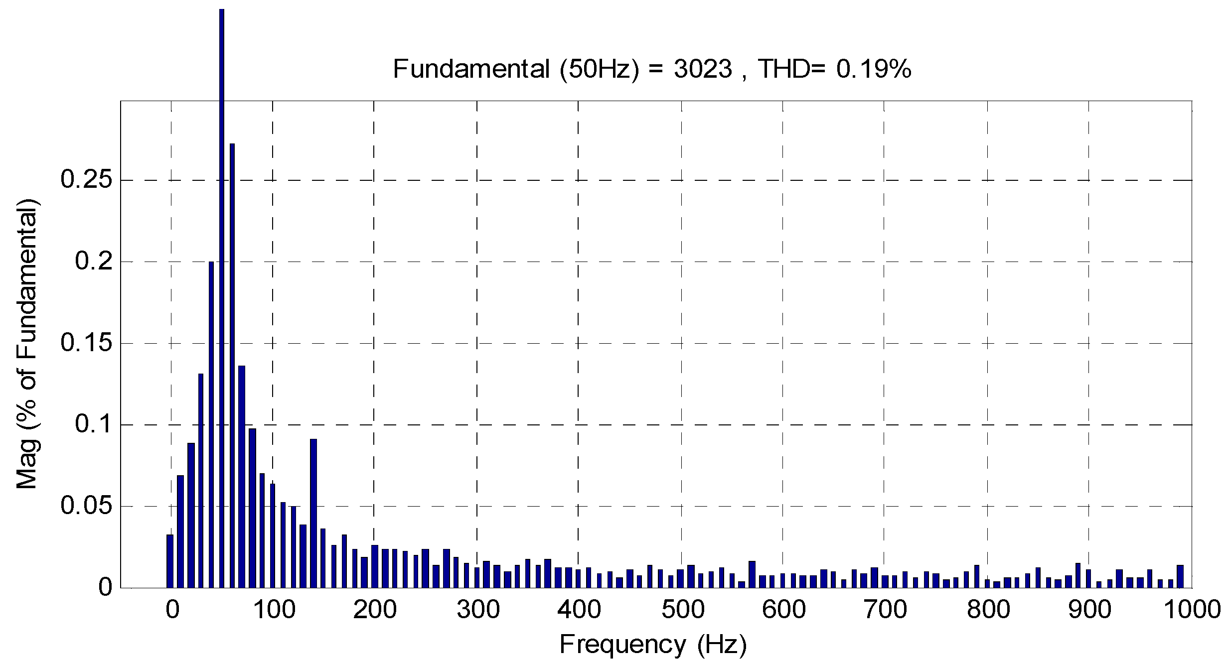
| Proposed strategy | DFTC-TOSM | 0.19 |
| Criteria | Control | |
|---|---|---|
| DFTC-PI | DFTC-TOSMC | |
| Dynamic response (s) | Medium | Fast |
| Settling time (ms) | High | Medium |
| Overshoot (%) | Remarkable ≈ 22% | Neglected near ≈ 1.5% |
| Torque and flux tracking | Good | Excellent |
| Sensitivity to parameter change | High | Medium |
| Rise Time (s) | High | Medium |
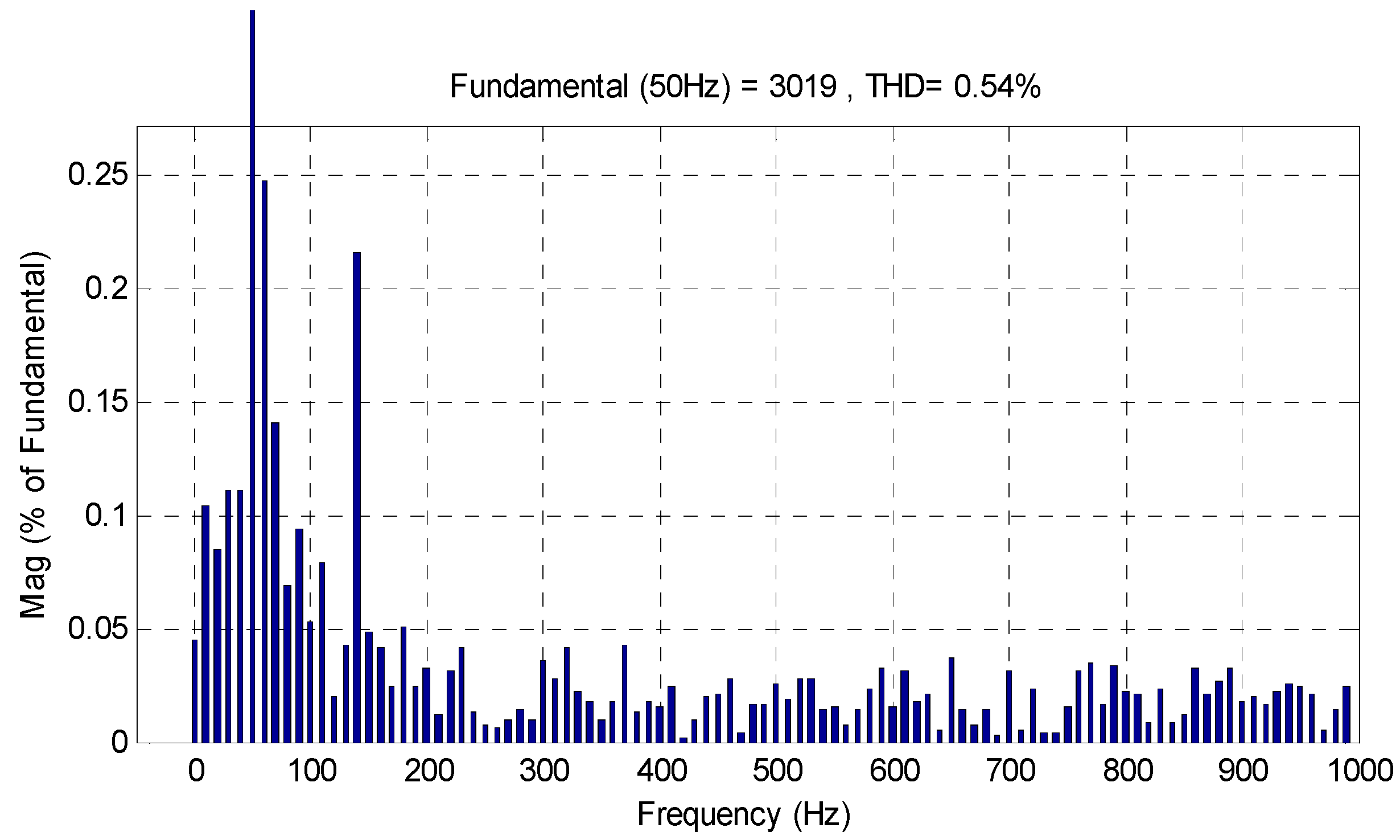
| THD (%) | 0.54 | 0.19 |
| Simplicity of converter and filter design | Simple | Simple |
| Torque: ripple (N.m) | Around 500 | Around 60 |
| Simplicity of calculations | Simple | Simple |
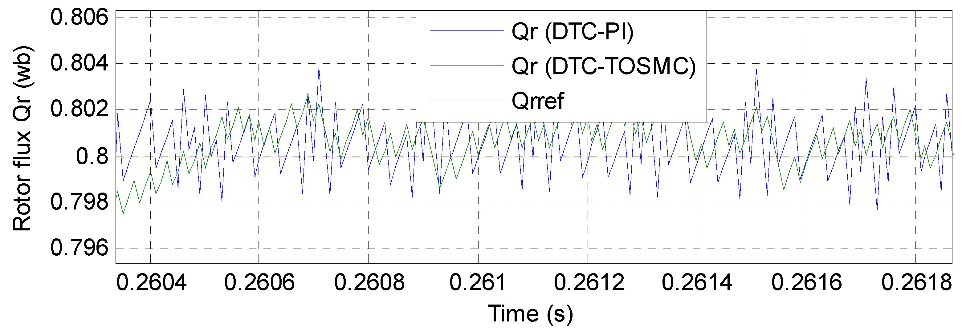
| Rotor flux: ripple (wb) | Around 0.006 | Around 0.004 |
| Improvement of transient performance | Good | Excellent |
| Reduce torque and flux ripples | Acceptable | Excellent |
| Quality of stator current | Acceptable | Excellent |
Publisher’s Note: MDPI stays neutral with regard to jurisdictional claims in published maps and institutional affiliations. |
© 2021 by the authors. Licensee MDPI, Basel, Switzerland. This article is an open access article distributed under the terms and conditions of the Creative Commons Attribution (CC BY) license (https://creativecommons.org/licenses/by/4.0/).
Share and Cite
Benbouhenni, H.; Bizon, N. Improved Rotor Flux and Torque Control Based on the Third-Order Sliding Mode Scheme Applied to the Asynchronous Generator for the Single-Rotor Wind Turbine. Mathematics 2021, 9, 2297. https://doi.org/10.3390/math9182297
Benbouhenni H, Bizon N. Improved Rotor Flux and Torque Control Based on the Third-Order Sliding Mode Scheme Applied to the Asynchronous Generator for the Single-Rotor Wind Turbine. Mathematics. 2021; 9(18):2297. https://doi.org/10.3390/math9182297
Chicago/Turabian StyleBenbouhenni, Habib, and Nicu Bizon. 2021. "Improved Rotor Flux and Torque Control Based on the Third-Order Sliding Mode Scheme Applied to the Asynchronous Generator for the Single-Rotor Wind Turbine" Mathematics 9, no. 18: 2297. https://doi.org/10.3390/math9182297
APA StyleBenbouhenni, H., & Bizon, N. (2021). Improved Rotor Flux and Torque Control Based on the Third-Order Sliding Mode Scheme Applied to the Asynchronous Generator for the Single-Rotor Wind Turbine. Mathematics, 9(18), 2297. https://doi.org/10.3390/math9182297