Article

Intelligent Automation System on a Single-Board Computer Platform for the Agro-Industrial Sector

by
Elena Butsenko
1,*,
Aleksandr Kurdyumov
1,2 and
Aleksandr Semin
1,2
1
Department of Business Informatics, Institute of Management and IT, Ural State University of Economics, 620144 Ekaterinburg, Russia
2
Department of Competition Law and Antimonopoly Regulation, Institute of Finance and Law, Ural State University of Economics, 620144 Ekaterinburg, Russia
*
Author to whom correspondence should be addressed.
Mathematics 2020, 8(9), 1480; https://doi.org/10.3390/math8091480
Submission received: 20 July 2020 / Revised: 25 August 2020 / Accepted: 28 August 2020 / Published: 2 September 2020
(This article belongs to the Special Issue Mathematical and Instrumental Methods in the Digital Economy)

Abstract

:
The latest technologies in agribusiness include a range of IT solutions that reduce manual intervention with the top priority tasks to improve, develop, and implement projects based on smart agriculture, which operates on the principles of automation and robotization of production. The aim of the study is to develop a system of automated control of business processes for an agricultural enterprise. The system allows for remote collection and processing of data on technical and economic performance of the farming enterprise. It proves to be a low-cost solution due to the use of affordable and available equipment. When designing the system, the authors described its back end, as well as the connectivity architecture between sensors and modules on one side, and the microcontroller on the other. The paper features modules for monitoring and controlling electrical energy consumption, lighting, temperature, and humidity written in C ++ programming language. Test modules that were controlled by the Arduino microcontroller were analyzed. Further development of the system may involve devising and introducing IoT technologies based on the use of various architectural platforms for practical application.

1. Introduction

Outbreaks of massive plant diseases annually cause enormous damage to agricultural industry worldwide. Despite the successes achieved in recent years in crop production of a significant number of crops, the risk of epidemics not only has not decreased, but has got significantly higher. This fact can be explained by a number of objective reasons:
  • the widespread introduction of new intensive agricultural technologies;
  • global climate change;
  • an increase in international trade and exchange of crop products; and,
  • a decrease in the biodiversity of plant communities (cenoses), etc.
Under the new land-use conditions, existing methods to monitor crop cultivation, forecast and control epidemics require significant adjustments. Modern systems of prevention and protection against epidemics must be integrated with world achievements in the fields of phytopathology, plant and pathogen genetics, ecology, phytosanitary toxicology, mathematics, computer science, engineering, etc.
Digital innovations and technologies may be part of the solution. The so-called ‘Fourth Industrial Revolution’ (Industry 4.0)1 is seeing several sectors rapidly transformed by ‘disruptive’ digital technologies such as the blockchain, Internet of things, artificial intelligence and immersive reality. In the agriculture and food sector, the spread of mobile technologies, remote-sensing services, and distributed computing are already improving smallholders’ access to information, inputs, market, finance, and training [1,2]. Digital technologies are creating new opportunities to integrate smallholders in a digitally-driven agrifood system [3,4,5,6].
The advent of digitalization and automation is of benefit to agriculture; however, it also adds a new risk factor for the business: the use of such technologies increases the threat of production shutdowns and downtime in case of unstable or insufficient energy supply, which can result in heavy financial losses. Therefore, reliable energy control systems in agriculture are just as important as fertilizers, feed, watering, and timely harvesting.
The automation of a large number of agricultural processes is made possible due to the ability of joining objects into a single network; data exchange and management based on the Internet of things; improved computer performance; development of software and cloud platforms; digital modelling of the entire production cycle and interconnected parts of the value chain; and, the ability to take emergency measures to prevent losses when meeting a threat, to calculate future productivity, production costs, and profits.
Intensive digitalization and use of the Internet of things in agriculture helps to transform the industry, which is less affected by the IT, into a high-tech business through the rapid growth of productivity and reduction of non-productive costs, which are the attributes of Agriculture 4.0 [7]. Information comes from various devices located in the field, on the farm, from sensors, agricultural machinery, weather stations, drones, satellites, external systems, partner platforms, and suppliers. General data from various participants in the production chain, collected in one place, allows the user to receive information, find patterns, create added value for every participant involved, apply modern scientific methods of data processing (data science) and use them to make the right decisions that minimize risks and improve both the manufacturers’ business and customer experience.
The development and implementation of smart farming systems have been addressed in a large number of scientific papers [8,9,10,11,12,13,14,15,16,17]. Oliver et al. described a general monitoring framework based on the IoT, which was applied to and tested on vineyards and implied processing and control of a range of weather and soil parameters. It aims to anticipate certain diseases common for vineyards, particularly those with weather conditions to be critical predictors of outbreaks [8,9,10,11,12].
Bacco et al. [13] provided an overview of the latest research into solutions for smart agriculture. They focus on the EU territory, identify threats and concerns resulting from the digitization of agriculture, and look at existing and upcoming solutions to overcome those barriers.
In [14], the authors explained the capabilities and features of mySense, a generic platform to quickly create monitoring applications for precision viticulture. It builds over a four-layer technological structure: sensors and actuators, WSN (Wireless Sensor Network) and gateways, web/cloud, and user applications. Fog computing is utilized at the WSN and gateways level to run local tasks and generate real-time alerts. The mySense environment was used in a vineyard to study the disease dynamics in the context of prevailing microclimates.
The ambient temperature is a crucial climate condition that influences equipment productivity; it also affects many organizational decisions on farms concerning, for example, greenhouse management and irrigation scheduling. In [15], the authors demonstrated how the CPU temperature of affordable single-board computers and a microcontroller may be utilized to predict outdoor temperature. The CPU temperature is first transmitted to an on-farm Edge cloud. A combination of calibration smoothing, via Single Spectrum Analysis (SSA) and linear regression, are then used to predict the temperature at the device. Edge computing ensures the required low latency. Such a method makes it possible to utilize the pre-existing sensing infrastructure.
Key supporting technologies include RFID and blockchains [16]. The potential of blockchains for the use in IoT is widely recognized [17]. The paper’s findings are also based on research that was conducted in [18,19,20,21] and are further development of the ideas presented in [22,23].
Thus, the development of intelligent automation systems represents a pressing challenge for agriculture, which requires modern tools to deal with. IoT is a combination of frameworks, sensors, and software. The value of the article lies in the design and development of such an automated control system that will represent an inextricable combination of equipment, programming, data, and control by obtaining valuable information using existing technologies, transferring it between devices and independently managing them. Nowadays, human life is becoming easier and more convenient; therefore, there is a need for an automated system to reduce human effort in daily activities as electronics and technology advance. The system controls enterprise’s facilities using sensors to measure key indicators to ease human efforts. It is designed to continuously monitor technical condition of the premises used for agricultural purposes. For instance, if the light level is low, Arduino switches on additional lamps to ensure sufficient illumination. When the system detects enough moisture, the water pump will automatically shut off. Every time the pump is turned on or off, a message is sent to the user via the GSM module, updating the status of the water pump and humidity. The system also monitors the status of the facilities, checks for the presence of unauthorized persons, and, if necessary, reports this. It helps take measures to save enterprise’s resources, such as water, electricity, human resources, etc.
The purpose of the study is to design and set up an intelligent automation system to manage business processes of an agricultural enterprise. The set purpose entails attaining the following objectives:
  • to define the key principles running the system of automated equipment control being developed to monitor and manage business processes in the enterprise;
  • to determine the set of microcontrollers, the basic components of the monitoring hardware;
  • to identify sensors, modules and expansion cards compatible with the selected microcontrollers;
  • to consider using a computing server designed to process the data transmitted from the microcontroller;
  • to identify the main electronic and electrical processes supporting the enterprise’s activities; and,
  • to specify the shortcomings of the developed system and offer ways to tackle them.

2. Materials and Methods

Modern agriculture and agribusiness impose high requirements on the organization of the enterprises’ processes, from the choice of technology for growing crops to the safety and control of auxiliary equipment. The reliability requirements for complex control systems for farming enterprises are getting stricter. As a result, the engineering equipment of agricultural enterprises is steadily becoming more complicated, and the number of devices that are involved in the shared environment is growing.
The development of an integrated agricultural production system involves the use of IT-technologies, tools for automated equipment control, and sensor technology. It is based on the methods of designing automated enterprise control systems, IoT technologies, decision support methods, robotics and automation, satellite navigation technologies, etc. [24,25,26,27,28,29,30,31,32,33,34,35].
We shall define the basic procedures of the system to be developed (Figure 1) that are necessary to achieve the above objectives. These include the following:
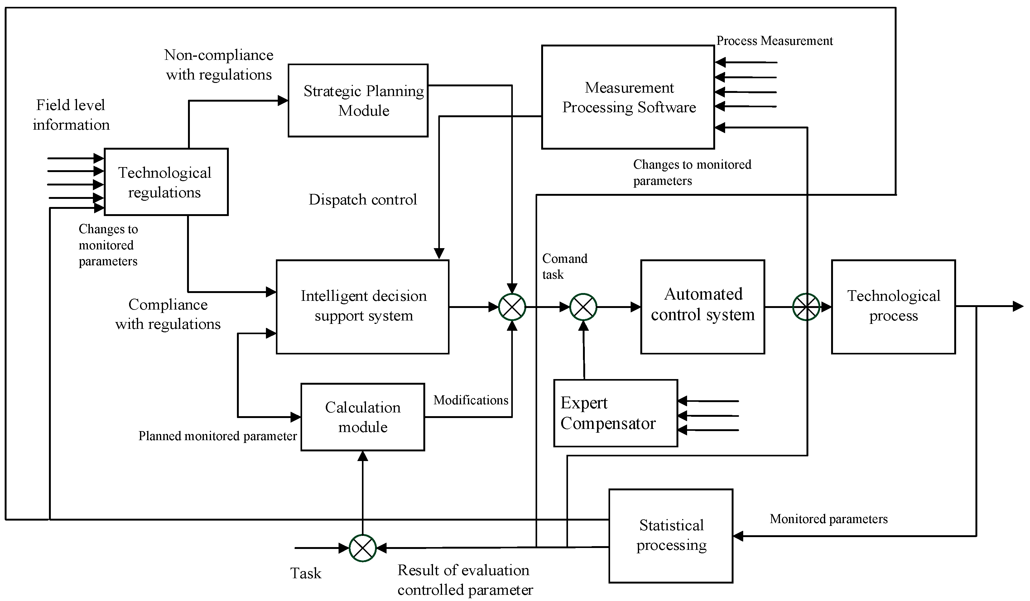
  • statistical processing and regulation (stabilization) of the controlled parameters of a technological process;
  • management of operations or devices;
  • software logical control;
  • optimization of control over transient modes or individual stages of the process;
  • general adaptive process control;
  • immediate correction of daily and shift targets to achieve strategic goals;
  • direct and indirect measurement (collection, primary processing and storage of information);
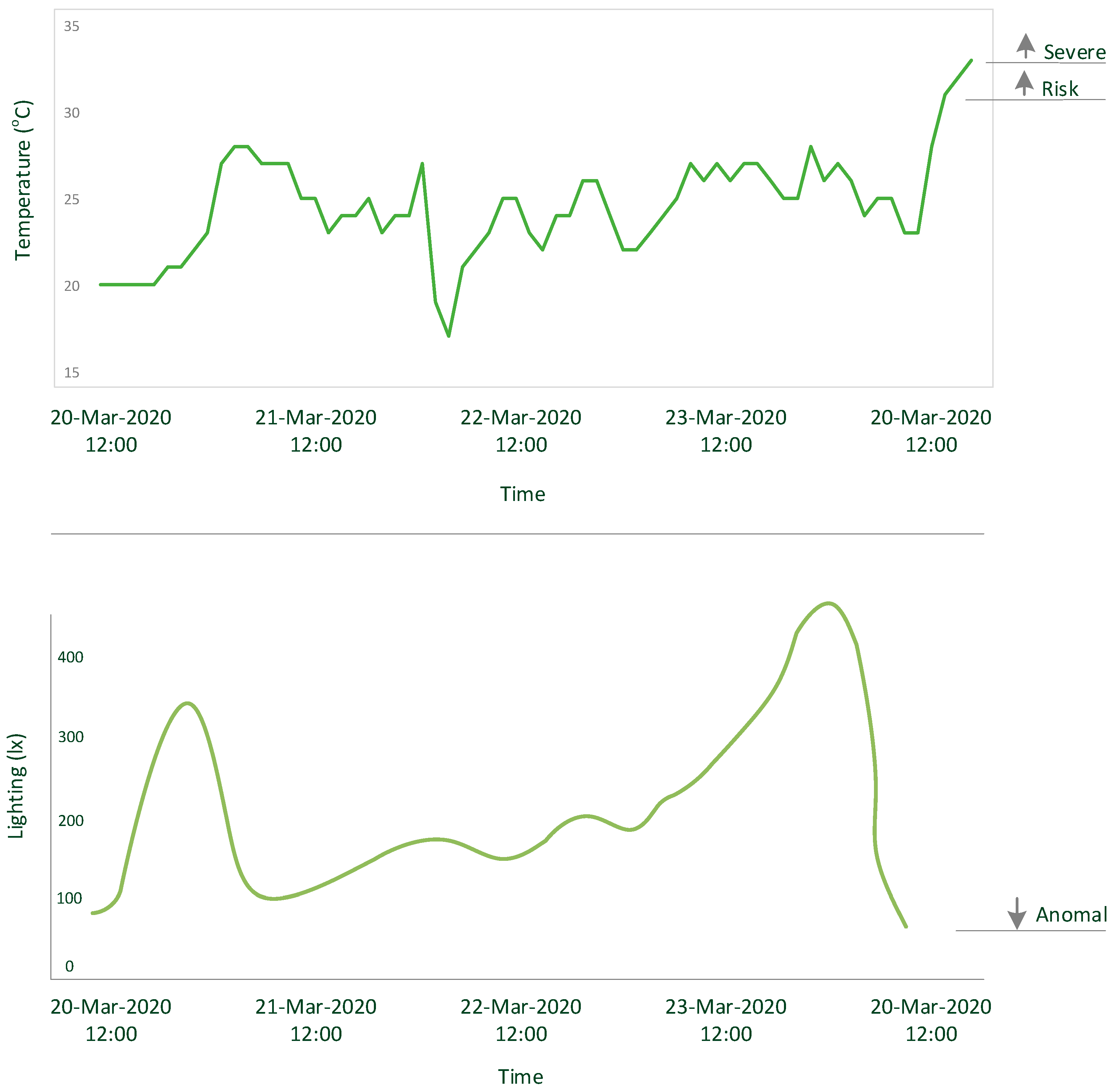
  • control, warning about, and registration of deviations in the parameters of the technological process;
  • calculation of technical, economic and operational indicators of the technological process and equipment;
  • analysis of the processing units’ safety/failure lock operation; and,
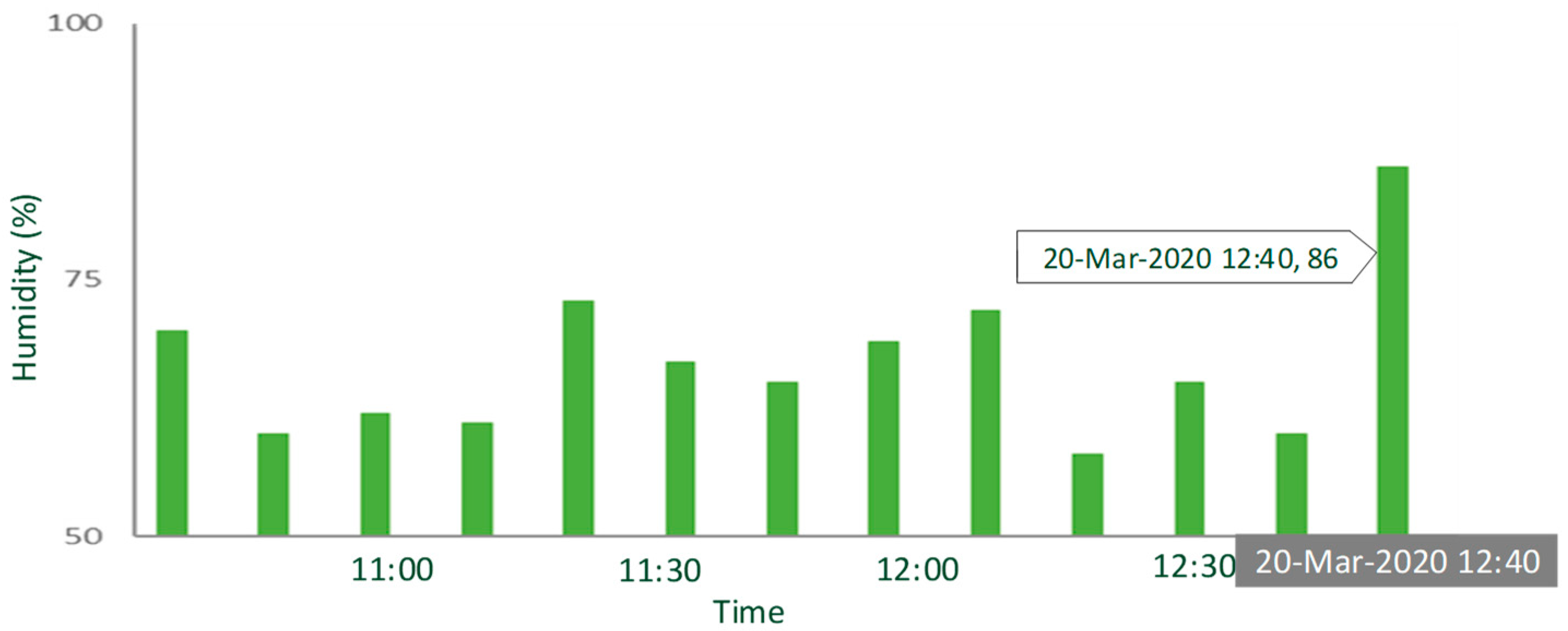
  • prompt display of the requested information on the technological process.
The main functions of the intelligent automation system for an agricultural enterprise include:
  • automatic dispatching of technological equipment parameters (levels, pressures, phase separation levels, temperatures and costs of technological devices);
  • comparison of the measured values of the technological parameters with the set values and generation of control, warning and alarm signals;
  • display of the process flow in the form of indicators;
  • timing of the main technological parameters; and,
  • automated operational control of gate and globe valves from the remote control of the automated workplace of the operator or technologist.
Consider the basic principles of the intelligent automation system of an agricultural enterprise. Every modern facility, to a greater or lesser extent, owns a large number of equipment functioning, providing and creating a fully-fledged working environment. The convenience of managing these systems, their integration with each other, the ability to work together seamlessly, thereby individually increasing the functionality of each of them makes it possible to call such a farm smart or intelligent. The intelligent automation system optimally maintains a constant microclimate, while keeping the desired temperature, humidity, and lighting.
An intelligent automated control system for a farming enterprise is based on IoT technologies and constantly monitors all of the engineering systems and prevents emergencies. It ensures obtaining the data on the status of the system as a whole, as well as its transmission at any distance. The type of automated control systems under consideration is an intelligent automation system for managing engineering systems of a modern farming enterprise.
The Agricultural Automation Intelligent System (AAIS; British company Raspberry Pi, Ekaterinburg, Russia) provides a centralized intelligent control mechanism for office, production, auxiliary and utility rooms, workshops, warehouses, tank farms, and garages. The application of the system allows for the enterprise to set the parameters of the customizable environment, gain access to the status information from all of its subsystems, and manage them. The AAIS interface is based on interaction with touch video panels that show a plan of any room or surrounding area and display images from CCTV video cameras.
When running the selected scenario, the system can be quickly adjusted by changing the parameters of the devices. Additional settings allow the system to turn off or put unused rooms (climate warm chambers, air conditioners, etc.) into power saving mode, and activates the perimeter security mode. This ensures the economy and safe mode of operation of the equipment. The system notifies of emergency situations through the built-in speaker systems or, if assigned, calls the special services—the emergency service, the police, or the fire department.
Table 1 presents the basic principles of the intelligent automation system for an agricultural enterprise.
We shall consider the Arduino microcontroller as the most affordable tool for creating an intelligent automation system for an agricultural enterprise. There are several reasons behind choosing this microcontroller. Arduino has long been showing itself as a serious development tool. In small farms, there is no point in using such systems, as, for example, Cropio (an automated satellite monitoring system for farmland, New Science Technologies, New York, NY, USA) [21], due to their complexity and high price. There is a large number of free libraries available for this microcontroller, with which the necessary control functions can be programmed. Moreover, there are many compatible sensors and other electronic components on the market that cover various needs and requirements of customers.
The microcontroller development environment contains two blocks: void setup () {} and void loop () {}. The setup block is executed at the startup. The loop block defines execution of a function in a loop. The user needs to preset the necessary parameters for the board and ports before loading the program. When loading the program, the Bootloader loads the program code without using any additional hardware. The Bootloader stays active for several seconds after rebooting the platform and loading the program into the microcontroller and flashes pin 13 LED when invoked. The microcontroller monitors serial bus and displays the data sent to the platform. The Serial.begin function sets the serial data transmission rate.

3. Results

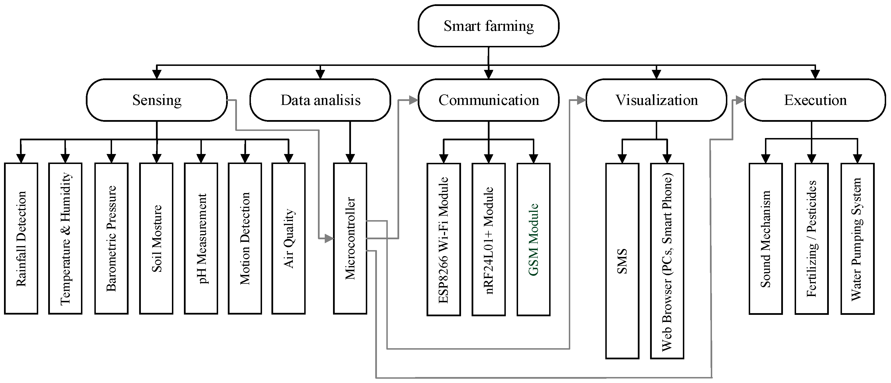
3.1. System Structure

An intelligent automation system for an agricultural enterprise based on the IoT consists of five interconnected subsystems: sensing [24], data analysis [25], communication [26], visualization [27], and execution. The sensing subsystem is interconnected with the data analysis subsystem, where the raw data from each sensor is processed and analyzed individually with various algorithms implemented in the microcontroller for the visualization and execution subsystem [28]. The process of visualizing the sensor data directly depends on the communication subsystem, since access to these data via a mobile phone, smartphone, or PC requires establishing a connection to the modules of the communication subsystem. If the user (farm worker) wants to visualize the data through a web browser, then the IoT ESP8266 module is required [29]. If one wants to receive a short message on a mobile phone, the data will be visualized through the Arduino “Sketch” IDE serial monitor, and will depend on the nRF24L01 module [30] and so on. The system is capable of making decisions and executing them based on the sensor data used by the execution subsystem, which are the main subject of the presented system. Figure 2 shows the structure of an intelligent automation system for an agricultural enterprise.

3.2. Connecting Sensors and Modules to the Arduino Microcontroller

We shall define the general requirements for the device under development. Firstly, we will identify its power consumption and remotely measure the number of kilowatts that the electricity meter shows, as well as collect the data on the current load on the circuit. The electricity meter generates pulses in accordance with the amount of electrical energy consumed. The pulses are shown by the LED indicator. The faster it flashes, the more kW the system uses.
The meter pulse rate (A) on the front panel of the device shows the number of pulses per 1 kW·h. The meter used to collect the data has A = 1000. Hence:
(a) with each pulse, the meter records the consumption equal to 1/1000 of 1 kW·h. The quotient of the number of pulses after the load is applied divided by the pulse rate gives the amount of consumed electrical energy (kW·h); and,
(b) since the indicator changes its blink speed, it is possible to derive the relationship between the power (kW) and the meter’s pulse length, which will allow obtaining the data on power or current.
A photoresistor is used to read the electricity meter.
Next, we shall turn to creating a device that can read the data from the meter and allows the user to remotely obtain the number of consumed kilowatts, as well as the current load. When connecting the photoresistor to the microcontroller, it is necessary to take into account that the voltage of 0–5 volts will be registered at the output of the photoresistor circuit. It must be converted to a specific number for the microcontroller program to work. The photoresistor circuit represents a voltage divider, the upper leg of which will vary, depending on the intensity of light incident on the face of the photoresistor. The voltage from the lower leg is fed to the analog input, which converts it into a number from 0 to 1024.
When working on the program code, it is important to keep in mind the processor sophistication, its ability to work correctly with floating point numbers, and the probability of performing complex calculations on the server. The flashes of the meter pulses at the high load are quite short and frequent, therefore the microcontroller must constantly and very quickly read the photoresistor, which makes any additional load with numerous calculations undesirable. The AAIS uses a variable that shows which input the photoresistor is connected to. The data from the photoresistor are constantly read and written to this variable in the loop block. The number of flashes is recorded, depending on whether there was a signal or not. As soon as it reaches the pulse rate, the amount of energy consumed becomes equal to 1 kW, the pulse counter gets reset, i.e., for the selected counter 1 kW is equal to 1000 pulses. The obtained value is transmitted to the server for processing and logging.
The program code for calculating energy consumption is as follows:
if ((val>500) and (impulse= =false)) {
impulse = true;
}
if ((val<500) and (impulse==true)) {
imp++;
}
if (imp==schetchik) {
imp=0;//upon reaching A, reset the pulses
kilovat++;
}
impulse=false;
The processing power of the microcontroller is sufficient enough to process these values in the normal mode of operation. However, for better performance, it is highly recommended that you avoid excessive load on the microcontroller, as it has to accurately record the number and calculate the length of flashes that may occur a number of times per second. The more accurate computation will reduce the measurement error.
In addition to determining the number of kilowatts, it is important to know the current load. To do this, use the millis () function, which starts the stopwatch. The pulse length can be calculated as a difference between the on and off times of the counter. The program code for recording the time for determining the load is given below:
Void loop () {
Val = analogRead (photoPin);
time = millis ();
if ((val>500) and (impulse= =false)) {
  t1 = time;
  impulse = true;}
if ((val<500) and (impulse==true)) {
  t2 = time;
  voltageTime = t2-t1;//sending the pulse length to the server
  imp++;//sending the number of pulses to the server
  if (imp==schetchik) {
   imp=0;//reset the pulse counter
   kilowatt++;//sending the number of kilowatts to the server
  }
impulse=false;
voltageTime = 0;
t1 = 0; t2 = 0;//resetting the variables denoting the on/off times
}
Each electrical appliance in each room is plugged in one-by-one at the minimum load on the electrical grid to record their power consumption. Based on this, it is determined which appliances can be operated at the moment. The register of the plugged-in and switched on appliances can be accessed via the web server; therefore, idle equipment can be identified and turned off in order to reduce the total power consumption.
In addition to monitoring the energy consumption, the AAIS measures and captures the ambient temperature both indoors and outdoors with the temperature and relative humidity sensor DHT11 doing the former. The recorded data can be seen on the LCD 1602 screen and are sent to the server to collect statistics. While the recorded data are sent to the server, the temperature can be displayed on the screen to ease access to it without using the website. To do this, add the LiquidCrystal.h library with the #include statement. The LiquidCrystal.lcd () function initializes the display and sets the pins used to connect to the LCD. The display dimensions can be set with the lcd.begin (x, y) function in the setup block.
The following program code can be applied to read the temperature sensor:
#include “DHT.h”
#define DHTPIN 3
#define DHTTYPE DHT11
DHT dht (DHTPIN, DHTTYPE);
void setup ()
{
}
void loop ()
{
int h = dht.readHumidity ();
int t = dht.readTemperature ();
}
The functions added to the system include displaying the current temperature value on the screen; its minimum and maximum values; and, the humidity value. The function changing the screen every three seconds was added to fit the output on the display. It clears the screen and prints the characters on it again.
The first screen shows the current temperature value, the second one displays its minimum and maximum values, and the third one is used for indicating humidity. Such a sequence is programmed with the millis () function, which starts the counter and counts 3 s, and then changes the screen, depending on which one was displayed. The order in which the screens are shown is set using the d1, d2, and d3 Boolean variables denoting the current temperature, the minimum and maximum temperatures, and humidity, respectively. The initial values for d1, d2, and d3 are set to true, false, and false, respectively. This means that, when the program starts, the display shows the current temperature.
When the text is displayed, the time t1 equal to the current time of the counter is recorded. As soon as the difference between the time of the counter and the recorded t1 value exceeds 3000 ms (three seconds), the display clears. t1 changes again to the current time of the counter, after which the d1, d2, and d3 values become false, true, and false. This activates the screen with the minimum and maximum temperatures.
The screen showing humidity operates similarly. Thus, there is a successive cycle of the screens on the display that change every three seconds. This allows the user to monitor the temperature and relative humidity in the room without having to access the web interface storing the data:
if (pr= =false) {min=t; max=t; pr=true;}
if (t<min) min=t;
if (t>max) max=t;
if ((time-t1>3000) and (d1= =true) and (d2= =false) and (d3= =false)) {
lcd.clear ();
lcd.setCursor (0,0);
lcd.print (“Temperature “); lcd.print (t); lcd.print (“ C”);
t1=0; t1=time;
d1=false; d2=true;
Serial.println (“display 1”);
}
if ((time-t1>3000) and (d1= =false) and (d2= =true) and (d3= =false)) {
lcd.clear ();
lcd.setCursor (0,0);
lcd.print (“Min “); lcd.print (min); lcd.print (“ C ”);
lcd.print (“Max “); lcd.print (max); lcd.print (“ C”);
t1=0; t1=time;
d1=false; d2=true;
Serial.println (“display 2”);
}
if ((time-t1>3000) and (d1= =false) and (d2= =false) and (d3= =true)) {
lcd.clear ();
lcd.setCursor (0,0);
lcd.print (“Humidity “); lcd.print (h);
lcd.print (“Max “); lcd.print (max); lcd.print (“ C”);
t1=0; t1=time;
d3=false; d1=true;
Serial.println (“display 3”);
}
The AAIS also contains a module that was developed to automatically notify of trespassing on the farming enterprise property. The alert message can be delivered via any convenient communication channel (loudspeaker, telephone, multimedia screens, etc.). To obtain the status of the doors (open/closed), the system uses the reed switch module. To carefully manage the microcontrollers’ idle capacities, the reed switch is connected to the microcontroller recording the temperature and humidity data, and sends the readings to the display via the unused digital output.
There is no need to add any libraries in this case. To receive the data from the reed switch module, the digital output on the microcontroller must be set. This information is then read in the loop block. The result is transmitted to the server, which transfers the data on whether the door is open or closed through the communication channel, and the door status is shown on the display:
void loop () {
val = digitalRead (gerkon);
lcd.setCursor (0,1);
  if (val==1) {
  lcd.print (“Open “);
  }
  if (val==0) {
   lcd.print (“Close “);
  }
}
Thus, you can be completely sure that no one enters the room unnoticed. You can also find out how many times and at what time exactly the front door opened and closed, and determine how long it was open.
The system has motion sensors installed to automatically turn the light on when the personnel enter in order to reduce the electrical energy consumption. When using an infrared motion sensor, the movement of inanimate objects does not affect the automatic switching on of light. The sensor reads the thermal radiation from the object and sends 0 or 1 to the microcontroller based on the change in the position of the thermal radiation. If there is no movement, the signal is zero, otherwise—1. If the object in the room stops moving, 0 is transmitted, and the system immediately switches the light off. In order to prevent the light from turning off for some time, you can set the on time using the millis () function and stop the system from turning the light off for a certain time, even if there is no movement. Moreover, if the object moves during this time, the timer gets reset and the countdown starts over.
To implement automatic light switching, the program code below can be applied:
void loop ()
{ time = millis ();
int val = digitalRead (Dvig);
if (val ==0) {
t2 = time;
long t = 0;
t = t2-t1;
Serial.print (“t2-t1= “);
Serial.println (t);
  if ((t>5000) {
  digitalWrite (Relay, HIGH); //relay off
Serial.print (“t1= “);
Serial.println (t1);
  t1=0;
  }
}
if (val==1) {
digitalWrite (Relay, LOW);//relay on
t1=time;
}
t2=0;
}
Figure 3 and Figure 4 present examples of program performance. Figure 3 demonstrates the results of monitoring humidity in the room where crops are grown. At 12:40, the permissible humidity level was exceeded and the microcontroller initiated a command to stop the water supply to the sprayer. Figure 4 shows the report on illumination and temperature levels’ change to ensure effective plant growing. It can be seen that, when the set values are exceeded, the users are notified and the indicators are adjusted using the necessary equipment (setting the intensity of main and supplemental lighting, fan speed, etc.).

4. Discussion

In the course of assembling and testing the modules under the control of the Arduino microcontroller, the following limitations were identified and need to be taken into account before installing the system on the premises for regular operation.
  • The first limitation consists in a small amount of memory. 32 and 64 KB of memory is enough for writing small programs. For a significant number of operations, an external memory module is required.
  • Poor computational performance of the microcontroller. This microcontroller incorrectly processes real numbers, as shown by the analysis of its operation as an automatic reader of the electricity meter. It may lose the remainder of the quotient or reset the variables when dividing them. To avoid this, in some cases it is necessary to send the data to an external server for processing, or use additional processing devices, such as, for example, the Raspberry Pi 2 Model B. It has a processing unit, RAM, HDMI, USB, Ethernet, analog audio and video outputs. It also has 40 general-purpose I/O pins that can be used to connect peripherals to interact with actuators, such as contact relays, servomotors, and any sensors.
  • Unlogged failures during the program operation. A failure can only be detected if something stops working. However, even if the failure is detected, the system will not report how many times it happened before. In order to record the number of program crashes, you can use EEPROM (Electrically Erasable Programmable Read-Only Memory) special memory cells. These will prevent overloading the microcontroller.

5. Conclusions

The AAIS performance was tested in a specific environment that was related to the agricultural enterprise, but not in the enterprise itself. The results obtained during its operation were almost equivalent to this environment. Actual results can be obtained by implementing the system in the agricultural enterprise, which is a lengthy process and requires tremendous effort. However, the theoretical tests suggest that the performance of the system is adequate, and it will give more accurate results when implemented in the agricultural enterprise.
This paper describes such an element of the agricultural complex digitalization as smart farming. The developed intelligent automation system for the agricultural enterprise uses the IoT technology to control electrical energy consumption, temperature, and humidity.
The main advantages of using the system are as follows:
  • The system operates on the platform of single-board computers based on the Arduino microcontroller.
  • The system represents a simple and convenient tool for managing the enterprise’s business processes.
  • The use of the developed software for intelligent systems in agriculture significantly reduces labor costs, eliminates human errors, and speeds up the processing of information, even in large agricultural enterprises.
Thus, the system turns out to be low-cost, more energy efficient, and easier to use when compared to its counterparts (for example, Cropio [21]).
The abovementioned advantages can increase the profitability and competitiveness of the farming enterprise on the global market and ensure its sustainable and economically sound development, which is a top priority task for any business [37].
Some elements of the artificial intelligence and machine learning technologies can be added to the AAIS to improve the performance of the developed software [38,39]. The use of advanced and powerful microcontrollers, such as the Raspberry Pi 4 [40], STM32 (Nucleo Series) [41], etc., will make the farming system even more efficient and accurate.

Author Contributions

Conceptualization, E.B., A.K. and A.S.; methodology, E.B.; software, E.B.; validation, E.B.; formal analysis, E.B.; investigation, E.B.; resources, A.K.; data curation, E.B.; writing—original draft preparation, E.B.; writing—review and editing, E.B.; visualization, E.B.; supervision, A.K.; project administration, A.S. and A.K.; funding acquisition, A.K. All authors have read and agreed to the published version of the manuscript.

Funding

This research was funded by Russian Foundation for Basic Research, grant number 19-010-00886 «The comprehensive economic and legal study of improving the competitiveness of the agro-industrial complex of the Russian Federation in the context of the development and integration of information digital systems».

Conflicts of Interest

The authors declare no conflict of interest.

References

  1. UN DESA. International Migration Report. Department of Economic and Social Affairs. 2019, p. 38. Available online: https://www.un.org/en/development/desa/population/migration/publications/migrationreport/docs/MigrationReport2019_Highlights.pdf (accessed on 20 March 2020).
  2. OECD. Organisation for Economic Co-operation and Development. 2019. Available online: https://www.oecd-ilibrary.org/agriculture-and-food/agricultural-policy-monitoring-and-evaluation_22217371 (accessed on 20 March 2020).
  3. Lowder, S.K.; Skoet, J.; Raney, T. The Number, Size, and Distribution of Farms, Smallholder Farms, and Family Farms Worldwide; Food and Agriculture Organization of the United Nations: Rome, Italy, 2016. [Google Scholar] [CrossRef] [Green Version]
  4. ILOSTAT. Free and Open Access to Labour Statistics. 2019. Available online: https://ilostat.ilo.org/data/ (accessed on 20 March 2020).
  5. FAO. Food and Agriculture Organization of the United Nations Publications Catalogue. 2019, p. 140. Available online: http://www.fao.org/home/digital-reports/en/ (accessed on 20 March 2020).
  6. USAID. United States Agency International Development Fiscal Year 2018 Agency Financial Report. 2018; p. 184. Available online: https://www.usaid.gov/sites/default/files/documents/1868/USAIDFY2018AFR_508R.pdf (accessed on 20 March 2020).
  7. Trendov, N.M.; Varas, S.; Zeng, M. Digital Technologies in Agriculture and Rural Areas–Briefing Paper. 2019. Available online: http://www.fao.org/3/ca4887en/ca4887en.pdf (accessed on 2 September 2019).
  8. Oliver, S.T.; González-Pérez, A.; Guijarro, J.H. An IoT proposal for monitoring vineyards called SEnviro for agriculture. In Proceedings of the ACM 8th International Conference on the Internet of Things (IOT ’18), Santa Barbara, CA, USA, 15–18 October 2018; pp. 1–4. [Google Scholar]
  9. Oliver, S.T.; González-Pérez, A.; Guijarro, J.H. A Comprehensive IoT Node Proposal Using Open Hardware. A Smart Farming Use Case to Monitor Vineyards. Electronics 2018, 7, 419. [Google Scholar]
  10. Oliver, S.T.; González-Pérez, A.; Guijarro, J.H. Adapting Models to Warn Fungal Diseases in Vineyards Using In-Field Internet of Things (IoT) Nodes. Sustainability 2019, 11, 416. [Google Scholar] [CrossRef] [Green Version]
  11. Oliver, S.T.; González-Pérez, A.; Guijarro, J.H. An IoT Platform Based on Microservices and Serverless Paradigms for Smart Farming Purposes. Sensors 2020, 20, 2418. [Google Scholar]
  12. Oliver, S.T.; Torres-Sospedra, J.; Belmonte, Ó.; Zarazaga-Soria, F.J.; González-Pérez, A.; Guijarro, J.H. Development of an open sensorized platform in a smart agriculture context: A vineyard support system for monitoring mildew disease. Sustain. Comput. Inform. Syst. 2019. [Google Scholar] [CrossRef]
  13. Bacco, M.; Barsocchi, P.; Ferro, E.; Gotta, A.; Ruggeri, M. The Digitisation of Agriculture: A Survey of Research Activities on Smart Farming. Array 2019, 3–4, 100009. [Google Scholar] [CrossRef]
  14. Morais, R.; Silva, N.; Mendes, J.; Adao, T.; Padua, L.; Lopez-Riquelme, J.; Pavon-Pulido, N.; Sousa, J.J.; Peresmy, E. Sense: A comprehensive data management environment to improve precision agriculture practices. Comput. Electron. Agric. 2019, 162, 882–894. [Google Scholar] [CrossRef]
  15. Krintz, C.; Wolski, R.; Golubovic, N.; Bakir, F. Estimating outdoor temperature from CPU temperature for IoT applications in agriculture. In Proceedings of the 8th International Conference on the Internet of Things (IOT’18), ACM, Santa Barbara, CA, USA, 15–18 October 2018; p. 11. [Google Scholar]
  16. Kamilaris, A.; Fonts, A.; Prenafeta-Boldύ, F.X. The rise of blockchain technology in agriculture and food supply chains. Trends Food Sci. Technol. 2019, 91, 640–652. [Google Scholar] [CrossRef] [Green Version]
  17. Zhao, G.; Liu, S.; Lopez, C.; Lu, H.; Elgueta, S.; Chen, H.; Boshkoska, B.M. Blockchain technology in agri-food value chain management: A synthesis of applications, challenges and future research directions. Comput. Ind. 2019, 109, 83–99. [Google Scholar] [CrossRef]
  18. Fedorenko, V.F.; Goltyapin, V.Y.; Kolchin, L.M. Intellectual Systems in Agriculture: Scientific-Analytic Review; Federal State Scientific Institution, Rosinformagrotekh Publisher: Moscow, Russia, 2017; 156p. [Google Scholar]
  19. Leea, W.S.; Alchanatisb, V.; Yangc, C.; Hirafuji, M.; Moshoue, D.; Lif, C. Sensing Technologies for Precision Specialty Crop Production Computers and Electronics in Agriculture. Comput. Electron. Agric. 2010, 74, 2–33. [Google Scholar] [CrossRef]
  20. Shamshiri, R.R.; Weltzien, C.; Hameed, I.A.; Yule, I.J.; Grift, T.E.; Balasundram, S.K.; Pitonakova, L.; Ahmad, D.; Chowdhary, G. Research and development in agricultural robotics: A perspective of digital farming. Int. J. Agric. Biol. Eng. 2018, 11, 1–14. [Google Scholar] [CrossRef]
  21. Charania, I. Smart Farming: Agriculture’s Shift from a Labor Intensive to Technology Native Industry; Elsevier: Amsterdam, The Netherlands, 2020. [Google Scholar]
  22. Maslakov, V.; Butsenko, E.; Kurdyumov, A. Developing an IoT system for an agricultural enterprise on a single-board computer platform. In Proceedings of the International Scientific and Practical Conference “Digitization of Agriculture-Development Strategy” (ISPC 2019), June 2019; pp. 174–178. [Google Scholar] [CrossRef] [Green Version]
  23. Butsenko, E.; Kurdyumov, A. Smart farming on a single-board computer platform. Models Syst. Netw. Econ. Technol. Eng. Soc. 2019, 1, 29. Available online: https://cyberleninka.ru/article/n/umnoe-zemledelie-na-platforme-odnoplatnyh-kompyuterov (accessed on 20 January 2020).
  24. Kaewmard, N.; Saiyod, S. Sensor data collection and irrigation control on vegetable crop using smart phone and wireless sensor networks for smart farm. In Proceedings of the 2014 IEEE Conference on Wireless Sensors (ICWiSE), Subang, Malaysia, 26–28 October 2014; pp. 106–112. [Google Scholar] [CrossRef]
  25. Li, D.; Zheng, Y.; Zhao, W. Fault Analysis System for Agricultural Machinery Based on Big Data. IEEE Access 2019, 7, 99136–99151. [Google Scholar] [CrossRef]
  26. Wang, P. Introduction: Advances in IoT research and applications. Inf. Syst. Front. 2015, 17, 239–241. [Google Scholar] [CrossRef] [Green Version]
  27. Dachyar, M. Knowledge growth and development: Internet of things (IoT) research, 2006–2018. Helion 2019, 5, 1–14. [Google Scholar] [CrossRef] [PubMed] [Green Version]
  28. Ashifuddin Mondal, M.; Rehena, Z. IoT Based Intelligent Agriculture Field Monitoring System. In Proceedings of the 2018 8th International Conference on Cloud Computing, Data Science & Engineering (Confluence), Noida, India, 11–12 January 2018; pp. 625–629. [Google Scholar] [CrossRef]
  29. Mesquita, J.; Guimarães, D.; Pereira, C.; Santos, F.; Almeida, L. Assessing the ESP8266 WiFi module for the Internet of Things. In Proceedings of the 2018 IEEE 23rd International Conference on Emerging Technologies and Factory Automation (ETFA), Turin, Italy, 4–7 September 2018; pp. 784–791. [Google Scholar] [CrossRef]
  30. Wu, G.; Tao, J.; Xu, X. Application and Design of Wireless Community Alarm System Based on nRF24L01 Module. In Proceedings of the 2019 Chinese Control and Decision Conference (CCDC), Nanchang, China, 3–5 June 2019; pp. 1991–1995. [Google Scholar] [CrossRef]
  31. Rose, D.C.; Sutherland, W.J.; Parker, C.; Lobley, M.; Winter, M.; Morris, C.; Twining, S.; Ffoulkes, C.; Amano, T.; Dicks, L.V. Decision support tools for agriculture: Towards effective design and delivery. Agric. Syst. 2016, 149, 165–174. [Google Scholar] [CrossRef] [Green Version]
  32. Granell, C.; Kamilaris, A.; Kotsev, A.; Ostermann, F.O.; Trilles, S. Internet of Things. In Manual of Digital Earth; Springer: Singapore, 2020; pp. 387–423. [Google Scholar]
  33. El-kadi, H.; Samir, H.; Rezki, Z. Modelling and Reliability Analysis of Multi-source Renewable Energy Systems Using Deterministic and Stochastic Petri Net. Open Autom. Control Syst. J. 2018, 10, 25–40. [Google Scholar] [CrossRef]
  34. Iliushko, V.; Retha, E.; Dierks, S.; Marques, P. Automatic Control Systems; Marques Aviation: London, UK, 2016; 275p. [Google Scholar]
  35. Singh, S. Agri-Info: Cloud Based Autonomic System for Delivering Agriculture as a Service; Elsevier: Amsterdam, The Netherlands, 2020. [Google Scholar]
  36. Zhou, Y. Design of Miniature Unmanned Helicopter Attitude Monitoring System Based on nRF24L01+. In Proceedings of the 2013 Third International Conference on Instrumentation, Measurement, Computer, Communication and Control, Shenyang, China, 21–23 September 2014. [Google Scholar]
  37. Semin, A.; Kibirov, A.; Rassukhanov, U. Problems and Main Mechanisms to Increase Investment Attractiveness of Agricultural Production. Eur. Res. Stud. J. 2018, 21, 378–400. [Google Scholar] [CrossRef]
  38. Martino, B.D. Internet of Things Reference Architectures, Security and Interoperability: A Survey; Elsevier: Amsterdam, The Netherlands, 2018; pp. 99–112. [Google Scholar]
  39. Coquin, D. Assistance via IoT Networking Cameras and Evidence Theory for 3D Object Instance Recognition: Application for the NAO Humanoid Robot; Elsevier: Amsterdam, The Netherlands, 2020. [Google Scholar]
  40. Kamath, R. Raspberry Pi as Visual Sensor Nodes in Precision Agriculture: A Study. IEEE Access 2019, 7, 45110–45122. [Google Scholar] [CrossRef]
  41. Chaber, P. Fast Analytical Model Predictive Controllers and Their Implementation for STM32 ARM Microcontroller. IEEE Trans. Ind. Inform. 2019, 15, 4580–4590. [Google Scholar] [CrossRef]
Figure 1. General block diagram of an intelligent automation system for an agricultural enterprise.
Mathematics 08 01480 g001
Figure 2. The structure of an intelligent automation system for an agricultural enterprise.
Mathematics 08 01480 g002
Figure 3. Monitoring room humidity over a period of time.
Mathematics 08 01480 g003
Figure 4. Controlling room lighting and temperature.
Mathematics 08 01480 g004
Table 1. Composition and principles of operation of an intelligent automation system.
No.ObjectDescription of Operation
1MicrocontrollersAre programmed on the board using a development environment and programming language based on C/C ++
2SensorsMeasure the necessary physical quantities or react to physical phenomena and transmit this information via electrical signals
2.1Pyroelectric sensorIt captures the movement of warm objects. The output from the sensor is a binary digital signal. If there is no movement, the signal contact = 0. When the motion is detected, the signal contact = 1
2.2Infrared rangefinderIs used for navigation and avoiding obstacles
2.3Ultrasonic rangefinderIs used to determine the distance to the object by generating sound pulses propagated by the sound wave to and from the object
3Function modulesPerform designated functions
3.1MT-16S2H LCD displayIs used to display text messages
3.2Reed switch moduleThe reed switch contains flexible metal ferromagnetic contacts. They overlap in length, but are a small distance from each other. These are used for switching (closing or opening the circuit). When the magnet is brought near to the reed switch, the contacts close (or open). It can trigger a siren if used as a position control sensor or after lifting an object
3.3Load control moduleThe maximum switching voltage is AC 250 V or DC 30 V. The rated switching current is 10 A. The relay contact group consists of three contacts, which makes it possible not only to close the circuit, but also to break it. The LED indicator used to control the operation of the module is connected to the system without any additional strapping. It has galvanic isolation and, therefore, is well protected from high-voltage power supplies
3.4Data transfer modulesEstablish wired and wireless connection between microcontrollers. Wireless communication modules (nRF24L01 + transceivers) [36] wirelessly scan the sensors and send commands to the executive devices of the system. These are the basic components of a radio control system for devices and other modules
4Ethernet Shield Expansion CardActs as a networking device to access other devices. It is based on the Wiznet W5100 chip, which supports both the TCP and UDP protocols
5Web serverIs designed to remotely monitor and control microcontrollers of the system with connected sensors and modules. It is responsible for receiving and processing website requests from clients. The most widespread web servers include Apache, IIS and iPlanet server. They support a large number of modules, utilities, and add-ons. For a small agricultural enterprise intranet, the Internet Information Server (IIS) is the best option. It can be easily deployed and configured, integrated with access controls, uses Performance Monitor (a performance monitoring tool for system settings control), etc. IIS is noted for its high-speed performance. Its components support the HTTP, HTTPS, FTP, NNTP, SMTP, and POP3 protocols
6ResistorsAre used to change the resistance of the electric current. Their resistance varies within 10% depending on the temperature coefficient of resistance
7CapacitorIs a device that stores electrical energy in electrical circuits. In the AAIS, capacitors are used as isolation elements, where it is necessary to block the flow of direct current, but let the alternating current pass
8TransistorSeveral transistors are connected in series to obtain increased power (the Darlington configuration)

