Abstract
We review the immersed boundary (IB) method in order to investigate the fluid-structure interaction problems governed by the Navier–Stokes equation. The configuration is described by the Lagrangian variables, and the velocity and pressure of the fluid are defined in Cartesian coordinates. The interaction between two different coordinates is involved in a discrete Dirac-delta function. We describe the IB method and its numerical implementation. Standard numerical simulations are performed in order to show the effect of the parameters and discrete Dirac-delta functions. Simulations of flow around a cylinder and movement of Caenorhabditis elegans are introduced as rigid and flexible boundary problems, respectively. Furthermore, we provide the MATLAB codes for our simulation.
1. Introduction
Fluid–structure interaction is widely observed in various fields [1,2,3,4,5]. However, simulating fluid-structure interaction is a challenge problem in mathematics, because of its boundary layer transition. The immersed boundary (IB) method was originally proposed by Peskin in 1977 in order to model flow patterns around heart valves [6,7]. It is widely used for simulating fluid-structure interactions, such as turbulent flow [8,9], biomembrane [10,11], glioma invasion [12], and swimming eel [13]. In the IB method, the Eulerian variables are defined based on a fixed Cartesian coordinate system, and the Lagrangian variables move freely through the fixed Cartesian coordinates. Their interaction is expressed by a discrete Dirac-delta function. The advantages of the IB method are its simplicity and efficiency in handling complicated geometries without mesh regeneration.
In the original IB method, the massless boundary moves with the velocity of the ambient flow by the fluid force, and the density of the structure is spread out to the ambient flow in order to consider the inertia of the elastic structure [6]. The movement of the elastic boundary with mass can be easily simulated by the extension of the original IB method by Kim and Peskin, which is called the penalty IB method [14]. The penalty IB method has recently been extended to simulate the elastic boundary with mass [14] and the interaction between a rigid body and a surrounding fluid [15]. The numerical simulation with high Reynolds numbers is strictly limited when using the conventional IB method, because it is needed to capture the flow transition in a thin boundary layer at high Reynolds numbers. It can be resolved by refining the mesh grid locally [16,17] or imposing a velocity profile based on a wall model [18,19] at the cutting egde.
This paper briefly reviews the IB method and its numerical implementation. The derivation of the equation of motion for the IB method is quite intuitive; however, some issues remain regarding its implementation for beginners, such as the choice of delta functions and the effect of parameters. To resolve this, the actual program code is provided with the corresponding numerical simulations. Moreover, a practical example is introduced in order to explain the modeling of biological phenomena using the IB method.
The remainder of this paper is organized, as follows. We describe the mathematical formulations for the IB method in Section 2. Section 3 presents the discretization of the IB method. The numerical results are presented to show the effect of the Reynolds number and discrete Dirac-delta function in Section 4. Finally, Section 5 presents the conclusion. Furthermore, we provide the MATLAB code for the numerical implementation from the corresponding author’s webpage and its structure can be found in Appendix A.
2. Mathematical Formulations
Let be the position of the Lagrangian points with label s, describing the configuration in a two-dimensional space at particular time t. If we assume that the evolution of the configuration is determined by the (elastic) energy according to the functional , the functional is expressed in the following form:
where ℘ is a variation symbol that distinguishes the symbol from the Dirac-delta function . Taking the Fréchet derivative of E at , we can define the force density that is generated by the material as follows:
The elastic energy functional is given by
where is the stiffness coefficient and is the -norm. Subsequently, we obtain
Thus, the elastic force density can be rewritten as
where
is the tension of the configuration and
is the unit tangent vector to the configuration. This is the only formulation for the elastic force, and it can be modified by adding other energy functional to Equation (3) in order to consider the corresponding force.
Let be the velocity at the position and time t. Subsequently, we can define the velocity of the configuration , as follows:
where denotes the two-dimensional Dirac-delta function . Note that the material derivative of is defined as
and it implies that
Conversely, the system would naturally evolve to minimize the time integration of the difference between the kinetic and potential energy functionals:
where is the variational derivative of the configuration at position and time t, which implies . Because the expression contains both Lagrangian and Eulerian variables, we should eliminate the Lagrangian variables by defining the fluid mass density and fluid force density , as follows:
For simplicity, we assume a constant mass density, which is, and .
The equations of fluid motion are governed by the Navier–Stokes (NS) equation, as follows:
where is the pressure, is the viscosity, and is the square domain. Let and be the Reynolds and Weber numbers with the characteristic velocity and length , respectively. Subsequently, the non-dimensionalized version of Equations (14) and (15) can be expressed, as follows:
3. Discretization
Various numerical schemes have been developed to solve the NS equation. In this study, we employ the implicit scheme, as follows [20]:
Here, is the discrete gradient operator using the central difference and is the discrete Laplacian operator defined as
For the convection term , we use the skew symmetry, as follows:
Other terms are computed in a similar manner.
Applying the projection method [21], we split Equation (18) into two equations with the temporal velocity , as follows:
Taking the divergence operator into Equation (24), the Poisson equation for the pressure is derived by Equation (19), as follows:
Equation (23) can be solved directly, because it has an explicit formulation, and the fast Fourier transformation is used to solve Equations (24) and (25). The details can be found in [20]. Here, the fluid forcing term is given by
where is the set of indices for the Lagrangian points, is the discrete Dirac-delta function, which was discussed in the later section, and is the step size of the label of the configuration. Here, the discrete force density for the structure is defined by
where is the discrete differential operator with respect to s. Finally, the discretization of the transport equation for IB is given, as follows:
where is the set of Eulerian points.
4. Numerical Results
4.1. Code and Simulation
In this section, we discuss the MATLAB code of the IB method for solving a moving boundary problem with a simple and basic example. The code updates the fluid velocity and boundary position from the given values and .
To explain how to obtain the updated boundary position, we first set a domain of fixed Cartesian coordinates for a fluid and let the IB structure on the fixed domain. Here, the following ellipse is chosen for the initial condition of the boundary:
where L is the length of the domain.
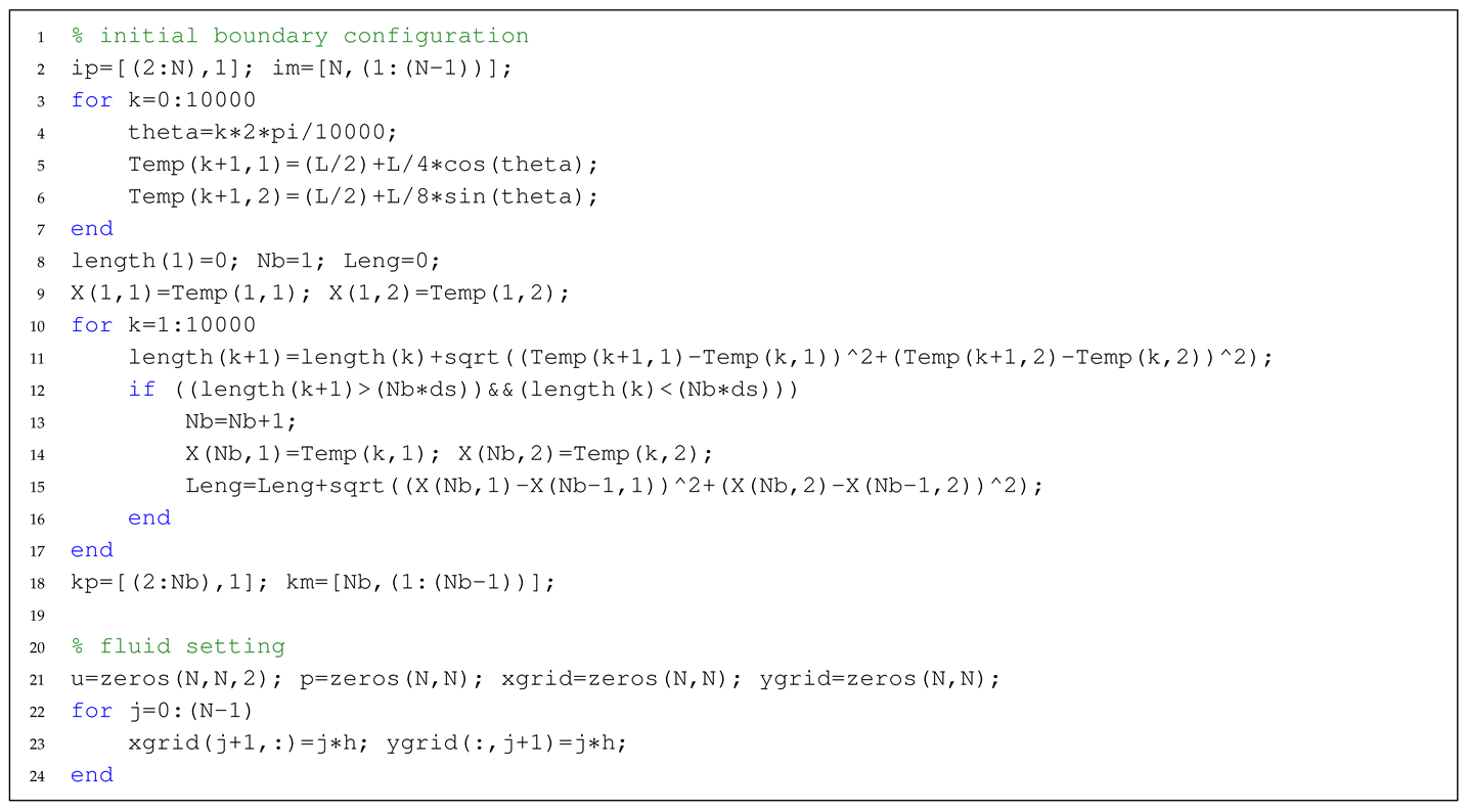
Next, the elastic boundary force density is evaluated from the IB structure. It can be obtained from a minus gradient of the elastic energy functional with respect to X. An elastic energy function can be classified based on three types of contributions: stretching, bending, and tether energies. In the example, the force is only generated from the stretching energy with a zero rest length.

Using the evaluated boundary force density in the previous step, we spread out the boundary force density to a fluid force density while using the Dirac-delta function. This is one of the key steps for the fluid-structure interaction in the IB method. There are some choices of the Dirac-delta function, and its details will be discussed in the next section.

The next step is to update the fluid velocity by solving the NS equation while using the spread fluid force density on the fluid (fixed) domain. Subsequently, the Dirac-delta function is used again to obtain the velocity on the elastic IB boundary.

Finally, we can obtain the updated boundary position by solving the transport equation. See the Appendix for a detailed code of the elastic membrane relaxation in viscous fluids.

Figure 1 shows the vorticity and pressure contours around the damped vibration elastic body after code execution. Note that the vorticity is a physical quantity that represents a local circulation in the fluid and it is defined as a flow rate rotation, and the pressure difference is derived from the boundary force density. If the reader uses the code to simulate other problems, then it is important to modify the initial boundary and force density generation. We will introduce the simulation of the rigid and flexible boundary problems in Section 4.3 and Section 4.4, respectively.
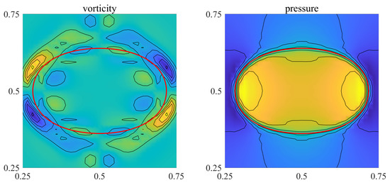
Figure 1.
Vorticity (left) and pressure (right) contours around the damped vibration elastic body.
4.2. Discrete Delta Function
The Dirac-delta function, , plays an important role in the interaction of fluids and boundaries in the IB method. In Equations (8), (12), and (13) are used for interpolation or spread out of the values between fluids and boundaries. The function assumes the form , where satisfies the following properties [22]:
- is continuous,
- for ,
- for all r,
- for all r, and
- for all r.
There are some common choices for the discrete delta functions or regular functions , such as 2-point, 4-point, 4-point cosine, and 6-point functions. Figure 2 shows the profile of the various regular functions, that form the delta functions, . Among the choices, the only regular function , which satisfies all of the above five conditions, is defined, as follows:
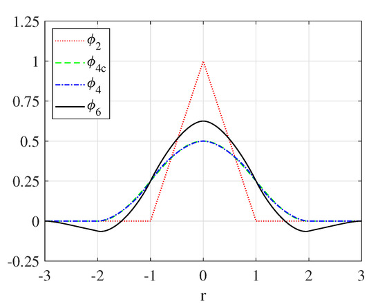
Figure 2.
Various regular functions that form the delta functions .
Other regular functions can be obtained by changing the support size or adding/deleting conditions. For example, the four-point cosine approximation does not satisfy the second moment condition (5th condition in the list). The detailed formulas mentioned above can be found in [23].
We constructed a dumbbell-shaped boundary, as shown in the upper left panel of Figure 3, to investigate how the selection of the delta function affects the simulation. The distance between boundaries is equal to at . The initial boundary comprises a single closed curve and it is given a stretching force. Thus, with time, the boundary must change to a circular shape.
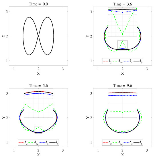
Figure 3.
Simulation results based on selection of the delta function.
Figure 3 shows the simulation results of the selection of the delta function in the IB method. When using , it is the most affected by close distance, and when using , it is the least affected. The delta function has wider support than . However, the actual impact thickness shows that function is narrower than function from the simulation results.
Figure 4 shows the area within the boundary over time in each case that is covered in Figure 3. In general, the traditional IB method has a disadvantage of causing volume loss within boundaries. The use of the function in this simulation result appears to be the most vulnerable to volume retention within boundaries.
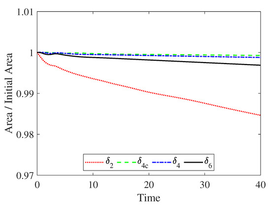
Figure 4.
The area within the boundary over time in each case covered in Figure 3.
4.3. Effect of the Reynolds Number
Next, we apply the IB method for modeling flows around fixed rigid bodies. A simple approach for implementing a fixed rigid body using the traditional IB method is to place the target point() at the desired location and attach the boundary() whlie using a rigid spring. Here, the tethered force density is defined by
where is the stiffness constant.
The flow around obstacles, such as circular or square cylinders, has been extensively studied for Newtonian fluids [2,5,24,25,26]. Flows around these obstacles exhibit a variety of phenomena, such as boundary layer separation, vortex shading, lift, and drag forces. In general, the flow around a circular cylinder can be categorized by the range of the Reynolds number, as follows:
- , regime of unseparated flow,
- , a fixed pair of Föppl vortices in the wake of the cylinder,
- , periodic the von Karman vortex street, and
- , transition to turbulence in vortex street.
Figure 5 shows vorticity and streamline distribution for fluid flow across 2D cylinders, depending on the various Reynolds numbers. The flow around the circular cylinder according to the Reynolds number is consistent with the literature. We can see that vortex shading is produced behind the obstacle when and 200. Moreover, the length of the vortex shedding and distance between Karman vortices in the square cylinder appears longer than in the circular cylinder. Figure 6 shows the drag coefficients of circular and square cylinders as a function of the Reynolds numbers. The drag coefficient is a dimensionless number used to quantify the drag of an object in a fluid environment. The higher the Reynolds number, the smaller the drag coefficient. The drag coefficient is higher in the square cylinder than in the circular cylinder.
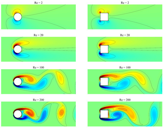
Figure 5.
Vorticity and streamline distribution of fluid flow across 2D circular (left panels) and square (right panels) cylinders at depending on the various Reynolds numbers.
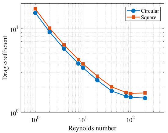
Figure 6.
Drag coefficients of circular and square cylinders as a function of the Reynolds number.
Table 1 lists the drag coefficients and lift coefficients calculated for and 200. The value of the present result is higher than that of the references. This is attributed to constraints caused by treating rigid bodies while using the IB method. In the traditional IB method, the stiffness constant was set high to indicate a fixed rigid body in response to the flow. This makes numerical calculations unstable and makes it difficult to calculate the correct coefficients. Despite these limitations, simulating the rigid body using traditional IB methods has the advantage of dealing with complex boundaries. Figure 7 shows the flow around the obstacle, which includes not only circular and rectangular cylinders, but also star-shaped boundaries of complex boundaries. Looking at the flow around the star-shaped boundary, we can see that the pointed part of the shape affects the flow. In other words, it is also sufficient to use traditional IB methods to identify the behavioral characteristics of flows around complex boundaries.

Table 1.
Lift and drag coefficients of flow around a circular cylinder at and 200.
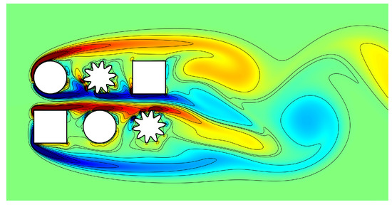
Figure 7.
Flow simulation between various shapes, such as circles, squares, and star shapes at .
4.4. Biological Problem
Simulations of eel, sperm, bacteria, and other swimmers have been developed whlie using the IB method. In this section, we discuss the simulation results of various motions of the C. elegans and present a simulation of the free swimming using the randomwalk. C. elegans is a nematode of approximately 1 mm length that lives in temperate soil environments. To simulate the movement of the C. elegans, we used one line representing the C. elegans body as the center skeleton. Two forces that produce movement are applied to the center line; the stretching force and bending force. The stretching force is used for representing the unextended body; the bending force is used for representing the body shape. The stretching energy is shown in Equation (3), and the bending energy is shown, as follows:
where is the bending coefficient, is the unit normal vector to the body, and is the reference wave curvature. Various movements may be indicated, depending on the construction of . For example, to simulate a forward nematode, is organized as a traveling wave, as follows:
where is the wave number with wavelength , A is the oscillation amplitude, and is the oscillation frequency.
Figure 8 shows the simulation results for various movements (forwarding motion, backward motion, rest, and coil turn) of C. elegans according to the configuration. The left side of each panel represents the wave shape, and the right side represents the snapshot of C. elegans over time. Unlike in the top panels, the wave shape in the bottom panels is consistently applied over time. In-silico model of C. elegans combines each of these motions to move forward or rotate to the desired point. Note that changes in wave curvature alone lead to different movements.
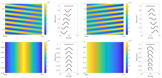
Figure 8.
Simulation results for various movements of elagans according to the configuration. left-up: forwarding motion, right-up: backward motion, left-bottom: rest, and right-bottom: coil turn.
Randomwalk is a process that comprises a sequence of steps determined by chance. As shown in Figure 8, we simulated the randomwalk with the combination of each motion of C. elegans. Figure 9 shows the results of the randomwalk. Each motion consists of forward, rest, and coil turns, assuming a motion decision cycle of s. In each panel, ’S’ represents the starting point and ’E’ represents the ending point. In the top panel, it can be seen that the progress of C. elegans changes direction immediately after the coil turn. In the lower panels, the trajectory of motion was compared according to the ratio of determination of moving (forward) and stop (rest and coil turn) motion. Each simulation was performed for 20 s and the ratio of rest and coil turns in stop motion set equal, which is . Table 2 shows the moving distance and turn angle according to the ratio of the moving and stop motions. We can notice that a higher rate of moving motion yields larger displacement, and a higher ratio of stop motion causes more rotation.
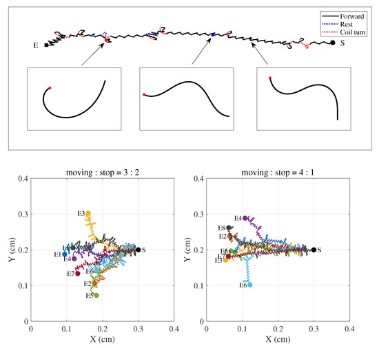
Figure 9.
(top panel) Trajectory of C. elegans randomwalk and snapshot of forward(black), rest(blue), and coil turn(red) and (bottom panels) comparison of trajectories according to the ratio of moving and stop motion. In each panel, ’S’ and ’E’ represent the starting and the ending points, respectively.

Table 2.
Moving distance and turn angle according to the ratio of moving and stop motion.
5. Conclusions
In this paper, we briefly reviewed the IB method in order to investigate the fluid-structure interaction problems that are governed by the NS equation and provided the MATLAB codes for numerical implementation. The essence of the IB method is its simplicity to represent the (not limited to simple) interaction between fluid and structure by coupling Eulerian and Lagrangian representations. The equations of motion and discretization were described in the IB framework. The computational results are shown as an example to facilitate the understanding of the IB method, including the choice of discrete delta functions, the effect of the Reynolds number, and the application for the biological problem. In a typical example or the volume conservation, it was shown that the choice of the discrete delta function affects the dynamics. The error estimation of regular functions is a topic that has been actively discussed. We also showed that the use of the conventional IB method is sufficient to identify the behavioral characteristics of flows around complex boundaries by considering the effect of the Reynolds number. Nevertheless, it remains an open problem to simulate flows around complex boundaries in the case of high Reynolds numbers.
Author Contributions
All authors, who contributed equally, read and approved the final manuscript. All authors have read and agreed to the published version of the manuscript.
Funding
W.L. was supported by the National Institute for Mathematical Sciences (NIMS) grant funded by the Korea government (No. NIMS-B20900000). S.L. was supported by the National Research Foundation of Korea (NRF) grant funded by the Korea government (MSIP) (No. 2020R1A2C1A01100114).
Acknowledgments
Many of the computations were performed using computing facilities at the National Institute for Mathematical Sciences (NFEC-2019-06-256100, NFEC-2012-03-158057). The authors also wish to thank the reviewers for the constructive and helpful comments on the revision of this article.
Conflicts of Interest
The authors declare no conflict of interest.
Abbreviations
The following abbreviations are used in this manuscript:
| IB | immersed boundary |
| NS | Navier–Stokes |
Appendix A. Code Structure
The MATLAB codes for our simulations are available from the corresponding author’s webpage: https://sites.google.com/view/sglee/research.
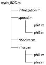
- main_IB2D.m: main code, including animation code for vorticity and pressure.
- initialization.m: setting parameters, including the domain and grid sizes, Reynolds and Weber numbers, and the initial boundary configuration
- spread.m: spreading out the boundary force density to the fluid force density using the Dirac-delta function
- NSsolver.m: updating the fluid velocity and pressure by using fast Fourier transformation
- Interp.m: getting the velocity on the elastic IB boundary from the fluid velocity
- phi1.m: setting the Dirac-delta function along the x-direction
- phi2.m: setting the Dirac-delta function along the y-direction
References
- Donea, J.; Giuliani, S.; Halleux, J. An arbitrary Lagrangian-Eulerian finite element method for transient dynamic fluid-structure interactions. Comput. Methods Appl. Mech. Eng. 1982, 33, 689–723. [Google Scholar] [CrossRef]
- Gibou, F.; Min, C. Efficient symmetric positive definite second-order accurate monolithic solver for fluid/solid interactions. J. Comput. Phys. 2012, 231, 3246–3263. [Google Scholar] [CrossRef]
- Jamalabadi, M. Analytical solution of sloshing in a cylindrical tank with an elastic cover. Mathematics 2019, 7, 1070. [Google Scholar] [CrossRef]
- Jamalabadi, M. Optimal design of isothermal sloshing vessels by entropy generation minimization method. Mathematics 2019, 7, 380. [Google Scholar] [CrossRef]
- Lee, S.; Li, Y.; Shin, J.; Kim, J. Phase-field simulations of crystal growth in a two-dimensional cavity flow. Comput. Phys. Commun. 2017, 216, 84–94. [Google Scholar] [CrossRef]
- Peskin, C.S. Flow patterns around heart valves: A numerical method. J. Comput. Phys. 1972, 10, 252–271. [Google Scholar] [CrossRef]
- Peskin, C.S. The immersed boundary method. Acta Numer. 2002, 11, 497–517. [Google Scholar] [CrossRef]
- Iaccarino, G.; Verzicco, R. Immersed boundary technique for turbulent flow simulations. Appl. Mech. Rev. 2003, 56, 331–347. [Google Scholar] [CrossRef]
- James, N.; Maitre, E.; Mortazavi, I. Immersed boundary methods for the numerical simulation of incompressible aerodynamics and fluid-structure interactions. Ann. Mathématiques Blaise Pascal 2013, 20, 139–173. [Google Scholar] [CrossRef][Green Version]
- Bächer, C.; Gekle, S. Computational modeling of active deformable membranes embedded in three-dimensional flows. Phys. Rev. E 2019, 99, 062418. [Google Scholar] [CrossRef]
- Lee, S. Mathematical model of contractile ring-driven cytokinesis in a three-dimensional domain. Bull. Math. Biol. 2018, 80, 583–597. [Google Scholar] [CrossRef] [PubMed]
- Lee, W.; Lim, S.; Kim, Y. The role of myosin II in glioma invasion: A mathematical model. PLoS ONE 2017, 12, e0171312. [Google Scholar] [CrossRef]
- Fauci, L.J. A computational model of the fluid dynamics of undulatory and flagellar swimming. Am. Zool. 1996, 26, 599–607. [Google Scholar] [CrossRef]
- Kim, Y.; Peskin, C.S. Penalty immersed boundary method for an elastic boundary with mass. Phys. Fluids 2007, 19, 053103. [Google Scholar] [CrossRef]
- Kim, Y.; Peskin, C.S. A penalty immersed boundary method for a rigid body in fluid. Phys. Fluids 2016, 28, 033603. [Google Scholar] [CrossRef]
- Lee, K.; Yang, K. Large Eddy simulation of turbulent flow past a circular cylinder in the subcritical and critical regimes. J. Mech. Sci. Technol. 2017, 31, 1729–1737. [Google Scholar] [CrossRef]
- Posa, A.; Vanella, M.; Balaras, E. An adaptive reconstruction for Lagrangian, direct-forcing, immersed-boundary methods. J. Comput. Phys. 2017, 351, 422–436. [Google Scholar] [CrossRef]
- Kang, S. An improved near-wall modelling for large-eddy simulation using immersed boundary methods. Int. J. Numer. Methods Fluids 2015, 78, 76–88. [Google Scholar] [CrossRef]
- Yang, X.; Sadique, J.; Mittal, R.; Meneveau, C. Integral wall model for large eddy simulations of wall-bounded turbulent flows. Phys. Fluids 2015, 27, 025112. [Google Scholar] [CrossRef]
- Peskin, C.S.; McQueen, D.M. Fluid Dynamics of the Heart and its Valves. In Case Studies in Mathematical Modeling: Ecology, Physiology, and Cell Biology; Othmer, H.G., Adler, F.R., Lewis, M.A., Dallon, J.C., Eds.; Prentice-Hall: Englewood Cliffs, NJ, USA, 1996. [Google Scholar]
- Chorin, A. Numerical solution of the Navier–Stokes equations. Math. Comput. 1968, 22, 745–762. [Google Scholar] [CrossRef]
- Liu, Y.; Mori, Y. Properties of discrete delta functions and local convergence of the immersed boundary method. SIAM J. Numer. Anal. 2012, 50, 2986–3015. [Google Scholar] [CrossRef]
- Stockie, J.M. Analysis and Computation of iMmersed Boundaries, with Application to Pulp Fibres. Ph.D. Thesis, University of British Columbia, Vancouver, BC, Canada, 1997. [Google Scholar]
- Braza, M.; Chassaing, P.; Minh, H.H. Numerical study and physical analysis of the pressure and velocity fields in the near wake of a circular cylinder. J. Fluid Mech. 1986, 165, 79–130. [Google Scholar] [CrossRef]
- Ding, H.; Shu, C.; Yeo, K.S.; Xu, D. Numerical simulation of flows around two circular cylinders by mesh-free least square-based finite difference methods. Int. J. Numer. Methods Fluids 2007, 53, 305–332. [Google Scholar] [CrossRef]
- Harichandan, A.B.; Roy, A. Numerical investigation of low Reynolds number flow past two and three circular cylinders using unstructured grid CFR scheme. Int. J. Heat Fluid Flow 2010, 31, 154–171. [Google Scholar] [CrossRef]
Publisher’s Note: MDPI stays neutral with regard to jurisdictional claims in published maps and institutional affiliations. |
© 2020 by the authors. Licensee MDPI, Basel, Switzerland. This article is an open access article distributed under the terms and conditions of the Creative Commons Attribution (CC BY) license (http://creativecommons.org/licenses/by/4.0/).