Article

Active Earth Pressure in Unsaturated Retaining Walls Influenced by Vegetation Root
1
School of Civil Engineering, Central South University, Changsha 410075, China
2
Shenzhen Municipal Group Co., Ltd., Shenzhen 518000, China
*
Author to whom correspondence should be addressed.
Mathematics 2026, 14(6), 995; https://doi.org/10.3390/math14060995
Submission received: 14 February 2026 / Revised: 10 March 2026 / Accepted: 12 March 2026 / Published: 15 March 2026
(This article belongs to the Special Issue Multiscale Modeling in Engineering and Mechanics, 2nd Edition)

Abstract

This study proposes a comprehensive framework, based on an upper-bound approach, for assessing how vegetation enhances wall stability through two primary mechanisms. The two mechanisms are reinforcement from root systems and hydrological reinforcement through transpiration-induced soil suction. Both contributions are integrated as additional internal energy dissipation terms within a logarithmic-spiral failure model. New expressions of earth pressure in unsaturated soil are derived, considering the influence of vegetation. The active earth pressure acting on the retaining wall is obtained using sequential quadratic programming. The proposed method is validated against classical non-vegetated solutions, confirming its accuracy. The results show that vegetation significantly reduces active earth pressure, with the extent of reduction depending on soil type, root distribution, and transpiration rate. In clay soils, both mechanical and hydrological effects are important, while in sandy soils, mechanical root reinforcement plays the dominant role. The effectiveness of vegetation is influenced by root depth, density, and diameter, with practical design insights provided through parametric charts. This work offers a theoretically consistent and design-oriented tool for evaluating vegetated retaining walls, emphasizing the coupled hydro-mechanical interactions between plants and soil.

1. Introduction

Safety modeling of limit analysis is widely used in infrastructure engineering, and the integration of plant roots into engineering soils represents a paradigm shift toward sustainable and eco-compatible infrastructure [1,2]. Live plants, through their root systems, have demonstrated a remarkable capacity to enhance the stability of soil structures such as natural slopes, landfill covers, embankments, and particularly retaining walls [3,4,5]. This bio-engineered approach leverages natural processes to create a living, self-repairing reinforcement system, offering a compelling alternative to conventional concrete and steel solutions. The hydro-mechanical interactions between roots and soil are now widely acknowledged as the cornerstone of this reinforcement mechanism [6,7]. Roots mechanically reinforce the soil matrix by mobilizing tensile resistance, generating interfacial friction along the root–soil interface, and providing deep anchorage, collectively imparting a significant apparent cohesion to the root-permeated soil [8,9]. Concurrently, through transpiration, plants extract water from the soil and increase matric suction, thereby providing substantial hydrological reinforcement in unsaturated soils [10,11].
Despite this well-established understanding, a significant disconnect persists. Empirical observations often do not align with the predictive capabilities of mainstream analytical design models. Conventional limit equilibrium methods and many numerical approaches often remain anchored in simplified assumptions, treating the mechanical and hydrological contributions of vegetation as merely additive components [12,13]. This simplification misrepresents the integrated nature of root–soil systems, where mechanical interlocking and hydrological pathways are intrinsically intertwined. The inherent spatial variability of root architecture—including hierarchical woody root systems with deep taproots, structural lateral roots, and extensive fine-root networks—exerts a profound influence on both stress redistribution and the development of suction fields [14,15]. Simplifying this coupling into a uniform equivalent cohesion, as many conventional models do, can lead to unsafe overestimations or uneconomically conservative underestimations of stability.
The theoretical framework of upper-bound limit analysis (LA) has emerged as a powerful tool for stability assessment, owing to its rigorous foundation in plasticity theory and its energy-based approach [16,17,18]. By equating the rate of external work done by driving forces to the rate of internal energy dissipation, LA provides a conservative estimate of the collapse load. This method has been extended to account for suction-related strength in unsaturated soils within effective-stress-consistent formulations [19,20] and more recently to incorporate vegetation effects. Cheng et al. integrated root-induced suction and root tensile resistance into an LA formulation, demonstrating significant improvements in stability [21]. However, the existing literature still lacks a unified framework that rigorously quantifies energy dissipation under retaining-wall boundary conditions, and the kinematic description of failure in vegetated ground remains a key challenge for design-oriented prediction [22].
Advancements in numerical and analytical modeling have begun to illuminate these complexities. Ng et al. developed hydro-mechanical models that explicitly distinguish between different root architectures, showing that root-zone geometry critically controls the distribution of transpiration-induced suction and mechanical reinforcement pathways [14]. While such simulations confirm the necessity of physically realistic representations, they are often computationally expensive for routine design. Moreover, the performance of vegetated geostructures is heavily influenced by environmental fluctuations that govern moisture dynamics, soil water retention behavior, and unsaturated hydraulic conductivity [23,24,25]. The biomechanical properties of roots (e.g., tensile strength and stiffness) are also subject to physiological variability and moisture state [26,27,28]. These hydro-mechanical couplings create feedback where environmental changes modulate both the hydrological and mechanical components of soil strength, yet many mathematical models still overlook these interactions.

2. Modeling of Root Reinforcement and Transpiration

2.1. Mechanical Mechanism of Root Pull-Out Resistance

Plant roots embedded in soil provide additional mechanical reinforcement when the soil deforms or is subjected to potential sliding. This reinforcement is primarily manifested as pull-out resistance generated along the root–soil interface. As soil undergoes relative displacement along a potential failure surface, roots crossing the zone are gradually tensioned, mobilizing interfacial shear stress to resist soil movement.
Extensive experimental and theoretical studies indicate that woody vegetation exhibits a mixed reinforcement mechanism: coarse structural roots may fail by tensile rupture, whereas fine-to-medium roots often mobilize frictional resistance through interface slippage and pull-out. Accordingly, the present formulation focuses on the pull-out contribution of roots intersecting the potential failure zone, while tensile resistance is accounted for through mobilization of root tension prior to rupture. The pull-out capacity of roots is influenced by a combination of factors, including root diameter, effective anchorage length, interface properties, and spatial distribution patterns. From a macroscopic perspective, the collective effect of numerous roots can be interpreted as an additional mechanical resistance mechanism. Specifically, the shear resistance mobilized by roots during failure can be calculated as follows [29,30]:
F i = π d i l i μ γ E l max sin ϑ
where di represents the diameter of a lateral (fine-to-medium) root intersecting the failure zone, li is the root anchorage length, μ denotes the friction coefficient of the root–soil interface, and γE is the unit weight of the root–soil composite (which is approximately equal to the soil unit weight). Additionally, lmax is the maximum growth length of the roots, and ϑ is the angle between the lateral root and the horizontal plane. The adopted pull-out expression corresponds to an interface-friction-controlled mechanism, where the mobilized shear resistance along the root–soil interface is taken proportional to the normal confinement provided by the surrounding soil.
For a potential failure surface, the resistance mobilized by roots does not directly modify the intrinsic strength parameters of the soil skeleton. Instead, it provides an additional deformation resistance distributed along the failure path. From the perspective of upper-bound limit analysis, this contribution is more appropriately interpreted as an additional internal dissipation capacity (or mechanical work input) associated with root–soil interaction, rather than being absorbed into modified Mohr–Coulomb parameters. This energetic interpretation offers a clear physical basis for incorporating root effects into the unified virtual-work framework developed in the subsequent sections.
Woody root systems comprise both coarse structural roots and fine-root networks. In the present formulation, the root reinforcement term primarily represents the contribution of fine-to-medium lateral roots, for which interface slippage and pull-out are commonly mobilized along the root–soil interface. Tensile rupture of coarse roots is not explicitly modeled as a progressive damage process; however, the pull-out representation remains appropriate when it provides a conservative estimate of reinforcement within the assumed failure mechanism. A practical consistency check can be performed by comparing the estimated pull-out capacity Fpu with the root tensile capacity F t = σ t π d 2 / 4 , such that the pull-out idealization is reasonable when F pu F t . For analytical tractability, root orientation is characterized using a fixed inclination angle or an effective mean value.

2.2. Influence of Plant Transpiration on the Hydraulic State of Backfill Soil

Besides mechanical reinforcement, vegetation also influences soil behavior through hydrological effects, primarily via root water uptake and transpiration.

2.2.1. Physical Nature of Transpiration

Beyond mechanical reinforcement, plants significantly modify the hydraulic state of the soil through root water uptake and transpiration. Under unsaturated conditions, the continuous extraction of pore water by root systems generates matric suction within the soil mass, thereby altering the distribution of effective stress. Unlike rainfall infiltration, which enters the soil as a boundary flux at the ground surface, transpiration is represented as a distributed volumetric sink term within the soil mass. For retaining-wall backfills, surface drainage and protective measures may limit external infiltration, such that plant water uptake can act over sustained periods and progressively influence the hydraulic state of the unsaturated soil under quasi-steady conditions. Extensive observations and numerical studies have shown that transpiration effects are primarily concentrated within the soil layers where roots are distributed, while the soil below the root zone experiences only indirect hydraulic influence. Therefore, partitioning the backfill into a root zone and a non-root zone is a reasonable and widely adopted assumption for hydraulic modeling.

2.2.2. Governing Equation for Transpiration-Induced Flow

Under steady-state conditions and in the absence of external infiltration, one-dimensional vertical water flow in vegetated unsaturated soil can be described by the Richards equation incorporating a sink term for root water uptake [31,32]:
q = k ψ + z z S z = q z z k ψ z + k z S z = 0
where q denotes the volumetric soil water flux density (m/s), representing the volume of water flowing through a unit cross-sectional area of soil per unit time. It is defined based on Darcy’s law for unsaturated flow, with the vertical coordinate z taken as positive upwards (at the ground surface, z = H). Ψ is the matric suction head (m), is the unsaturated hydraulic conductivity, and S(z) (units: s−1) denotes the root water uptake rate per unit volume. The root water uptake term is idealized as being uniformly distributed within the root zone and zero in the non-root zone:
S z = T H root , z H H root 0 , z < H H root
where T is the transpiration rate (mm/day) and Hroot (m) is the root-zone thickness. For woody vegetation, Hroot is interpreted as an effective active rooting depth primarily associated with fine-root water uptake, rather than the full depth of the deepest structural roots. To obtain analytical solutions, the unsaturated hydraulic conductivity is represented by the Gardner-type exponential model. The exponential form corresponds to a Gardner-type model, which is commonly adopted as an analytical approximation for unsaturated flow under moderate suction ranges [24]:
k ψ = k s e α ψ
The boundary conditions are taken as Ψ (z = 0) = 0 and q (z = H) = 0. By relating the above equations, we have
k z = 0 = k s
α k + k z z = H = α q 0
The boundary condition at z = 0 represents the base of the backfill behind the retaining wall, near the water table, where the hydraulic conductivity approaches its saturated value (ks). At the top of the backfill, the boundary condition corresponds to the external flux. Since external infiltration is neglected in this study, the surface flux is set to q 0 = 0 . To simplify the subsequent derivation, let
K = k / k s
Thus, the governing equation can be simplified to the following form:
2 K z 2 + α K z α S z k s = 0

2.2.3. Two-Layer Analytical Solution for the Root and Non-Root Zones

The analytical solution for the hydraulic response of the soil under transpiration can be derived from Equations (3)–(8). To facilitate the subsequent analysis, a dimensionless function K(z) is introduced to characterize the influence of transpiration on the pore water conditions, which is expressed as [33]
K = e α z + T k s H root e α z 1 H H root , z < H H root e α z + T k s H root e α z 1 H root z + e α z z H H root α 1 e α z + α 1 e α H H root , z H H root
The piecewise form arises because root water uptake is nonzero only within the root zone, while continuity at the root–non-root interface is ensured by coefficient matching to satisfy both suction head and flux continuity. The above piecewise solution is obtained by solving the governing equation separately in the rooted and non-rooted zones, subject to continuity of both k and q at z = HHroot, together with k (0) = 1 and q (H) = 0.

2.3. Formulation of Transpiration-Induced Suction Stress

To integrate the hydraulic effects into the mechanical analysis, the relationship between the matric suction head and the equivalent suction stress is established. The matric suction head is defined as follows:
ψ = ln K α
Based on the effective stress principle, the suction stress is expressed in the following piecewise form [19]:
σ s =   γ w ψ , u a u w 0 γ w ψ , 1 + α ψ n n - 1 / n , u a u w > 0
where γw is the unit weight of water, and the parameter n regulates the nonlinearity of suction stress mobilization with respect to suction. This formulation prevents unrealistic over-stabilization under high-suction conditions while ensuring the continuity of suction stress across different hydraulic regimes. In the present formulation, c′ and φ′ are taken as the suction-independent effective strength parameters of the soil skeleton. The transpiration effect is not embedded into modified strength parameters and is introduced only through the suction stress field σs(z).

2.4. Energetic Interpretation of Vegetation Effects

In summary, the influence of plant roots on retaining-wall backfills can be attributed to two primary mechanisms: mechanical reinforcement mobilized through root pull-out resistance and transpiration-induced suction effects manifested as suction stress. From an energetic perspective, the mechanical reinforcement contributes an additional internal dissipation capacity along the potential failure surface, while the transpiration-induced suction is represented as an additional compressive normal-stress field acting along the potential failure surface. Within the Mohr–Coulomb framework, this normal-stress increment contributes to the internal work rate through the associated increase in frictional resistance. It is therefore treated as a separate suction-related work term, rather than as an equivalent cohesion increment. Crucially, this approach fundamentally differs from conventional simplifications that treat vegetation effects as merely additive components to soil strength parameters (e.g., equivalent cohesion). Instead, within the framework of upper-bound limit analysis, both mechanisms are incorporated as distinct internal work terms derived from their respective physical processes—root–soil interface friction and suction stress work. This formulation preserves the coupled hydro-mechanical nature of root–soil systems without conflating them into a single empirical parameter. The kinematics of the failure mechanism remain unchanged; vegetation enhances stability by providing supplemental energy dissipation. Naturally, the classical non-vegetated solution is recovered when these vegetation-related work terms are set to zero.

3. Active Earth Pressure with Vegetation Effects

This chapter presents the theoretical derivation of the active earth pressure on retaining walls, incorporating the effects of vegetation. Based on the upper-bound theorem of limit analysis, a logarithmic-spiral failure mechanism is first constructed. Subsequently, the energy dissipation rates contributed by root reinforcement and transpiration-induced suction are quantified. Finally, by establishing the work–energy balance equation, an analytical expression for the active earth pressure coefficient is obtained.

3.1. Theoretical Framework and Failure Mechanism

While previous studies on vegetation-involved stability have primarily focused on natural slopes, systematic research addressing the classic geotechnical problem of active earth pressure on retaining walls remains relatively limited. While the presence of vegetation does not alter the fundamental failure mode of the backfill compared to traditional non-vegetated conditions, it significantly influences the energy required for failure through root–soil interactions and hydraulic regulation. Specifically, two additional mechanisms of energy contribution arise: energy dissipation caused by the pull-out resistance of roots crossing the potential failure zone; and energy dissipation associated with suction stress resulting from transpiration-induced pore water pressure redistribution. Neither mechanism requires altering established kinematic assumptions; thus, they can be consistently incorporated into the framework of the upper-bound theorem.
Recent developments in three-dimensional slope and retaining-structure analysis further highlight the importance of capturing complex geometry, cracking, and coupled environmental effects in design-oriented models, including root-reinforced geosynthetic slopes and temperature-affected cracked slopes, as well as data-driven approaches such as physics-informed neural networks and probabilistic deep learning frameworks for slope stability assessment [34,35,36,37].
The upper-bound theorem of limit analysis states that for any kinematically admissible velocity field satisfying geometric compatibility and boundary constraints, the rate of external work is necessarily greater than or equal to the rate of internal energy dissipation [16]. In the analysis of retaining walls, this method offers distinct advantages: it eliminates the need for prior assumptions regarding stress distribution, naturally accommodates complex dissipation mechanisms, and facilitates the incorporation of vegetation effects. Existing limit-analysis solutions for retaining structures, including those extended to unsaturated conditions, provide reliable benchmarks for this study [38].
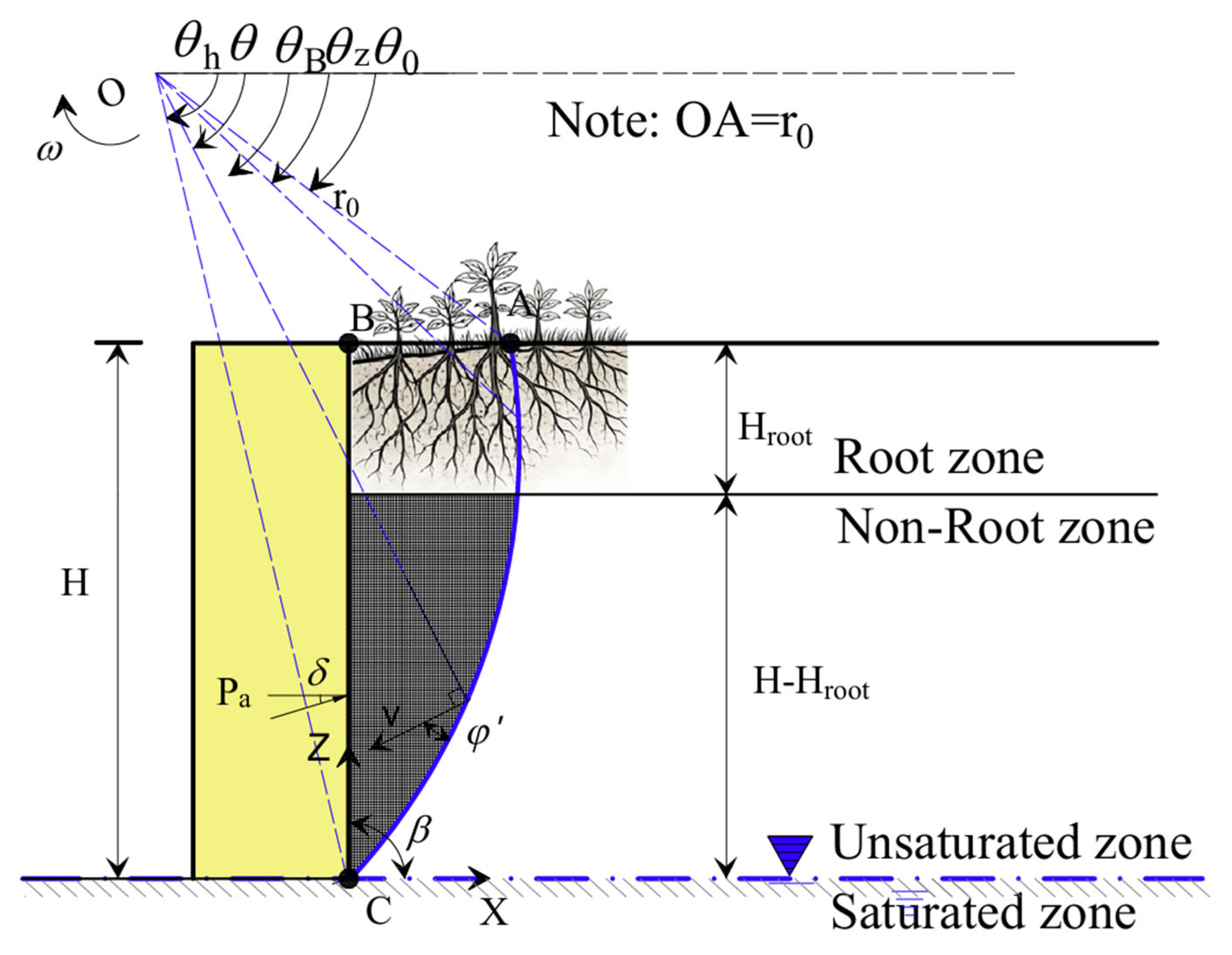
Based on the above considerations, a suitable failure mechanism is required for the upper-bound analysis. For frictional backfills under active earth pressure conditions, both experimental observations and previous theoretical studies indicate that the failure surface is more likely to be curved than strictly planar. For this reason, a planar wedge mechanism is not adopted here, as it may not adequately represent the rotational nature of failure in frictional soils. In upper-bound limit analysis, the logarithmic spiral is a commonly used kinematically admissible mechanism for frictional geomaterials. It can reasonably describe the curved failure pattern while still allowing the work and dissipation terms to be derived in a manageable analytical form. Therefore, it is adopted in the present study as a practical mechanism that captures the main mechanical features of the problem without making the formulation unnecessarily complicated. Since this study aims to establish a two-dimensional plane-strain framework for evaluating the active earth pressure coefficient of vegetated retaining walls, the potential failure surface is assumed to follow a two-dimensional logarithmic spiral, as illustrated in Figure 1. A global coordinate system X–Z is introduced, with the X-axis positive to the right and the Z-axis positive upward, and the origin located at the base of the wall. The failure surface is then expressed in polar coordinates as
r = r 0 e θ θ 0 tan φ
where r0 denotes the initial radius of the failure surface, while θ0 and θh represent the polar angles at the wall toe and the ground surface, respectively.

3.2. Power Balance Equation and Energy Dissipation Analysis

Under the selected logarithmic-spiral mechanism, the active failure of the retaining wall is modeled as a rigid-body rotation of the backfill around a center of rotation. According to the upper-bound theorem, the total rate of external work must equal the total rate of internal energy dissipation at the limit state. The general power balance equation is expressed as
W γ = D c + D c app root + D p root + W p a
Here, Dc represents the cohesion-related dissipation of the soil skeleton only. The suction-related contribution is introduced separately through σ s and its associated frictional work along the failure surface. Therefore, suction is not counted again in Dc.
For retaining structures under unsaturated conditions, three-dimensional formulations of active earth pressure have been advanced to account for transient unsaturated flow, tensile strength cut-off in cohesive backfills, and tension-crack effects under steady unsaturated seepage, providing complementary perspectives for benchmarking and scope positioning of the present 2D plane-strain LA framework [22,39,40].
where Wγ is the rate of work done by the soil self-weight, Dc is the rate of internal energy dissipation due to soil cohesion along the failure surface, D p root is the rate of energy dissipation induced by root pull-out resistance, D c app root is the rate of energy dissipation resulting from transpiration-induced suction stress, and W p a  is the rate of work done by the retaining-wall supporting force.
It is important to note that the presence of vegetation does not alter the geometric configuration of the failure surface. Instead, it enhances the overall stability of the system by contributing additional internal work terms. This mechanism is fundamentally different from traditional approaches that simplify vegetation effects into an equivalent additional cohesion.

3.3. Work of Soil Self-Weight and Cohesive Energy Dissipation

Under the assumed velocity field, the rate of work done by the soil self-weight is calculated by volume integration over the rotating logarithmic-spiral failure region. By collecting the resulting geometric terms into compact dimensionless coefficient functions, the final expression can be written as
W γ = γ r 0 3 ω f 1 f 2 f 3
where f1f3 are dimensionless functions dependent on the geometry of the failure surface and the internal friction angle, expressed as
f 1 = 3 tan φ cos θ h + sin θ h e 3 θ h θ 0 tan φ 3 tan φ cos θ 0 + cos θ 0 3 1 + 9 tan 2 φ
f 2 = L 6 r 0 2 cos θ 0 L r 0 sin θ 0
f 3 = 1 6 e θ h - θ 0 tan φ sin θ h - θ 0 L r 0 sin θ h cos θ 0 L r 0 + cos θ h e θ h - θ 0 tan φ
The rate of energy dissipation due to cohesion is obtained by integrating the Mohr–Coulomb cohesive resistance along the logarithmic-spiral failure surface under the adopted velocity discontinuity, and can be written as
D c = ω c r 0 3 f 4
where c′ denotes the cohesion of the backfill, and f4 is a dimensionless function dependent on the failure surface, expressed as
f 4 = 1 2 tan φ e 2 θ h θ 0 tan φ 1

3.4. Formulation of Energy Dissipation Due to Root Pull-Out

When vegetation roots are present within the potential failure zone, they undergo gradual stretching during soil displacement, thereby mobilizing resistance at the root–soil interface. For woody vegetation, root reinforcement may involve tensile mobilization of structural roots and interface pull-out of fine-to-medium roots. In the present LA formulation, the root contribution along the potential failure surface is represented through an equivalent pull-out work term, which provides a tractable and conservative description of interface-controlled resistance [41,42].
On a macroscopic scale, the collective action of a root system can be idealized as an equivalent additional resistance distributed along the kinematically admissible failure path. However, explicitly resolving the spatial distribution of numerous roots is computationally prohibitive in an upper-bound framework. Therefore, the pull-out resistance mobilized within an effective rooting height is represented by an equivalent control point. In this way, the distributed pull-out contribution of roots within the rooted zone is replaced by an equivalent analytical representation, from which the compact work expression is obtained.
The effective rooting height is denoted as Hroot, and its normalized form is introduced as
η = H root H
where η 0.0 , 1.0 is a calibration coefficient. Within the root zone, the root area ratio (RAR) is assumed uniform:
R A R z = R A R 0 , z H , H H root 0 , z 0 , H H root
Let Nroot be the number of roots per unit area root / m 2 and di the representative root diameter. By definition, the area fraction satisfies
R A R 0 = N root π d i 2 4 , N root = 4 R A R 0 π d i 2
In the plane-strain setting (unit out-of-plane width), the number of roots contained in a vertical strip of thickness dz is Nrootdz.
The equivalent control depth z ˜ is defined as
z ˜ = H κ H r o o t
where κ 0 , 1 is a calibration coefficient. This simplified approach using an equivalent control point is adopted to avoid the complex integration of numerous discrete roots along the failure surface, which is computationally prohibitive in upper-bound analysis. The parameter κ conceptually represents the relative depth within the root zone where the integrated pull-out resistance is effectively mobilized. κ can be conservatively taken as 0.5, implying a uniform distribution of root resistance over the rooting depth, or calibrated against detailed numerical simulations or experimental pull-out test data if available. The equivalent control point is taken as the intersection between the failure surface z(θ) and the horizontal line z = z ˜ . The corresponding polar angle is denoted as θz. Consequently, the rate of energy dissipation can be expressed as
D p root = ω r 0 i = 1 N root F i sin θ z ϑ e θ z θ 0 tan φ = ω γ r 0 3 f 6
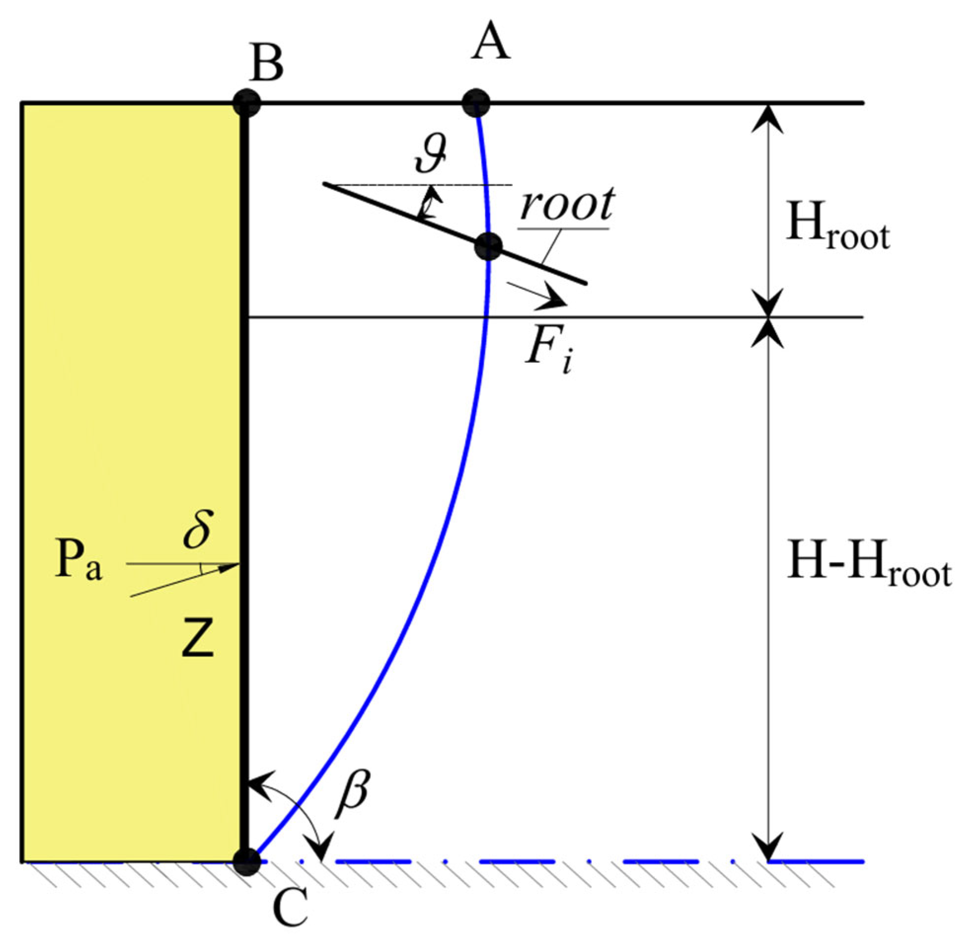
where Nroot represents the number of roots per unit area, which is considered equivalent to the root quantity per unit depth in this study; Fi denotes the shear resistance of a single root, as detailed in Section 2; and ϑ represents the angle formed by the root and the horizontal plane, as shown in Figure 2. The figure illustrates the reference case adopted in this study, namely a vertical retaining wall with β = 90°, unless otherwise stated. Additionally, f6 is a dimensionless function that comprehensively incorporates the effects of root density, diameter, anchorage length, spatial distribution, and orientation, which can be expressed as
f 6 = N root sin β H r 0 π d i ξ 1 l i r 0 μ ξ 2 l max sin ϑ sin θ z ϑ e θ z θ 0 tan φ
where ξ1 is the correction coefficient for the root anchorage depth, and ξ2 is the correction coefficient for the maximum root growth length.
This approach avoids the direct modification of soil strength parameters, thereby maintaining consistency with the energy-based principles of upper-bound analysis [43].

3.5. Formulation of Energy Dissipation Due to Transpiration-Induced Suction Stress

In addition to mechanical reinforcement, vegetation significantly alters the hydraulic state of the backfill through root water uptake and transpiration. Under unsaturated conditions, transpiration can generate sustained matric suction within the root zone, thereby modifying the effective stress distribution and stability [44]. Based on the hydraulic model established in the previous section, the suction stress induced by transpiration acts as an additional compressive normal stress along the failure surface. Within the adopted Mohr–Coulomb framework, this normal-stress increment generates an additional frictional resistance, whose internal work rate is evaluated in the upper-bound formulation as follows:
D c app root = ω r 0 2 f 5
where f5 denotes the contribution coefficient for internal energy dissipation induced by root transpiration under the logarithmic-spiral failure model, expressed as
f 5 = tan φ θ 0 θ h σ s z e 2 θ θ 0 tan φ d θ
where σs has been derived in the previous chapter. The parameters involving z are transformed into polar coordinates to express all variables in terms of the polar angle:
z θ = H + r 0 sin θ 0 r sin θ
This integral form clearly captures the spatially cumulative effects of transpiration. Moreover, it naturally differentiates the varying contributions of the rooted and non-rooted zones to stability.

3.6. Expressions for Active Earth Pressure and Its Coefficient

When the retained soil reaches a state of incipient failure, the retaining wall provides a resultant supporting force, Pa, which performs external work in the virtual-work formulation. This force is the reaction to the active earth pressure and is therefore equal in magnitude and opposite in direction to the resultant active thrust.
In the present two-dimensional framework, the point of application of the resultant force is assumed to be located at H/3 above the wall base. This is introduced as a conventional simplifying assumption for evaluating the external work term, rather than as a rigorous prediction of the actual stress distribution in vegetated unsaturated backfills. In other words, the present formulation does not require the active earth pressure to be strictly linear with depth; the H/3 assumption is adopted to provide a tractable closure for the virtual-work analysis. In addition, the retaining wall is idealized as a planar rigid boundary. Accordingly, the possible effects of non-planar wall geometry, wall batter variation, or wall deformation mode on the exact location of the resultant force are not explicitly considered in the present model. This simplification mainly affects the precise prediction of the resultant application point, but it does not alter the comparative parameter trends and relative changes in Ka that are the main focus of this study. Furthermore, the angle between the resultant supporting force and the normal to the wall surface is taken as the wall–soil interface friction angle, δ. Under the adopted rigid-body rotation mechanism, the rate of work done by the supporting force is evaluated by using the conventional H/3 application-point assumption together with the wall–soil interface friction angle δ, and can be written as
W p a = ω r 0 P a f 7
where f7 is given by
f 7 = sin β + δ sin θ h e θ h θ 0 tan φ 1 3 H r 0 cos β + δ cos θ h e θ h θ 0 tan φ 1 3 H r 0 cot β
where δ denotes the wall–soil interface friction angle.
By combining the expressions for the various power terms derived above, the active earth pressure on the retaining wall is obtained as
P a = W γ D c D c app root D p root W p a / P a
To facilitate the representation of the calculated results, a dimensionless coefficient is introduced. This parameter is termed the active earth pressure coefficient and is defined as
K a = 2 P a γ H 2
This formulation establishes the evaluation framework proposed in this study for active earth pressure on retaining walls, incorporating the combined effects of root pull-out resistance and transpiration.
Therefore, the proposed mechanism can be characterized by the unknown parameters θ0 and θh, together with the prescribed quantities such as H, Hroot, and β. Accordingly, the most critical condition—corresponding to the maximum value of Ka—can be identified by an optimization procedure. To ensure the physical admissibility of the assumed failure mechanism, the following conditions should be satisfied:
θ 0 θ θ h < π / 2 θ 0 < θ z < θ h < π / 2 0 H root / H 1
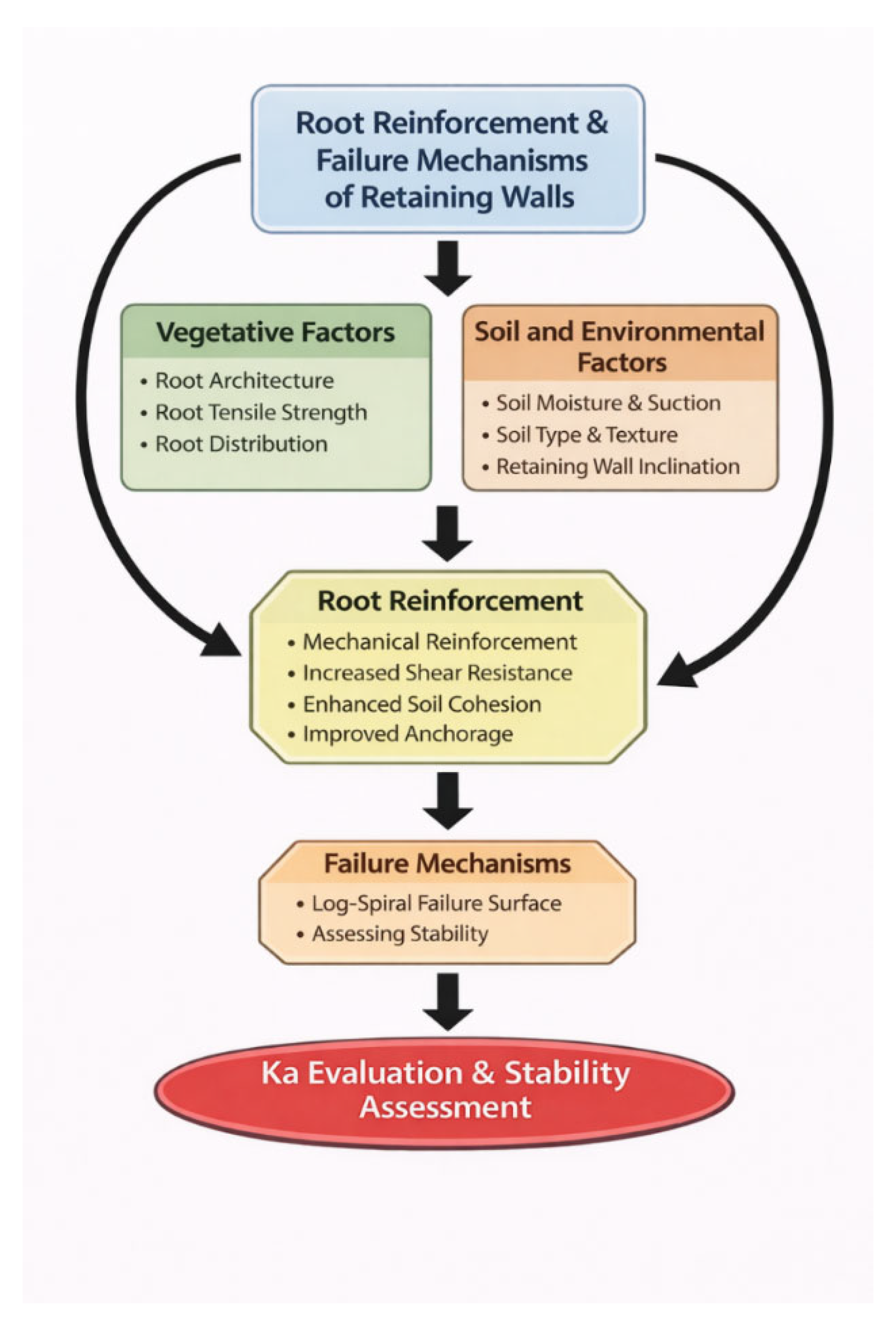
This study investigates the mechanisms by which plant roots improve the stability of retaining walls. The analysis is conducted based on a log-spiral failure surface, as illustrated in Figure 3, and includes the evaluation of the active earth pressure coefficient.

4. Parametric Design Charts and Discussion for Vegetated Retaining Walls

Following the energetic formulation developed in Section 2 and Section 3, vegetation influences are introduced as additional internal work terms—root pull-out dissipation and transpiration-induced suction stress—without changing the kinematic failure mechanism. To facilitate interpretation, the results are organized into six chart families: (i) and (ii) Ka–tanφ′ maps under combined vegetation actions; (iii) KaT curves highlighting suction sensitivity; (iv) Kaη curves to quantify the effectiveness of rooting depth/coverage; (v) constant-RAR charts varying representative root diameter d; and (vi) constant-d charts varying root area ratio (RAR). Throughout this chapter, η = Hroot/H is used as the normalized rooting height, and “root-zone coverage” refers to the fraction of the wall height intersected by the rooted zone in the adopted kinematic mechanism. Unless otherwise noted, all curves correspond to the upper-bound solution obtained by a consistent two-parameter search over the failure mechanisms θ0 and θh. Maintaining identical search resolution across parametric sweeps ensures that observed differences in Ka reflect physical parameter effects rather than numerical artifacts.

4.1. Study Framework, Parameter Ranges and Benchmark Checks

The numerical results are primarily intended for trend comparison and the development of design-oriented charts, rather than site-specific prediction. Because both root pull-out and transpiration-induced suction are highly dependent on plant species, root architecture, and soil hydraulic properties, rigorous external validation would require independent datasets and calibration; this is beyond the scope of the present study. Therefore, the implementation-level verification adopts a degeneracy (benchmark) check: when vegetation-related internal work terms are suppressed, the formulation must reduce to the conventional non-vegetated 2D LA and remain consistent with classical solutions. Parameter ranges are selected to be representative of typical backfill conditions and to allow clear contrast between a high-permeability granular soil (sand) and a low-permeability fine-grained soil (clay). For the hydraulic component, the Gardner-type unsaturated conductivity and the soil water retention behavior govern the attainable suction distribution under steady vertical flow. Consequently, the same transpiration rate T may generate markedly different suction stresses in the two soils, which is intentionally exploited here to highlight the role of permeability and retention parameters. In addition to the “vegetation-off” degeneracy test, two practical consistency checks are applied during post-processing: (i) the computed Ka must decrease with increasing tanφ′ and (ii) Ka must be non-increasing when stabilizing vegetation parameters (η, RAR, or T in suction-dominant soils) are increased, for a fixed mechanical setting. Any violation would indicate either insufficient search resolution or an implementation error. Two representative soil types (sand and clay) are considered. The comparative parameter set is listed in Table 1, where c / γ H represents the reciprocal of the normalized critical height, with data originating from Vahedifard et al. [38] and Lu and Godt [45]. Unless otherwise specified, the parameter values listed in Table 1 are adopted throughout this study.
Root-zone coverage ratios are taken as 25%, 50%, 75% and 100%. The transpiration rate is varied as T = 0, 1, 3 and 5 mm/day.
Table 2 compares the computed active earth pressure coefficient Ka; the present results are in excellent agreement with those of Yang and Li [46] across all cases. Based on previous work [47,48,49], some new discussions are presented. For most practical ranges (e.g., δ/φ′ ≤ 1/2), the discrepancies remain within 1%, which is comparable to rounding-level differences. This comparison indicates that, when the vegetation-related work terms are suppressed, the present formulation correctly degenerates to the corresponding non-vegetated upper-bound solution, and the numerical optimization has been implemented consistently. Such agreement should be interpreted as a validation of formulation consistency and implementation, rather than as an independent proof of the uniqueness or correctness of the adopted logarithmic-spiral mechanism itself. On this basis, the subsequent sections focus on the vegetation contributions, where root pull-out resistance and transpiration-induced suction stress are reintroduced to quantify their individual and combined influences on Ka and the resultant active earth pressure. Unless otherwise stated, the parametric results presented in this study are generated for a vertical retaining wall (β = 90°). Accordingly, Figure 2 illustrates this reference configuration.

4.2. Frictional Strength Effects and Coupled Vegetation Actions

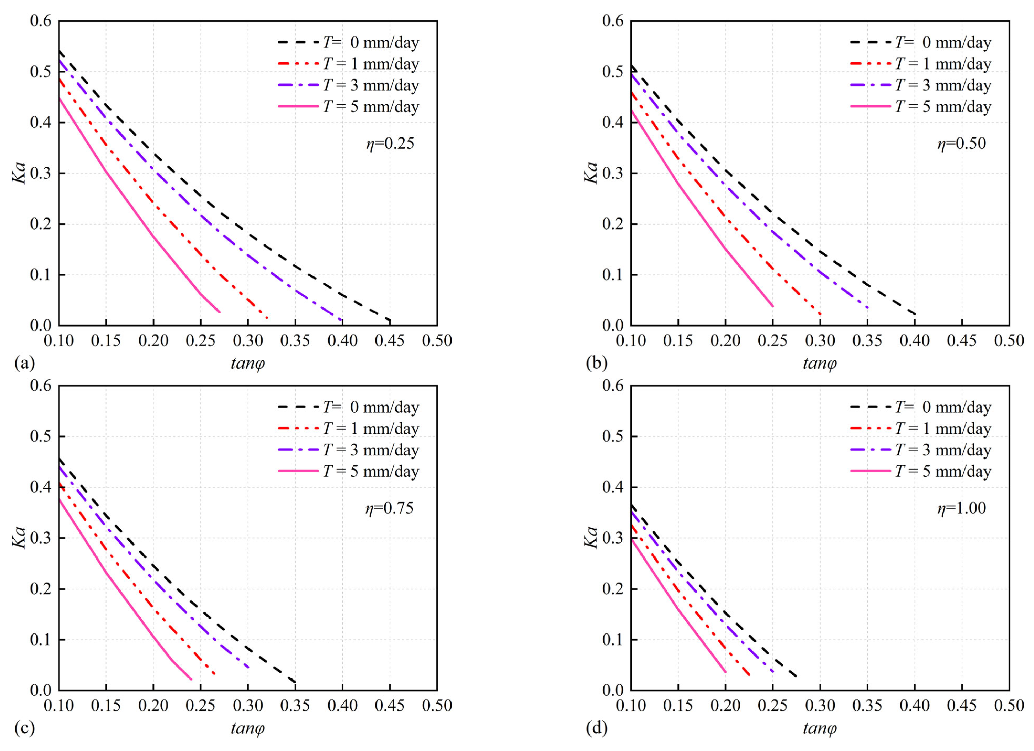
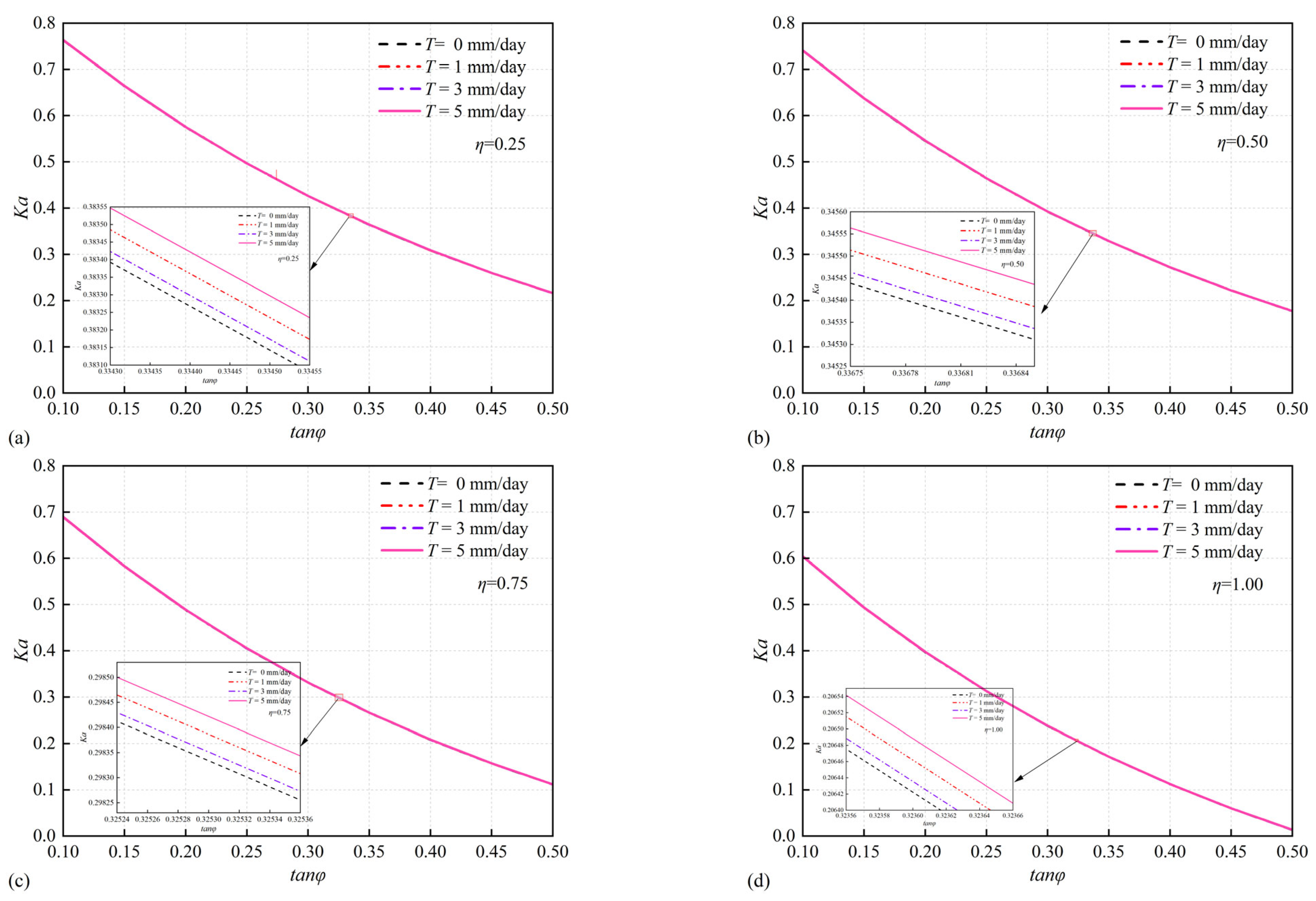
Figure 4 and Figure 5 show Ka plotted against tanφ′ for different root-zone coverage ratios and transpiration rates. For both soil types, Ka decreases monotonically with increasing tanφ′, consistent with classical earth pressure behavior. Vegetation further reduces Ka through additional internal dissipation, but the magnitude and sensitivity of the reduction depend strongly on soil hydraulic properties. A notable feature of the Ka–tanφ′ maps is that vegetation-induced reductions are generally more pronounced when the root-zone coverage ratio increases, implying that the effectiveness of suction stress is controlled by the depth/extent of the rooted zone. For the selected sand parameters, the Ka–tanφ′ curves for different T nearly coincide: Table 3 shows that the contribution of the maximum transpiration rate to the change in Ka, relative to the no-transpiration condition, is almost always less than 0.2%, which is practically negligible. It suggests that transpiration-induced suction contributes marginally under the selected high-permeability conditions. The vegetation effect is dominated by mechanical root pull-out dissipation, and T primarily acts as a secondary factor. Therefore, the influence of transpiration rate on sand is not discussed further in the following analysis.

4.3. Sensitivity to Transpiration Rate: K a –T Curves at Multiple Rooting Heights

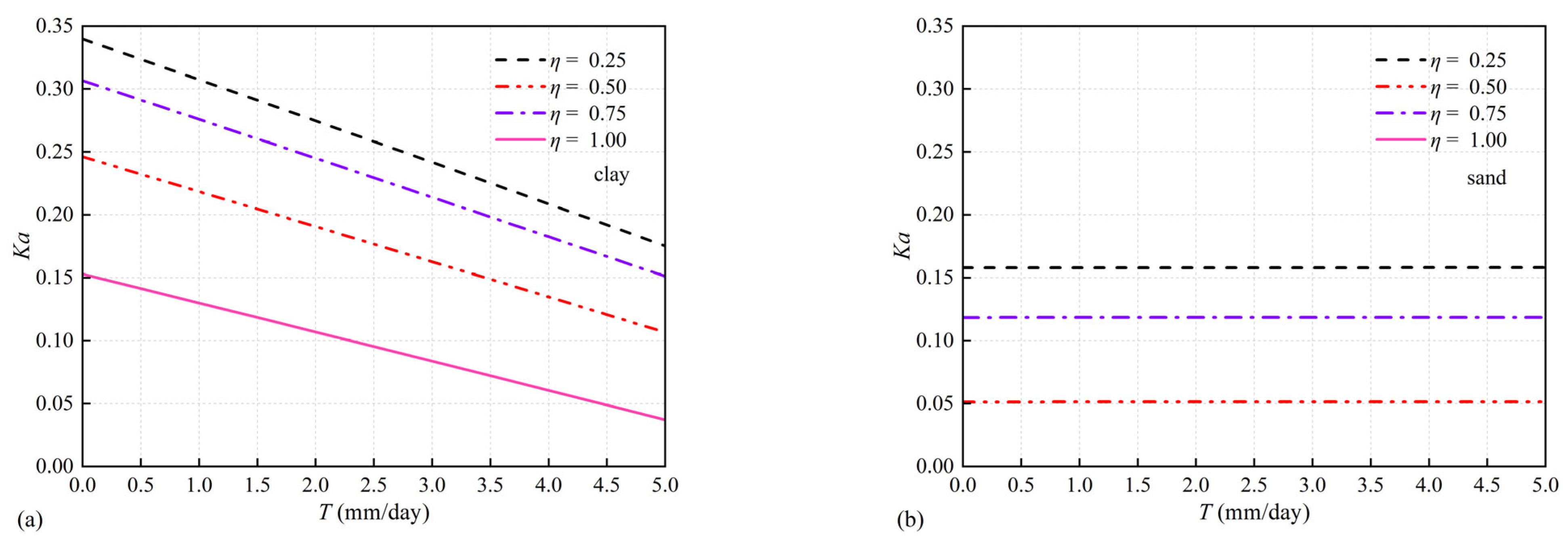
To isolate the influence of transpiration, Figure 6 presents Ka as a function of T for four normalized rooting heights η = Hroot/H. For clarity of presentation, φ values are set as follows: 11.2° for clay (corresponding to tanφ′ = 0.2 in Figure 4) and 30° for sand. Unless otherwise specified, these values are adopted throughout the remaining sections. For clay, Ka decreases systematically with T for all η. Larger η yields lower Ka and also a steeper response to T, demonstrating a coupling between rooting extent and suction stress dissipation. For clay, the approximately monotonic decrease in Ka with T suggests that the modeled suction field strengthens with increasing transpiration demand under steady-state conditions. However, the response is not expected to be unbounded in reality: suction development is constrained by air entry behavior and the reduction in hydraulic conductivity with suction. This provides a physical basis for potential “saturation” of the KaT trend at higher T. For sand, the weak dependence on T indicates that either the suction distribution remains close to zero within the rooted zone due to rapid drainage or suction is localized and contributes little integrated work along the failure mechanism. In practice, this implies that transpiration-driven suction should not be relied upon as a primary stabilizing mechanism for highly permeable backfills unless additional factors (e.g., capillary barriers, fines content, or controlled irrigation/drying cycles) are present. For sand, Ka is almost insensitive to T across the investigated range, while the absolute level of Ka still decreases with η. This behavior is consistent with the limited suction build-up expected in high-permeability backfills and indicates that design benefits in sand are mainly achieved by increasing mechanical root contribution (e.g., rooting depth and RAR), rather than relying on T.

4.4. Rooting-Height Effectiveness and Diminishing Returns Under Varying Transpiration

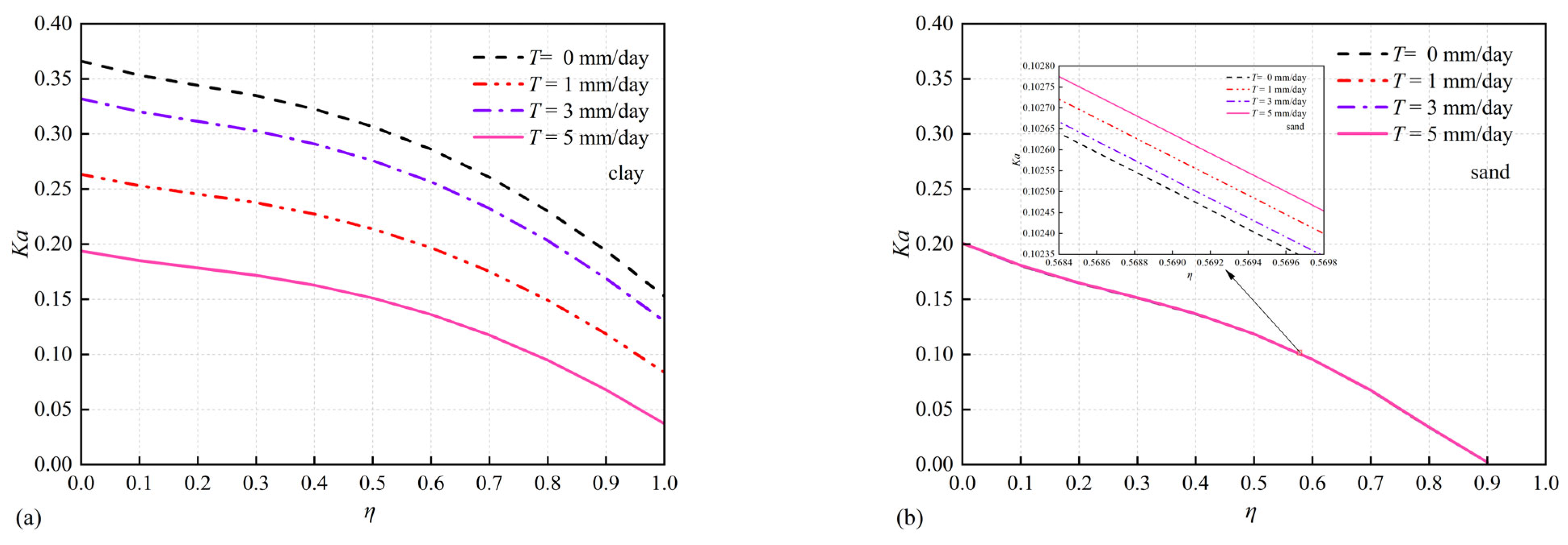
Figure 7 further examines the impact of normalized rooting height η under different T. For clay, Ka decreases with η for all T, and the reduction is amplified when T increases. The curves are generally nonlinear, indicating diminishing marginal benefit at either very small or very large η, depending on the considered T level. This highlights the importance of selecting an effective rooting height rather than simply maximizing η. The nonlinear form of the Kaη curves can be interpreted through geometric mobilization. At small η, only a limited portion of the admissible failure surface intersects the rooted zone, so both pull-out dissipation and suction stress work are weakly mobilized. As η increases, a larger fraction of the failure path is embedded in the rooted zone and the vegetation contribution grows rapidly. Beyond a certain η, however, additional rooting depth contributes progressively less because the critical failure mechanism concentrates near the wall and the incremental rooted region overlaps less with the most active deformation zone, producing diminishing returns. For design interpretation, it is useful to identify an “effective rooting height” ηeff, which provides a rational basis for choosing planting strategies or engineered root zones that balance performance with constructability and maintenance. For sand, the ηKa curves for different T almost overlap, reaffirming that T has negligible influence under the chosen sand hydraulic parameters. Nevertheless, η remains an effective mechanical lever: increasing η extends the root–failure intersection region and increases the mobilized pull-out dissipation, thereby reducing Ka.

4.5. Root Architecture Controls: RAR–Diameter Trade-Off and Equivalent Configurations

Beyond rooting height, the root architecture parameters (root area ratio RAR and representative root diameter d) are investigated through two complementary sets of charts. The two chart families (constant RAR and constant d) are designed to expose the competing roles of root size and root number density. Under a fixed RAR, increasing d reduces the number of roots per unit area, while each individual root may exhibit higher pull-out resistance. The net effect depends on the adopted pull-out model and the considered range of d. For the present formulation and parameter range, the density effect dominates, leading to an overall increase in Ka with increasing d at constant RAR. Conversely, at fixed d, increasing RAR primarily increases root number density and therefore the integrated pull-out work along the failure path. This provides a direct “design dial” for mechanical reinforcement in both soils, and it can be readily linked to field-observable root metrics or engineered inclusions that mimic root pull-out behavior.

4.5.1. Constant RAR, Varying d

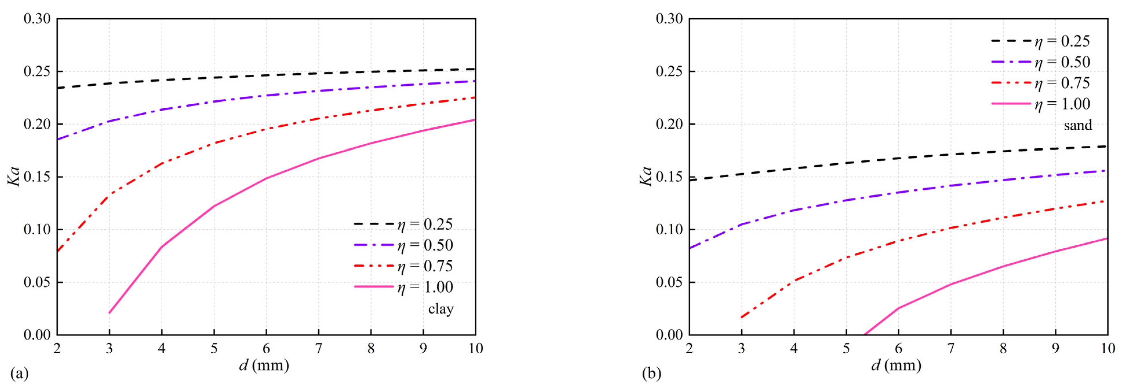
As shown in Figure 8, when RAR is fixed, increasing d reduces the number of roots per unit area (NrootRAR/d2). Consequently, the collective pull-out dissipation decreases and Ka tends to increase with d. This trend appears in both clay and sand, and becomes more evident at larger η where the root contribution is more fully mobilized.

4.5.2. Constant d, Varying RAR

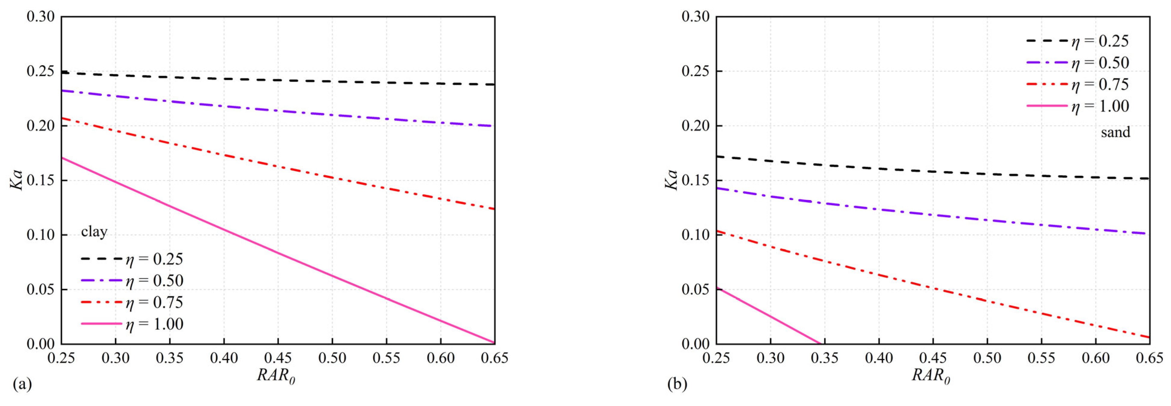
As shown in Figure 9, for a fixed d, increasing RAR increases Nroot and thus the integrated pull-out dissipation, leading to a monotonic decrease in Ka. The benefit is stronger for larger η because more of the failure surface passes through the rooted zone. These two charts together provide a practical design message: for a target RAR level, a finer-root system (smaller d with higher root number density) is generally more effective than a coarse-root system in reducing Ka, provided that pull-out (rather than tensile rupture) governs root mobilization.

4.6. Engineering Stability Insights, Limitations, and Recommended Use of the Charts

Based on the presented charts, several main stability insights can be identified. Increasing tanφ′ consistently reduces Ka, and vegetation provides additional reductions at the same tanφ′. Transpiration-induced suction is highly effective in low-permeability soils (clay) but may be negligible in high-permeability soils (sand) within the investigated parameter range. The rooting height η is an effective stabilizing variable in both soils; in clay, it also governs how strongly Ka responds to transpiration demand T. For a fixed RAR, larger root diameter increases Ka because of the reduction in root number density, whereas for a fixed diameter, increasing RAR decreases Ka. These results suggest that clay backfills can benefit from both hydraulic regulation and mechanical reinforcement, while sand backfills should rely mainly on mechanical root attributes such as η and RAR for reliable reductions in active earth pressure.
These findings should be interpreted together with the assumptions of the present model. The transpiration-driven suction contribution is evaluated under a steady-state vertical-flow idealization and a prescribed transpiration demand, and therefore represents an idealized estimate of hydraulic stabilization. In the field, seasonal variability, preferential flow, root distribution heterogeneity, and temperature-dependent hydraulic properties may alter the magnitude of suction and its persistence. In addition, the root system is represented using simplified architectural parameters, and the adopted failure mechanism is two-dimensional.
Accordingly, the charts are best used for comparative design screening and for identifying controlling parameters, rather than for direct prediction without site calibration. A practical use sequence is as follows: first select the soil type, or bracket the response between sand-like and clay-like behavior; then read Ka from the relevant chart family for the chosen tanφ′, η, T, RAR, and d; next evaluate the reduction relative to the vegetation-free baseline; and finally identify parameter ranges with diminishing returns to support practical design decisions.

5. Conclusions

This study proposes a unified upper-bound limit analysis framework for evaluating the active earth pressure of vegetated retaining walls under unsaturated conditions. Root reinforcement and transpiration-induced suction are incorporated as two distinct vegetation-related contributions within an energy-based formulation. To verify the consistency of the formulation and its numerical implementation, the vegetation-related work terms were suppressed so that the model degenerates to the corresponding non-vegetated limit-analysis case. The resulting Ka values show good agreement with the benchmark solution across the investigated cases, indicating that the degenerated formulation is consistent and that the optimization procedure has been implemented correctly. This agreement should be understood as a benchmark consistency check, rather than as an independent proof of the uniqueness of the adopted logarithmic-spiral mechanism. Based on the generated parametric charts, the main findings are summarized as follows:
  • The parametric results show that, for both soil types, Ka decreases monotonically with increasing tanφ′, which is consistent with the classical trend of active earth pressure. Vegetation provides an additional reduction in Ka by introducing extra internal dissipation, although the extent of this benefit depends strongly on the hydraulic characteristics of the backfill.
  • The influence of transpiration is markedly soil-dependent. In low-permeability clay, Ka decreases systematically as the transpiration rate T increases, indicating that transpiration-induced suction can be effectively mobilized under the adopted steady-state hydraulic condition. By contrast, in high-permeability sand, the variation in Ka with T is negligible within the investigated range, suggesting that transpiration-driven suction does not play a dominant stabilizing role in such backfills.
  • The rooting height also has a clear effect on wall stability. Increasing the normalized rooting height, η = Hroot/H, consistently reduces Ka. However, this reduction is generally nonlinear, and the marginal benefit gradually diminishes as η becomes larger. This is because the critical deformation zone is concentrated near the wall, so extending the rooted depth further downward contributes progressively less to the most mobilized part of the failure mechanism.
  • Root architecture shows a clear trade-off between root size and root density. At a constant RAR, increasing the root diameter d tends to increase Ka, because the corresponding decrease in root number density reduces the total pull-out dissipation. In contrast, when d is fixed, increasing RAR enhances root density and the integrated pull-out work along the failure surface, leading to a monotonic decrease in Ka.
It should be noted that the present analysis is based on a steady-state hydrological assumption and simplified root architecture representation, which may limit its direct application to scenarios with strong transient effects or highly heterogeneous root systems. Future work should focus on extending the framework to transient flow conditions, validating the model against field monitoring data, and exploring three-dimensional failure mechanisms for a more comprehensive understanding of vegetated-retaining-wall performance. The proposed chart families are intended for comparative design screening and for identifying controlling parameters, rather than direct site-specific prediction. The hydraulic contribution is evaluated under a steady-state vertical-flow idealization with prescribed transpiration demand; field factors such as seasonal variability, preferential flow, and heterogeneous root distributions may alter suction magnitude and persistence. Future work may extend the framework to transient seepage and higher-dimensional mechanisms, supported by calibration against site-relevant suction and root–soil interaction data.

Author Contributions

Conceptualization, G.L.; Methodology, L.X.; Software, L.R.; Validation, R.W.; Formal analysis, G.L.; Resources, L.X.; Data curation, L.R.; Writing–original draft, R.W.; Writing–review & editing, C.W.; Supervision, C.W. All authors have read and agreed to the published version of the manuscript.

Funding

This work was supported by the project “Key technologies for deformation control in shield tunneling through operated subway station and utility tunnels” of Shenzhen Municipal Group Co., Ltd., and the project “Key technologies for TBM safe tunneling under unfavorable geological conditions” of Shenzhen Municipal Group Co., Ltd.

Data Availability Statement

The data presented in this study are available on request from the corresponding author. The data are not publicly available as they are the proprietary research data of our team and will be used for subsequent in-depth research on the subject.

Conflicts of Interest

Authors Long Xia, Guihua Long, and Liwei Ren were employed by the Shenzhen Municipal Group Co., Ltd. The remaining authors declare that the research was conducted in the absence of any commercial or financial relationships that could be construed as potential conflicts of interest.

References

  1. Cheng, Z.; Zhou, D.; Chen, Q.; Gu, S. Safety Analysis of Subway Station under Seepage Force Using Continuous Velocity Field. Mathematics 2025, 13, 2541. [Google Scholar] [CrossRef] [Scilit]
  2. Xie, Y.; Zhou, D.; Liao, H.; Zhu, J. Failure Mode of Tunnel Face under Transient Unsaturated Seepage with Temperature Influence. Mathematics 2025, 13, 1311. [Google Scholar] [CrossRef] [Scilit]
  3. Greenwood, J.R.; Norris, J.E.; Wint, J. Assessing the contribution of vegetation to slope stability. Geotech. Eng. 2004, 157, 199–207. [Google Scholar] [CrossRef]
  4. Lann, T.; Bao, H.; Lan, H.; Zheng, H.; Yan, C.; Peng, J. Hydro-mechanical effects of vegetation on slope stability: A review. Sci. Total Environ. 2024, 926, 171691. [Google Scholar] [CrossRef] [Scilit]
  5. Shan, J.T.; Yang, X.L.; Xia, L.; Long, G.H.; Yang, B.Y.; Ren, L.W. Influence of plant root reinforcement on 3D geosynthetic slopes. J. Cent. South Univ. 2026. [Google Scholar] [CrossRef] [Scilit]
  6. Lobmann, M.T.; Geitner, C.; Wellstein, C.; Zerbe, S. The influence of herbaceous vegetation on slope stability—A review. Earth-Sci. Rev. 2020, 209, 103328. [Google Scholar] [CrossRef] [Scilit]
  7. Wu, T.H. Root reinforcement of soil: Review of analytical models, test results, and applications. Can. Geotech. J. 2013, 50, 259–274. [Google Scholar] [CrossRef] [Scilit]
  8. Waldron, L.J. The shear resistance of root-permeated homogeneous and stratified soil. Soil Sci. Soc. Am. J. 1977, 41, 843–849. [Google Scholar] [CrossRef] [Scilit]
  9. Wu, T.H.; McKinnell, W.P.; Swanston, D.N. Study of soil-root interaction. J. Geotech. Eng. 1988, 114, 1351–1375. [Google Scholar] [CrossRef] [Scilit]
  10. Smethurst, J.A.; Clarke, D.; Powrie, W. Observed and modelled seasonal changes in pore water pressure in a grass-covered cut slope. Géotechnique 2006, 56, 523–537. [Google Scholar] [CrossRef] [Scilit]
  11. Leung, A.K.; Ng, C.W.W. Analyses of groundwater flow and plant evapotranspiration in a vegetated soil slope. Can. Geotech. J. 2013, 50, 1204–1218. [Google Scholar] [CrossRef] [Scilit]
  12. Feng, S.; Liu, H.W.; Ng, C.W.W. Analytical analysis of the mechanical and hydrological effects of vegetation on shallow slope stability. Comput. Geotech. 2020, 119, 103335. [Google Scholar] [CrossRef] [Scilit]
  13. Switala, B.M.; Wu, W. Modelling the hydrological effects of vegetation on slope stability. Géotechnique 2018, 68, 592–604. [Google Scholar]
  14. Ng, C.W.W.; Zhang, Q.; Ni, J.; Li, Z. A new three-dimensional theoretical model for analysing the stability of vegetated slopes with different root architectures and planting patterns. Comput. Geotech. 2021, 132, 104020. [Google Scholar] [CrossRef] [Scilit]
  15. Liu, H.W.; Feng, S.; Ng, C.W.W. Analytical analysis of hydraulic effect of vegetation on shallow slope stability with different root architectures. Comput. Geotech. 2016, 80, 115–120. [Google Scholar] [CrossRef] [Scilit]
  16. Yang, X.L.; Yin, J.H. Slope stability analysis with nonlinear failure criterion. J. Eng. Mech. 2004, 130, 267–273. [Google Scholar] [CrossRef] [Scilit]
  17. Yang, X.L.; Huang, F. Collapse mechanism of shallow tunnel based on nonlinear Hoek-Brown failure criterion. Tunn. Undergr. Space Technol. 2011, 26, 686–691. [Google Scholar] [CrossRef] [Scilit]
  18. Yang, X.L.; Wang, J.M. Ground movement prediction for tunnels using simplified procedure. Tunn. Undergr. Space Technol. 2011, 26, 462–471. [Google Scholar] [CrossRef] [Scilit]
  19. Lu, N.; Godt, J.W.; Wu, D.T. A closed-form equation for effective stress in unsaturated soil. Water Resour. Res. 2010, 46, W05515. [Google Scholar] [CrossRef] [Scilit]
  20. Lu, N.; Likos, W.J. Suction stress characteristic curve for unsaturated soil. J. Geotech. Geoenvironmental Eng. 2006, 132, 131–142. [Google Scholar] [CrossRef] [Scilit]
  21. Cheng, P.; Wu, L.; Zhang, H.; Zhou, J. Inclusion of root water absorption and reinforcement in upper bound limit stability analysis of vegetated slopes. Comput. Geotech. 2024, 170, 106175. [Google Scholar] [CrossRef] [Scilit]
  22. Li, Z.W.; Yang, X.L. Three-dimensional active earth pressure under transient unsaturated flow conditions. Comput. Geotech. 2020, 123, 103559. [Google Scholar] [CrossRef] [Scilit]
  23. Van Genuchten, M.T. A closed-form equation for predicting the hydraulic conductivity of unsaturated soils. Soil Sci. Soc. Am. J. 1980, 44, 892–898. [Google Scholar] [CrossRef] [Scilit]
  24. Gardner, W.R. Some steady-state solutions of the unsaturated moisture flow equation with application to evaporation from a water table. Soil Sci. 1958, 85, 228–232. [Google Scholar] [CrossRef] [Scilit]
  25. Fredlund, D.G.; Rahardjo, H. Soil Mechanics for Unsaturated Soils; Wiley: New York, NY, USA, 1993. [Google Scholar]
  26. Bischetti, G.B.; Chiaradia, E.A.; Simonato, T.; Speziali, B.; Vitali, B.; Vullo, P.; Zocco, A. Root strength and root area ratio of forest species in Lombardy (Northern Italy). Plant Soil 2005, 278, 11–22. [Google Scholar] [CrossRef] [Scilit]
  27. De Baets, S.; Poesen, J.; Reubens, B.; Wemans, K.; De Baerdemaeker, J.; Muys, B. Root tensile strength and root distribution of typical Mediterranean plant species and their contribution to soil shear strength. Plant Soil 2008, 305, 207–226. [Google Scholar] [CrossRef] [Scilit]
  28. Fan, C.C.; Su, C.F. Role of roots in the shear strength of root-reinforced soils with high moisture content. Ecol. Eng. 2008, 33, 157–166. [Google Scholar] [CrossRef] [Scilit]
  29. Mickovski, S.B.; Hallett, P.D.; Bransby, M.F.; Davies, M.C.; Sonnenberg, R.; Bengough, A.G. Mechanical reinforcement of soil by willow roots: Impacts of root properties and root failure mechanisms. Soil Sci. Soc. Am. J. 2009, 73, 1276–1285. [Google Scholar] [CrossRef] [Scilit]
  30. Li, Z.W.; Yang, X.L. Stability assessment of 3D reinforced soil structures under steady unsaturated infiltration. Geotext. Geomembr. 2022, 50, 371–382. [Google Scholar] [CrossRef] [Scilit]
  31. Yuan, F.; Lu, Z. Analytical solutions for vertical flow in unsaturated, rooted soils with variable surface fluxes. Vadose Zone J. 2005, 4, 1210. [Google Scholar] [CrossRef] [Scilit]
  32. Ng, C.W.W.; Liu, H.W.; Feng, S. Analytical solutions for calculating pore-water pressure in an infinite unsaturated slope with different root architectures. Can. Geotech. J. 2015, 52, 1981–1992. [Google Scholar] [CrossRef] [Scilit]
  33. Wu, L.Z.; Zhang, L.M. Analytical solution to 1D coupled water infiltration and deformation in unsaturated soils. Int. J. Numer. Anal. Methods Geomech. 2009, 33, 773–790. [Google Scholar] [CrossRef] [Scilit]
  34. Yang, X.L.; Yin, J.H. Upper bound solution for ultimate bearing capacity with a modified Hoek-Brown failure criterion. Int. J. Rock Mech. Min. Sci. 2005, 42, 550–560. [Google Scholar] [CrossRef] [Scilit]
  35. Yang, X.L.; Li, L.; Yin, J.H. Seismic and static stability analysis for rock slopes by a kinematical approach. Geotechnique 2004, 54, 543–549. [Google Scholar] [CrossRef]
  36. Hou, C.T.; Yang, X.L. Three-dimensional face stability of tunnels in unsaturated soils with nonlinear soil strength. Int. J. Geomech. 2021, 21, 06021006. [Google Scholar] [CrossRef] [Scilit]
  37. Zhang, Z.L.; Yang, X.L. Seismic stability analysis of slopes with cracks in unsaturated soils using pseudo-dynamic approach. Transp. Geotech. 2021, 19, 100583. [Google Scholar] [CrossRef] [Scilit]
  38. Vahedifard, F.; Leshchinsky, B.A.; Mortezaei, K.; Lu, N. Active earth pressures for unsaturated retaining structures. J. Geotech. Geoenviron. Eng. 2015, 141, 04015048. [Google Scholar] [CrossRef] [Scilit]
  39. Zhong, J.H.; Yang, X.L. Seismic stability of three- dimensional slopes considering the nonlinearity of soils. Soil Dyn. Earthq. Eng. 2021, 140, 106334. [Google Scholar] [CrossRef] [Scilit]
  40. Hou, C.T.; Yang, X.L. 3D stability analysis of tunnel face with influence of unsaturated transient flow. Tunn. Undergr. Space Technol. 2022, 123, 104414. [Google Scholar] [CrossRef] [Scilit]
  41. Giadrossich, F.; Schwarz, M.; Cohen, D.; Preti, F.; Or, D. Mechanical interactions between neighbouring roots during pullout tests. Plant Soil 2013, 367, 391–406. [Google Scholar] [CrossRef] [Scilit]
  42. Kamchoom, V.; Leung, A.K.; Ng, C.W.W. Effects of root geometry and transpiration on pull-out resistance. Géotechnique Lett. 2014, 4, 330–336. [Google Scholar] [CrossRef] [Scilit]
  43. Zhong, J.H.; Yang, X.L. Two-dimensional face stability analysis in rock masses governed by the Hoek–Brown strength criterion with a new multi-horn mechanism. International J. Min. Sci. Technol. 2023, 33, 963–976. [Google Scholar] [CrossRef] [Scilit]
  44. Ng, C.W.W.; Kamchoom, V.; Leung, A.K. Centrifuge modelling of the effects of root geometry on transpiration-induced suction and stability of vegetated slopes. Landslides 2016, 13, 925–938. [Google Scholar] [CrossRef] [Scilit]
  45. Lu, N.; Godt, J. Infinite slope stability under steady unsaturated seepage conditions. Water Resour. Res. 2008, 44, W11404. [Google Scholar] [CrossRef] [Scilit]
  46. Yang, X.L.; Li, Z.W. Upper bound analysis of 3D static and seismic active earth pressure. Soil Dyn. Earthq. Eng. 2018, 108, 18–28. [Google Scholar] [CrossRef] [Scilit]
  47. Chok, Y.K.; Jaksa, M.B.; Kaggwa, W.S.; Griffiths, D.V. Assessing the influence of root reinforcement on slope stability by finite elements. Int. J. Geo-Eng. 2015, 6, 12. [Google Scholar] [CrossRef] [Scilit]
  48. Xu, S.; Zhou, D. An analytical framework for assessing the unsaturated bearing capacity of strip footings under transient infiltration. Mathematics 2023, 11, 3480. [Google Scholar] [CrossRef] [Scilit]
  49. Kang, X.D.; Zhou, D. Analytical Solution for Bearing Capacity of Reinforced Strip Footings on Unsaturated Soils under Steady Flow. Mathematics 2023, 11, 3746. [Google Scholar] [CrossRef] [Scilit]
Figure 1. Rotational failure mode of a 2D retaining wall.
Mathematics 14 00995 g001
Figure 2. Reinforcement model of plant root system in the log-spiral rotating mechanism.
Mathematics 14 00995 g002
Figure 3. Vegetated-retaining-wall stability framework.
Mathematics 14 00995 g003
Figure 4. Ka versus tanφ′ under different root-zone coverage ratios and transpiration rates for clay: (a) η = 0.25; (b) η = 0.50; (c) η = 0.75; (d) η = 1.00.
Mathematics 14 00995 g004
Figure 5. Ka versus tanφ′ under different root-zone coverage ratios and transpiration rates for sand: (a) η = 0.25; (b) η = 0.50; (c) η = 0.75; (d) η = 1.00.
Mathematics 14 00995 g005
Figure 6. Ka versus T for η = 0.25, 0.50, 0.75 and 1.00 in: (a) clay; (b) sand.
Mathematics 14 00995 g006
Figure 7. Ka versus η for T = 0, 1, 3 and 5 mm/day in: (a) clay; (b) sand.
Mathematics 14 00995 g007
Figure 8. Ka versus d for constant RAR under different η in: (a) clay; (b) sand.
Mathematics 14 00995 g008
Figure 9. Ka versus RAR for constant d under different η in: (a) clay; (b) sand.
Mathematics 14 00995 g009
Table 1. Comparative parameters of two soil types.
Soilc′/γHφ (°)γ (kN/m3)ks (m/s)nα (m−1)
Sand030203 × 10−541
Clay0–0.1520205 × 10−820.05
Table 2. Comparison between the present solution for Ka and that of Yang and Li [46] (no vegetation effects), corresponding to clay, c′ = 10 kPa and φ = 20°.
δ / φ Reference φ
15°20°25°30°35°40°45°
0Yang and Li0.58880.49020.40570.33320.27100.21740.1714
This study0.58770.48900.40440.33180.26910.21490.1683
1/3Yang and Li0.55690.45910.37760.30920.25140.20240.1607
This study0.55670.45880.37710.30850.25010.19990.1585
1/2Yang and Li0.54580.44900.36930.30300.24740.20030.1604
This study0.54510.44810.36830.30180.24610.19920.1581
2/3Yang and Li0.53720.44180.36420.30020.24670.20160.1634
This study0.53570.44390.36210.29780.24630.20140.1621
1Yang and Li0.52690.43560.36290.30400.25560.21520.1811
This study0.52240.43470.35630.30430.25630.21620.1809
Table 3. Effect of T on Ka and ΔKa (%) for various tanφ′.
tanφKa
T = 0 mm/day
ΔKa (%)
T = 1 mm/day
ΔKa (%)
T = 3 mm/day
ΔKa (%)
T = 5 mm/day
η = 0.250.10.76320.00170.00490.0082
0.20.57530.00360.01130.0189
0.30.42620.00680.02040.0340
0.40.30850.01130.03340.0554
η = 0.500.10.70260.00180.00550.0091
0.20.51480.00450.01300.0218
0.30.36570.00820.02430.0407
0.40.24800.01410.04190.0698
η = 0.750.10.62910.00220.00640.0105
0.20.44150.00540.01540.0256
0.30.29240.01090.03110.0516
0.40.17470.02120.06070.1010
η = 1.000.10.54720.00260.00730.0122
0.20.35980.00670.01920.0317
0.30.21070.01520.04370.0721
0.40.09300.04090.11730.1947
Notes: Relative change rate is calculated as Δ K a = K a T K a T = 0 K a T = 0 × 100 % where Ka(T) is the active earth pressure coefficient at T = 0.
Disclaimer/Publisher’s Note: The statements, opinions and data contained in all publications are solely those of the individual author(s) and contributor(s) and not of MDPI and/or the editor(s). MDPI and/or the editor(s) disclaim responsibility for any injury to people or property resulting from any ideas, methods, instructions or products referred to in the content.