Abstract
Although power sharing in hybrid AC/DC microgrids (HMGs) has been widely researched, traditional power-sharing control is based on an infinite time consensus method, and the communication bandwidth is large. Therefore, this paper proposes a power-sharing strategy for HMG parallel bi-directional interconnected converters (BICs) considering fixed-time stabilization and event-triggered control. Firstly, every BIC has a well-designed local control method to generate the corresponding power reference for the BIC, which provides the basis for further research. Secondly, a fixed-time-based power-sharing controller is designed in order to improve the convergence speed of power-sharing control for HMG parallel BICs. Finally, an event-triggered method is applied to reduce the system communication bandwidth and the frequency of controller updates. In this paper, we first transform the parallel BIC control problem into a multi-agent system (MAS) consensus problem. Furthermore, a fixed time based on an event trigger consensus method is proposed at the secondary control level. The energy flow between the two subgrids can be shared according to the rated power of each BIC. Finally, the effectiveness of the proposed fixed-time event-triggered power-sharing control is verified through simulation and experiments.
MSC:
94C15
1. Introduction
Currently, HMGs are becoming more and more popular because they integrate the dominance of AC and DC subgrids. The system can handle both AC and DC loads at the same time, reducing the number of power transitions between AC and DC, significantly reducing the power loss of the system. Meanwhile, BICs are the key to coupling AC and DC microgrids and achieving higher efficiency in the system [1]. Note that the increased number of distributed generators (DGs) connected to the subgrids will lead to the increase in capacity of each subgrid. This will result in more power flow between subgrids. To meet the requirements of the growing grid capacity, multiparallel BICs can be applied [2]. Although plenty of research has paid attention to the power sharing of BICs, the traditional elastic control strategy realizes power sharing with a consensus in infinite time with slow convergence [3] and frequent controller triggers. To fill this gap, this paper proposes a fixed-time event-triggered power-sharing control strategy for HMG parallel BICs.
On one hand, unlike the control of a single BIC, power-sharing control strategies for multiple BICs in parallel involveds more challenges [4]. Previous research on parallel BICs has focused mainly on loop current suppression, interaction between two subgrids, or voltage regulation between AC and DC MG [5]. Ref. [6] discussed different modes of operation of parallel BICs, but the downside was that it only considered the operation of the AC side to transfer energy to the DC side. In contrast, ref. [7] proposed a control method for BICs in HMGs to improve the power-sharing accuracy between BICs through virtual impedance, but only discussed the operation of delivering power from the DC subgrid to the AC subgrid. However, these two methods actually only applied the traditional DC/AC droop control to the parallel BICs of HMGs to achieve the effect of realizing the AC or DC voltage regulation support and power sharing among BICs. In order to realize the connection between DC droop control and AC droop control, a normalization strategy of AC subgrid droop control and DC subgrid droop control was implemented in ref. [8], which also effectively realized the suppression of circulating current. Ref. [9] proposed a global power-sharing strategy for synchronous inverters, which realized AC voltage regulation when the AC voltage source was cut off. Furthermore, for the three unbalanced loads, a shared control strategy to coordinate the distributed power of the AC and DC subgrid was proposed [10]. However, the system achieved the consensus at infinite time in classical control strategies. Due to the rapid intermittent operation of DGs and the constantly varying system load, the classical consensus strategy was not suitable for HMG parallel BICs.
Meanwhile, a common method of handing the HMG parallel BIC power-sharing problem was to convert the problem into a consensus control problem by the concept of an MAS. Compared to infinite-time consensus, finite-time consensus has higher precision and faster convergence rate [11]. Recently, there has been increasing research on finite-time consensus. It was proposed in refs. [12,13,14,15]. Ref. [13] proposed a finite time semi-stable controller for nonlinear systems. Ref. [14] proposed a scheme to realize finite-time stabilization through state feedback. Ref. [15] realized the finite-time consensus control of the system through a power integrator. However, the maximum setting time of a finite-time stabilization method always relied on the complex initial conditions of the system. To solve these issuses, ref. [16] proposed a fixed-time consensus strategy, and this work ensured that the system converges within the maximum setting time no matter how the initial status of the system changes. In the nonlinear MAS consensus, a fixed-time consensus control based on continuous communication was presented in [17]. Ref. [18] proposed a local information-based distributed control strategy and ensured that the tracking error converges in maximum setting time. Continuous communication control strategies resulted in high communication bandwidth and frequent controller update. To solve this problem, a centralized event-triggered control was proposed in refs. [19,20]. However, the centralized event-triggered control applied one trigger moment and required global state information. To solve this issue, a distributed event-triggered method was proposed [21].
Inspired by existing works, this paper proposes a fixed-time consensus power-sharing control strategy for BICs in HMGs based on event-triggered control. The main contributions include the following:
- (1)
- Based on the dynamic model of HMGs including k BICs in [22], the power-sharing problem of parallel BICs is transformed into a consensus problem of uncertain nonlinear MASs.
- (2)
- Then, a novel power-sharing control method in the estimation of maximum settling time is provided, which allows parallel BICs to achieve stabilization in setting time and prevents single BIC overloading.
- (3)
- A novel event-triggered method is proposed in HMG parallel BICs. Note that the event-triggered method reduces the communication bandwidth and avoids frequent controller update.
The rest of the paper is framed as follows. In Section 2, the dual-droop control of HMGs and the global power sharing (GPS) of DGs are analyzed. In Section 3, a control method based on a fixed-time event-triggered control protocol for power sharing in parallel BICs is proposed. Then, the effectiveness of the proposed power-sharing control is verified by four cases of simulation examples in Section 4. Furthermore, experiment results are also provided in Section 5. Finally, the paper is concluded in Section 6.
2. Hybrid AC/DC Microgrid and Control
2.1. Individual Control of AC and DC Subgrids
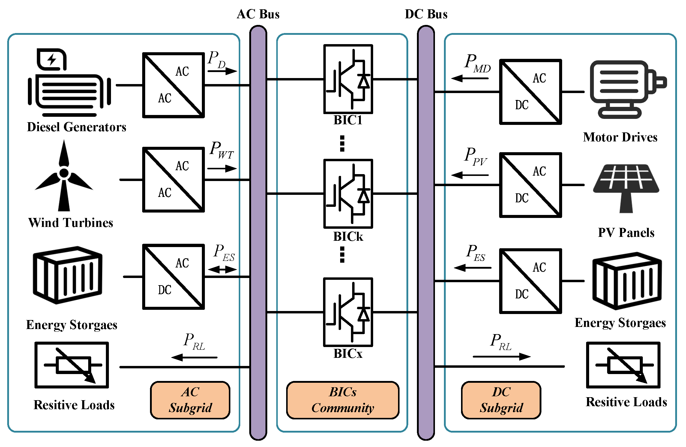
The simplified structure of the AC and DC subgrids are illustrated in Figure 1, respectively. In every AC and DC subgrid, each DG operates under droop control.
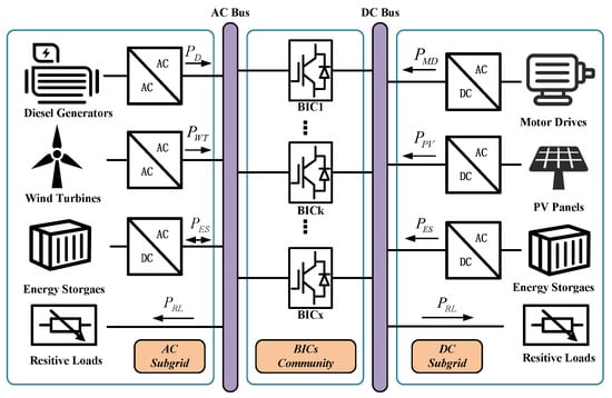
Figure 1.
Typical configuration of a HMG.
For conventional power systems, the droop characteristic of AC microgrids is as shown below:
where and are the upper limit of the frequency and the upper limit of the voltage amplitude for each DG in the AC subgrid. and are the droop factors. and are active and reactive power, respectively.
In an AC subgrid, complex line impedances may result in reactive and active power control not being fully decoupled. In order to solve this issue, a method is used that employs virtual impedance to adjust the output impedance of DGs, which mainly involves keeping the inductive part unchanged to ensure that the droop control remains effective. In addition, the frequency is consistent throughout the AC subgrid, and each DG contributes power proportionally according to its own rated power. However, due to the differences in terminating impedance between different DGs and the AC bus, the voltage drop may be different, and thus the error in reactive power allocation will always exist. Control methods for improving reactive power allocation are reported in the related literature [23]. However, because reactive power is limited to the AC side only and cannot occur in the DC subgrid, these methods are not discussed in this paper. Instead, this paper focuses on the energy flow between two subgrids. Compared with the droop characteristics of the AC microgrid, DC microgrids lack AC frequency and reactive power, so DC microgrids have simpler droop control.
where is the voltage maximum value of the jth DG of the DC subgrid. is the DC droop factor.
The power between the DC DG can also be distributed proportionally as reactive power in the AC subgrid. However, the purpose of this paper is to implement a distributed control method for parallel BICs and GPS in HMGs.
2.2. HMG Primary Unified Control
According to the droop formula of the subgrid in Section 2.1, the AC bus frequency and DC bus voltage represent the sum active power of the main voltage sources of the AC and DC subgrid, respectively. To combine AC droop characteristics and DC droop characteristics in the same dimension, the AC bus frequency f and DC bus voltage can be normalized as [24]:
where and are the normalized f and , and are the nominal values of f and .
In this paper, and . Normalized values indicate the state of the AC and DC subgrids, in the range of [−1, 1] after the same dimension.
According to (4) and (5), the droop characteristics of each AC or DC DG in the active power domain can be derived from (1) and (3). The sum for all DGs in each subgrid droop equation reflects the droop characteristics of the subgrid bus, which are as shown below:
where m and n are the amount of AC and DC DGs and and are the total power output from the DG in the AC and DC side, respectively. Considering the power flowing in bi-directions on the BIC, (6) and (7) become:
where and are the loads in the AC and DC subgrid, respectively.
After normalization, when ,, indicating that the subgrid is lightly loaded; when ,, indicating that the subgrid is overloaded; when ,, indicating that the subgrid is in the stable state.
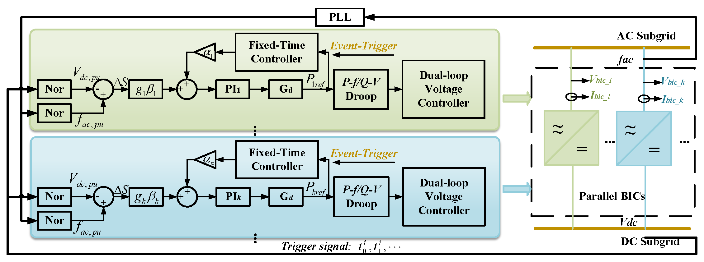
As can be seen, the operating trend of the HMG is that the normalized frequency of the AC side is the same as the normalized voltage of the DC side; thus, the control objective of the BIC is = , as shown in Figure 2. In order to realize this control objective, the difference between and can be passed through the PI controller, and the output result of the PI controller indicates the power to be transmitted by the BIC. Definition is as follows:
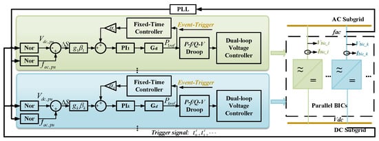
Figure 2.
Overall structure of the proposed controlled HMG parallel BICs.
Therefore, the BIC does not need to know the information of DGs and load inside the subgrid, but only needs to control and equally, so as to realize the purpose of AC/DC subgrids as mutual backup and GPS.
When the system meets the condition =, the power transmitted by the BIC can be expressed from (8) and (9) as follows:
where , .
In this operation, BIC can be regarded as the load of the DC subgrid, and BIC can also be regarded as the load of the AC subgrid. For HMGs, the power not generated by the jth DG in the AC subgrid will be supplied by the ith DG in the DC subgrid according to its rated capacity. The droop control characteristics (1) and (3) of the AC and DC subgrid are therefore updated as:
The droop characteristics of the AC subgrid and DC subgrid equivalent to the bus can be expressed as follows:
This can be obtained by combining Equations (12) and (13):
As , , substituting into (13), it can be obtained as follows:
It can be concluded that the output variation of the DG in the subgrid is proportional to its own rated capacity, which means the GPS is perfectly realized.
3. Power-Sharing Control Strategy with Fixed-Time Event-Triggered Control
In this section, a novel fixed-time power-sharing control method based on event-triggered control is proposed. A method for estimating the maximum stabilization time is also provided.
3.1. Graph Theory and Some Lemmas
Let G be an undirected graph with N agents, where the graph is represented as . Here, denotes the set of nodes, and is the set of edges. An edge implies that node i is able to receive information from node j, and vice versa, making agents i and j neighbors. The consistency matrix is a square matrix of size , where the elements are defined as . Next, we define the degree matrix D, a diagonal matrix , where is the degree of the node i and is given by The Laplacian matrix L of the graph G is then expressed as . For a graph to be considered connected, there must be a route between any two nodes.
Remark 1.
The adjacency matrix A and the Laplace matrix L of an undirected graph are symmetric matrices. Furthermore, for a connected graph, the Laplacian matrix L has exactly one zero eigenvalue, with the corresponding eigenvector being a vector of all ones.
Lemma 1
([25]). A connected undirected graph G, which satisfies the following properties:
where and L is a positive semi-definite matrix. Suppose that the eigenvalues of L are ordered as , with being the second smallest and satisfying . Moreover, if , it follows that
Lemma 2
([26]). Consider a continuous radial unconstrained function where any of its solutions meet
where , , and . The system can achieve stabilization in setting time. The settling time T is bounded by
Lemma 3
([27]). Let . Then, we have
and
3.2. Fixed-Time Event-Triggered Power-Sharing Control
In Section 2.2, the energy flow between the HMG can be formulated as for power transfer through the parallel BICs. As shown in Figure 2, in order to avoid the overloading of individual BICs in the HMG, it is taken as a control objective that the reference powers of all BICs are proportional to their respective BIC ratings, and the sum of the reference powers of all BICs is equal to the :
As emphasized earlier, GPS implementations require the measurement of the and the . Since the frequency is consistent everywhere in an AC subgrid, each BIC can receive through the PLL and thus determine the AC subgrid status. However, the BIC cannot sense locally because of the line impedance between the BIC and the DC bus. In order to make measurements, , an additional sensor must be placed on the DC bus. In addition, the communications phase among the BICs should remain simple to avoid over-complication. It is essential to ensure high scalability for the ease of modular BICs. In these conditions, all BICs reach a consensus with their neighbors by collecting information from them. If a BIC fails, the fixed-time-based event-triggered method ensures the continuous operation of the BIC cluster and enhances the Plug-and-Play (PnP) capability. Furthermore, the fixed-time stabilization of the system ensures that all BICs reach consensus within a setting time, no matter the initial conditions or network size, which enhances system robustness and ensures reliable operation even during transitions.
In order to realize the above two control objectives, this paper designs the following control strategy for the BIC:
where ; , , and are constants greater than zero; and are odd numbers greater than zero.
The error of calculation of agent i is expressed as below:
Then, is expressed as follows:
The event-triggered function for the ith agent is as follows:
where . For each agent, the event updates when . The control rule of agent i is updated at event time .
Theorem 1.
For MASs with parallel BICs, continuous communication consensus with fixed-time event triggering can be achieved when the following conditions are met:
There is a known constant ξ bigger than zero. The maximum setting time T meets:
Proof of Theorem 1.
The Lyapunov functional is set as:
Based on Lemma 1, the conclusions are drawn as follows:
where and are the maximum and second minimum eigenvalues of the matrix L, respectively.
In the following context, it is necessary to apply the concept of the Filipov solution [28].
Its first order derivative with regard to time is
When inequality (24) holds, inequality (28) becomes:
According to Lemma 2, we can find that , , , and . The stabilization time T satisfies the following conditions:
□
Theorem 2.
For MASs consisting of multiple BICs, there is no Zeno behavior
Proof of Theorem 2.
According to (21), one has:
where
and denotes the latest event time of agent j; since , it follows that:
According to the triggering condition (23), the next agent i event-triggered before or equivalently , one has:
which yields with .
□
The use of sign functions in control systems often leads to discontinuities near the zero point. The discontinuity of the sign function at the zeros may lead to high-frequency oscillations in the system, and thus to instabilities such as chattering. When the sign function is used in control systems, especially when the error is close to zero, frequent switching behavior may lead to negative phenomena. In order to avoid chattering caused by the sign function, a saturation function can be used as an alternative in the future. This can significantly reduce the high-frequency switching problem due to discontinuities in the system. By using saturation functions, discontinuities that cause chattering and damage to the equipment can be effectively avoided.
Remark 2.
Unlike finite-time stabilization, the fixed-time stabilization control allows us to easily adjust the controller gain according to (30) to achieve the desired stabilization rate. Therefore, strict stabilization time requirements can be met in practical situations.
For more accurate modeling, add the delay term to the controller.
4. Simulation Results and Analysis
In this section, an islanded HMG consisting of four BICs is simulated, and four simulation cases are studied to verify the validity of the proposed fixed-time event-triggered power-sharing control. The diagram of the secondary control structure is described in Figure 2, and the communication topology can be represented as L = [3, −1, −1, −1; −1, 3, −1, −1; −1, −1, 3, −1; −1, −1, −1, 3].
The line parameters and main control parameters are the basis of the islanded HMG model. To connect the AC and DC subgrid and ensure proper operation of the BIC, the nominal voltage of the DC bus should be larger than 311 × 2 = 622 [29], and the reference value of DC voltage selected in this paper is 700 V. In addition, the DC bus voltage has a deviation of 10 V from the rated voltage. In the BIC control, the AC frequency can be observed with a conventional PLL. As described in ref. [2], the PLL acts to generate a transfer function from the measured frequency to the frequency used for BIC control. This PLL function essentially acts as a filter and does not create any stabilization problems for the overall HMG. Based on the HMG of [30], Table 1 summarizes the main parameters of the other line and control system.

Table 1.
System parameters.
4.1. Case 1: Load Testing
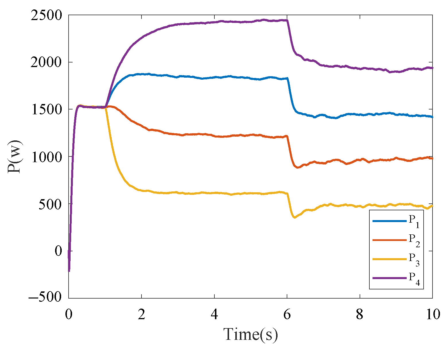
Under controller (19), the parameters are chosen as , , , , and . The parameters meet condition (24). Based on Theorem 1, the maximum settling time s is obtained. To verify the power-sharing performance of the proposed strategy, the fixed-time event-triggered power-sharing control is applied with the islanded HMG. The initial DC and AC loads are set to 0.5 kW and 7 kW, respectively, secondary control is initiated at s, and the DC side load increases from 0.5 kW to 1 kW at s. In addition, control experiments are set up to demonstrate that the control strategy proposed in this paper has a much faster convergence rate compared to the traditional power-sharing control. The control group adopts the controller from ref. [2], with initial DC and AC loads set to 0.5 kW and 7 kW, respectively, secondary control is initiated at s, and the DC side load increases from 0.5 kW to 1 kW at s.
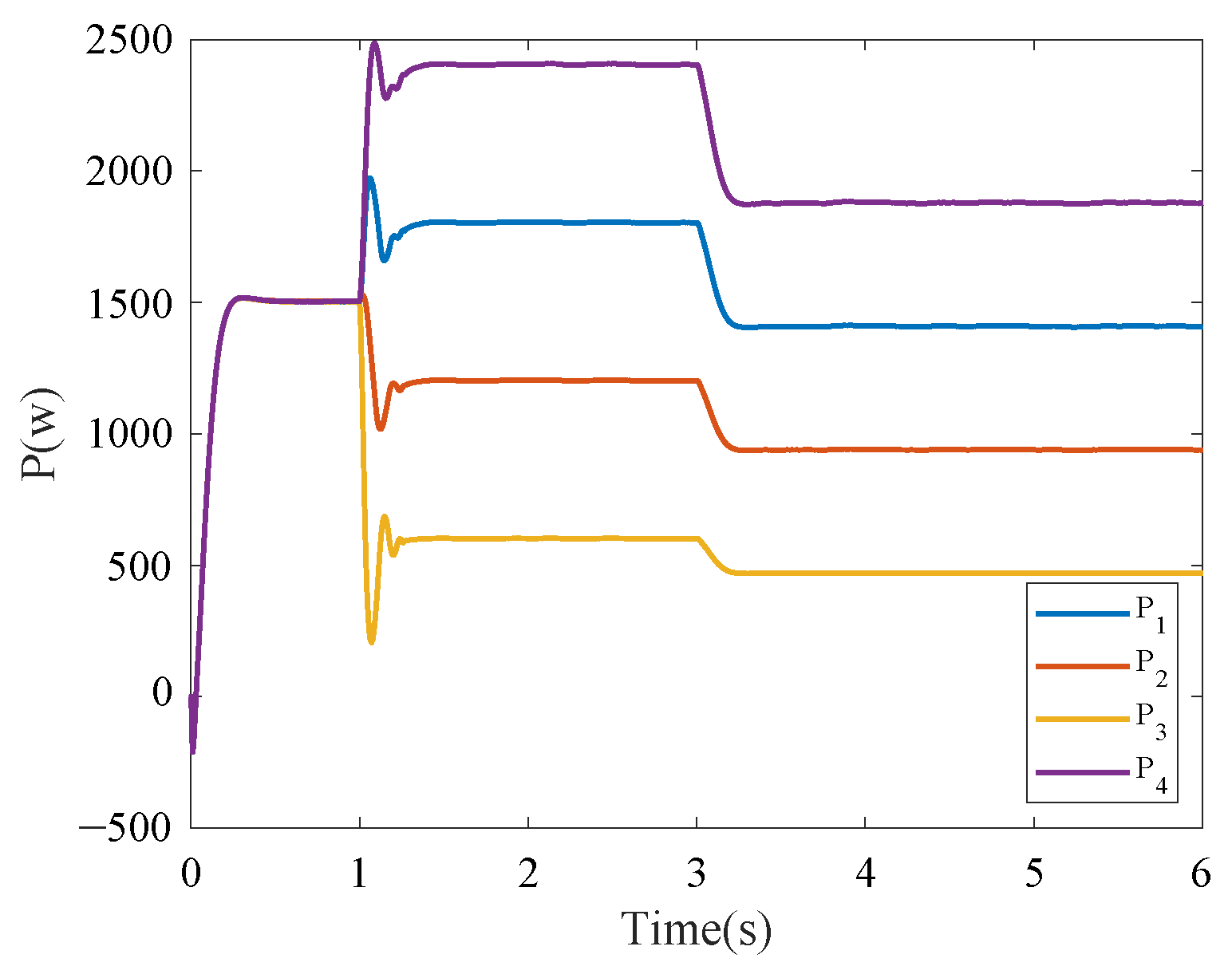
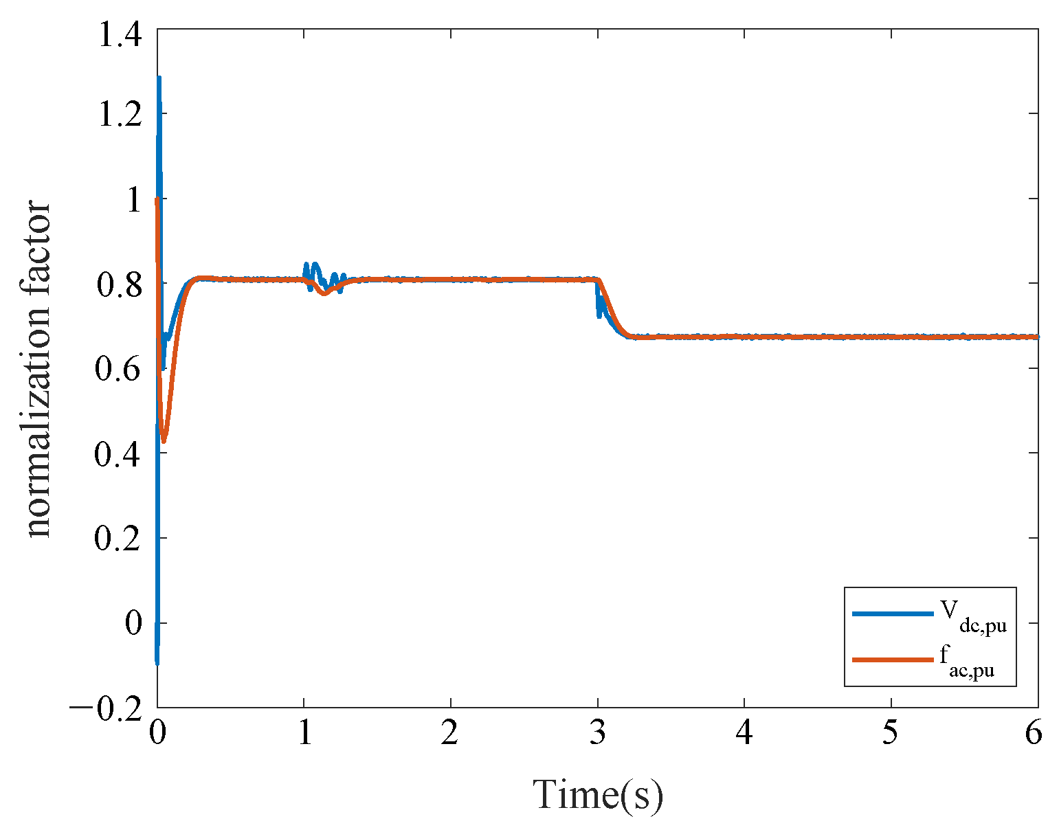
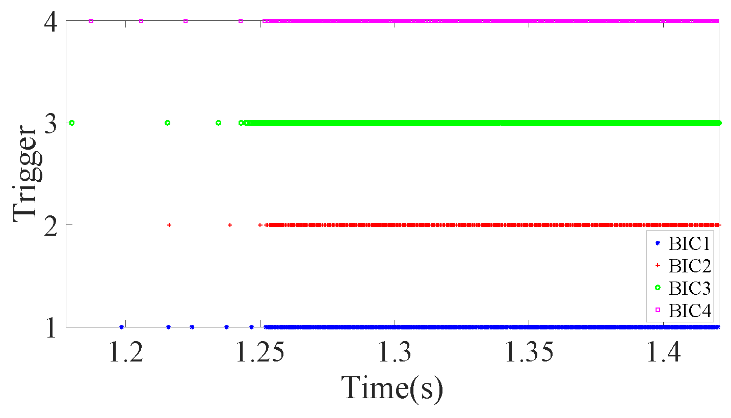
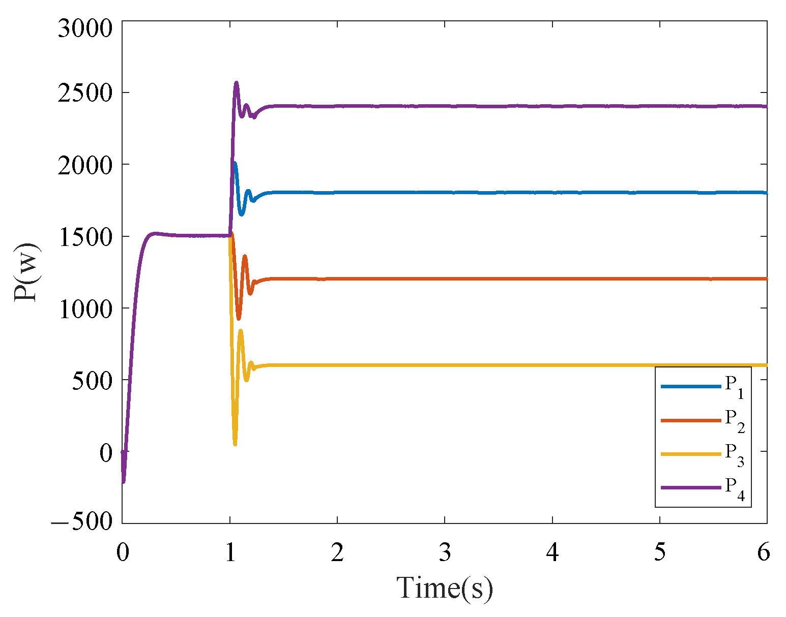
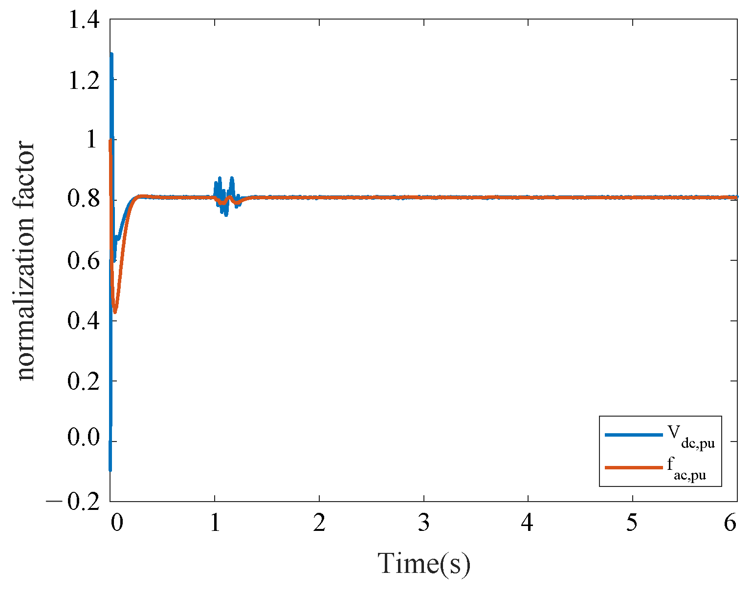
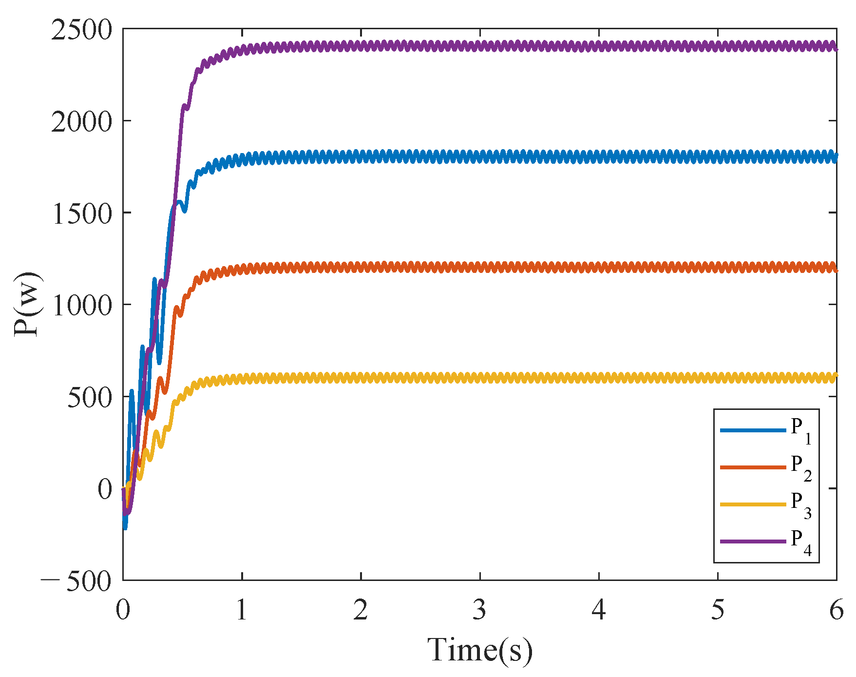
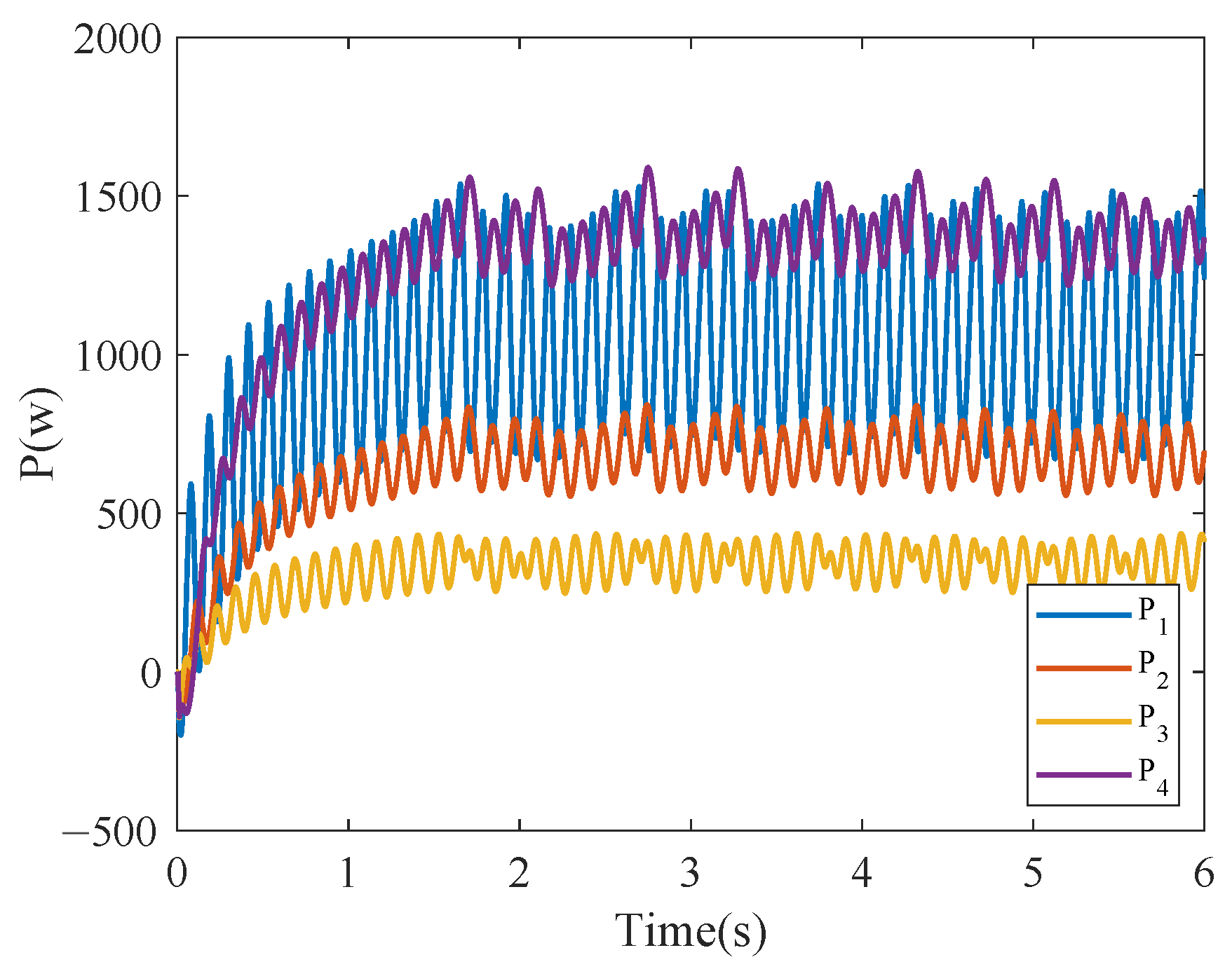
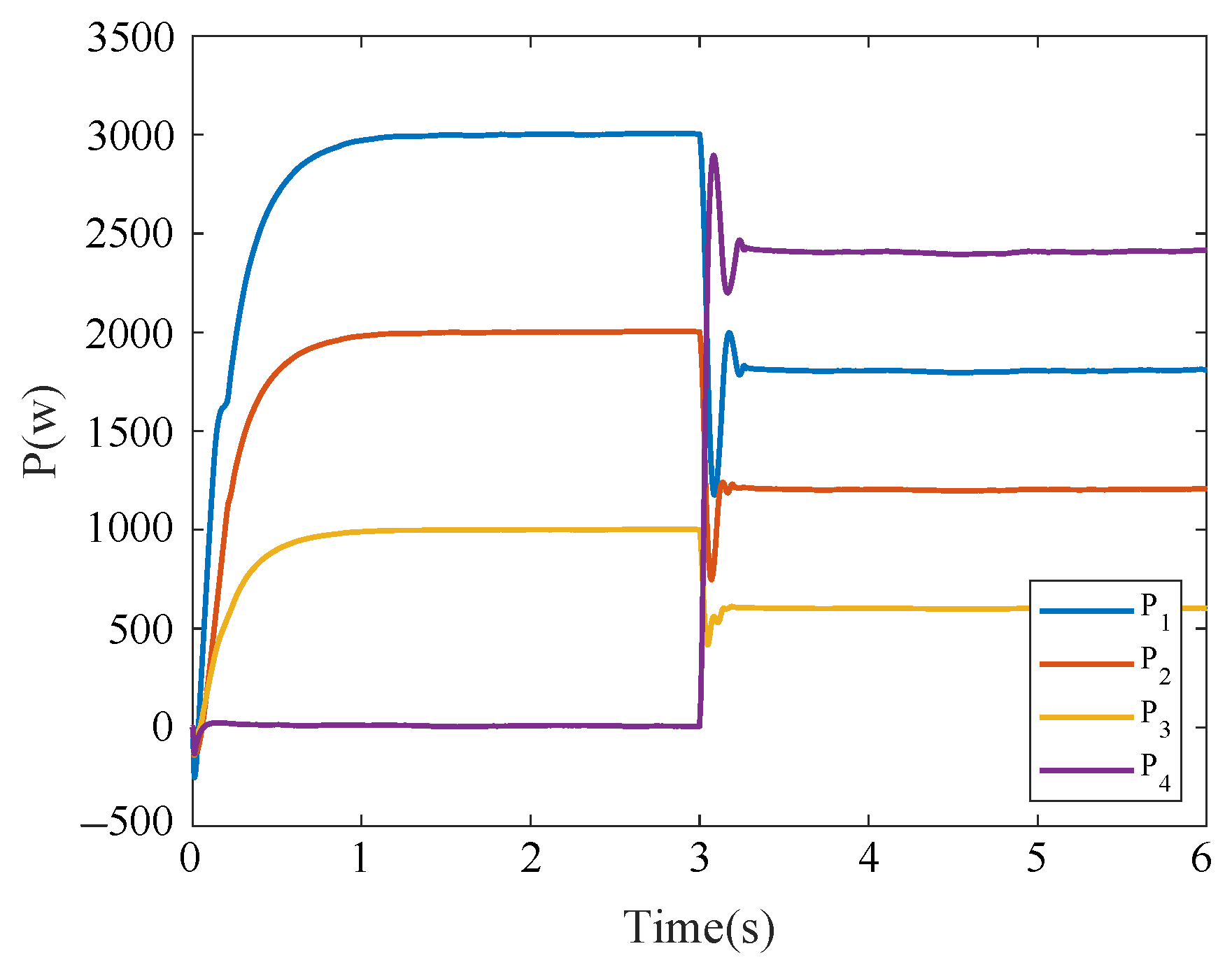
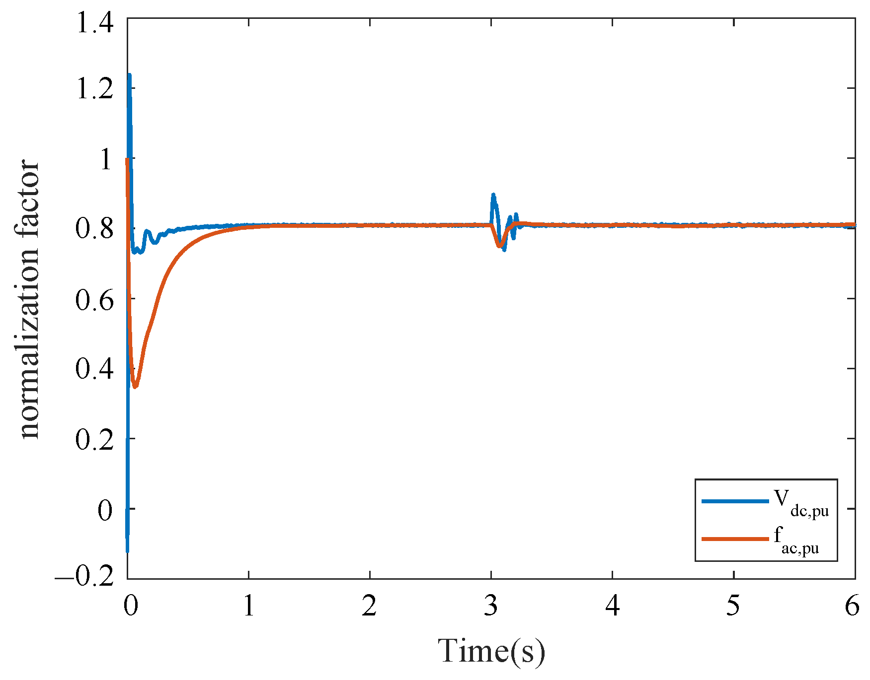
The simulation results in this case are shown in Figure 3, where it can be seen that, at s, only the first level of control acts on the BICs, and each BIC transmits 1.5 kW of power from the DC side to the AC measurement, respectively. At s, a fixed-time event-triggered controller is activated, and all BICs transmit power values that stabilize within the settling time, and the ratio of 3:2:1:4 is maintained. The DC side load is increased to 1 kW at s to study the effect of load variation on system stability. The transmitted power of all BICs still returns to stability within the settling time. The normalized droop coefficients of the AC and DC microgrid remain consistent and still restored to be consistent within the settling time after the load change, as seen in Figure 4. Furthermore, as shown in the event-triggered moments in Figure 5, with the event-triggered control, the communication frequency of the system decreases, which greatly reduces the communication bandwidth and the update frequency of the controller. Compared with the conventional controller in Figure 6, the fixed-time consensus control strategy proposed in this paper has a faster convergence rate.
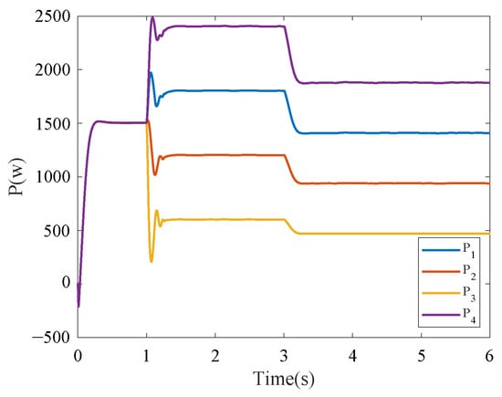
Figure 3.
Transmission power of each BIC applying the proposed fixed-time event-triggered consensus in Case 1.
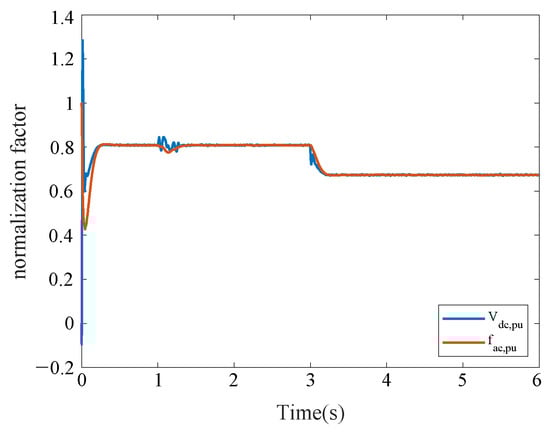
Figure 4.
Normalization factors for AC and DC subgrids in Case 1.
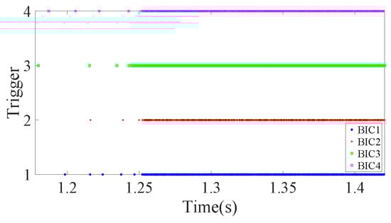
Figure 5.
Moment of event-trigger for each BIC in Case 1.
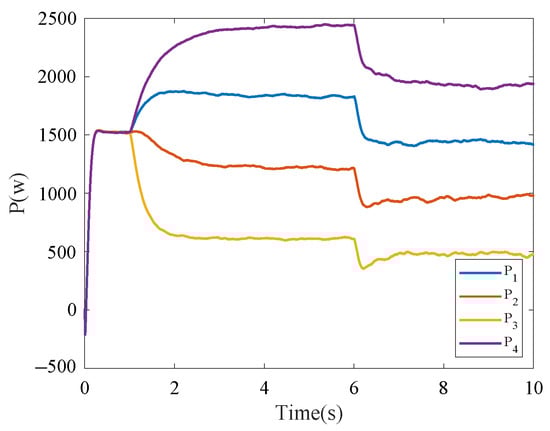
Figure 6.
Transmission power of each BIC for infinite time consensus in Case 1.
Therefore, the fixed-time event-triggered consensus control proposed in this paper can realize power sharing among BICs under load transformation and has a faster convergence rate compared to infinite-time consensus.
4.2. Case 2: Communication Link Fault Testing
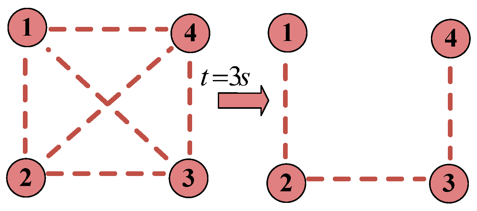
Note that the parallel BIC under the proposed fixed-time event-trigger method is robust to communication link failures since the communication environment is open. Therefore, the new case is designed. In this case, all parameters are the same as in Case 1. At s, the communication between BIC1 and BIC4 breaks, and the communication topology changes, as presented in Figure 7.
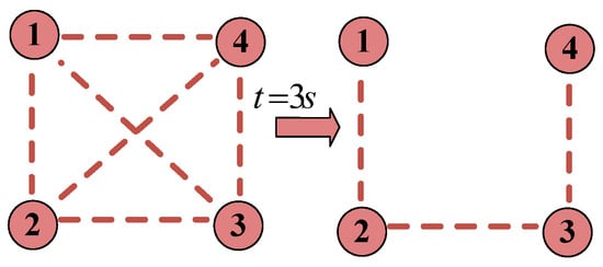
Figure 7.
Communication topology in Case 2.
Figure 8 illustrates the transmission power values of each BIC in Case 3, and Figure 9 illustrates the normalization factor for the AC and DC subgrid in Case 3. It can be seen that the control performance of the system is not affected despite the sudden change in the communication link due to communication. After a communication link failure, the BICs still transmit power in the ratio of 3:2:1:4. This is because the communication link remains connected even if a communication link failure occurs.
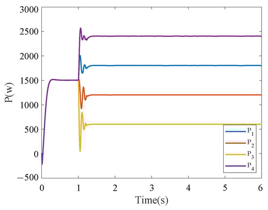
Figure 8.
Transmission power of each BIC applying the proposed fixed-time event-triggered consensus in Case 2.
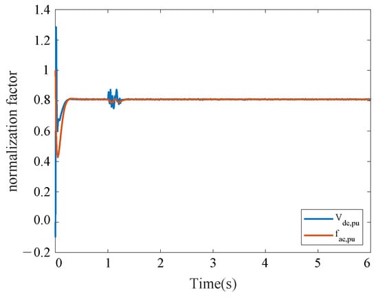
Figure 9.
Normalization factors for AC and DC subgrids in Case 2.
Centralized control can lead to a single point of failure; this means that, when one agent fails, the whole system goes down. In contrast, the distributed faulting proposed in this paper helps to increase resilience to communication loss. In Figure 3, if a communication failure occurs, the integrator in the system will record the power reference generated before the communication failure and, until troubleshooting, the kth BIC will continue to pass energy between the two subgrids. For HMGs, GPS and power sharing between four BICs can be realized without any impact only if their communication graph is in spanning tree form.
4.3. Case 3: Effect of Delay on System Stability
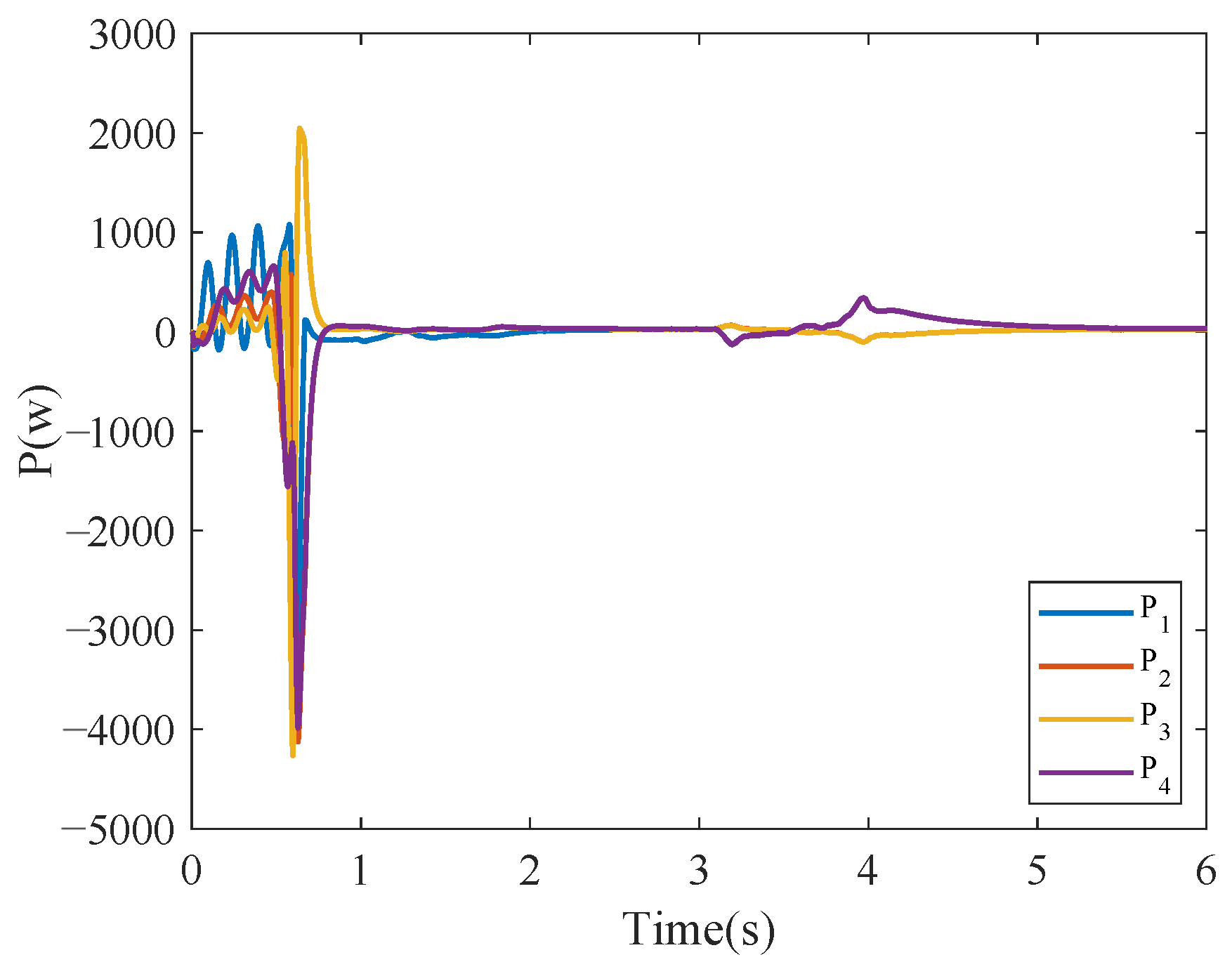
Notably, the effect of time delay on the stability of the system is obtained from the previous analysis, and the communication delay between BICs is unavoidable in a multi-BIC system. The parameter , which represents the communication delay, needs to be studied as a key parameter affecting the stability of the system. By varying the magnitude of , the maximum magnitude of communication delay is obtained so that the system can converge under this communication network, which can be of great significance for further optimization of the control strategy. The communication delay containing different time durations in the control is simulated and verified in simulink, and the following results are obtained. Case 4 is set to start four BICs at the same time at s. Setting the communication delay in the control loops of all four BICs, the power waveforms transmitted by the BICs as illustrated in Figure 10, Figure 11 and Figure 12 when is 5 ms, 10 ms, and 20 ms. As increases, the system tends to become unstable. In order to make sure that the HMG under study operates in a stable state, the communication delay of the system cannot be too large.
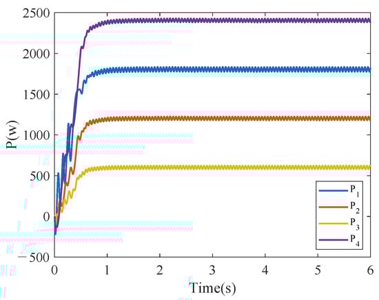
Figure 10.
Transmission power of each BIC applying the proposed fixed-time event-triggered consensus when ms.
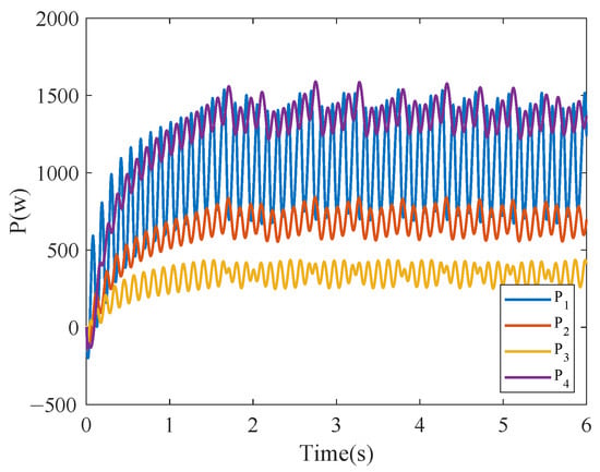
Figure 11.
Transmission power of each BIC applying the proposed fixed-time event-triggered consensus when ms.
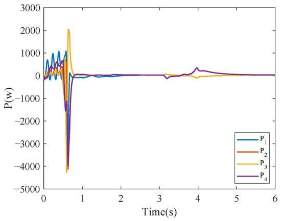
Figure 12.
Transmission power of each BIC applying the proposed fixed-time event-triggered consensus when ms.
4.4. Case 4: Plug-and-Play Capability
Note that the number of BICs connecting the AC and DC subgrid is actually variable. Thus, a new case is studied that shows the PnP capability of the BICs.
The control parameters are the same as in Case 1. Initially, there are three BICs connected in parallel in the islanded HMG. Before s, the proposed secondary control is not applied to BIC4. After s, BIC4 is connected to the islanded HMG and activates the proposed secondary control.
Figure 13 illustrates the value of power transmitted by each BIC in Case 3. Between s, BIC1, BIC2, and BIC3 transmit power in the ratio of 3:2:1. After s, BIC4 is connected to the HMG and the power is transmitted by BIC1, BIC2, BIC3, and BIC4 in the ratio 3:2:1:4. The total power transmitted by the four BICs remains unchanged before and after BIC4 is connected. Figure 14 illustrates the normalization factors of the AC and DC subgrid, which remain consistent before and after the plug-in of BIC4. Therefore, it can be demonstrated that the BICs applying the proposed fixed-time event-triggered consensus control method have good robustness and responsiveness to the connection and reconnection of the system.
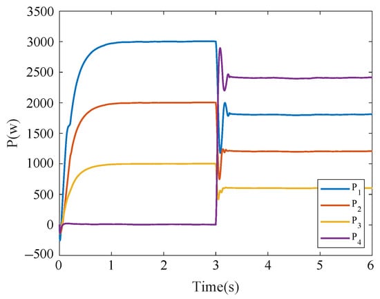
Figure 13.
Transmission power of each BIC applying the proposed fixed-time event-triggered consensus in Case 4.
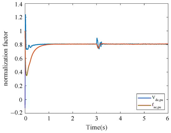
Figure 14.
Normalization factors for AC and DC subgrids in Case 4.
5. Experitment Results
In this section, the hardware-in-the-loop (HIL) experiments are tested to further verify the performance of the fixed-time consensus control based on event-triggered control for islanded HMG parallel BICs through the StarSim HIL realtime simulator. In this HIL experiment, the controller, which includes four BICs, is used in the DSP (TMS320F28335) controller when the other parts of the system are simulated in the HIL simulator. This system is shown in Figure 15.
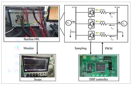
Figure 15.
The structure of the experiment test system.
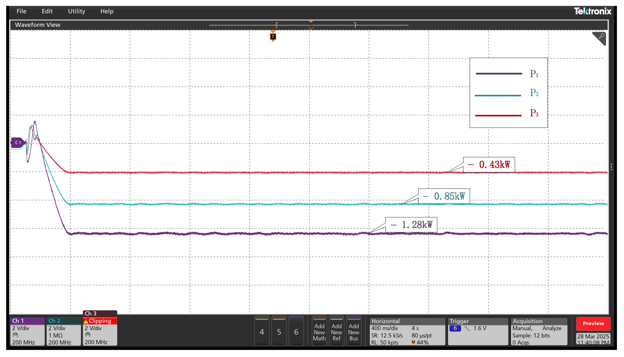
The experiments were tested in the StarSim HIL simulator. The equipment is manufactured and designed by National Instruments. Meanwhile, a new case was designed to better demonstrate the performance of the event-triggered fixed-time power-sharing-based control strategy and to demonstrate the power bi-directional flow function of the BIC. The DC loads are set as 7 KW, AC load as 2 KW, and other parameters are the same as in Case 1. At s, the system utilizes the proposed fixed-time event-triggered control strategy, and the transmission power of each BIC of this system is shown in Figure 16. The transmitted power is negative, indicating that the power is transmitted from the AC measurement to the DC side, and the four BICs transmit the power according to the ratio of 3:2:1. It is demonstrated that the power can flow bi-directionally in the BICs.
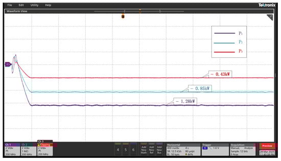
Figure 16.
The transmitted power for each BIC in the test system.
6. Conclusions
Since the conventional power-sharing control of HMG parallel BICs has been stabilized in infinite time, the controller is updated frequently. Thus, the convergence speed and communication bandwidth reduction have been considered in this paper. By the concept of MASs, the power-sharing control problem has been transformed into a consensus problem with uncertain nonlinear MASs. Then, a novel method in the estimation of maximum setting time has been provided, which lays the foundation for designing fixed-time control strategies. Based on this, an event-triggered control method has been provided to effectively reduce the control update frequency. Finally, the effectiveness of the fixed-time power-sharing control strategy based on event-triggered control has been verified by simulation examples and experiments. Note that network attacks, actuator failures, and other problems have been ignored in this paper. In the future, we will work on researching and proposing event-triggered control-based fixed-time power-sharing control for BIC under cyber-attack.
Author Contributions
Writing—original draft, J.W.; methodology, J.W.; Conceptualization, S.L.; Resources, S.L.; Data curation, B.Q.; Visualization, C.J.; Software, Z.S.; Supervision, J.X.; Validation, J.X.; Writing—review editing, J.X. All authors have read and agreed to the published version of the manuscript.
Funding
This research received no external funding.
Data Availability Statement
The original contributions presented in this study are included in the article material. Further inquiries can be directed to the corresponding author(s).
Conflicts of Interest
Author Siyu Lyu was employed by China Huaneng Group Co., Ltd and Huaneng Nuclear Power Development Co., Ltd. The remaining authors declare that the research was conducted in the absence of any commercial or financial relationships that could be construed as a potential conflict of interest.
References
- Shen, X.; Tan, D.; Shuai, Z.; Luo, A. Control Techniques for Bidirectional Interlinking Converters in Hybrid Microgrids: Leveraging the advantages of both ac and dc. IEEE Power Electron. Mag. 2019, 6, 39–47. [Google Scholar] [CrossRef]
- Lin, P.; Wang, P.; Jin, C.; Xiao, J.; Li, X.; Guo, F.; Zhang, C. A Distributed Power Management Strategy for Multi-Paralleled Bidirectional Interlinking Converters in Hybrid AC/DC Microgrids. IEEE Trans. Smart Grid 2019, 10, 5696–5711. [Google Scholar] [CrossRef]
- Liu, J.; Yu, Y.; Wang, Q.; Sun, C. Fixed-time event-triggered consensus control for multi-agent systems with nonlinear uncertainties. Neurocomputing 2017, 260, 497–504. [Google Scholar] [CrossRef]
- Gupta, A.; Doolla, S.; Chatterjee, K. Hybrid AC–DC Microgrid: Systematic Evaluation of Control Strategies. IEEE Trans. Smart Grid 2018, 9, 3830–3843. [Google Scholar] [CrossRef]
- Yoo, H.J.; Nguyen, T.T.; Kim, H.M. Consensus-Based Distributed Coordination Control of Hybrid AC/DC Microgrids. IEEE Trans. Sustain. Energy 2020, 11, 629–639. [Google Scholar] [CrossRef]
- Lu, X.; Guerrero, J.M.; Sun, K.; Vasquez, J.C.; Teodorescu, R.; Huang, L. Hierarchical Control of Parallel AC-DC Converter Interfaces for Hybrid Microgrids. IEEE Trans. Smart Grid 2014, 5, 683–692. [Google Scholar] [CrossRef]
- Xiao, H.; Luo, A.; Shuai, Z.; Jin, G.; Huang, Y. An Improved Control Method for Multiple Bidirectional Power Converters in Hybrid AC/DC Microgrid. IEEE Trans. Smart Grid 2016, 7, 340–347. [Google Scholar] [CrossRef]
- Eghtedarpour, N.; Farjah, E. Power Control and Management in a Hybrid AC/DC Microgrid. IEEE Trans. Smart Grid 2014, 5, 1494–1505. [Google Scholar] [CrossRef]
- Qi, G.; Chen, A.; Chen, J. Improved control strategy of interlinking converters with synchronous generator characteristic in islanded hybrid AC/DC microgrid. CPSS Trans. Power Electron. Appl. 2017, 2, 149–158. [Google Scholar] [CrossRef]
- Sun, K.; Wang, X.; Li, Y.W.; Nejabatkhah, F.; Mei, Y.; Lu, X. Parallel Operation of Bidirectional Interfacing Converters in a Hybrid AC/DC Microgrid Under Unbalanced Grid Voltage Conditions. IEEE Trans. Power Electron. 2017, 32, 1872–1884. [Google Scholar] [CrossRef]
- Bhat, S.P.; Bernstein, D.S. Finite-Time Stability of Continuous Autonomous Systems. SIAM J. Control Optim. 2006, 38, 751–766. [Google Scholar] [CrossRef]
- Wang, P.; Gong, P. A Continuous Algorithm for Finite-Time Consensus of Disturbed Fractional-Order Multiagent Systems Over Digraphs. IEEE Trans. Circuits Syst. II Express Briefs. 2023, 70, 4148–4152. [Google Scholar] [CrossRef]
- Cortés, J. Finite-time convergent gradient flows with applications to network consensus. Automatica 2006, 42, 1993–2000. [Google Scholar] [CrossRef]
- Hui, Q.; Haddad, W.M.; Bhat, S.P. Finite-Time Semistability and Consensus for Nonlinear Dynamical Networks. IEEE Trans. Autom. Control 2008, 53, 1887–1900. [Google Scholar] [CrossRef]
- Wang, L.; Xiao, F. Finite-Time Consensus Problems for Networks of Dynamic Agents. IEEE Trans. Autom. Control 2010, 55, 950–955. [Google Scholar] [CrossRef]
- Li, S.; Du, H.; Lin, X. Finite-time consensus algorithm for multi-agent systems with double-integrator dynamics. Automatica 2011, 47, 1706–1712. [Google Scholar] [CrossRef]
- Liu, J.; Zhang, Y.; Sun, C.; Yu, Y. Fixed-time consensus of multi-agent systems with input delay and uncertain disturbances via event-triggered control. Inf. Sci. 2019, 480, 261–272. [Google Scholar] [CrossRef]
- Sharghi, A.; Baradarannia, M.; Hashemzadeh, F. Leader-Follower Fixed-Time Consensus for Multi-agent Systems with Heterogeneous Non-linear Inherent Dynamics. In Proceedings of the 2016 3rd International Conference on Soft Computing & Machine Intelligence (ISCMI), Dubai, United Arab Emirates, 23–25 November 2016; pp. 224–228. [Google Scholar] [CrossRef]
- Dimarogonas, D.V.; Johansson, K.H. Event-triggered control for multi-agent systems. In Proceedings of the 48h IEEE Conference on Decision and Control (CDC) Held Jointly with 2009 28th Chinese Control Conference, Shanghai, China, 15–18 December 2009; pp. 7131–7136. [Google Scholar] [CrossRef]
- Zhang, J.; Zhao, Z.; Jin, X.; Wang, M.; Huang, N.; Chen, Z.; Zhang, Y. Distributed event-triggered control for multi-agent systems with unknown data. In Proceedings of the 2022 41st Chinese Control Conference (CCC), Hefei, China, 25–27 July 2022; pp. 4886–4890. [Google Scholar] [CrossRef]
- He, J.; Li, Y.W. Analysis, Design, and Implementation of Virtual Impedance for Power Electronics Interfaced Distributed Generation. IEEE Trans. Ind. Appl. 2011, 47, 2525–2538. [Google Scholar] [CrossRef]
- Wang, J.; Dong, C.; Jin, C.; Lin, P.; Wang, P. Distributed Uniform Control for Parallel Bidirectional Interlinking Converters for Resilient Operation of Hybrid AC/DC Microgrid. IEEE Trans. Sustain. Energy 2022, 13, 3–13. [Google Scholar] [CrossRef]
- Gupta, Y.; Parganiha, N.; Rathore, A.K.; Doolla, S. An Improved Reactive Power Sharing Method for an Islanded Microgrid. IEEE Trans. Ind. Appl. 2021, 57, 2954–2963. [Google Scholar] [CrossRef]
- Rodriguez-Diaz, E.; Chen, F.; Vasquez, J.C.; Guerrero, J.M.; Burgos, R.; Boroyevich, D. Voltage-Level Selection of Future Two-Level LVdc Distribution Grids: A Compromise Between Grid Compatibiliy, Safety, and Efficiency. IEEE Electrif. Mag. 2016, 4, 20–28. [Google Scholar] [CrossRef]
- Olfati-Saber, R.; Murray, R. Consensus problems in networks of agents with switching topology and time-delays. IEEE Trans. Autom. Control 2004, 49, 1520–1533. [Google Scholar] [CrossRef]
- Polyakov, A. Nonlinear Feedback Design for Fixed-Time Stabilization of Linear Control Systems. IEEE Trans. Autom. Control 2012, 57, 2106–2110. [Google Scholar] [CrossRef]
- Zuo, Z.; Tie, L. Distributed robust finite-time nonlinear consensus protocols for multi-agent systems. Int. J. Syst. Sci. 2016, 47, 1366–1375. [Google Scholar] [CrossRef]
- Hu, S. Differential equations with discontinuous right-hand sides. J. Math. Anal. Appl. 1991, 154, 377–390. [Google Scholar] [CrossRef]
- Peyghami, S.; Mokhtari, H.; Blaabjerg, F. Autonomous Operation of a Hybrid AC/DC Microgrid With Multiple Interlinking Converters. IEEE Trans. Smart Grid 2018, 9, 6480–6488. [Google Scholar] [CrossRef]
- Fang, J.; Li, X.; Li, H.; Tang, Y. Stability Improvement for Three-Phase Grid-Connected Converters Through Impedance Reshaping in Quadrature-Axis. IEEE Trans. Power Electron. 2018, 33, 8365–8375. [Google Scholar] [CrossRef]

Disclaimer/Publisher’s Note: The statements, opinions and data contained in all publications are solely those of the individual author(s) and contributor(s) and not of MDPI and/or the editor(s). MDPI and/or the editor(s) disclaim responsibility for any injury to people or property resulting from any ideas, methods, instructions or products referred to in the content. |
© 2025 by the authors. Licensee MDPI, Basel, Switzerland. This article is an open access article distributed under the terms and conditions of the Creative Commons Attribution (CC BY) license (https://creativecommons.org/licenses/by/4.0/).