Abstract
The strategic positioning of heating and cooling segments within complex non-rectangular geometries has emerged as a critical engineering challenge across multiple industries in thermal management systems for electronic components. This analysis presents a numerical inspection of buoyancy-driven convective flow and thermal transport mechnisms of nanofluids in a parallelogrammic porous geometry. A single discrete heating–cooling segment has been placed along the slanting surfaces of the geometry. The mathematical model is formulated utilizing Darcy’s law, incorporating the Tiwari and Das approach to characterize the thermophysical properties of the nanofluid. The governing model equations corresponding to the physical process are solved numerically using finite-difference-based alternating direction implicit (ADI) and successive line over-relaxation (SLOR) techniques. Computational simulations are performed for various parametric conditions, including different nanoparticle volume fractions (–), Rayleigh numbers (–), and parallelogram geometry () and sidewall () tilting angles ( and ), while examining the effect of discrete thermal locations. The results reveal a significant decrement in thermal transfer rates with an increasing nanoparticle concentration, particularly at higher Rayleigh numbers. The skewness of the parallelogrammic boundaries is found to substantially influence flow patterns and thermal transport characteristics compared to conventional rectangular enclosures. Further, the discrete placement of heating and cooling sources creates unique thermal plumes that modify circulation patterns within the domain. The predictions suggest profound insights for optimizing thermal management systems by employing nanofluids in non-rectangular porous configurations, with potential applications in geothermal energy extraction, electronic cooling systems, and thermal energy storage devices.
Keywords:
Tiwari and Das model; buoyancy-driven convection; nanofluid-saturated porous envelope; inclined parallelogram geometry; discrete thermal boundary conditions; porous media; numerical method MSC:
80A19; 80M20; 35G61; 76D05; 65H10; 65M06
1. Introduction
Buoyancy-assisted flow motion and thermal transport processes in finite-shaped porous domains represent a critical area of thermal science with profound practical applications. Unlike open-domain flows, convection within bounded porous geometries manifest distinct flow structures, thermal stratification, and recirculation zones, which, in turn, fundamentally alter heat transport mechanisms. In addition, finite-spaced porous geometries represent a critical engineering configuration that maximizes thermal performance in space-constrained applications, such as electronic cooling, building technology, and industrial processes, to mention a few [1,2]. Finite-shaped domains fall into two broad categories: regular-shaped and non-regular-shaped geometries. Non-regular geometries serve unique specialized applications across various engineering disciplines. These irregular domains present significant analytical challenges, particularly due to the fact that their boundaries typically do not align with the coordinate axes. Additionally, they create complex gravitational force interactions from their unconventional shapes. Applications such as biomedical engineering, aerospace components, electronics cooling systems, and energy systems frequently feature intricate geometrical configurations. These characteristics make thermal fluid analysis in non-regular domains particularly demanding in computational studies. Among various non-rectangular conduits, a parallelogrammic domain has potential implementations, such as thermal diodes, compact heat exchangers, the cooling of electronic equipment, and solar thermal systems. The early experimental and theoretical studies on thermal transport in this geometry are from Seki et al. [3] and Hyun and Choi [4]. Later, Baïri and co-researchers [5,6] performed a combined numerical and experimental investigation on transient buoyant-assisted flow and thermal mechanisms in a uniformly and discretely heated–cooled parallelogram-shaped section to comprehend critical thermal behavior patterns, with a particular emphasis on avionics. Thermosolutal transport phenomena in parallelogram-shaped configurations have garnered substantial interest for understanding the complex interplay between thermal and solutal mechanisms under various conditions, particularly numerical examination of mixed convection in ventilated parallelogrammic domains [7] with an air–CO2 mixture, while more recent investigations [8] have extended this work to thermo–solutal–magnetoconvection in tilted porous parallelogrammic domains with discrete heated–cooled segments. It should be noted that the above discussed studies primarily focused on conventional fluids.
The electronics cooling of industrial components faced growing thermal management challenges that could not be adequately addressed by conventional fluids. This led to the development of novel fluids, coined as “nanofluids,” a breakthrough innovation by Choi and colleagues [9]. These specialized fluids consist of nano-sized particles (NPs) dispersed within a base fluid. Their superior heat transfer properties make them particularly valuable for meeting the highly demanding cooling requirements of modern electronic components. Ghalambaz et al. [10] studied convective motion of Cu–water nanofluids (NFs) within the parallelogrammic-shaped porous domain using the Darcy assumption by adopting the Tiwari and Das approach [11]. They predicted that the presence of NPs in the porous structure deteriorated thermal transfer rates due to increased viscosity, despite enhanced thermal conductivity, this effect being more pronounced in low-porosity media and at negative tilt angles. Later, Alsabery et al. [12] analyzed transient buoyant convection in an NF-saturated oblique porous geometry and observed an enhanced thermal dissipation for a thermal non-equilibrium model compared to thermal equilibrium conditions, with water–Ag NF showing superior performance among the four NPs considered. Hussein and Mustafa [13] numerically investigated buoyant-assisted convection in an open parallelogram-shaped cavity with localized bottom heating and observed that the optimal thermal dissipation transfer occurs with the heat source near the left wall at a 60° inclination. A non-homogeneous model for combined free-forced convection in a skewed enclosure revealed elevated thermal transport compared to the homogeneous model, while demonstrating that smaller NPs provide superior thermal transfer performance compared to larger ones [14]. Magneto-mixed convection inside a vented parallelogrammic configuration with injection or suction mechanisms has been examined by Bhuiyan et al. [15]. Their analysis demonstrated enhanced thermal dissipation rates with higher Richardson numbers, while the Hartmann number serves as an effective control parameter for regulating thermal transport phenomena. Yasin et al. [16] investigated magneto-mixed convection in a corrugated parallelogram configuration with a partially heated lower boundary. Their finite element simulation revealed the dominance of forced convective motion at low Richardson numbers, while enhancing the wall undulation amplitude elevates thermal dissipation rates. Recently, Humayoun et al. [17] examined buoyancy-assisted convection inside a porous parallelogram-structured domain under non-uniform temperature conditions. Their predictions revealed enhanced thermal transfer rates with higher Rayleigh and Prandtl numbers and larger inclination angles that decreased with higher Darcy numbers. The above investigations primarily focus on the buoyancy-assisted convection of different NFs in parallelogram-shaped configurations with various constraints, such as magnetic fields, porosity, and curved and vented boundaries.
Among the diverse finite-sized configurations, a differently heated square or rectangular porous domain filled with different NFs demonstrates significant practical relevance across numerous industrial applications. In this direction, Oztop and Abu-Nada [18] numerically examined convective thermal transport in a partially heated rectangular enclosure filled with three different (Cu, Al2O3, and TiO2) NFs. Their results revealed that thermal dissipation elevates with NP concentration, and that the enhancement is more pronounced at low aspect ratios, with Cu NPs providing the maximum heat dissipation improvement. Buoyant-driven convection in square porous domains filled with diverse nanofluids has been investigated by employing Darcy’s law, but different approaches have been used, such as Buongiorno’s model [19] and Tiwari and Das’ model [20]. Their predictions demonstrated that the relative difference in thermal conductivity between nanoparticles and porous media is the key factor determining heat transfer improvement. Alsabery and collaborators [21,22] performed numerical experiments on buoyant thermal transport in porous-NF systems with sinusoidal thermal constraints using finite difference methodology. In their studies of both an inclined square enclosure with a porous NF layer and conjugate thermal transfer with finite wall thickness, they demonstrated that heat transport enhancement varied significantly with geometry inclination angle, porous layer thickness, wall properties, and nanoparticle type, while non-uniform heating substantially increased the overall thermal transfer performance. In our earlier work [23] we numerically analyzed the thermal effects caused by non-uniform heating with a focus on buoyant transport versus entropy generation. The results strongly support the notion that ensemble-tree-based models, specifically gradient boosting models, are an effective means of accurately estimating complex non-linear relationships, especially in comparison to linear, kernel-based approaches and neural networks. Chamkha and Selimefendigil [24] numerically investigated magneto-convection and entropy generation in a square NF-filled porous domain with corrugated walls. They observed that increasing corrugation frequency reduced thermal transfer rates, while the magnetic force suppressed the heat transfer for both flat and corrugated boundaries.
Using Buongiorno’s two-phase model, Alhashash [25] investigated the buoyant motion of nanoliquid in a square porous chamber with a partially heated cylinder. The results showed that thermal transfer rates decreased with increasing heated surface area, but increased with higher NP concentrations. Abed and Al-Damook [26] examined convective transport mechanisms in a square NF-filled porous domain containing three heated tubes. The multi-objective optimization approach suggested an enhanced heat dissipation through the proper selection of geometric and thermophysical parameters. Azad et al. [27] examined the rotational influence of a hot tube on magneto-hydrothermal mechanisms in a square conduit with a localized source containing CNT–water NF and reported an enhanced flow circulation and overall thermal performance with the cylinder’s rotational speed. Investigations inside a shallow chamber packed with metal foam and nano-enhanced PC material reveal that metal foam significantly outperforms nanoparticles for thermal dissipation, with a complete melting time significantly reduced as the foam filling ratio increases [28]. Lakshmi et al. [29] numerically examined the buoyant transport of Cu–water NF within a porous square conduit with different orientations of a centrally located heated rod. Their findings demonstrated that the inclined rod configuration exhibited superior thermal performance compared to horizontal and vertical orientations. Mixed convection in a lid-driven porous configuration with TiO2–water NF revealed that increasing NP volume fraction elevated thermal transfer at lower concentrations, while magnetic field intensity significantly influenced both heat transfer and entropy generation [30]. Vigneshwari et al. [31] investigated the unsteady magneto-convection of TiO2-H2O NF in a partially heated–cooled square porous domain and observed enhanced thermal transport rates with an increase in the heat source/sink parameter.
Researchers have also thoroughly documented how porous structures influence flow dynamics and heat transport performance within diverse irregular geometries, primarily due to the widespread implementation of such configurations across numerous engineering and industrial applications [32,33,34]. An exhaustive review was conducted on buoyant-assisted convection phenomena and the associated thermal transfer characteristics of NFs in various geometries, providing an extensive analysis of the impacts of parameters like Rayleigh, Darcy, and Hartman numbers and NF volume fraction [35,36]. Recent investigations have expanded the understanding of NF convection behavior in locally heated porous domains under various constraints, as evidenced in works examining convection in tilted wavy porous geometries with localized heating [37], square conduits with Casson hybrid nanofluids with classical [38] and sinusoidal heat flux [39], MHD convection in partially cross-heated NF-loaded geometries [40], and vibrational effects on thermosolutal free convection phenomena [41]. Based on a comprehensive review of the established literature concerning diverse porous configurations containing NFs, significant research gaps remain unexplored in understanding the effects of complex geometry, coupled modeling, and discrete thermal boundary conditions. Specifically, no previous studies have investigated the combined influences of the following:
- (a)
- Investigation of parallelogrammic geometry with simultaneous cavity inclination () and sidewall tilting (), creating a unique double-inclination configuration that has not been previously studied.
- (b)
- Implementation of discrete heating/cooling source–sink pairs on inclined walls of the parallelogram, departing from conventional uniform heating or discrete heating on vertical walls.
- (c)
- Integration of a Darcy porous medium framework with a Tiwari and Das nanofluid model for this specific geometric and thermal configuration.
Despite the relevance of such geometry in numerous engineering applications, the effects of orientation angles on buoyant transport characteristics within this domain remain unexplored. This study addresses this knowledge gap by conducting a systematic numerical investigation to elucidate the influence of combined inclination angles and the enclosure, as well as the sidewall, on buoyancy-driven convection and the associated thermal transport mechanisms in a parallelogrammic porous geometry. The primary objective is to establish quantitative relationships between geometric parameters, thermal boundary conditions, and resultant heat dissipation phenomena in this complex configuration.
2. Mathematical Framework
2.1. Description of Geometry
Our analysis examines a porous domain shaped as a parallelogram, illustrated in Figure 1, with its key dimensions and orientation in the Cartesian reference frame. The geometry, characterized by dimensions L (width) and H (height), is oriented at an angle with the axis. The thermal boundary conditions feature a thermal source and sink located on the opposing inclined surfaces. Specifically, there is a higher-temperature source on the left slanted surface and a lower-thermal sink on the opposite slated surface. The remaining boundary segments maintain thermal insulation (adiabatic) conditions. The current analysis intends to investigate the positional impact of these thermal boundaries on the flow structure, temperature distributions, and heat transport efficiency. The working medium within the enclosure consists of Cu-H2O NF saturating the porous structure. We employ the following simplifying assumptions in our analysis:
- The fluid follows the Boussinesq approximation. This approximation is valid when density variations remain small (typically <5–10%) compared to the reference density, which is satisfied for moderate temperature differences in water-based fluids [1,20]
- The fluid maintains incompressibility. Water-based nanofluids have very low compressibility and, in particular, copper nanoparticles further reduce compressibility [1,10]
- The fluid experiences negligible effects from viscous heating and inertial forces within the porous matrix.
- The porous medium is assumed to be homogeneous and isotropic with constant porosity () and permeability throughout the enclosure. The medium is fully saturated with NF under local thermal equilibrium (LTE) conditions between the solid matrix and fluid phases.
- Fluid motion is modeled with Darcy’s law. Darcy’s law is applicable to our study based on (i) the moderate Rayleigh number range maintaining low-velocity flows within Darcy’s validity domain, and (ii) Darcy’s law being successfully validated for nanofluid flows in porous media in similar studies [10,20].
- NF properties are characterized using the Tiwari and Das [11] formulation, which treats the nanofluid as a homogeneous mixture with effective thermophysical properties. This is a widely used model in the literature [10,29].

Figure 1.
Geometrical configuration with coordinate system and thermal boundary conditions.
Figure 1.
Geometrical configuration with coordinate system and thermal boundary conditions.

The present study focuses specifically on the low Rayleigh number regime (), where the Darcy model accurately represents the momentum transport in porous geometry. This parameter range encompasses numerous practical applications and serves as a fundamental baseline for understanding buoyancy-assisted convective motions before extending to more complex, higher regimes that require extended porous media models. The current study systematically analyzes the parameter space where the Darcy model is physically appropriate and well-established in the literature [1,10,20].
2.2. Governing Model Equations
For an incompressible Boussinesq NF-saturated porous parallelogram-shaped domain, applying Darcy’s law and the Tiwari and Das NF model, and employing all the above assumptions, the governing model equations within a tilted NF-infused porous parallelogrammic domain in Cartesian coordinates can be represented as the following:
In the above model equations, the symbols represent physical quantities: K represents the permeability constant, corresponds to gravitational force, p stands for pressure, and stands for density. The coefficient characterizes the volumetric expansion constant, quantifies dynamic viscosity, k measures thermal conductivity, and defines the heat capacity under isobaric conditions. The NF properties utilized in this investigation are provided in Table 1 [10,20]. In these relations, the parameter represents the homogeneous NP concentration and the indices “nf”, “p”, and “f” denote the properties associated with the NF mixture, NPs, and base-fluid, respectively. Also, these expressions are restricted only to spherical NPs and not applicable to any other shapes of NPs. Table 2 summarizes the thermophysical characteristics of three components: the H2O, NF, and material comprising the porous medium [10,20].

Table 1.
Properties and the corresponding correlations of NFs.
Table 2.
Physical properties of , , and porous materials.
For the energy equation in the porous medium, we have the following relations from Nield and Bejan [1]:
Here, refers to porosity and the indices m, f, and s denote the H2O-saturated porous structure, fluid, and solid regions of the porous material, respectively. The physical properties of the NF-saturated porous material are determined by integrating the relationships documented in Table 1 with Equation (5). Through this integration, the characteristic parameters of the NF-saturated porous structure can be established as follows [10,20]:
where the index “mnf” refers to the NF-saturated porous structure. The relations presented in (6) establish the novel empirical formulations characterizing the thermal properties of NF-infused porous media. Unlike conventional approaches documented in previous studies that primarily focus on interplay between the base fluid and NPs, the current expressions emphasize the crucial influence of the porous material’s solid matrix. By accounting for the interrelationships among all three components of the system, such as the base fluid, NPs, and porous matrix structure, the current formulations enable significantly enhanced precision in modeling flow analysis and thermal transport phenomena of NFs within porous systems [10,19,20].
By eliminating the pressure gradient terms through cross-differentiation of momentum Equations (2) and (3) and introducing the stream function in the form , , satisfying the continuity Equation (1), the modified momentum equation is
Due to the tilted sidewalls of the parallelogrammic domain, we have adapted the following geometric coordinate transformation, utilized by many researchers [42,43], to reshape the physical domain into a square geometry:
Finally, the following dimensionless transformations are utilized:
Employing the above coordinate transformation (8) and dimensionless transformations (9), the modified governing model (momentum and energy) equations assume the following form:
The dimensionless form of the differential equations shown above provides a mathematical framework describing the physical phenomena being examined in this study, incorporating the following relevant dimensionless parameters:
, the Rayleigh number, and , , the aspect ratio, where , and .
2.3. Temporal and Spatial Boundary Specifications
2.4. Thermal Transport Parameter
The rate of thermal dissipation from the source is estimated through the following relation:
Here and are the overall and local Nusselt numbers, respectively.
3. Computational Procedure
The computational approach utilizes finite difference discretization with a combination of a time-splitting methodology and line-based over-relaxation algorithms to achieve numerical convergence. The solution procedure employs the following:
- (a)
- Time-splitting technique: The energy equation is solved using the ADI scheme, where the time increment is split into two halves, with each part treating derivatives in one direction implicitly. This method is explained below by considering the energy equation.
- (b)
- Line over-relaxation: For the stream function equation, the SLOR method is utilized, which enhances convergence compared to point-by-point methods. This method is illustrated in the following momentum equation.
- (c)
- Discretization: Forward and central differencing are utilized for temporal and diffusion terms.
- (d)
- Grid independence: A uniform grid of is chosen after several trails with various grids from to .
- (e)
- Numerical integration: Simpson’s rule is adopted to evaluate the overall
3.1. Implementation of ADI Technique
The energy equation in terms of the stream function is given by
For the time derivative, the forward difference is used and the diffusion terms are approximated by central differences.
Upon rearranging the terms in the above equation, we get
where
Equation (15) is a tri-diagonal system for the variable that can be inverted by utilizing the Thomas algorithm.
For the II half-time increment, the variables are computed from the following equation:
Replacing the time derivative by the forward difference and the convective and diffusion terms by central difference approximations in (16), as explained in the first-half time step, the following finite difference equation can be obtained:
where
Equation (17), which is implicit in the -direction, is a tri-diagonal system in the unknown that can be solved in a similar manner.
3.2. Implementation of SLOR Technique
We consider the momentum equation in terms of the stream function in the following form:
Applying central difference quotients, the discretized equation becomes
where . This can be written as
where
The computational procedure utilized for estimating the stream function and thermal distribution repeats cyclically until achieving the specified convergence threshold:
Within this convergence requirement, the variable represents either or , with indices i and j corresponding to spatial coordinates in the computational domain. The superscript n indicates the temporal iteration step, while defines the tolerance limit for convergence. A mesh refinement analysis was conducted by systematically varying the mesh densities from to points (see Table 3). The numerical values of were monitored across these mesh configurations to ensure computational accuracy and solution stability. Following comprehensive assessment of these mesh sensitivity trials, the final computations were executed using a grid distributions.
Table 3.
Grid independence analysis at , , , , , and .
3.3. Validation
To establish computational reliability, we rigorously validated our in-house numerical code against the benchmark results published by Sheremet et al. [20] for buoyant convection in a uniformly heated porous square domain. The validation cases were configured with specific parameters (inclination angle, , sidewall angle, ) for two distinct porous matrices—aluminum foam and glass ball packing—and the geometry was filled with Cu-H2O nanofluid. Figure 2 illustrates a comparative analysis of both NF-convective flow and thermal contours among our estimations and the simulations of Sheremet et al. [20], and the results demonstrate excellent agreement. Beyond the qualitative comparison, we also conducted additional simulations to validate our quantitative predictions by comparing the average Nusselt number values with those reported by Saeid and Pop [44] and Baytas [42] for buoyancy-assisted convection in a porous square conduit. For this validation, we set , , and to match the reference conditions. As displayed in Table 4, our current predictions demonstrate excellent agreement with the established results for a square porous enclosure using the Darcy model. This comprehensive validation confirms the accuracy of our numerical approach for the NF-saturated porous domain, providing a solid foundation for the subsequent parametric analysis.
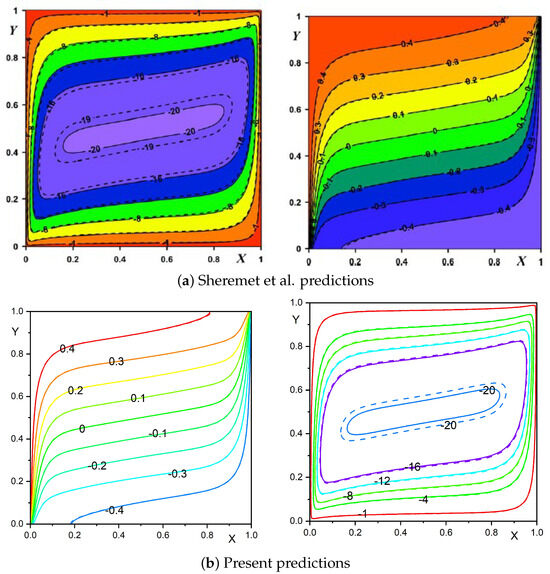
Figure 2.
Benchmarking present predictions (b) against the established results of Sheremet et al. [20] (a) for , , , , and . Solid lines (aluminum foam) and glass balls (dashed lines) as porous structures.
Table 4.
Comparison of average Nusselt number values with literature findings for , , and .
4. Results and Discussion
Here, we present the comprehensive illustrations of buoyancy-assisted convection in an NF-saturated porous structure within an inclined parallelogrammic geometry subjected to discrete thermal boundary conditions. The thermal–hydraulic characteristics of the setup are systematically investigated through computational simulations by resolving the coupled momentum and energy transport equations. Flow patterns and thermal distributions are visualized via streamline and isotherm contours, while heat transfer performance is quantified through estimating the average Nusselt number at the discrete thermal source. The computational domain consists of an oriented parallelogrammic space with localized heating and cooling elements positioned on opposing tilted sidewalls. The simulations were performed with fixed structural parameters (aspect ratio and porosity ) while systematically varying the following thermophysical and geometric parameters:
- Rayleigh number ():
- Source length (): and
- Source position (L): , and
- Enclosure inclination angle ():
- Sidewall inclination angle ():
- Nanoparticle volume fraction ():
4.1. Enclosure Orientation Impact on Hydrodynamic Flow and Thermal Transport
Figure 3 depicts the influence of the geometry inclination angle () on the flow structure and thermal pattern inside the parallelogrammic geometry with a discrete thermal source–sink. The predictions were obtained with fixed parameters of , , , , and . The streamline structure reveals a progressive enhancement in flow circulation intensity with a change in geometry tilting angle. At (Figure 3a), a relatively weak clockwise convective motion is observed with an extreme flow circulation rate of approximately . The hydrodynamic flow exhibits a primary circulation cell with secondary vortices near the geometric corners due to collective influences of discrete thermal conditions and geometrical inclination. When the enclosure is horizontal (, Figure 3b), the circulation intensity increases moderately, with the stream function value reaching and a more organized flow structure concentrated toward the central region. The most profound flow enhancement occurs at (Figure 3c), where the maximum stream function value elevated to approximately , indicating an approximate fold increase in circulation strength compared to the configuration. The isotherm distributions exhibit the corresponding changes in thermal characteristics across three different inclination angles. For , the isotherms are marginally distorted and spread throughout the geometry, indicating thermal boundary layer formation and predominantly a conduction-dominated transport. At , the isotherms exhibit a moderate shift toward the central region, indicating the enhanced convective transport. For the configuration, the thermal contours cluster near the thermal source with reduced thermal boundary layer thickness near both the source and sink. Further, a more pronounced horizontal stratification can be observed in the core region, indicating superior convective mixing and thermal transport efficiency.
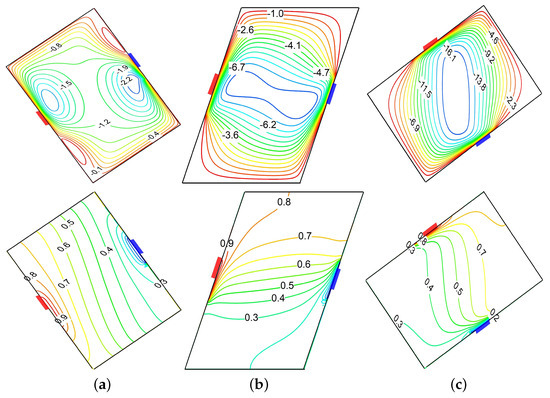
Figure 3.
Effect of geometry inclination on streamlines (top row) and isotherms (bottom row) for , , . (a) . (b) . (c) .
A comprehensive analysis of the global transport rate () sensitivity to variations in and the geometry inclination angle () is presented in Figure 4 with fixed parameters , , and . The graph demonstrates a vivid correlation between the improvement in thermal dissipation and the increasing magnitudes of both and . For all magnitudes of , the global exhibits a monotonic increase as the tilt angle transitions from negative () to positive () inclinations, with a pronounced enhancement observed in the range of . At , increases approximately six-fold from to , whereas at , the enhancement is very modest. An examination of thermal energy dissipation characteristics comparing pure water (H2O) as the reference medium (depicted by solid curves) against NFs with volume concentration (represented by dotted curves) demonstrates that NFs continuously exhibit a reduced performance relative to H2O for all parameter settings. Specifically, at , the NF demonstrates an reduction in mean Nusselt number for . Similarly, at and , the NF manifests a and decline in heat dissipation rate, respectively. This paradoxical deterioration suggests that, despite the enhanced thermal conductivity of NFs, the accompanying viscosity enhancement hinders the formation of stronger convection cells, particularly in the buoyancy-driven flow regime at higher values, an anomalous behavior predicted in the earlier literature [10,20] for a similar model.
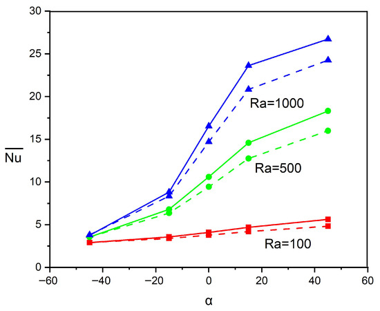
Figure 4.
Inspection of dependency on variations in and for , . Continuous curves correspond to H2O and dashed curves represent NF ().
Figure 5 presents a critical evaluation of the variation in the combined impacts of sidewall tilting () as well as cavity inclination () with fixed parameters , , , and . The observation reveals the complex interactions between these two geometric parameters that profoundly influence thermal dissipation performance. For all three orientations of , the magnitude of remains comparatively low (≈3–4) at , indicating minimal dependence on sidewall tilting at negative geometry inclinations where buoyancy effects are substantially suppressed. As increases toward positive values, thermal transport enhancement becomes pronounced and geometrically dependent, with all configurations exhibiting an increase in . The square domain () demonstrates superior performance, achieving the highest value (≈24.5) at and reaching a constant value. Notably, the negatively tilted parallelogram () exhibits non-monotonic behavior, while the positively tilted configuration () demonstrates continuous enhancement, achieving the maximum heat transfer rate at .
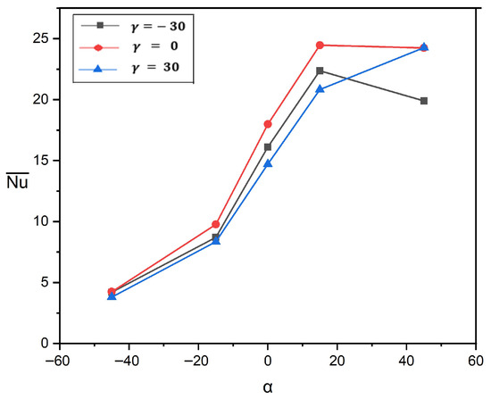
Figure 5.
Inspection of dependency on combined influences of and for , , .
4.2. Thermal Source–Sink Position and Dimension Impact on Hydrodynamic Flow and Thermal Transport
Figure 6 illustrates the positional (L) influence of the thermal source–sink on velocity and temperature distributions for a smaller dimension (). The top row displays streamline contours while the bottom row represents the corresponding isotherms by considering three source positions: , , and . The streamline pattern reveals a complex bi-cellular flow structure at , with counter-rotating vortices of unequal strength, where the primary vortex () dominates the upper region and a secondary vortex () appears near the bottom sink. As the source–sink shifts to a central position (), the flow reorganizes into a more symmetric bi-cellular pattern with two distinct counter-rotating cells of comparable intensity ( for both), positioned diagonally across the enclosure and located near the source and sink. Further shifting the source to , the flow transforms into a distinctly asymmetric pattern characterized by a smaller eddy () in the upper region and a larger, more intense, dominating eddy () at the lower portion. The corresponding isotherms demonstrate a progressive transformation from steep, concentrated gradients near the source and sink regions at to more uniformly distributed thermal fields at . In particular, at the lower positioning of source (), the isotherms exhibit significant clustering near the bottom left and top right regions, indicating intense local heat transport. As L increases to and subsequently to , the thermal stratification becomes more balanced throughout the geometry, with progressively more uniform gradients between the source and the sink-placed boundaries. Figure 7 elucidates the significant influence of thermal source–sink location on velocity and temperature distributions for an extended thermal source–sink length of . Unlike the previous case with a shorter source–sink length (), this configuration with an extended source–sink length generates the strong single-eddy flow patterns across all source positions, albeit with significant variations in intensity and structure. At , the streamline distribution exhibits a strong uni-cellular structure with a maximum intensity of concentrated in the lower portion. As the source position moves further ( and ), the circulation core shifts toward the middle and upper regions with a slightly increased intensity ( and ) while maintaining similar structural characteristics. The corresponding isotherms demonstrate parallel evolutionary behavior, transitioning from a moderately stratified thermal field at to increasingly distorted patterns at higher source positions. This progression vividly demonstrates that, with an extended thermal source length (), the source–sink position exerts a profound influence on flow morphology and thermal transport characteristics.
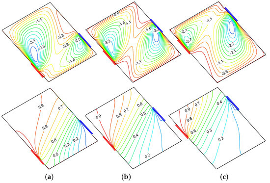
Figure 6.
Influence of source–sink arrangement on streamlines (top row) and isotherms (bottom row) for , , . (a) . (b) . (c) .
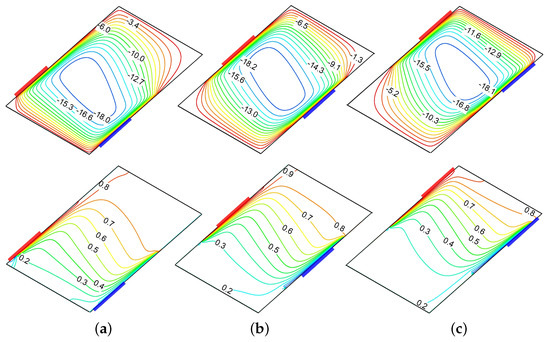
Figure 7.
Influence of source–sink arrangement on streamlines (top row) and isotherms (bottom row) for , , , . (a) . (b) . (c) .
Figure 8 depicts the evolution of for different magnitudes of and thermal source–sink locations with , , and . The estimation presents a comparative analysis of between H2O (dashed lines) and NF with (solid lines). For all magnitudes of Rayleigh numbers (), the global Nu reveals a declining trend as the source–sink position shifts upward from to , indicating that lower source–sink placements promote a more efficient heat dissipation rate. This trend is most pronounced at lower Rayleigh numbers, where the thermal efficiency decreases by approximately 54% for to 28% for as L increases from to . With regard to the inclusion of NPs, the base fluid (H2O) consistently outperforms NF across all conditions. This enhancement is particularly significant for the middle position (), where the improvement reaches approximately 9.8%, 11.8%, and 9.1% for , , and respectively, compared to the lower enhancement percentages observed at . The superior performance at lower source–sink positions can be attributed to the favorable alignment of the buoyancy-driven convection patterns with the thermal gradient when the heat source is positioned near the bottom of the inclined wall. The outcomes in Figure 9 illustrate the sensitivity of the thermal transfer rate performance to variations in the thermal source–sink dimension () across different Rayleigh numbers. Analysis of the prediction reveals that the consistently decreases as the thermal source length () increases from 0.2 to 1.0 in all Rayleigh numbers, indicating that a shorter thermal source–sink efficiently promotes higher heat dissipation. Quantitatively, the heat dissipation efficiency decreases by approximately 33% for , 35% for , and 20% for as increases from 0.2 to 1.0. The comparative performance between NFs and water reveals that H2O (base fluid) consistently outperforms NFs at all source lengths, with enhancement ranging from 10 to 17%.
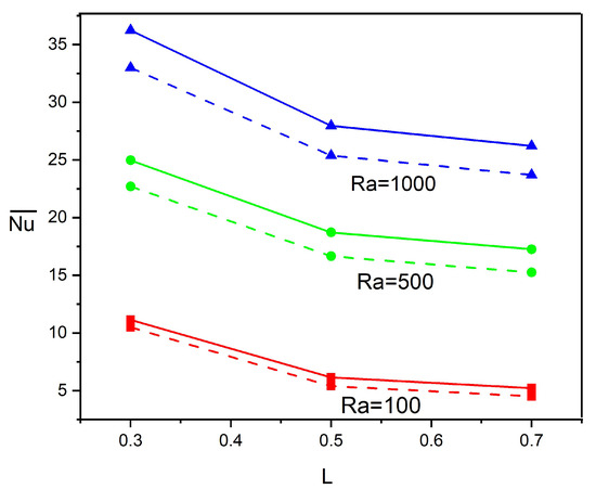
Figure 8.
Heat dissipation rate variations with thermal source locations and at , , . Continuous curves correspond to H2O and dashed curves represent NF ().
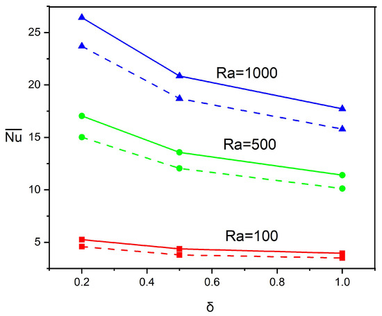
Figure 9.
Inspection of dependency on variations in and for , , . Continuous curves correspond to H2O and dashed curves represent NF ().
4.3. Influence of and on Hydrodynamic Motion and Heat Transport
Figure 10 portrays the influence of sidewall orientation () on flow and thermal patterns at , with parameters , , , and fixed. The upper row displays streamlines while the bottom row represents isotherms for three distinct configurations: , , and . The streamline structure reveals a strong clockwise rotating cell that dominates the flow field in all three geometries, driven by the thermal buoyancy forces between the source (red segment on left wall) and sink (blue segment on right wall). The circulation intensity is considerably influenced by the sidewall orientation, with maximum stream function values of approximately for , for , and for . This progressive augmentation elucidates that the positive sidewall tilt () elevates convective circulation by approximately 20% compared to the negative tilt configuration. The corresponding isotherms demonstrate substantial deformation from the conduction-dominated pattern, confirming the prevalence of convective heat transfer. As increases from to , the isotherms exhibit increased clustering near the source and sink regions, particularly evident in the case, where temperature gradients are most pronounced. These observations collectively demonstrate that the parallelogrammic configuration with a positive sidewall orientation () provides the optimal thermal performance among the three orientations investigated due to its favorable alignment with the buoyancy-driven flow dynamics.
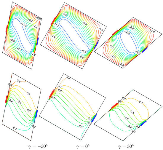
Figure 10.
Sidewall tilt angle impact on streamlines (top row) and isotherms (bottom row) for , , .
Figure 11 demonstrates the impact of sidewall orientation () on thermal efficiency for diverse magnitudes of in the tilted parallelogrammic geometry with fixed parameters , , and . The overall thermal dissipation rate () exhibits a non-monotonic variation with across all examined Rayleigh numbers. As varies across , heat dissipation efficiency declines, with the reduction more pronounced at positive tilt angles. For , the thermal dissipation rate reaches its maximum at , with the base-fluid () achieving compared to the NF () , indicating an approximately 7.7% enhancement. For , similar behavior is predicted with peak values occurring near , where H2O demonstrates an approximately 11.4% improvement over NFs ( versus ). For the lower considered in this analysis, the predictions exhibit less sensitivity to variations, with maximum values slightly shifted toward and the base fluid maintaining an approximately 13.3% enhancement across the examined tilt range. Notably, the thermal performance declines at extreme tilt angles (), and it appears to be more significant as the magnitude of increases, suggesting that an optimal configuration becomes more critical at higher convection intensities.
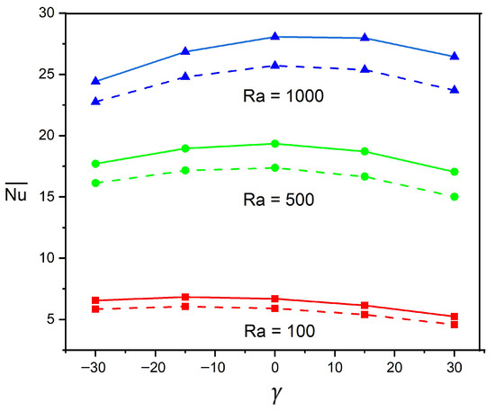
Figure 11.
Heat dissipation rate variations with Rayleigh number and at , . Continuous curves correspond to H2O and dashed curves represent NF ().
4.4. Impact of and on Hydrodynamic Flow and Thermal Transport
Figure 12 displays the profound physical transformations in terms of NF buoyant flow and thermal distributions with Rayleigh number variation for H2O as well as NF. At , a weak single-eddy circulation exists with , indicating that buoyancy forces marginally exceeding viscous resistance and thermal distribution contours exhibit a near-conduction regime characterized by almost upright equally spaced isotherms. The fundamental transition in heat transport processes occurs at , where the convective motion begins to dominate, accompanied by the intensive streamline, which increases more than five-fold (). This is further evidenced by significant isotherm distortion as the buoyant fluid motion proactively transports thermal energy across the geometry. The convection-dominant phenomenon is further amplified at , where the circulation rate intensifies substantially () with a pronounced change in the vortex direction, while isotherms develop distinctive thermal boundary layers near active walls. The physical emphasis of these transformations could be interpreted as the progressive shift from molecular-level heat transport to bulk fluid transport as the driving mechanism. In addition, the substantial thinning of the thermal boundary layer has been predicted at , where sharp thermal gradients form adjacent to the thermal source and sink, which dramatically elevates the local thermal transport rates.
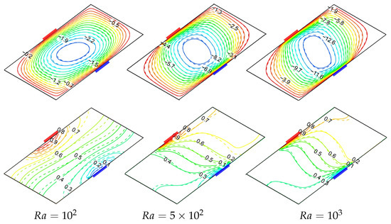
Figure 12.
Streamlines (top row) and isotherms (bottom row) for diverse magnitudes of at , , . Continuous curves correspond to H2O and dashed curves represent NF ().
Figure 13 elucidates the thermophysical mechanisms governing heat dissipation in a discretely heated–cooled tilted parallelogrammic geometry as functions of NP concentration () and Rayleigh number () at fixed geometric parameters (, , ). A counterintuitive thermal phenomenon has been noticed where enhancing NP concentration consistently reduces heat transport efficiency at all examined values, contradicting the conventional comprehension that elevated thermal conductivity from NPs improves the thermal transport. This contradictory prediction reveals the dominance of viscosity effects over conductivity enhancement in deaccelerating the buoyant-assisted motion, and a similar prediction was made in previous investigations [10,20]. The elevated viscosity from the addition of NP suppresses flow mobility and consequently reduces the convective transport mechanisms. Further, the thermal source–sink dimension () induces a substantial impact on heat dissipation dynamics, with the smaller heat source–sink () consistently evidencing superior thermal efficiency compared to the larger source–sink () across all parametric combinations. This enhancement in can be attributed to concentrated thermal gradients generated by the smaller source, which in turn amplify the local buoyancy-driven flows and develop stronger convection currents. In accordance with established predictions, the exhibits the most pronounced impact on the thermal dissipation mechanism, with increasing approximately five-fold from to for pure fluid (), characterizing the significant progression from a conduction-dominated thermal regime to a convection-prevalent thermal state. In particular, the negative slope of versus steepens with an increase in , demonstrating that the suppression effect of NPs becomes more detrimental at higher magnitudes of where buoyant convection would otherwise be more vigorous.
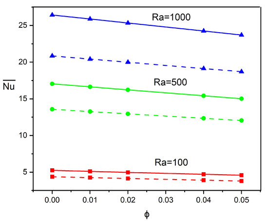
Figure 13.
Heat dissipation rate variations with collective influences of and at , , . Dashed curves correspond to and continuous curves represent smaller source dimension .
5. Conclusions
A comprehensive numerical investigation has been conducted to elucidate the characteristics of buoyancy-driven convective phenomena and associated thermal transport mechanisms within an NF-saturated porous parallelogrammic geometry. The geometry also incorporates strategically positioned discrete thermal source and sink elements, presenting a configuration with significant practical relevance. The systematic parametric analysis encompassing diverse physical and geometrical parameters has yielded quantifiable insights into the governing flow and transport phenomena. The salient observations and important conclusions derived from this investigation are enumerated as follows:
- 1.
- Thermal source–sink positioning predominantly influences the convective flow patterns and thermal performance, with intermediate positions () generating the most energetic flow structures, while extreme locations () promote more uniform thermal distributions.
- 2.
- The complex interaction between sidewall orientation () and enclosure tilting () reveals a significant influence on thermal transport behavior. The optimal geometric configuration transitions from at moderate cavity inclinations to at high positive inclinations (), suggesting that alignment between the buoyancy-driven flow direction and the enclosure geometry becomes increasingly critical as approaches . These findings demonstrate that strategic manipulation of and can produce substantial thermal performance improvements.
- 3.
- Source–sink configuration optimization shows that positioning thermal elements closer to the bottom wall () and using smaller dimensions () substantially enhance thermal efficiency, with improvements of approximately 38% and 45%, respectively, at higher Rayleigh numbers.
- 4.
- Nanofluid thermal transport consistently exhibits a reduction compared to the base fluid across all examined parameters, with the most pronounced degradation occurring at higher magnitudes of and moderate inclination angles, mainly attributed to competing impacts among the thermal conductivity enhancement and viscosity-induced circulation dampening.
- 5.
- Sidewall orientation () sensitivity demonstrates optimal performance at near-rectangular configurations ( to ), with a 7–12% heat transfer decline toward extreme inclinations, intensifying at higher Rayleigh numbers, with showing the most pronounced variation.
- 6.
- Optimal thermal performance is achieved through strategic combinations of higher Rayleigh numbers, appropriate source-s-ink arrangements, positive enclosure tilting, and favorable geometric inclinations that enhance the buoyancy-driven convection.
- 7.
- The current predictions provide fundamental insights for optimizing thermal management systems in porous media applications and highlight the complex interplay among geometric parameters, fluid properties, and thermal transport mechanisms in an inclined parallelogrammic geometry.
- 8.
- It is worth mentioning that the present study is conducted within the framework of the Darcy model, which limits the investigation to Rayleigh numbers below . The range of Rayleigh numbers (–) represents the complete validity domain of the Darcy approximation, where viscous forces dominate and inertial effects remain negligible. While higher magnitudes of are indeed encountered in many practical applications, their investigation would necessitate the adoption of non-Darcy models. Future studies should extend this analysis to the non-Darcy regime using appropriate porous media formulations to capture the behavior at higher values.
Author Contributions
Conceptualization and original draft preparation, M.S.; review and editing, S.A.A.; project administration, methodology, and software, V.C.V.; preparation of graphs and literature review, V.S.; plagiarism reduction and validation, A.A.M. All authors have read and agreed to the published version of the manuscript.
Funding
This work is supported by the University of Technology and Applied Sciences(UTAS)-Ibri, Oman, under the Internal Research Funding project No. IRG-IBRI-25-49 and Spanish Government under grants PID2023-150014OB-C21 and PID2023-150029NB-I00.
Data Availability Statement
The raw data supporting the conclusions of this article will be made available by the authors on request.
Acknowledgments
The authors, V.C.V. and V.S., express their gratitude to JSSATE, Bangalore, VTU, Belagavi and FET, Jain Deemed-to-be University, Ramanagaram, India. M.S. acknowledges the support and encouragement by the University of Technology and Applied Sciences, Ibri, Oman.
Conflicts of Interest
The authors declare no conflicts of interest.
Nomenclature
The following abbreviations are used in this manuscript:
| A | aspect ratio |
| g | gravitational acceleration |
| H | height of the enclosure |
| L | width of the enclosure |
| k | thermal conductivity |
| K | permeability constant |
| local Nusselt number | |
| average Nusselt number | |
| p | pressure |
| Rayleigh number | |
| t | dimensional time |
| T | temperature |
| sink temperature | |
| source temperature | |
| velocity components in the x and y direction | |
| Cartesian coordinates | |
| transformed coordinates | |
| L | source position |
| heat capacity | |
| Greek Letters | |
| Cavity inclination | |
| source length | |
| sidewall inclination angle | |
| dynamic viscosity | |
| nanoparticle volume fraction | |
| fluid density | |
| heat capacity ratio | |
| dimensionless transformed coordinates | |
| dimensionless time | |
| dimensional temperature | |
| stream function | |
| dimensionless stream function | |
| thermal expansion coefficient (1/K) | |
| temperature difference K | |
| porosity | |
| Subscripts | |
| f | base fluid |
| nanofluid | |
| p | nanoparticle |
| m | porous structure |
| nanofluid porous structure | |
| Abbreviations | |
| alternating direction implicit | |
| successive line over-relaxation | |
| nanofluid | |
| nanoparticle | |
References
- Nield, D.A.; Bejan, A. Convection in Porous Media, 5th ed.; Springer: Cham, Switzerland, 2017. [Google Scholar]
- Vafai, K. Handbook of Porous Media, 3rd ed.; CRC Press: Boca Raton, FL, USA, 2015. [Google Scholar]
- Seki, N.; Fukusako, S.; Yamaguchi, A. An Experimental Study of Free Corrective Heat Transfer in a Parallelogrammic Enclosure. ASME J. Heat Mass Transf. 1983, 105, 433–439. [Google Scholar] [CrossRef]
- Hyun, J.M.; Choi, B.S. Transient Natural Convection in a Parallelogram-Shaped Enclosure. Int. J. Heat Fluid Flow 1990, 11, 129–134. [Google Scholar] [CrossRef]
- Baïri, A.; De María, J.M.G.; Laraqi, N. Transient Natural Convection in Parallelogrammic Enclosures with Isothermal Hot Wall. Experimental and Numerical Study Applied to on-Board Electronics. Appl. Therm. Eng. 2010, 30, 1115–1125. [Google Scholar] [CrossRef]
- Baïri, A.; De María, J.M.G. Nu–Ra–Fo Correlations for Transient Free Convection in 2D Convective Diode Cavities with Discrete Heat Sources. Int. J. Heat Mass Transf. 2012, 57, 623–628. [Google Scholar] [CrossRef]
- Gupta, N.; Nayak, A.K. Performance Evaluation of Coolant Air with Buoyancy in a Parallelogrammic Mixed Displacement Ventilated System. Int. J. Mech. Sci. 2018, 149, 38–53. [Google Scholar] [CrossRef]
- Ravindra, P.; Sankar, M.; Rasappan, S.; Majrafi, W.A.A.; Rajan, P.; Kumar, S.S. Double-Diffusive Magnetoconvection in a Tilted Porous Parallelogrammic Domain with Discrete Heated-Cooled Segments: Leveraging Machine Learning and CFD Approach. Results Eng. 2025, 27, 105921. [Google Scholar] [CrossRef]
- Choi, U.S. Enhancing Thermal Conductivity of Fluids with Nanoparticles. In Proceedings of the ASME 1995 International Mechanical Engineering Congress and Exposition, San Francisco, CA, USA, 12–17 November 1995; Volume 66, pp. 99–105. [Google Scholar] [CrossRef]
- Ghalambaz, M.; Sheremet, M.A.; Pop, I. Free Convection in a Parallelogrammic Porous Cavity Filled with a Nanofluid Using Tiwari and Das’ Nanofluid Model. PLoS ONE 2015, 10, e0126486. [Google Scholar] [CrossRef]
- Tiwari, R.K.; Das, M.K. Heat transfer augmentation in a two-sided lid-driven differentially heated square cavity utilizing nanofluids. Int. J. Heat Mass Transf. 2007, 50, 2002–2018. [Google Scholar] [CrossRef]
- Alsabery, A.I.; Saleh, H.; Hashim, I.; Siddheshwar, P.G. Transient Natural Convection Heat Transfer in Nanoliquid-Saturated Porous Oblique Cavity Using Thermal Non-Equilibrium Model. Int. J. Mech. Sci. 2016, 114, 233–245. [Google Scholar] [CrossRef]
- Hussein, A.K.; Mustafa, A.W. Natural Convection in Fully Open Parallelogrammic Cavity Filled with Cu–Water Nanofluid and Heated Locally from Its Bottom Wall. Therm. Sci. Eng. Prog. 2017, 1, 66–77. [Google Scholar] [CrossRef]
- Nayak, R.K.; Bhattacharyya, S.; Pop, I. Effects of Nanoparticles Dispersion on the Mixed Convection of a Nanofluid in a Skewed Enclosure. Int. J. Heat Mass Transf. 2018, 125, 908–919. [Google Scholar] [CrossRef]
- Bhuiyan, A.H.; Munshi, M.J.H.; Alim, M.A.; Alam, M.S. MHD Effect on Mixed Convection Heat Transfer of Cu-Water Nanofluid in a Vented Parallelogrammic Cavity with Injection or Suction. AIP Conf. Proc. 2019, 2121, 070008. [Google Scholar] [CrossRef]
- Yasin, A.; Ullah, N.; Nadeem, S.; Ghazwani, H.A. Numerical Simulation for Mixed Convection in a Parallelogram Enclosure: Magnetohydrodynamic (MHD) and Moving Wall-Undulation Effects. Int. Commun. Heat Mass Transf. 2022, 135, 106066. [Google Scholar] [CrossRef]
- Shahid, H.; Sajida, M.; Khan, W.A.; Ahmad, F. Analysis of Heat Transfer in a Parallelogram-Shaped Cavity with Porous Medium under Non-Uniform Temperature. Alex. Eng. J. 2024, 95, 204–223. [Google Scholar] [CrossRef]
- Oztop, H.F.; Abu-Nada, E. Numerical study of natural convection in partially heated rectangular enclosures filled with nanofluids. Int. J. Heat Fluid Flow 2008, 29, 1326–1336. [Google Scholar] [CrossRef]
- Groşan, T.; Revnic, C.; Pop, I.; Ingham, D.B. Free Convection Heat Transfer in a Square Cavity Filled with a Porous Medium Saturated by a Nanofluid. Int. J. Heat Mass Transf. 2015, 87, 36–41. [Google Scholar] [CrossRef]
- Sheremet, M.A.; Grosan, T.; Pop, I. Free Convection in a Square Cavity Filled with a Porous Medium Saturated by Nanofluid Using Tiwari and Das’ Nanofluid Model. Transp. Porous Media 2015, 106, 595–610. [Google Scholar] [CrossRef]
- Alsabery, A.I.; Chamkha, A.J.; Saleh, H.; Hashim, I. Natural Convection Flow of a Nanofluid in an Inclined Square Enclosure Partially Filled with a Porous Medium. Sci. Rep. 2017, 7, 2357. [Google Scholar] [CrossRef]
- Alsabery, A.I.; Chamkha, A.J.; Saleh, H.; Hashim, I.; Chanane, B. Effects of Finite Wall Thickness and Sinusoidal Heating on Convection in Nanofluid-Saturated Local Thermal Non-Equilibrium Porous Cavity. Phys. A Stat. Mech. Its Appl. 2017, 470, 20–38. [Google Scholar] [CrossRef]
- Sankar, M.; Swamy, H.A.K.; Do, Y.; Altmeyer, S. Thermal Effects of Nonuniform Heating in a Nanofluid-filled Annulus: Buoyant Transport versus Entropy Generation. Heat Transf. 2021, 51, 1062–1091. [Google Scholar] [CrossRef]
- Chamkha, A.J.; Selimefendigil, F. MHD Free Convection and Entropy Generation in a Corrugated Cavity Filled with a Porous Medium Saturated with Nanofluids. Entropy 2018, 20, 846. [Google Scholar] [CrossRef] [PubMed]
- Alhashash, A. Natural Convection of Nanoliquid from a Cylinder in Square Porous Enclosure Using Buongiorno’s Two-Phase Model. Sci. Rep. 2020, 10, 143. [Google Scholar] [CrossRef] [PubMed]
- Abed, W.M.; Al-Damook, A. Optimal Characteristics of Natural Convection in a Square Porous-Nanofluid-Filled Enclosure Containing Three Tubes. Numer. Heat Transf. Part A Appl. 2023, 85, 1706–1729. [Google Scholar] [CrossRef]
- Azad, A.K.; Hasan, M.J.; Karim, M.F.; Alam, E.M.M.; Rahman, M.M. Rotational Effect of a Cylinder on Hydro-Thermal Characteristics in a Partially Heated Square Enclosure Using CNT-Water Nanofluid. Heliyon 2023, 9, e22744. [Google Scholar] [CrossRef]
- Bondareva, N.S.; Sheremet, M.A. Numerical Simulation of Heat Transfer Performance in an Enclosure Filled with a Metal Foam and Nano-Enhanced Phase Change Material. Energy 2024, 296, 131123. [Google Scholar] [CrossRef]
- Lakshmi, C.V.; Sireesha, M.; Venkatadri, K.; Fazuruddin, S.; Arigela, S. Natural convection of nanofluid flow in a porous enclosure with isothermal heated plate: A Tiwari and Das nanofluid model. Int. J. Thermofluids 2025, 27, 101238. [Google Scholar] [CrossRef]
- Al-Kaby, R.N.; Abdulhaleem, S.M.; Hameed, R.H.; Yasiry, A. Mixed Convection Heat Transfer and Fluid Flow of Nanofluid/Porous Medium under Magnetic Field Influence. Appl. Sci. 2025, 15, 1087. [Google Scholar] [CrossRef]
- Vigneshwari, S.; Reddappa, B.; Sumithra, A.; Kumar, B.R.; Öztop, H.F. Thermal and Flow Dynamics of Unsteady MHD Nanofluid Convection in a Partially Heated Porous Cavity. J. Therm. Anal. Calorim. 2025, 150, 5601–5616. [Google Scholar] [CrossRef]
- Younis, O.; Alizadeh, M.; Hussein, A.K.; Ali, B.; Biswal, U.; Malekshah, E.H. MHD Natural Convection and Radiation over a Flame in a Partially Heated Semicircular Cavity Filled with a Nanofluid. Mathematics 2022, 10, 1347. [Google Scholar] [CrossRef]
- Kim, H.; Thirumalaisamy, K.; Venkatadri, K. Computational Analysis of Magnetohydrodynamic Buoyancy-Driven Flow and Thermal Transmission within a Circular Dome-Shaped Porous Enclosure Using Finite Difference Scheme. Int. J. Numer. Methods Heat Fluid Flow 2025, 35, 1642–1679. [Google Scholar] [CrossRef]
- Ali, A.; Ayaz, M.; Ahmad, Z.; Marei, A.M. Analysis of Entropy Generation in Magnetohydrodynamic Convective Flow of Nanofluids within a Wavy Trapezoidal Enclosure: A Brinkmann-Forchheimer Model Using Finite Element Method. Case Stud. Therm. Eng. 2025, 73, 106719. [Google Scholar] [CrossRef]
- Izadi, S.; Armaghani, T.; Ghasemiasl, R.; Chamkha, A.J.; Molana, M. A Comprehensive Review on Mixed Convection of Nanofluids in Various Shapes of Enclosures. Powder Technol. 2019, 343, 880–907. [Google Scholar] [CrossRef]
- Abdulkadhim, A.; Abed, I.M.; Said, N.M. An Exhaustive Review on Natural Convection within Complex Enclosures: Influence of Various Parameters. Chin. J. Phys. 2021, 74, 365–388. [Google Scholar] [CrossRef]
- Sivanandam, S.; Cheong, H.T.; Thangaraj, A. Numerical Study on Free Convection in an Inclined Wavy Porous Cavity with Localized Heating. Modelling 2025, 6, 30. [Google Scholar] [CrossRef]
- Qureshi, H.; Rani, S.; Altmeyer, S. Investigation of Marangoni Convective Flow of Hybrid Nanofluids In Darcy-Forchheimer Porous Medium. J. Appl. Mater. Sci. Eng. Res. 2024, 8, 1–14. [Google Scholar] [CrossRef]
- Ahlawat, A.; Sharma, M.K.; Ghachem, K.; Alshammari, B.M.; Kolsi, L. Impacts of Sinusoidal Heat Flux and Embraced Heated Rectangular Cavity on Natural Convection within a Square Enclosure Partially Filled with Porous Medium and Casson-Hybrid Nanofluid. Open Phys. 2025, 23, 20250142. [Google Scholar] [CrossRef]
- Marfouk, A.; Mansour, A.; Hasnaoui, A.; Amahmid, A.; Hasnaoui, M. MHD Free Convection in an Enclosure Loaded with Nanofluid and Partially Cross-Heated. J. Appl. Fluid Mech. 2025, 18, 1720–1734. [Google Scholar] [CrossRef]
- Sayyou, H.; Belabid, J.; Öztop, H.F.; Allali, K. Vibrational effects on thermosolutal free convection of Cu-Al2O3/water nanofluids in a partially heated and salted square porous enclosure. J. Mol. Liq. 2025, 423, 126990. [Google Scholar] [CrossRef]
- Baytas, A.C.; Pop, I. Free Convection in Oblique Enclosures Filled with a Porous Medium. Int. J. Heat Mass Transf. 1999, 42, 1047–1057. [Google Scholar] [CrossRef]
- Jagadeesha, R.D.; Prasanna, B.M.R.; Sankar, M. Numerical Simulation of Double Diffusive Magnetoconvection in an Inclined Parallelogrammic Porous Enclosure with an Internal Heat Source. Mater. Today Proc. 2017, 4, 10544–10548. [Google Scholar] [CrossRef]
- Saeid, N.H.; Pop, I. Transient free convection in a square cavity filled with a porous medium. Int. J. Heat Mass Transf. 2004, 47, 1917–1924. [Google Scholar] [CrossRef]


Disclaimer/Publisher’s Note: The statements, opinions and data contained in all publications are solely those of the individual author(s) and contributor(s) and not of MDPI and/or the editor(s). MDPI and/or the editor(s) disclaim responsibility for any injury to people or property resulting from any ideas, methods, instructions or products referred to in the content. |
© 2025 by the authors. Licensee MDPI, Basel, Switzerland. This article is an open access article distributed under the terms and conditions of the Creative Commons Attribution (CC BY) license (https://creativecommons.org/licenses/by/4.0/).