Article

Accurate Implementation of Rotating Magneto-Hydrodynamics in a Channel Geometry Using an Influence Matrix Method

by
Jean-Clément Ringenbach
1,*,
Steven M. Tobias
2,* and
Tobias M. Schneider
1,*
1
Emergent Complexity in Physical Systems, École Polytechnique Fédérale de Lausanne, 1015 Lausanne, Switzerland
2
School of Physics & Astronomy, University of Edinburgh, James Clerk Maxwell Building, Edinburgh EH9 3FD, UK
*
Authors to whom correspondence should be addressed.
Mathematics 2025, 13(16), 2549; https://doi.org/10.3390/math13162549
Submission received: 31 March 2025 / Revised: 24 June 2025 / Accepted: 3 July 2025 / Published: 8 August 2025
(This article belongs to the Special Issue Numerical Simulation and Methods in Computational Fluid Dynamics)

Abstract

We numerically study wall-bounded convectively driven magneto-hydrodynamic (MHD) flows subject to rotation in a Cartesian periodic channel. For the accurate treatment of the rotating MHD equations, we develop a pseudo-spectral simulation code with accurate treatment of boundary conditions for both velocity and magnetic fields. The solenoidal condition on the magnetic field is enforced by the addition of a fictitious magnetic pressure. This allows us to employ an influence matrix method with tau correction for the treatment of velocity and magnetic fields subject to Robin boundary conditions at the confining walls. We validate the developed method for the specific case of no slip velocity and perfectly conducting magnetic boundary conditions. The validation includes the accurate reproduction of linear stability thresholds and of turbulent statistics. The code shows favorable parallel scaling properties.
MSC:
76W05; 76M22

1. Introduction

Many phenomena in geophysical and astrophysical contexts involve the interaction of turbulent, conducting fluid flows with magnetic fields. A prime example is the magnetic fields of stars and planetary objects, where convectively driven flows of conducting fluids, subject to the rotation of their astrophysical bodies, are believed to generate self-sustained dynamos. This is the case for stars [1], rocky planets [2], gas giants and moons [3].
Such phenomena including self-sustained dynamos often occur in the highly nonlinear turbulent regime; therefore, characterizing and describing the physical mechanism in this regime is aided by augmenting linear and weakly nonlinear approaches with a fully nonlinear description. A fully nonlinear description, in this context, may refer either to an accurate direct numerical simulation or the identification and tracking of non-chaotic so-called invariant solutions, including equilibria and periodic orbits. The latter approach, in the context of a dynamical systems description of the flow, carries the promise that tracking invariant solutions in parameter space can provide insights into the parameter dependence of various phenomena [4]. This has been notably accomplished in turbulent, non-magnetic shear flows [5,6], and some invariant solutions have also been found in spherical shell dynamo solutions [7,8].
While studying convection in an astrophysical context suggests the consideration of spherical shell domains, many important phenomena only involve scales that are small compared with the radius of curvature of such a shell, so that they can also be studied in rotating plane layer models within the f-plane approximation. In particular, the increase in heat transport due to dynamo effect, which is often discussed in relation to a possible explanation for the existence of self-sustained dynamos in rapidly rotating systems, is also observed within Cartesian domains [9,10].
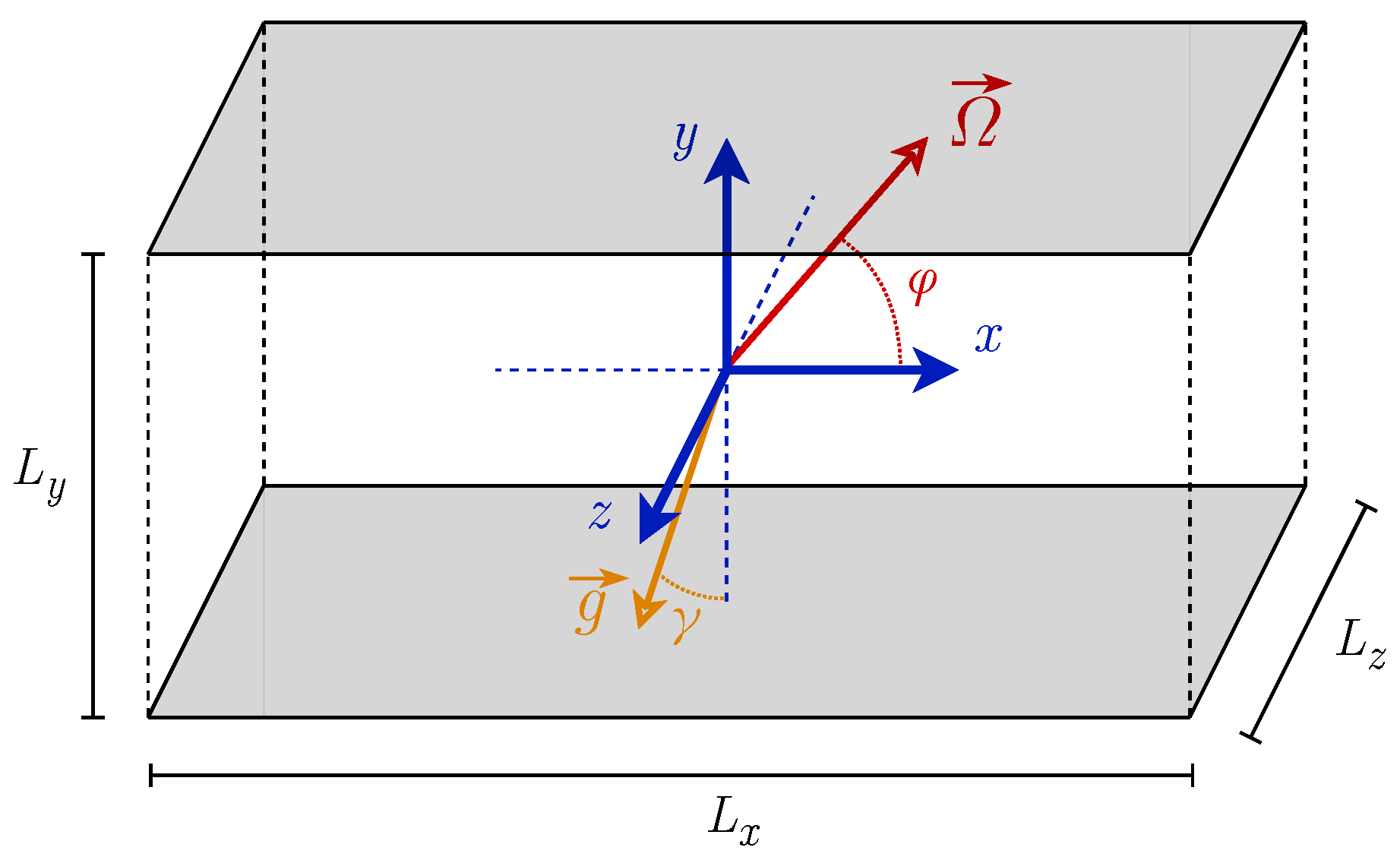
We, consequently, also consider the well-established model of a doubly periodic box of a conducting convective fluid layer at a prescribed latitude, as illustrated in Figure 1, representing a slab of a convective region where curvature effects are neglected. The flow is convectively driven, subject to rotation and potentially imposed external magnetic fields. The imposed fields may represent the large-scale fields surrounding the portion of the astrophysical object considered—such as a stellar convection zone or convective planetary interiors.
The discussed flow problem has been extensively studied using linear stability analysis [11], investigating the destabilizing and stabilizing effects of rotation and imposed fields on thermally driven convection, and using nonlinear simulations [12,13]. The widely accepted hypothesis is that magnetic fields enhance turbulent convection, leading to stronger field generation until saturation and increased heat transport. This is analogous to the fact that, in the linear regime, the interaction between imposed magnetic fields and rotation can induce instabilities that enable convection, which would not occur in the non-rotating non-magnetic case [14].
To study such flow problems using fully nonlinear approaches, and in order to specifically lay the foundation for a dynamical systems description based on exact invariant solutions, we present a highly accurate numerical solver for the MHD equations. To benefit from the superior approximation properties of a spectral discretization, we consider the geometry of a doubly periodic box, which allows us to study the coupling mechanisms between convectively driving, magnetic fields and rotation that control MHD flows in astrophysical contexts.
Here, we specifically present a high-accuracy pseudo-spectral MHD scheme that precisely handles boundary conditions at confining walls using the influence matrix method [15]. We introduce a fictitious magnetic pressure in the induction equation and apply an extended influence matrix method with Tau correction and Robin boundary conditions to handle both the velocity and magnetic fields, ensuring incompressibility and magnetic solenoidality at machine-precision accuracy. These methods are implemented in a parallel fashion on top of the existing C++ ChannelFlow 2.0 code [16,17]. Our code demonstrates good parallel scaling and is validated against results from the literature. With its accuracy, parallel scaling and straightforward interfacing with Newton-based shooting methods, we expect the code to allow us to efficiently compute and track unstable equilibrium and periodic orbit solutions of the nonlinear MHD equations.

2. Materials and Methods

2.1. Equations and Control Parameters

We consider a channel, periodic in the streamwise (x) and spanwise (z) directions and wall-bounded in the vertical (y) direction.
Specifically, we consider a spatial domain D = [ 0 , L x ) × [ a , b ] × [ 0 , L z ) R 3 depicted in Figure 2. The velocity, magnetic, temperature and pressure fields
U ( x , t ) : D × R + R 3 ,                         B ( x , t ) : D × R + R 3 ,                         T ( x , t ) : D × R + R , P ( x , t ) : D × R + R ,
are governed by the standard magnetohydrodynamics (MHD) equations for a conducting, convectively driven incompressible Newtonian fluid subject to rotation
· U = 0 ,
· B = 0 ,
U t + U · U + Ω e ^ Ω × U = P + λ × B × B + ν 2 U + β + T r e f T e ^ g ,
B t = × U × B + η 2 B ,
T t + U · T = κ 2 T .
Here, we provide the nondimensional formulation, with (1) and (2) indicating constraints enforcing the incompressibility of the fluid, and the absence of magnetic monopoles, also called the solenoidal condition. Equation (3) describes momentum balance incorporating coupling to temperature under the Boussinesq approximation, the Coriolis force and the Lorentz force yielding the coupling to the magnetic field. The induction in Equation (4) captures the diffusion and generation of magnetic fields through charges advected by the fluid flow. It is derived from the Maxwell equations neglecting relativistic terms and assuming Ohm’s law j = σ ( E + U × B ) , where σ is the electrical conductivity [18]. The MHD equations are completed by the temperature advection and diffusion in (5). The parameters Ω , λ , ν , β , η and κ indicate rotation strength, magnetic coupling, momentum diffusivity, hydrostatic pressure, magnetic diffusivity and thermal diffusivity. The unit vectors are
e ^ g ( γ x ) = sin ( γ x ) e ^ x cos ( γ x ) e ^ y , e ^ Ω ( ϕ ) = cos ( ϕ ) e ^ x + sin ( ϕ ) e ^ y ,
with γ x and ϕ indicating the angles in the ( e ^ x , e ^ y ) plane between e ^ y and gravity, and between e ^ x and the rotation vector, as shown in Figure 2. In an astrophysical context, the former accounts for gravity inclination due, for instance, to the ellipsoidity of the body, and the latter represents the latitude at which the system is defined on (see Figure 1).
The governing MHD equations have been rendered nondimensional using the following length, time, temperature, mass and magnetic field scales:
L * =   H 0 * , t * =   H 0 * / U 0 * , T * =   Δ T 0 * , M * =   ρ 0 * H 0 * 3 , B * =   B 0 * ,
where the star * denotes dimensional quantities. The length scale H 0 * is the vertical extent of the domain. For the time scale, we choose common free-fall units with the free-fall velocity U 0 * (see below). We allow the scale for the magnetic field strength to be chosen dependent on the specific MHD problem considered. If an external magnetic field is imposed, this imposed field provides the natural magnetic scale [19,20]. Without an imposed external field, a velocity-based scale such as one based on the Alfvén velocity U 0 * = B 0 * / ρ 0 * μ 0 * is more appropriate [9,21]. This is the difference between dynamo calculations and magnetoconvection calculations.
U 0 * = g * α * Δ T 0 * H 0 * , B 0 * = U 0 * ρ 0 * μ 0 * or B 0 * .
The choice of scales (7)–(8) yields the classical dimensionless numbers
Ra = g * α * Δ T 0 * H 0 * 3 κ * ν * , Ek = ν * Ω * H 0 * 2 , Pr = ν * κ * , Pr m = ν * η * , Q = B 0 * 2 H 0 * 2 ρ 0 * μ 0 * ν * η * ,
with Ra the Rayleigh number, Ek the Ekman number, Pr the Prandtl number, Pr m the magnetic Prandtl number and Q the Chandrasekhar number. The control parameters of the Equations (3)–(5) are expressed in terms of classical dimensionless numbers as
Ω = 2 Ek Pr Ra ,           λ = Q Pr Ra Pr m ,           ν = Pr Ra ,
β = 1 α * Δ T 0 * ,           η = 1 Pr m Pr Ra ,           κ = 1 Pr Ra .
For the periodic domain, there are in total 10 control parameters, including the 2 angles (6) the 6 nondimensional parameters (10) and the domain sizes L x , L z . As a note, when performing dynamo calculations, the magnetic scale (8) is velocity-based, which consequently removes one control parameter as
B 0 * =   U 0 * ρ 0 * μ 0 *           Q = Ra Pr m Pr           λ = 1 .
Regarding boundary conditions (BCs), the velocity field is subject to no-slip no-penetrating BCs, the magnetic field is subject to perfectly conducting BCs and the temperature field is isothermal on the boundary
U ( x , t ) | y = a , b = ( U a , b , 0 , W a , b ) , T ( x , t ) | y = a , b = T a , b , B ( x , t ) · e ^ y | y = a , b = B v , y B ( x , t ) · e ^ x , z | y = a , b = 0 ,
where U a , b , W a , b are the top and bottom horizontal wall velocities, B v is the vertical component of the imposed magnetic field and T a , b are the top and bottom wall temperatures. The two horizontal directions are periodic, so
F ( x + n L x e ^ x + m L z e ^ z , t ) = F ( x , t ) , n , m Z ,
with F being associated to each component of the various fields. The pressure is constrained as have a zero mean.

2.2. Perturbative Formulation

The velocity, magnetic, temperature and pressure gradient fields are decomposed into a stationary vertical-dependent base state and a deviation from this base state. The base states do not need to be solutions of the governing equations. They must, however, satisfy the generally inhomogeneous boundary conditions, and the vector-valued base states of the velocity and magnetic fields need to be divergence-free. In the following, deviation fields are denoted in lowercase and total fields in uppercase. Base states are indicated in uppercase with a zero index. The decompositions are formally written as
U ( x , t ) = U 0 ( y ) e ^ x + V 0 e ^ y + W 0 ( y ) e ^ z + u ( x , t ) ,
B ( x , t ) = B 0 , x ( y ) e ^ x + B 0 , y e ^ y + B 0 , z ( y ) e ^ z + b ( x , t ) ,
T ( x , t ) = T 0 ( y ) + θ ( x , t ) ,
P ( x , t ) = Π x ( y ) e ^ x + Π y ( y ) e ^ y + Π z ( y ) e ^ z + p ( x , t ) .
It is relevant in magnetoconvection to consider a constant magnetic field imposed on the system. In this case, we choose the magnetic scale to be the norm of the imposed field. Consequently, the dimensionless form of the imposed vector field is a unit vector that can be parametrized as
B 0 = sin ϑ sin φ e ^ x + cos ϑ e ^ y + sin ϑ cos φ e ^ z ,
with ϑ [ 0 , π ] and φ [ 0 , 2 π ) . The boundary conditions of the perturbative formulation of the equations are then
U 0 ( y ) | y = a , b = ( U a , b , 0 , W a , b ) , u ( x , t ) | y = a , b = 0 ,
B 0 ( y ) · e ^ y | y = a , b = B v , b ( y ) · e ^ y | y = a , b = 0 ,
y B 0 ( x , t ) · e ^ x , z | y = a , b = 0 , y b ( x , t ) · e ^ x , z | y = a , b = 0 ,
T 0 ( y ) | y = a , b = T a , b , θ ( x , t ) | y = a , b = 0 .
The governing equations for the perturbations are obtained by inserting the base states into Equations (1)–(5), yielding
·   u = 0 ,
·   b = 0 ,
u t + U · U + Ω e ^ Ω × U λ × B × B = p + ν 2 u θ e ^ g + Π x ( y ) + ν 2 U 0 ( y ) y 2 β sin γ x + sin γ x T 0 ( y ) T r e f e ^ x + Π y ( y ) β cos γ x + cos γ x T 0 ( y ) T r e f e ^ y + Π z ( y ) + ν 2 W 0 ( y ) y 2 e ^ z ,
b t × U × B = η 2 b + η 2 B 0 , x ( y ) y 2 e ^ x + η 2 B 0 , z ( y ) y 2 e ^ z ,
θ t + U · T = κ 2 θ + κ 2 T 0 ( y ) y 2 .

2.3. Enforcing Magnetic Solenoidality Through a Fictitious Pressure

The divergence-free constraints for both the velocity and magnetic fields must be satisfied at all times. The momentum equation introduces divergence, which is readily observed when taking the divergence of (3):
t ( · U ) = ν 2 ( · U ) 2 P U · · U + Ω e ^ Ω · × U λ B · 2 B + × B 2 T · e ^ g .
Pressure acts as a Lagrange multiplier in the momentum equation, enforcing the incompressibility constraint. While numerically handling pressure as a Lagrange multiplier for incompressibility is a challenging problem, precise methods have been developed to address it, as we will discuss below. In contrast, the induction equation does not generate divergence of the magnetic field, as
t · B = η 2 · B .
The vanishing divergence of the initial field is, therefore, propagated in time and, thus, ensuring a divergence-free initial magnetic field should be sufficient to satisfy the solenoidality of the magnetic field. However, in a numerical discretization with the finite resolution of double precision arithmetic, a straightforward implementation of the induction equation would generate a small divergence in the magnetic field. Over time, this divergence would accumulate, ultimately leading to nonphysical fields. To address this issue, we introduce a fictitious pressure p b ( x , t ) : D × R + R into the induction equation, which acts as a Lagrange multiplier enforcing the solenoidal constraint [22]. Analytically, this pressure is obviously constant and can be chosen as zero due to gauge invariance. With this addition, the perturbative induction Equation (27) is modified as follows:
b t × U × B = p b + η 2 b + η 2 B 0 , x ( y ) y 2 e ^ x + η 2 B 0 , z ( y ) y 2 e ^ z .

2.4. Spatial and Temporal Discretization

Because of the double periodicity and wall-bounded nature of our problem, we choose a spectral discretization using Fourier × Chebyshev × Fourier in the e ^ x , e ^ y and e ^ z directions. The use of Chebyshev polynomials in the vertical direction makes the collocation points denser near the boundaries, which allows a fine resolution of boundary layer phenomena. Also, spectral transforms in Chebyshev polynomials can make use of fast Fourier transform (FFT) algorithms, which are computationally efficient. The domain is now considered in a discretized version D d defined as
D d = x d = ( x n x , y n y , z n z ) : x n = n L x N x , y n = cos n π N y 1 , z n = n L z N z ,
with N x , y , z the number of collocation points in the corresponding direction and n x , y , z [ 0 , N x , y , z 1 ] N . The temperature field as well as velocity and magnetic field components taken at discrete time-steps n t are expressed as f n t ( x d ) : D d R . The forward and backward Fourier–Chebyshev spectral transformations f ˜ ( k ) = F f ( x d ) ( k ) and f ( x d ) = F 1 f ˜ ( k ) ( x d ) are defined as
f ˜ ( k ) = p n y N x N y N z n x = 0 N x 1 n y = 0 N y 1 n z = 0 N z 1 f ( x d ) T k y ( y n y ) exp 2 π i k x x n x L x + k z z n z L z ,
f ( x d ) = k x = 1 N x / 2 N x / 2 k y = 0 N y 1 k z = 1 N z / 2 N z / 2 f ˜ ( k ) T k y ( y n y ) exp 2 π i k x x n x L x + k z z n z L z ,
k = ( k x , k y , k z ) : k x , z 1 N x , z 2 , N x , z 2 Z , k y [ 0 , N y 1 ] N ,
where p m = 2 δ 0 m is a Chebyshev normalization term and T m ( y ) is the m th Chebyshev polynomial of the first kind rescaled on [ a , b ] R .
For time-stepping the equations, we must decide which terms to treat explicitly or implicitly. Nonlinear terms must be handled explicitly, while linear terms are preferably treated implicitly for stability reasons, though they can also be handled explicitly. We refer by a slight misuse of language to the implicitly-treated terms as linear operators L f and to the explicitly-treated ones as nonlinear operators N f . In this notation, f is associated to the governing equation of the deviation fields u , b and θ . The Equations (26), (28) and (31) are transformed into spectral space, with the explicitly and implicitly-treated terms grouped together as
u ˜ t = L ˜ u u ˜ , p ˜ N ˜ u U ˜ , B ˜ , θ ˜ ,
b ˜ t = L ˜ b b ˜ , p ˜ b N ˜ b U ˜ , B ˜ ,
θ ˜ t = L ˜ θ θ ˜ N ˜ θ U ˜ , T .
The linear operators are defined as
L ˜ u u ˜ , p ˜ = ν ˜ 2 u ˜ ˜ p ˜ , L ˜ b b ˜ , p ˜ b = η ˜ 2 b ˜ ˜ p ˜ b , L ˜ θ θ ˜ = κ ˜ 2 θ ˜ ,
and the nonlinear ones as
N ˜ u U ˜ , B ˜ , θ ˜ = F F 1 U ˜ · F 1 ˜ U ˜ + Ω e ^ Ω × U ˜
λ F F 1 ˜ × B ˜ × F 1 B ˜ + θ ˜ e ^ g + C ˜ u ,
N ˜ b U ˜ , B ˜ = ˜ × F F 1 U ˜ × F 1 B ˜ + C ˜ b
N ˜ θ U ˜ , T ˜ = F F 1 U ˜ · F 1 ˜ T ˜ + C ˜ θ ,
where ˜ , ˜ · , ˜ × and ˜ 2 ˜ · ˜ are the spectral gradient, divergence, curl and Laplacian operators, and C ˜ u , C ˜ b and C ˜ θ are constants representing the Fourier–Chebyshev transform of the bracket terms in Equations (26), (28) and (31). The rotation and temperature coupling terms are treated explicitly, so that the structure of the time-stepping schemes used follows an unified notation [23]. The time-stepping momentum equation is
ν 2 u ^ n + 1 y 2 D ν u ^ n + 1 ^ p ^ n + 1 = R ^ u u ^ , b ^ , θ ^ n , n 1 , , D ν = χ Δ t + 4 π 2 ν k x 2 L x 2 + k z 2 L z 2 ,
where R ^ u u ^ , b ^ , θ ^ n , n 1 , refers to explicitly-treated terms of the momentum equation together with their time-step dependence, and χ is a time-stepping scheme-dependent constant. The time-stepping schemes considered are the ones presented in [23]. As a note, the fields u ^ , b ^ , θ ^ , p ^ and p ^ b are functions of y only. Similar unified notation is also applicable to the induction Equation (37) and to the temperature Equation (38) yielding the time-stepping induction and time-stepping temperature equations
η 2 b ^ n + 1 y 2 D η b ^ n + 1 ^ p ^ b n + 1 = R ^ b u ^ , b ^ n , n 1 , , D η = χ Δ t + 4 π 2 η k x 2 L x 2 + k z 2 L z 2 ,
κ 2 θ ^ n + 1 y 2 D κ θ ^ n + 1 = R ^ θ u ^ , θ ^ n , n 1 , , D κ = χ Δ t + 4 π 2 κ k x 2 L x 2 + k z 2 L z 2 .
The addition of fictitious pressure in (31) has the technical advantage of making the time-stepping induction Equation (44) identical to the time-stepping momentum Equation (43) substituting η for ν , b for u , p b for p and swapping “forcing” terms R ^ . The following section is dedicated to the presentation of an influence matrix method with tau correction used to solve both Equations (43) and (44) enforcing the divergence-free conditions, subject to the BCs (20)–(23).

2.5. Influence Matrix with Robin Boundary Conditions

With the addition of fictitious magnetic pressure, the numerical problems of time-stepping momentum (43) and time-stepping induction Equation (44) are identical. The accurate treatment of the former is achieved using a tau correction and influence matrix method [15]. If the magnetic field had the same BCs as the velocity field, the same method could be used. However, magnetic fields are subject to BCs involving a mix of Dirichlet and Neumann BCs on their different components. Consequently, we present a generalized tau correction and influence matrix method for more general BCs.

2.5.1. Tau Correction Method

The fields present in the time-stepping momentum (43) and induction (44) equations are expressed as expansions on a finite Chebyshev basis. The function space spanned by the finite Chebyshev basis is not guaranteed to contain a solution satisfying the equations together with the associated BCs. The tau method enables the elimination of solution components that do not lie within the span of the expansion basis [24]. The time-stepping momentum and induction equations are augmented by adding monomials from the Chebyshev expansion basis, each weighted by a prefactor known as a tau constant or tau correction. The number of added monomials must match the number of boundary conditions and consists of the highest-degree elements of the Chebyshev expansion basis. The time-stepping momentum and induction equations each have two BCs, so we need to add two tau corrections into each equation. The tau corrections quantify the portion of the solution that is not captured due to discretization on a finite Chebyshev basis, and they are expected to decrease exponentially as the Chebyshev expansion basis size is increased.

2.5.2. Extended Influence Matrix Method

Solving the time-stepping momentum Equation (43) requires finding velocity and pressure fields that satisfy the equation, along with velocity BCs, under the divergence-free constraint. Similarly, solving the time-stepping induction Equation (44) requires finding magnetic and fictitious pressure fields that satisfy the equation, along with magnetic BCs, under the divergence-free constraint. In both cases, the difficulty arises from the absence of BCs for the pressure and fictitious pressure fields. For Dirichlet BCs, the influence matrix introduced by [15] is a precise and efficient method to solve (43). It uses the linear superposition of specific velocity and pressure field decompositions to derive BCs for pressure that are equivalent to enforcing the incompressibility condition.
Since magnetic fields have mixed BCs for their different components, the original influence matrix methodology does not transfer directly. Furthermore, other types of BCs, such as free-slip, open channel, or finite-slip BCs, are also relevant for velocity fields [25,26], in addition to Dirichlet conditions. We, thus, present an extension of the influence matrix method, with the tau correction inherently applied, that is applicable to Robin BCs. These BCs may be directly relevant for certain flow situations, and they include both Dirichlet and Neumann conditions as special cases. Since the numerical problems for the time-stepping momentum and induction equations are identical, we will describe the method for the time-stepping momentum equation here. However, exactly the same treatment applies to the time-stepping of the induction equation.
Robin BCs for a field f : D R are generically expressed as follows:
B a , b R ( f ) α a , b f f | y = a , b + β a , b f f y | y = a , b γ a , b f = 0 ,
where the coefficients α a , b u , β a , b u and γ a , b u depend on the boundary y = a , b as well as on the field component. As shown in [27], for a velocity field subject to the Robin BCs
B 1 ; a , b R ( u ) = α a , b u u | y = a , b + β a , b u u y | y = a , b γ a , b u = 0 ,
B 1 ; a , b R ( v ) = α v v | y = a , b + β v v y | y = a , b γ v = 0 ,
B 1 ; a , b R ( w ) = α a , b w w | y = a , b + β a , b w w y | y = a , b γ a , b w = 0 ,
if the Robin BC coefficients of the horizontal components of velocity satisfy
α a u = α a w α a , α b u = α b w α b , β a u = β a w β a , β b u = β b w β b ,
then the incompressibility condition at the boundaries required by the influence matrix method [23,28] becomes equivalent to B 2 ; a , b R ( v ) = α a , b v | y = a , b + β a , b v | y = a , b = 0 , where the primes denote vertical derivatives. Equation (43) has to be solved for each pair of horizontal Fourier modes ( k x , k z ) . In order to do so, it is useful to express all fields in terms of Chebyshev expansions and construct for each pair ( k x , k z ) a new system. This new system is obtained by taking the divergence of the time-stepping momentum or induction equation, as well as its y-component, as
A : p m ( 2 ) k 2 p m = d m ( R ) b m ( 1 ) , m = 0 , , N y 2 (51) ν v m ( 2 ) D ν v m p m ( 1 ) = R y , m + b m , m = 0 , , N y 2 (52) B 1 ; a , b R ( v ) = 0 , B 2 ; a , b R ( v ) = 0 , (53)
where the m index refers to the m th coefficient of the Chebyshev expansion, k 2 = k x 2 + k z 2 , R refers to the right-hand side of (43), d m represents the m th Chebyshev coefficient of the divergence of a given field, b is a tau correction such that b m = 0 m [ 0 , N y 2 ] , R y is the y component or R , the ( i ) exponent refers to the Chebyshev coefficients of the i th derivative of a given field, B 1 ; a , b R ( v ) is the system BC of v at y = a , b and B 2 ; a , b R ( v ) is the BC of v at y = a , b due to incompressibility evaluated at the boundaries. Note that the hats are dropped for the sake of notation clarity.
Following [23], the system (51)–(53) can be decomposed into an A ˜ and an A ¯ problem, with the fields also decomposed in the same way as
p m = p ˜ m + p ¯ m , v m = v ˜ m + v ¯ m , b m = b ˜ m + b ¯ m ,
A ˜ : p ˜ m ( 2 ) k 2 p ˜ m = r m , m = 0 , , N y 2 (55) ν v ˜ m ( 2 ) D ν v ˜ m p ˜ m ( 1 ) = R y , m + b ˜ m , m = 0 , , N y 2 (56) B 1 ; a , b R ( v ˜ ) = 0 , p ˜ ( a , b ) = 0 , (57)
A ¯ : p ¯ m ( 2 ) k 2 p ¯ m = b m ( 1 ) , m = 0 , , N y 2 (58) ν v ¯ m ( 2 ) D ν v ¯ m p ¯ m ( 1 ) = b ¯ m , m = 0 , , N y 2 (59) B 1 ; a , b R ( v ¯ ) = 0 , B 2 ; a , b R ( v ¯ ) = B 2 ; a , b R ( v ˜ ) , (60)
where r m = d m ( R ) . Furthermore, b ˜ m and b ¯ m have the same property as b m , to be only non-zero for m = N y 1 and m = N y , and b ˜ m is evaluated as
b ˜ m = ν v ˜ m ( 2 ) D ν v ˜ m p ˜ m ( 1 ) + R y , m , m { N y 1 , N y } .
The A ¯ problem is solved by linear superposition for each field
ϕ ¯ m = l = 1 4 ξ l ϕ ¯ l , m ,
with ϕ ¯ m and ϕ ¯ l , m being associated to p ¯ m , v ¯ m , b ¯ m , b m , and to their “l,m” variants. The four associated A ¯ l systems that need to be solved are
A l ¯ : p ¯ l , m ( 2 ) k 2 p ¯ l , m = b l , m ( 1 ) , m = 0 , , N y 2 (63) ν v ¯ l , m ( 2 ) D ν v ¯ l , m = p ¯ l , m ( 1 ) + b ¯ l , m , m = 0 , , N y 2 (64) B 1 ; a , b R ( v ¯ l ) = 0 , p ¯ l ( a , b ) = q l a , b , (65)
with q l a = δ 1 l , q l b = δ 2 l , b l , N y = δ 3 l , b l , N y 1 = δ 4 l , and the tau correction b ¯ l , m evaluated as
b ¯ l , m = ν v ¯ l , m ( 2 ) D ν v ¯ l , m p ¯ l , m ( 1 ) , l { 1 , 2 , 3 , 4 } , m { N y 1 , N y } .
The coefficients ξ l are determined enforcing the B 2 ; a , b R ( v ) BC of system A ¯ as well as the compatibility of the tau corrections between the systems A ¯ and A ˜ , resulting in the following relations:
l = 1 4 ξ l α a v ¯ l , m ( a ) + β a v ¯ l , m ( a ) = α a v ˜ m ( a ) β a v ˜ m ( a ) ,
l = 1 4 ξ l α b v ¯ l , m ( b ) + β b v ¯ l , m ( b ) = α b v ˜ m ( b ) β b v ˜ m ( b ) ,
l = 1 4 ξ l b l , N y 1 b ¯ l , N y 1 = b ˜ N y 1 ,
l = 1 4 ξ l b l , N y b ¯ l , N y = b ˜ N y .
In terms of implementation, the four A l ¯ problems are solved during the preprocessing stage since they are independent of the time-dependent forcing term, R . As a result, all terms in brackets on the left-hand side of Equations (67)–(70) are consolidated into a matrix, which is inverted during preprocessing. This inverted matrix is referred to as the generalized influence matrix. During time-stepping of the momentum equation, the A ˜ problem is solved at each time-step, allowing evaluation of the right-hand side of Equations (67)–(70), after which the ξ l coefficients are obtained through a matrix-vector multiplication. Finally, the solutions to the A ¯ problem are recovered from the A ¯ l systems using (62). The solutions of the A problem are then obtained by combining the solutions of the A ˜ and A ¯ problems using (54).
The horizontal components of the velocity field can be easily solved once the pressure is known. By considering the first and third components of the time-stepping momentum Equation (43) along with the Robin boundary conditions (47) and (49), we are left with two Helmholtz equations to solve for two fields, both of which have explicit boundary conditions.
As a note, if the divergence of the R term in (51) is assumed to be exactly zero (which does not occur numerically), the pressure becomes a linear function of y. Due to the Dirichlet boundary conditions in the A ˜ problem, p ˜ is zero, and p = p ¯ , which is, then, solely determined by the tau corrections. If the simulation program lacks a mechanism to remove or compensate for divergence generation in the momentum equation, the error’s order of magnitude is increased from 10 15 to 10 7 [29].

2.6. Implementation of the Methods

The method described above is implemented within ChannelFlow 2.0 [16,17], an open-source parallelized pseudo-spectral code originally designed accurate simulations of transitionary turbulence in a channel geometry. It is written in C++ and uses the Message-Passing Interface (MPI) library [30] for computation parallelization. It is designed in an efficient and modular way, utilizing virtual classes to define all components of the solver [31]. Thereby, the code can be extended beyond its original capabilities, specifically, including extensions involving additional fields. It has already been extended to solve visco-elastic flows [32] and inclined Rayleigh–Bénard convection (ILC) [6,33,34].
In addition to time-steppers, ChannelFlow also includes a Newton solver library and a dynamical system interface (DSI) class that is designed to map any physical system implemented into ChannelFlow to a generic autonomous dynamical system x ˙ ( t ) = f ( x ( t ) ) . This enables the use of invariant solution tracking, which eventually aims to be utilized in the MHD context.
The rotating MHD Equations (24)–(28), together with the methods presented above, are implemented in a new MHD module for ChannelFlow.
The presented method involves solving Helmholtz equations, which are numerically formulated as a quasi-tridiagonal system of equations for Dirichlet or Neumann BCs or, instead, as a quasi-pentadiagonal system of equations for Robin BCs [28].

3. Validation and Benchmark Results

To assess the reliability and performance of the code, we first reproduce linear stability theory results for the onset of convection when rotation and imposed magnetic fields are present. Then, we test the fully nonlinear case by comparing turbulent DNS statistics (including boundary layer phenomenology) with the results from the literature. Thirdly, the accuracy of the time-stepper is checked against the magnetic energy equation. Finally, we assess the parallel scaling of the code and compare the performance with a pure convection problem without magnetic fields.

3.1. Linear Stability Analysis

The first test consists in reproducing linear stability results using the nonlinear solver. In the specific case of rotating MHD, the system can be subject to rotation and/or imposed magnetic fields. The separate stabilizing effect of rotation and imposed magnetic field are studied. In order to do so, the results from linear stability analysis presented in [11] are used. The rotation, imposed magnetic field and gravity all act in the e ^ y direction, so γ x = 0 , ϕ = 0 and ϑ = 0 in Equations (6) and (19). The base states used for these calculations are the laminar solution for velocity with static walls, hydrostatic pressure and an adverse temperature gradient [33]. When the conductive state is unstable, the field deviations experience an exponential growth with an exponent corresponding to the eigenvalue of the fastest growing eigenmode. When the conductive state is stable, the field deviations experience an exponential decay with exponent corresponding to the slowest decaying eigenmode. In the case of a marginally stable conductive state, the field deviations should remain constant, although practically, we always observe a non-zero growth/decay rate.
Simulations are run at equal, slightly higher and slightly lower Ra values compared to the expected Ra c for given Q or Ek values from [11], starting from a random field whose L2-norm is set to 10 4 . The resulting growth rates are measured and used to quadratically interpolate the critical Rayleigh number Ra c at which the conductive state is marginally stable. It should be noted that in the case where all obtained growth rates are strictly positive or negative, additional simulations are performed at lower/higher Ra such that the three interpolant growth rates do not all have the same sign. In addition, the grid is refined and/or the integration time-step is reduced, until the predicted Ra c stabilizes. The results are displayed in Table 1.
In every test performed, the results closely match the theoretical predictions. It is important to note that the theoretical critical Rayleigh numbers are only exact for Rayleigh–Bénard Convection without external magnetic fields or rotation. Otherwise, the values given in [11] are approximations, albeit accurate ones, derived using test functions. Consequently, the criterion for relative error is stringent, and achieving a zero error is understandably unrealistic.

3.2. Direct Numerical Simulation Statistics

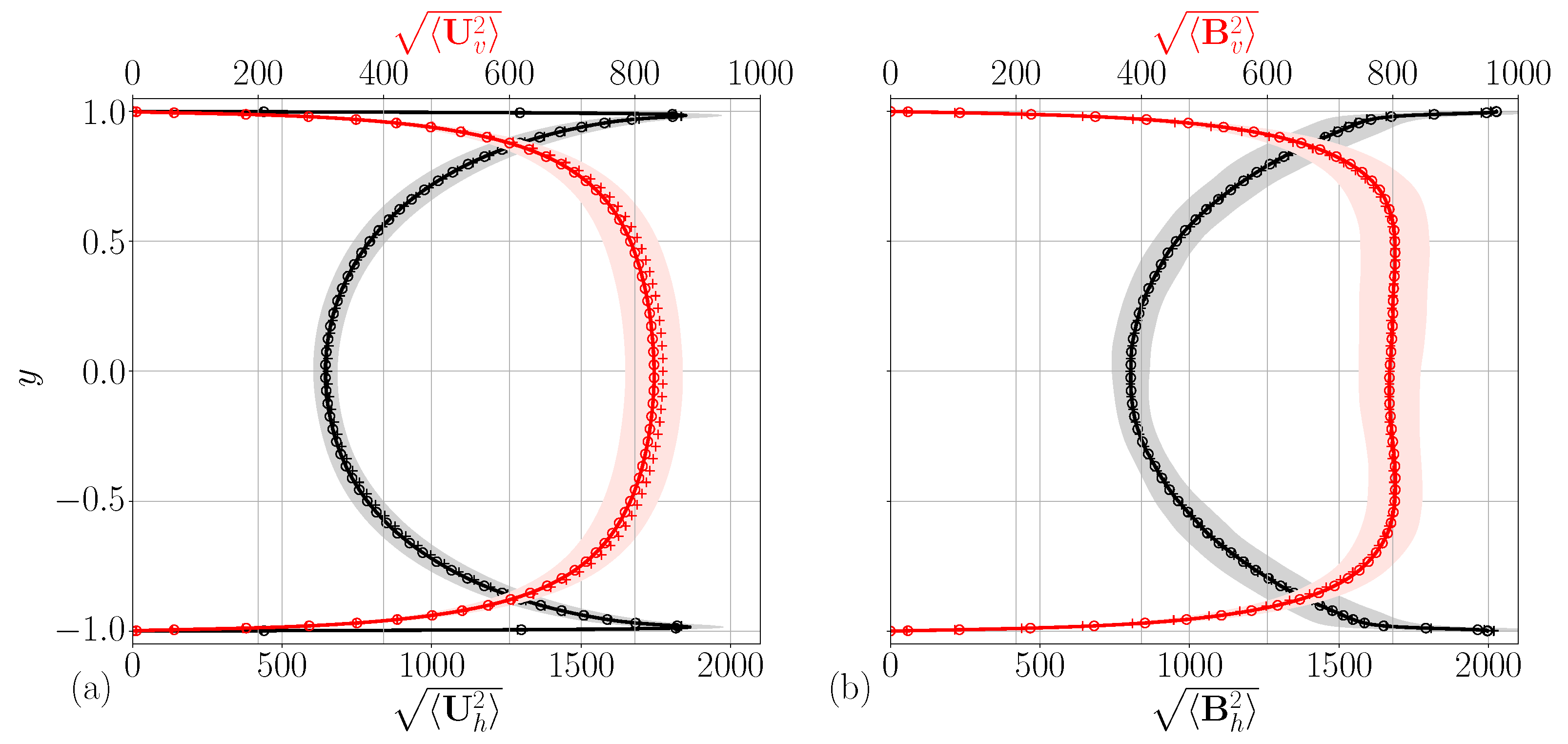
We want to compare DNS statistics of our code in the turbulent regime, including boundary layer phenomenology resolution, with a study which uses the same no-slip, perfectly conducting and isothermal BCs that are used in our problem (20)–(23). In [35], several direct numerical simulations (DNS) for various sets of BCs are presented. This study is based on a modified version of the code presented in [36], which uses poloidal–toroidal decomposition for the magnetic field. The simulation n°9 utilizes the same BCs as implemented and tested here. With their choice of parameters Ra = 5 × 10 8 , Ek = 10 5 , Pr = 1 , Pr m = 2.5 ,   ϕ = π / 2 ,   γ x = 0 L x = L z = 1 ,   a = 0.5 and b = 0.5 , the statistically averaged root mean-square (rms) profiles of vertical and horizontal magnetic fields are computed as
B h = B y 2 , B v = B x 2 + B z 2 .
The horizontal and vertical velocity rms values are computed in the same manner. Since the nondimensionalization used in [35] is based on the thermal diffusion length-scale of the system H 0 * 2 / κ * , we need to convert non-dimensional magnetic field values from free-fall time unit to thermal time unit measurements. Velocities expressed in units of free-fall time need to be multiplied by Ra Pr 22,361 , and magnetic fields—based on the free-fall velocity—need to be multiplied by Ra Pr m / Pr 35,355 . Figure 3 is a reproduction of Figure 6c,f of [35]. It depicts the above-mentioned rms velocity and magnetic field values, scaled to be expressed in the thermal diffusion time units. While the simulation presented in [35] employed a grid with ( N x , N y , N z ) = ( 288 , 256 , 288 ) , we choose a coarser grid which resolution reduced by a factor of two in each direction, resulting in ( N x , N y , N z ) = ( 144 , 127 , 144 ) . This grid reduction is chosen to speed up the simulation, and since the results are already matching within their statistical errors, additional simulations using a finer grid seem unnecessary. The integration time-step is set to Δ t = 2.5 × 10 3 . We compute averages over 2000 snapshots, separeted by a quarter free-fall time unit. As evidenced by the comparison in Figure 3, the rms values of both magnetic fields are almost indistinguishable between our DNS and the the reference simulation from [35]. This good agreement is observed both in the Ekman layer, where the horizontal rms velocity profile experiences strong gradients, and in the bulk. Despite the fundamentally different approach for enforcing the magnetic field to remain divergence free, the validation data clearly lie within one standard deviation of the rms values we computed.

3.3. Energy Equation

To further test the accuracy of our time-stepping scheme, we check the consistency with global conservation law, relating the rate of change of mean magnetic energy to fields themselves. The magnetic energy equation is obtained by multiplying Equation (31) by B , and taking its spatial average yielding an expression for the rate of change of the nondimensionalized magnetic energy as
1 2 t B 2 = U · × B × B η × B 2
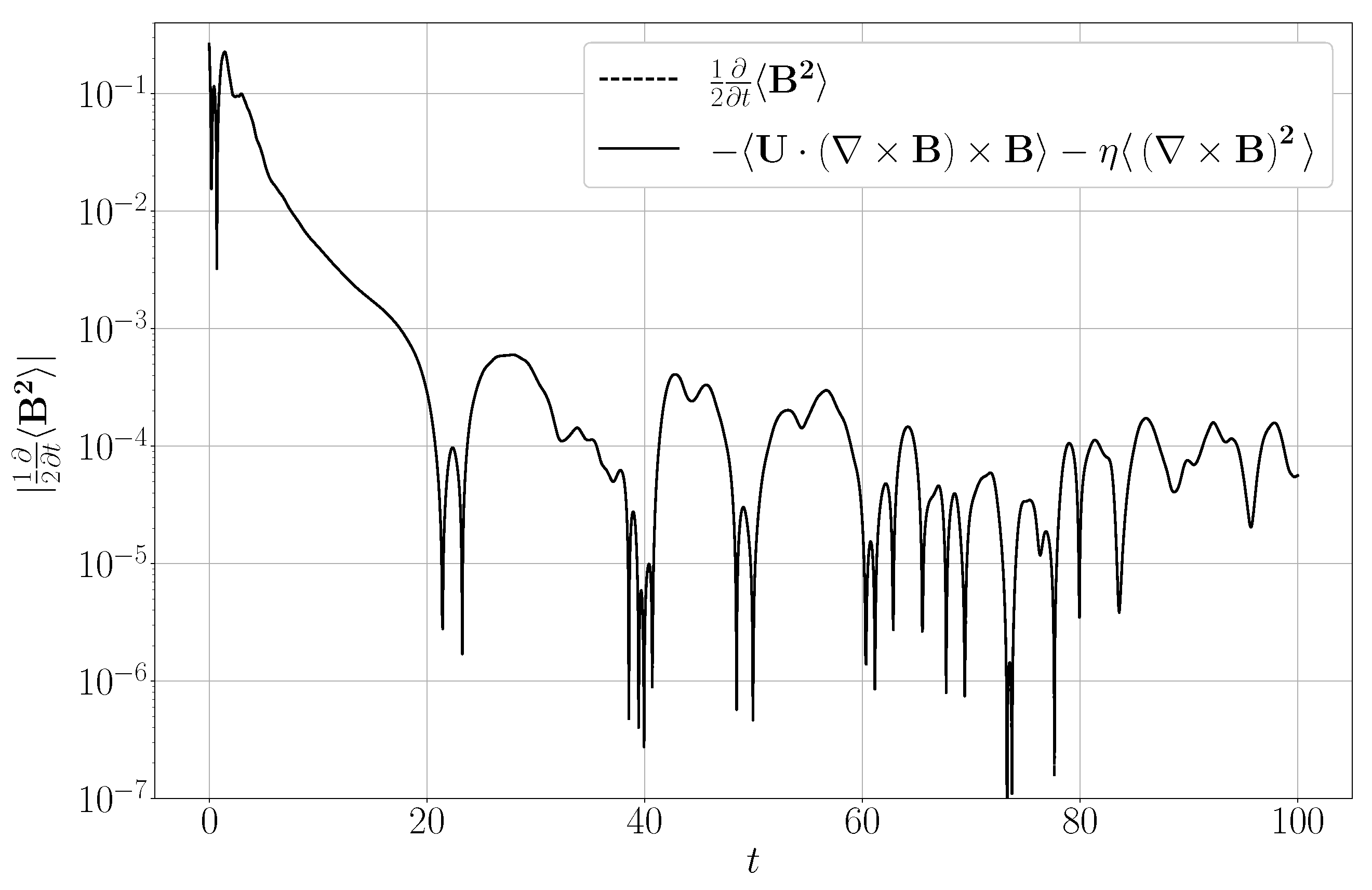
where · 1 L x L z ( b a ) D · d x d y d z is a spatial average over the whole domain. We assume that there are no imposed magnetic fields in (21); hence, the p b surface term vanishes. To check the accuracy at which our numerical scheme satisfies this global conservation law, we compute the rate of change of the magnetic energy on the left-hand side and the terms on the right-hand side independently. Here, derivatives and spatial averages are computed spectrally, while the time derivative of the mean magnetic energy is approximated by centered differences. As shown in Figure 4, the time derivative approximation of the magnetic energy closely matches the sum of the kinetic energy transfer term and ohmic heating term. The relative error is of 10 3 . This error can be rationalized by the lack of precision in the approximation of the time derivative of B 2 . Note that the actual time-stepping code is based on a much more accurate third-order Adams–Bashforth scheme with backwards differentiation [23,37].

3.4. Code Benchmarks

Two different types of benchmark are run to assess the scalability of the code. Both of them use the same physical and numerical parameters for all tests, only varying either the number of processes allocated to it or the grid size of the simulated fields. All the simulations are run on a compute node of the JED cluster (SCITAS, EPFL), which consists in 72 cores of Intel Xeon Platinum 8360Y CPU @ 2.40 GHz, 512 GB of memory and 3.2 TB of NVMe storage [38]. The geometrical parameters used are L x = 1 , L z = 1 and a = 0.5 , b = 0.5 , and the physical ones are Ra = 10 6 , Pr = 1 , Pr m = 1 , Ek = 10 2 , γ x = 0 and ϕ = π / 2 . The wall velocities are kept to zero, and an adverse temperature gradient is maintained as the temperature base state. The numerical integration time-step Δ t is set to 10 3 , and the code is compiled using the mpicxx compiler issued by Intel.
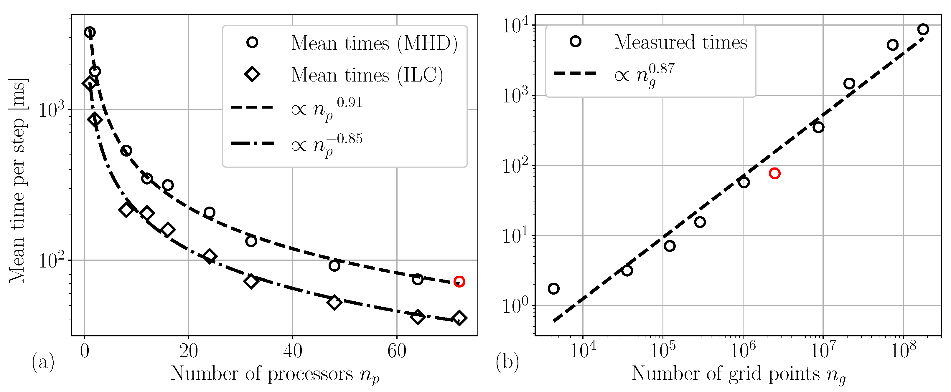
We first test the strong scaling of our code. The grid size is kept fixed at ( N x , N y , N z ) = ( 128 , 127 , 144 ) , which represents approximately 2.34 × 10 6 collocation points. The number of MPI processes allocated to the simulation together with the spatial distribution n p [ n p x , n p z ] are 1 [ 1 , 1 ] , 2 [ 1 , 2 ] , 8 [ 4 , 2 ] , 12 [ 4 , 3 ] , 16 [ 4 , 4 ] , 24 [ 4 , 6 ] , 32 [ 8 , 4 ] , 48 [ 8 , 6 ] , 64 [ 8 , 8 ] and 72 [ 8 , 9 ] . Ideally, the distribution of processes should be as close as possible to the same number in each periodic direction such that the load on each process is equal, but these distributions are solely chosen for benchmarking. The left panel of Figure 5 shows the variation in the mean elapsed time integrating all the fields u , b , θ , p and p b as the number of MPI processes increases from 1 to 72. For comparison, the same benchmark is performed using identical relevant parameters with another ChannelFlow-based code (ILC) that handles the same domain without rotation and magnetic fields and that has been thoroughly tested [6,33].
The dependence of the elapsed time on the number of processes is similar for both cases, the MHD code scaling as Δ t elapsed MHD n p 0.91 and the ILC code as Δ t elapsed ILC n p 0.85 . An ensemble average carried over the mean elapsed times of both cases shows that the MHD code runs 1.9 times slower than the ILC one. With a rough estimate, the MHD and ILC codes, respectively, handle nine and five similar scalar-like fields. Therefore, in principle, the MHD code cannot run faster than 9 / 5 = 1.8 times the runtime of the ILC code. The fact that our code runs only 1.9 times slower is notable, as it indicates that the additional couplings in the equations are not computationally expensive.
The second benchmark assesses weak scaling, keeping the number of MPI processes as well as their distribution fixed to n p [ n p x , n p z ] = 72 [ 8 , 9 ] . The grid size is varied as ( N x , N y , N z ) = ( 16 , 15 , 18 ) , ( 32 , 31 , 36 ) , ( 64 , 63 , 72 ) , ( 128 , 127 , 144 ) , ( 192 , 191 , 216 ) , ( 256 , 255 , 288 ) , ( 384 , 383 , 432 ) and ( 512 , 511 , 588 ) . In the right panel of Figure 5, the mean time per time-step is plotted with respect to the grid size. The scaling of performance with respect to the number of points n g is found to be Δ t elapsed MHD n g 0.87 in the configuration described above.

4. Conclusions and Discussion

We have developed an accurate pseudo-spectral numerical code for the simulation of rotating and convection-driven flow of a conducting Newtonian fluid in a double-periodic wall-bounded domain. The code is based on a primitive variable formulation of the MHD equations and uses a fictitious magnetic pressure to enforce the solenoidal condition of the magnetic field. An extension of the classical influence matrix method with tau correction is derived for general Robin boundary conditions and applied to both velocity and magnetic fields. The accurate scheme is implemented in C++, extending the functionality of the existing parallelized open-source ChannelFlow 2.0 software. Our implementation has been tested against linear stability theory in different scenarios with either imposed magnetic fields or rotation. We successfully reproduced previous results on the statistics of turbulent flows and observed very good agreement when compared to a simulation using an alternative approach for enforcing the magnetic field to remain divergence free. Lastly, the accuracy of the time-marching scheme has been demonstrated by validating it against the analytically derived magnetic energy equation. Additionally, we ran benchmarks demonstrating solid weak and strong scaling of our code. Since the numerical code is (a) accurate, (b) shows favorable parallel scaling, (c) can handle general Robin boundary conditions for both the velocity and magnetic field and (d) can easily interface with Newton-based shooting methods, we expect it to enable the identification and tracking of invariant solutions of rotating MHD in a plane layer.
We believe that the construction of this code opens up the possibility for increased understanding of the interaction of convection with magnetic field in situations relevant to geophysical and astrophysical fluid dynamics, where rotation plays an important role. The local geometry, considered here, is often utilized for modeling turbulent interactions; the accurate and efficient methods described here, coupled with the possibility of the detection of exact nonlinear solutions, will enable us to determine better the nature of transport and dynamo action in such rotating magnetized systems as the interior of planets and stars.

Author Contributions

Methodology, J.-C.R.; Software, J.-C.R.; Writing—original draft, J.-C.R.; Writing—review & editing, S.M.T. and T.M.S.; Supervision, T.M.S. All authors have read and agreed to the published version of the manuscript.

Funding

This work was supported by the European Research Council (ERC) under the European Union’s Horizon 2020 research and innovation programme (grant no. 865677).

Data Availability Statement

The data that support the findings of this study are available from the corresponding author upon reasonable request.

Conflicts of Interest

The authors declare no conflicts of interest. The funders had no role in the design of the study; in the collection, analyses, or interpretation of data; in the writing of the manuscript; or in the decision to publish the results.

References

  1. Hathaway, D.H. The Solar Cycle. Living Rev. Sol. Phys. 2015, 12, 4. [Google Scholar] [CrossRef]
  2. McElhinny, M.W.; Senanayake, W.E. Paleomagnetic evidence for the existence of the geomagnetic field 3.5 Ga ago. J. Geophys. Res. 1980, 85, 3523–3528. [Google Scholar] [CrossRef]
  3. Kivelson, M.G.; Khurana, K.K.; Volwerk, M. The Permanent and Inductive Magnetic Moments of Ganymede. Icarus 2002, 157, 507–522. [Google Scholar] [CrossRef]
  4. Ashtari, O.; Schneider, T.M. Identifying invariant solutions of wall-bounded three-dimensional shear flows using robust adjoint-based variational techniques. J. Fluid Mech. 2023, 977, A7. [Google Scholar] [CrossRef]
  5. Nagata, M. Three-dimensional finite-amplitude solutions in plane Couette flow: Bifurcation from infinity. J. Fluid Mech. 1990, 217, 519–527. [Google Scholar] [CrossRef]
  6. Reetz, F.; Schneider, T.M. Invariant states in inclined layer convection. Part 1. Temporal transitions along dynamical connections between invariant states. J. Fluid Mech. 2020, 898, A22. [Google Scholar] [CrossRef]
  7. Feudel, F.; Tuckerman, L.S.; Zaks, M.; Hollerbach, R. Hysteresis of dynamos in rotating spherical shell convection. Phys. Rev. Fluids 2017, 2, 053902. [Google Scholar] [CrossRef]
  8. Skene, C.S.; Marcotte, F.; Tobias, S.M. On nonlinear transitions, minimal seeds and exact solutions for the geodynamo. arXiv 2024, arXiv:2411.05499v2. [Google Scholar] [CrossRef]
  9. Naskar, S.; Pal, A. Direct numerical simulations of optimal thermal convection in rotating plane layer dynamos. J. Fluid Mech. 2022, 942, A37. [Google Scholar] [CrossRef]
  10. Stellmach, S.; Hansen, U. Cartesian convection driven dynamos at low Ekman number. Phys. Rev. E 2004, 70, 056312. [Google Scholar] [CrossRef]
  11. Chandrasekhar, S. Hydrodynamic and Hydromagnetic Stability; Oxford University Press: London, UK, 1961. [Google Scholar]
  12. Weiss, N.O.; Proctor, M.R.E. Magnetoconvection; Cambridge University Press: Cambridge, UK, 2014. [Google Scholar]
  13. Cooper, R.G.; Bushby, P.J.; Guervilly, C. Subcritical dynamos in rapidly rotating planar convection. Phys. Rev. Fluids 2020, 5, 113702. [Google Scholar] [CrossRef]
  14. Roberts, P.H. Diffusive instabilities in magnetohydrodynamic convection. In Les Instabilitiés Hydrodynamiques en Convection Libre, Forcée et Mixte; Legros, J.C., Platten, J.K., Eds.; Springer: Berlin/Heidelberg, Germany, 1978; pp. 102–111. [Google Scholar]
  15. Kleiser, L.; Schumann, U. Treatment of Incompressibility and Boundary Conditions in 3-D Numerical Spectral Simulations of Plane Channel Flows. In Proceedings of the Third GAMM—Conference on Numerical Methods in Fluid Mechanics, Cologne, Germany, 10–12 October 1979; Hirschel, E.H., Ed.; Vieweg+Teubner Verlag: Wiesbaden, Germany, 1980; pp. 165–173. [Google Scholar]
  16. ChannelFlow 2.0. Available online: https://www.channelflow.ch/ (accessed on 27 March 2025).
  17. Gibson, J.F.; Reetz, F.; Azimi, S.; Ferraro, A.; Kreilos, T.; Schrobsdorff, H.; Farano, M.; Yesil, A.F.; Schütz, S.S.; Culpo, M.; et al. Channelflow 2.0. 2019; manuscript in preparation. [Google Scholar]
  18. Chen, F.F. Introduction to Plasma Physics and Controlled Fusion, 3rd ed.; Springer: Cham, Switzerland, 2015. [Google Scholar]
  19. Arter, W. Nonlinear Convection in an Imposed Horizontal Magnetic Field. Geophys. Astrophys. Fluid Dyn. 1983, 25, 259–292. [Google Scholar] [CrossRef]
  20. Weiss, N.O. Convection in an imposed magnetic field. Part 1. The development of nonlinear convection. J. Fluid Mech. 1981, 108, 247–272. [Google Scholar] [CrossRef]
  21. Tobias, S.M. The turbulent dynamo. J. Fluid Mech. 2021, 912, P1. [Google Scholar] [CrossRef]
  22. Bader, S.H.; Zhu, Z. AFiD-MHD: A finite difference method for magnetohydrodynamic flows. J. Comput. Phys. 2005, 523, 113658. [Google Scholar] [CrossRef]
  23. Peyret, R. Spectral Methods for Incompressible Viscous Flow; Applied Mathematical Sciences; Springer: New York, NY, USA, 2002; Volume 148. [Google Scholar]
  24. Tenam, R. Navier-Stokes Equations: Theory and Numerical Analysis, 3rd ed.; American Mathematical Society: Providence, RI, USA, 2001. [Google Scholar]
  25. Eriksson, K.; Estep, D.; Hansbo, P.; Johnson, C. Computational Differential Equations; Cambridge University Press: Cambridge, UK, 1996. [Google Scholar]
  26. Min, T.; Kim, J. Effects of hydrophobic surface on skin-friction drag. Phys. Fluids 2004, 16, L55–L58. [Google Scholar] [CrossRef]
  27. Liu, X. Extension of Kleiser & Schumann’s influence-matrix method for generalized velocity boundary conditions. J. Comput. Phys. 2011, 230, 7911–7916. [Google Scholar]
  28. Canuto, C.; Hussaini, Y.M.; Quarteroni, A.; Zang, T.A. Spectral Methods in Fluid Dynamics; Springer: Berlin/Heidelberg, Germany, 1988. [Google Scholar]
  29. Tuckerman, L.S. Divergence-free Velocity Fields in Nonperiodic Geometries. J. Comput. Phys. 1989, 80, 403–441. [Google Scholar] [CrossRef]
  30. Message Passing Interface Forum. MPI: A Message-Passing Interface Standard, Version 3.1; High Performance Computing Center Stuttgart (HLRS): Stuttgart, Germany, 2015. [Google Scholar]
  31. Reetz, F.; Kreilos, T.; Schneider, T.M. Exact invariant solution reveals the origin of self-organized oblique turbulent-laminar stripes. Nat. Commun. 2019, 10, 2277. [Google Scholar] [CrossRef]
  32. Ferraro, A. Exploiting Marginal Stability in Slow-Fast Quasilinear Dynamical Systems. Ph.D. Thesis, EPFL, Lausanne, Switzerland, 2022. [Google Scholar]
  33. Reetz, F. Turbulent Patterns in Wall-Bounded Shear Flows: Invariant Solutions and Their Bifurcations. Ph.D. Thesis, EPFL, Lausanne, Switzerland, 2019. [Google Scholar]
  34. Zheng, Z.; Tuckerman, L.S.; Schneider, T.M. Natural convection in a vertical channel. Part 2. Oblique solutions and global bifurcations in a spanwise-extended domain. J. Fluid Mech. 2024, 1000, A29. [Google Scholar] [CrossRef]
  35. Kolhey, P.; Stellmach, S.; Heyner, D. Influence of boundary conditions on rapidly rotating convection and its dynamo action in a plane fluid layer. Phys. Rev. Fluids 2022, 7, 043502. [Google Scholar] [CrossRef]
  36. Stellmach, S.; Hansen, U. An efficient spectral method for the simulation of dynamos in Cartesian geometry and its implementation on massively parallel computers. Geochem. Geophys. Geosystems 2008, 9, Q05003. [Google Scholar] [CrossRef]
  37. Gibson, J.F. ChannelFlow User Guide 0.9.18 2009. Available online: http://channelflow.org/dokuwiki/doku.php?id=docs (accessed on 25 November 2024).
  38. SCITAS JED Documentation, EPFL. Available online: https://scitas-doc.epfl.ch/supercomputers/jed/ (accessed on 14 November 2024).
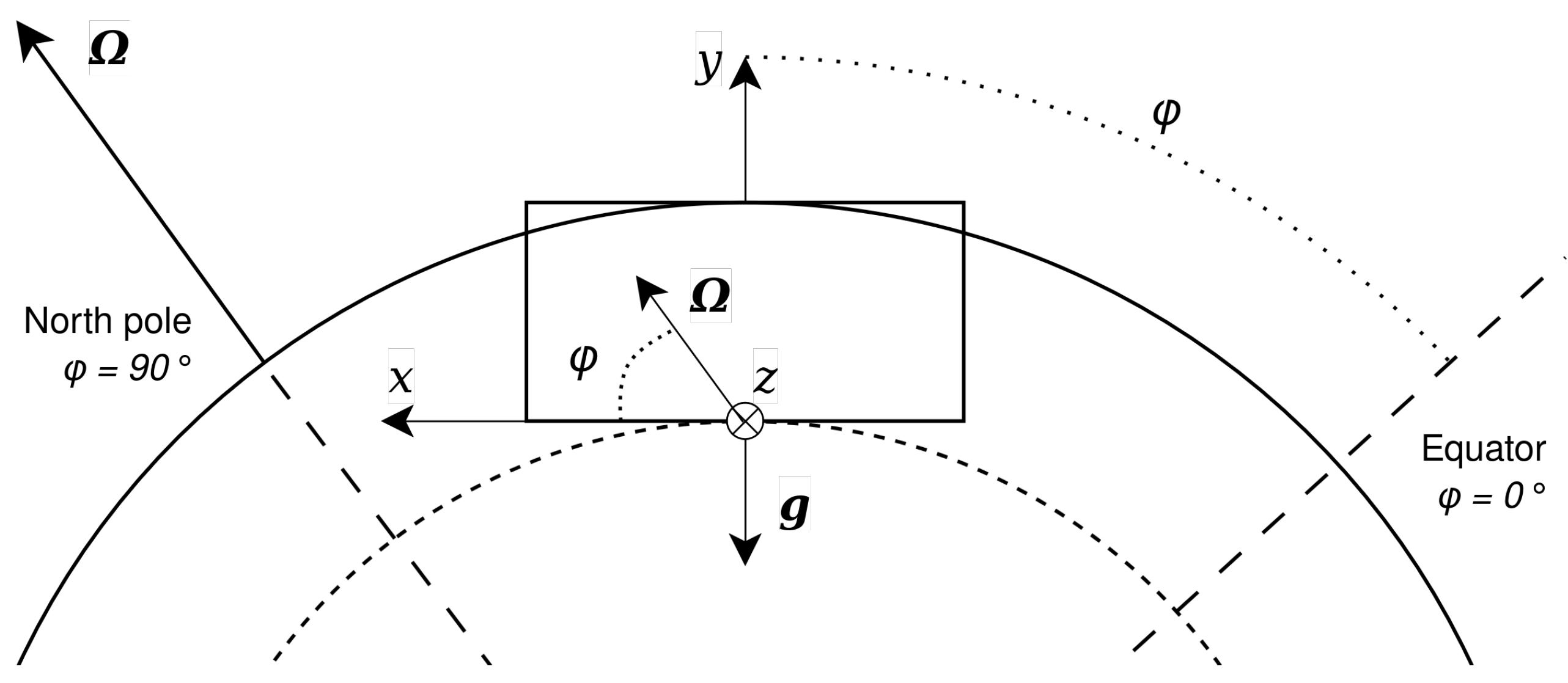
Figure 1. Interpretation of the channel geometry as the portion of an astrophysical body’s convective rotating flow chosen at a specific latitude angle ϕ . At the north pole, the rotation vector Ω is vertical, and it is horizontal at the equator.
Mathematics 13 02549 g001
Figure 2. Domain-considered, doubly periodic in the two horizontal directions and wall-bounded in the vertical one. The streamwise direction (x) has an extent of L x , the spanwise direction (z) has an extent of L z and the vertical direction (y) has an extent of L y = b a .
Mathematics 13 02549 g002
Figure 3. (a) U h and U v are the horizontal and vertical rms values of velocity. (b) B h and B v are the horizontal and vertical rms values of the magnetic field, respectively. Horizontal velocity and magnetic field rms values are depicted in black, and vertical rms values in red. All fields in this figure are scaled to thermal time-scale. Circles represent our simulation data and pluses the data of [35]. The lightly-colored bands are the statistical standard deviations. For visibility reasons, only every second points is marked with a circle whereas the reference figure, with a grid twice refined in each direction, shows one every four points.
Mathematics 13 02549 g003
Figure 4. Absolute value of the time derivative of magnetic energy, approximated by centered differences as well as by the sum of components on the right-hand side of (72). The geometrical parameters used for this simulation are L x = L z = 5 , a = 0.5 and b = 0.5 , the physical ones are Ra = 5 × 10 5 , Ek = 2 × 10 2 , Pr = 1 , Pr m = 1 , γ x = 0 and ϕ = π / 2 . The grid size is set to ( N x , N y , N z ) = ( 48 , 47 , 48 ) and the integration time-step to Δ t = 2.5 × 10 3 .
Mathematics 13 02549 g004
Figure 5. (a) Mean time spent per time-step as a function of the number of MPI processes used. For comparison purposes, mean times are shown both for the MHD code and for the ILC code. The relative standard deviations range from 15 to 1%. (b) Mean time spent per time-step as a function of the grid size. The standard deviation is of the order of 100 % for the lower grid sizes, as fluctuations on such of a short duration have a strong influence, and reaches values of around 0.5 % for larger grid sizes. On both panels, the red circle corresponds to the same simulation case of n p = 72 and n g = 128 × 127 × 144 2.34 × 10 6 .
Mathematics 13 02549 g005
Table 1. Linear stability tests against linear stability theory [11], using the same rounding. Grid size values represent N x × N y × N z , and the Taylor number is related to the Ekman number as Ta = 4 / E k 2 .
Parameter a c Theoretical Ra c Obtained Ra c Rel. ErrorGrid Size
3.117 1707.762 1707.762 6 × 10 8 32 × 31 × 32
8.00 7084.51 7084.51 1 × 10 8 32 × 31 × 32
Ta = 5000 4.25 3468.6 3468.6 8 × 10 5 32 × 31 × 32
Ta = 500 3.30 1940.3 1940.3 1 × 10 8 32 × 31 × 32
Ta = 10 5 7.20 16,72116,720 7 × 10 5 32 × 31 × 32
Ta = 10 10 55.5 3.4574 × 10 7 3.4498 × 10 7 6 × 10 3 48 × 47 × 48
Q = 100 4.00 3757.3 3757.3 5 × 10 6 64 × 33 × 64
Q = 1000 5.80 17,10317,103 3 × 10 6 64 × 63 × 64
Q = 10 4 8.66 124,508124,509 1 × 10 5 64 × 63 × 64
Disclaimer/Publisher’s Note: The statements, opinions and data contained in all publications are solely those of the individual author(s) and contributor(s) and not of MDPI and/or the editor(s). MDPI and/or the editor(s) disclaim responsibility for any injury to people or property resulting from any ideas, methods, instructions or products referred to in the content.