Article

Adaptive Control for Constrained Nonlinear Systems Under Deception Attacks and Actuator Saturation

1
School of Information Science and Engineering, Shandong Normal University, Jinan 250014, China
2
School of Control Science and Engineering, Dalian University of Technology, Dalian 116024, China
*
Author to whom correspondence should be addressed.
Mathematics 2025, 13(21), 3508; https://doi.org/10.3390/math13213508
Submission received: 2 September 2025 / Revised: 29 October 2025 / Accepted: 30 October 2025 / Published: 2 November 2025

Abstract

This paper proposes an adaptive control framework for constrained nonlinear systems subject to sensor and actuator deception attacks, in the presence of actuator saturation. To enforce state constraints under sensor attacks, a modified coordinate transformation is integrated with a barrier Lyapunov function (BLF) design, ensuring controller feasibility and constraint satisfaction even when state measurements are compromised. Moreover, the compounded effects of actuator saturation and actuator-side attacks are explicitly analyzed within a unified BLF framework, and an adaptive decoupling-compensation strategy is introduced to mitigate their influence. Simulation results demonstrate the effectiveness and robustness of the proposed approach.

1. Introduction

Cyber–physical systems (CPSs) represent a transformative integration of computation, networking, and physical processes. As CPSs become increasingly embedded in critical infrastructures, ensuring their security and operational reliability has become a pressing research issue [1,2,3,4,5,6,7,8,9]. Recent research has explored various cyber threats, including replay, denial-of-service, and deception attacks [1,2,3]. Among these, deception attacks that manipulate sensor or controller signals to covertly alter control behavior are particularly insidious [10,11]. To mitigate such attacks, techniques such as observer-based event-triggered PID control [1] and adaptive correction-based strategies [4] have been proposed. However, many existing solutions are tailored to linear systems and do not generalize well to nonlinear CPSs. To enhance resilience against such attacks, adaptive control has long been regarded as a fundamental methodology. Classical adaptive control approaches include dual control [12], self-tuning regulators [13], model reference adaptive control (MRAC) [14], and gain scheduling [15], which have been extensively applied to linear and weakly nonlinear systems. However, these classical methods are not directly applicable to constrained nonlinear CPSs operating under adversarial conditions. Motivated by this limitation, researchers have explored more advanced adaptive strategies tailored to nonlinear systems. For example, Ren et al. [5] employed Nussbaum-type functions to compensate for false data injection attacks with unknown dynamics. Other efforts include neural network-based compensation for time-varying attacks [7] and prescribed-time consensus for multi-agent systems [9]. Despite such progress, these studies typically address isolated attack types and often overlook the compounded effect of cyber threats under state constraints—a critical aspect in safety-critical applications.
Physical constraints such as position, velocity, and temperature naturally arise in many CPSs (e.g., UAVs, industrial robots, medical devices), and failure to enforce such constraints can lead to catastrophic failures [16]. The barrier Lyapunov function (BLF) method [17] has been widely adopted for control design with state constraints in nonlinear systems [18,19,20,21,22,23,24]. However, classical BLF methods often impose feasibility conditions on virtual control signals, which typically require conservative offline tuning. Zhao et al. [25] proposed a nonlinear coordinate transformation to alleviate these feasibility conditions. Furthermore, Yuan et al. [21] developed a fixed-time BLF scheme ensuring both control sginals and actual states remain within constraints. Nevertheless, in the context of secure control, existing BLF-based methods seldom consider sensor-side deception attacks, particularly how such attacks influence feasibility and constraint enforcement. To our knowledge, no prior work has rigorously investigated the feasibility of BLF-based controllers under sensor-channel deception.
In addition to state constraints, actuator saturation is another critical physical nonlinearity widely observed in practice—for instance, when motors or generators reach their maximum torque or power limits. This issue has motivated a variety of strategies, including auxiliary-system approaches [26], smooth approximations [27], and neuro-adaptive learning-based methods [28]. In particular, smooth approximations (e.g., Gaussian [29], hyperbolic tangent [27]) are often used to incorporate actuator saturation into backstepping designs. Fixed-time and fuzzy adaptive designs under input saturation have also been explored [30,31,32,33]. However, these studies primarily handle saturation in isolation, assuming controller outputs are trustworthy. In practice, actuator-side deception attacks can manipulate control commands before they reach the actuators, inducing premature saturation or persistent overdriving. This coupling between deception and saturation can severely degrade control performance or even destabilize the system. For example, in UAVs, forged control signals may repeatedly exceed the actuator’s upper operational limit, leading to persistent saturation where the actuator output fails to respond.
Despite the growing importance of both deception attacks and actuator saturation, their combined impact remains underexplored. To our knowledge, no existing work provides a unified framework capable of handling their joint effects. Motivated by these interconnected challenges, this paper develops a novel adaptive control framework for nonlinear CPSs that simultaneously addresses three critical aspects: (i) dual-channel deception attacks, (ii) state constraints, and (iii) actuator saturation. The main contributions are summarized as follows:
  • To handle sensor deception attack while enforcing state constraints, a modified coordinate transformation is proposed, upon which a BLF structure is constructed. Compared with existing BLF-based methods [21,34], the proposed approach preserves both state constraint satisfaction and BLF feasibility even when state measurements are corrupted—an interdependent issue not sufficiently addressed in prior works.
  • Unlike previous research that investigates actuator saturation [27] and controller deception attacks [22] separately, this work analyzes their compounded influence within a unified BLF framework. An adaptive decoupling-compensation strategy is developed to mitigate these effects separately, thereby enhancing robustness under adversarial actuator conditions.

Notations

Throughout this paper, R denotes the set of real numbers, and R n represents the set of n × 1 real column vectors. The vector x ¯ i is defined as [ x 1 , x 2 , , x i ] T R i . The 1-norm and -norm of a vector are denoted by · 1 and · , respectively. For a vector B = [ b 1 , b 2 , , b n ] R n , they are defined as B 1 = i = 1 n | b i | and B = max 1 i n | b i | . The operator vec j = 1 , , l ( ϕ j ) denotes the vector [ ϕ 1 , ϕ 2 , , ϕ l ] , and vec l ( k ) represents [ k , , k ] R l . Hereafter, to simplify notation, function arguments may be omitted whenever no ambiguity arises.

2. Problem Formulation

In this article, we focus on a class of nonlinear CPSs governed by the following dynamical model:
x ˙ i ( t ) = f i ( x ¯ i ( t ) ) + x i + 1 ( t ) , i = 1 , 2 , , n 1 , x ˙ n ( t ) = f n ( x ¯ n ( t ) ) + sat ( u ( t ) ) ,
where x i ( t ) R represents a system state, and u ( t ) R denotes the received control signal. The term sat ( u ( t ) ) R represents the saturated output of the actuator, which serves as the actual input to the system (1), f i ( · ) R and f n ( · ) R represent the system’s nonlinearities.
In this work, we assume that the communication platforms of the sensors and actuator can be compromised by attackers. The modeling of the deception attacks is given by [6,7]:
x ˇ i ( t ) = x i ( t ) + ω s ( t ) x i ( t ) , i = 1 , 2 , , n , u ( t ) = g u ( t ) v ( t ) + ω a ( t ) f a ( x ¯ n ( t ) ) ,
where x ˇ i R , ω s R represent disrupted state measurements, unknown sensor attack gain, respectively. v R is a control law to be designed. g u R and ω a R denote the unknown input attack gains, f a ( · ) is a nonlinear function. We define λ = 1 + ω s such that x ˇ i = λ x i , where x ˇ i are available for controller design.
Assumption 1
([34]). There exists a known positive constant β and unknown positive constants γ, λ 0 , g u ̲ and g u ¯ such that β λ γ , | λ ˙ λ 1 | λ 0 and g u ̲ g u ( t ) g u ¯ .
Remark 1.
In many practical applications, maintaining stealth is critical for successful deception attacks. Meanwhile, attackers possess finite resources to manipulate sensor/actuator signals, so the attack gains ω s ( t ) and g u ( t ) cannot be unbounded. When ω s ( t ) 1 (i.e., λ ( t ) 0 ), x ˇ i loses all correlation with the true state x i , making stabilization via any control law v ( t ) based on x ˇ i theoretically impossible. Given the limited capabilities of attackers and the minimal ability to retain observations of the true state of the controller, Assumption 1 formalizes these physical and adversarial constraints to enable controller synthesis under realistic attack conditions. From Assumption 1, the corrupted state signals satisfy β | x i | | x ˇ i | γ | x i | , where β and γ characterizes the fidelity of sensor signals under potential attacks. The sensor attack model adopted in this paper is also applicable to modeling sensor faults or unknown sensor sensitivity.
All states in systems (1) are constrained as:
l i < x i ( t ) < l i , i = 1 , 2 , , n ,
where l i > 0 represent predefined constraint boundaries, the initial value satisfies l i < x i ( 0 ) < l i .
The actuator saturation is modeled as:
sat ( u ) = sign ( u ) · min | u | , l 0 ,
where l 0 > 0 is the saturation threshold.
  Control Objective: Design an adaptive control law v ( t ) such that under dual-channel deception attacks (2), state constraints (3) and actuator saturation (4), (i) all closed-loop signals remain uniformly ultimately bounded; (ii) system states satisfy (3) for all t 0 .

3. Main Results

The considered cyber–physical system consists of three interacting layers: a physical layer, a communication layer, and a control layer. In the physical layer, the nonlinear plant evolves under state constraints and actuator saturation. The communication layer is susceptible to sensor- and actuator-side deception attacks that distort transmitted state measurements and control commands.
To address these challenges, this section develops an adaptive secure control strategy that integrates modified coordinate transformations and BLF design to ensure constraint satisfaction, together with adaptive compensation to maintain robustness against compounded deception-saturation effects. The technical components are organized as follows: Section 3.1 presents a smooth saturation approximation for actuator nonlinearities; Section 3.2 introduces modified coordinate transformations that eliminate BLF feasibility restrictions under attacks; Section 3.3 constructs BLFs with guaranteed feasibility for constrained states; Section 3.4 details adaptive controller synthesis and compensation design; and Section 3.5 establishes closed-loop stability through Lyapunov analysis. Some useful lemmas are provided in Appendix A.

3.1. Saturation Approximation

The actuator of system (1) is subject to saturation constraints. We define the following smooth function to approximate the saturation characteristics:
M u ( u ) = l 0 erf u 0 ,
where erf ( x ) = 2 π 0 x e r 2 d r is the Gaussian error function, 0 = 2 δ 0 l 0 / π and δ 0 is a tuning parameter. Thus, sat ( u ) can be expressed as:
sat ( u ) = M u ( u ) + Δ ( u ) ,
where Δ ( u ) denotes the bounded approximation error with | Δ ( u ) | Δ ¯ for a positive constant Δ ¯ . Figure 1 shows the trajectories of the saturation function (4), the widely used tanh-based saturation approximator [27], and the proposed approximator (5) under δ 0 = 0.9 and l 0 = 5 . It can be observed that the proposed approximation can generate smaller approximation errors.
From the saturation approximation (6), applying the mean-value theorem to M u ( u ) , for any u R , there exists ε 0 ( 0 , 1 ) such that:
M u ( u ) = M u ( 0 ) + M u u | u = u ε · u ,
where u ε = ε 0 u . With M u ( 0 ) = 0 and η u ( u ε ) : = exp ( u ε 2 / i 2 ) , the expression reduces to:
M u ( u ) = η u ( u ε ) u .

3.2. Modified Transformations

To prevent virtual controllers x i * from violating corresponding state constraints, we replace x i * within the state transformation by a constrained surrogate M i ( x i * ) inspired by the approximation (5):
ζ 1 = x 1 , ζ i = x i 1 λ M i ( x i * ) , i = 2 , 3 , , n ,
where M i ( x i * ) denotes a smooth saturation function defined as:
M i ( x i * ) = m i erf x i * i .
The M i ( x i * ) is bounded and satisfies | M i ( x i * ) | < m i for some design parameter m i > 0 , and i = δ i m i / π . Analogous to (7), for any x i * , there exists ε i ( 0 , 1 ) such that
M i ( x i * ) = η i ( x i , ε * ) · x i * ,
where η i ( x i , ε * ) = exp x i , ε * 2 / i 2 and x i , ε * = ε i x i * . From the properties of η i , there exist constants μ i 1 > 0 such that η i μ i 1 and η u μ n for i = 2 , , n .
Under sensor deception attacks, the actual state x i becomes unavailable. We therefore construct the measurable transformed states:
z i = λ ζ i = x ˇ i M i ( x i * ) , i = 1 , 2 , , n ,
where z 1 = x ˇ 1 follows directly. Unlike conventional transformations that rely on true states, the proposed form is constructed using the measurable signal x ˇ i and the smooth compensation term M i , ensuring feasibility even under attacks (See Remark 2).

3.3. Barrier Lyapunov Function

Given the use of the BLF approach for controller design and the symmetric constraints on system states, we define the constraint requirements on z i as
D i < z i < D i , i = 1 , 2 , , n ,
where D i > 0 are the boundaries of z i to be designed. Then, we select the following rational-type barrier Lyapunov functions:
V ¯ i = 1 2 ξ i 2 ,
where ξ i = D i 2 z i / ( D i 2 z i 2 ) , and the sets Ω z , i = { | z i | < D i } are delineated. For a given i, provided that the initial condition | z i ( 0 ) | < D i is satisfied, the function V ¯ i remains well-defined for t [ 0 , ) . As z i approaches ± D i , V ¯ i tends to infinity. Ensuring the boundedness of V ¯ i guarantees that z i remains within Ω z , i for all t > 0 . The time derivative of the selected BLFs can be calculated as:
V ¯ ˙ i = Ω i ξ i z ˙ i ,
where Ω i = D i 2 ( D i 2 + z i 2 ) / ( D i 2 z i 2 ) 2 .
To account for approximation errors and attack transients, we design D i = κ i l i m i , with m 1 = 0 and κ i ( 0 , β ) . When | z i | < D i holds, we know that
| x i | 1 λ | z i + M i | κ i λ l i + 1 λ ( | M i | m i ) l i .
Hence, maintaining the BLFs (13) bounded ensures that the full-state constraints (3) are satisfied.
Remark 2.
Conventional BLF-based designs face two intertwined challenges under deception attacks: (1) The true states x i are replaced by the corrupted measurements x ˇ i , making the direct enforcement of | x i | < l i infeasible. (2) Virtual Control Admissibility: The virtual control x i * must satisfy | x i * | < l i throughout, known as the feasibility condition of BLF approach [25], often requiring conservative offline tuning or even becoming unsatisfiable in practice. The proposed coordinate transformation resolves both challenges simultaneously. First, by constructing z i based solely on the measurable x ˇ i , all constraints are shifted to available quantities, preserving feasibility under bounded attacks. Second, by embedding the smooth compensation term M i ( x i * ) with m i = κ i l i ϱ i > 0 , the transformed variable automatically satisfies the admissible range with a small safety margin ϱ i > 0 , thereby removing the need for feasibility assumptions on x i * even under attacks. As verified in Section 4, without M i ( x i * ) (as in many existing works), both x i * and x i can violate | x i | < l i , whereas the proposed design ensures all states remain strictly within the prescribed bounds, confirming its effectiveness.

3.4. Controller Design

Firstly, in scenarios where deception attacks and actuator saturation are present, the dynamics of the compromised states x ˇ i , x ˇ n for i = 1 , 2 , , n 1 , can be described by their respective time derivatives. These derivatives are formulated as follows:
x ˇ ˙ i = λ ˙ x i + λ x ˙ i = x ˇ i + 1 + λ ˙ λ 1 x ˇ i + λ f i , i = 1 , 2 , , n 1 , x ˇ ˙ n = λ ˙ x n + λ x ˙ n = λ · sat ( u ) + λ ˙ λ 1 x ˇ n + λ f n .
Applying Lemma A2 to f i ( x ¯ i ) , there exist an unknown positive constant ϖ ¯ i and a known smooth function ρ i ( x ˇ ¯ i ) > 1 such that f i ( x ¯ i ) ϖ i ( λ 1 ) ρ i ( x ˇ ¯ i ) ϖ ¯ i ρ i ( x ˇ ¯ i ) , where ϖ i ( λ 1 ) 1 . This bound holds for all i = 1 , 2 , , n .
  • Step 1:
Under the modified coordinate transformation (11) where z 1 = x ˇ 1 , along the first subsystem of (16), the time derivative of z 1 is given by:
z ˙ 1 = x ˇ 2 + λ ˙ λ 1 x ˇ 1 + λ f 1 ( x 1 ) = M 2 ( x 2 * ) + z 2 + λ ˙ λ 1 x ˇ 1 + λ f 1 ( x 1 ) .
Here, we define θ ^ 1 as the estimation of an unknown constant θ 1 , which will be specified later; the estimate error are θ ˜ 1 = θ 1 θ ^ 1 . Then, we consider the first Lyapunov function candidate V 1 as
V 1 = V ¯ 1 + 1 2 μ 1 θ ˜ 1 2 .
Utilizing (14) and (17), the time derivative of V 1 is deduced as
V 1 ˙ = Ω 1 ξ 1 z ˙ 1 μ 1 θ ˜ 1 θ ^ ˙ 1 = Ω 1 ξ 1 M 2 ( x 2 * ) + Ω 1 ξ 1 λ ˙ λ 1 x ˇ 1 + Ω 1 ξ 1 λ f 1 + Ω 1 ξ 1 z 2 μ 1 θ ˜ 1 θ ^ ˙ 1 .
For the term Ω 1 ξ 1 λ ˙ λ 1 x ˇ 1 , by applying Lemma A1 in our Appendix A with α = β = 2 and ε = 1 , we obtain
Ω 1 ξ 1 λ ˙ λ 1 x ˇ 1 Ω 1 | ξ 1 | | λ ˙ λ 1 | | x ˇ 1 | Ω 1 | ξ 1 | λ 0 1 2 x ˇ 1 2 + 1 2 = Ω 1 | ξ 1 | λ 0 1 2 ( x ˇ 1 2 + 1 ) ,
and for the term Ω 1 ξ 1 λ f 1 , by using Lemma A2 in our Appendix A, it follows that
Ω 1 ξ 1 λ f 1 Ω 1 | ξ 1 | | λ | ϖ 1 ( λ 1 ) ρ i ( x ˇ 1 ) Ω 1 | ξ 1 | λ ¯ ϖ ¯ 1 ρ 1 ( x ˇ 1 ) .
Then, using Lemma A3 in our Appendix A and substituting these bounds, one obtains
Ω 1 ξ 1 λ ˙ λ 1 x ˇ 1 + Ω 1 ξ 1 λ f 1 ( x 1 ) Ω 1 | ξ 1 | Λ 1 T P 1 Ω 1 ξ 1 θ 1 μ 1 Φ 1 tanh Ω 1 ξ 1 Φ 1 τ 1 + θ 1 μ 1 τ 1 ς ,
where τ 1 is a positive constant, Λ 1 = [ 1 2 λ 0 , λ ¯ ϖ ¯ 1 ] T , P 1 = [ x ˇ 1 2 + 1 , ρ 1 ( x ˇ 1 ) ] T , θ 1 = Λ 1 / μ 1 and Φ 1 = P 1 1 .
Substituting (19) into (18), we can obtain that
V 1 ˙ Ω 1 ξ 1 θ 1 μ 1 Φ 1 tanh Ω 1 ξ 1 Φ 1 τ 1 + Ω 1 ξ 1 M 2 ( x 2 * ) + Ω 1 ξ 1 z 2 μ 1 θ ˜ 1 θ ^ ˙ 1 + θ 1 μ 1 τ 1 ς .
The ideal virtual controller x 2 * and the adaptive law of θ ^ 1 are designed as:
x 2 * = 1 Ω 1 θ ^ 1 Φ 1 Ω 1 tanh Ω 1 ξ 1 Φ 1 τ 1 + k 1 ξ 1 ,
θ ^ ˙ 1 = σ 1 θ ^ 1 + Ω 1 ξ 1 Φ 1 tanh Ω 1 ξ 1 Φ 1 τ 1 , θ ^ 1 ( 0 ) > 0 ,
where k 1 > 0 , σ 1 > 0 are two design parameters.
Since Ω 1 ξ 1 Φ 1 tanh Ω 1 ξ 1 Φ 1 / τ 1 0 always holds, Lemma A4 in our Appendix A guarantees that the solution of (22) remains nonnegative if θ ^ 1 ( 0 ) 0 . Thus, θ ^ 1 ( t ) 0 is preserved for all t 0 , as the initial value is set to be nonnegative.
Therefore, with (10) and (21), one can obtain that
Ω 1 ξ 1 M ( x 2 * ) Ω 1 ξ 1 μ 1 θ ^ 1 Φ 1 tanh Ω 1 ξ 1 Φ 1 τ 1 k 1 μ 1 ξ 1 2 .
Substituting (21)–(23) into (20) shows
V 1 ˙ k 1 μ 1 ξ 1 2 + σ 1 μ 1 θ ˜ 1 θ ^ 1 + θ 1 μ 1 τ 1 ς + Ω 1 ξ 1 z 2 .
Step i ( i = 2 , 3 , , n 1 ) :
By the modified coordinate transformation (11), the time derivative of z i is given as
z ˙ i = x ˇ i + 1 + λ ˙ λ 1 x ˇ i + λ f i ( x ¯ i ) M ˙ i ( x i * ) = M i + 1 ( x i + 1 * ) + z i + 1 + λ ˙ λ 1 x ˇ i + λ f i M ˙ i ( x i * ) ,
where M ˙ i ( x i * ) = M i ( x i * ) x i * x ˙ i * , M i ( x i * ) x i * = exp x i * 2 i 2 , and
x ˙ i * = j = 1 i 1 x i * x ˇ j λ ˙ λ 1 x ˇ j + j = 1 i 1 x i * x ˇ j x ˇ j + 1 + j = 1 i 1 x i * x ˇ j λ f j ( x ¯ j ) + j = 1 i 1 x i * θ ^ j θ ^ ˙ j .
We define the following Lyapunov function candidate:
V i = V ¯ i + 1 2 μ i θ ˜ i 2 ,
where θ ˜ i = θ i θ ^ i , and θ ^ i is the estimation of an unknown constant θ i , which will be specified later. Define e i = Ω i 1 ξ i 1 / Ω i ξ i . The time derivative of V i can be expressed as:
V ˙ i = Ω i ξ i z ˙ i μ i θ ˜ i θ ^ ˙ i = Ω i ξ i M i + 1 ( x i + 1 * ) + λ ˙ λ 1 x ˇ i + λ f i + e i z i M i ( x i * ) μ i θ ˜ i θ ^ ˙ i + Ω i ξ i z i + 1 Ω i 1 ξ i 1 z i .
By using Lemmas A1–A3, one obtains
Ω i ξ i λ ˙ λ 1 x ˇ i + λ f i ( x ¯ i ) + e i z i M ˙ i ( x i * ) Ω i | ξ i | Λ i T P i θ i μ i Ω i ξ i Φ i tanh Ω i ξ i Φ i τ i + θ i μ i τ i ς ,
where Λ i = vec i 1 2 λ 0 , vec j = 1 , , i 1 2 γ ϖ ¯ j , vec 2 i 1 1 2 T ,
P i = x ˇ i 2 + 1 , vec j = 1 , , i 1 M i ( x i * ) x ˇ j x ˇ j 2 + 1 , vec j = 1 , , i 1 M i ( x i * ) x ˇ j 2 + 1 ρ j ( x ˇ ¯ j ) , 2 ρ i ( x ˇ ¯ i ) , e 2 2 z 2 2 + 1 , vec j = 1 , , i 1 M i ( x i * ) x ˇ j x ˇ j + 1 2 + 1 , vec j = 1 , , i 1 θ ^ ˙ j M i ( x i * ) θ ^ j 2 + 1 T ,
θ i = Λ i μ i , Φ i = P i 1 and parameter τ i > 0 is a design constant.
Then, substituting (28) into (27) produces
V ˙ i Ω i ξ i θ i μ i Φ i tanh Ω i ξ i Φ i τ i + M i + 1 ( x i + 1 * ) μ i θ ˜ i θ ^ ˙ i Ω i 1 ξ i 1 z i + Ω i ξ i z i + 1 .
Select ideal virtual controller x i + 1 * and adaptive law of θ ^ i as follows:
x i + 1 * = 1 Ω i θ ^ i Φ i Ω i tanh Ω i ξ i Φ i τ i + k i ξ i ,
θ ^ ˙ i = σ i θ ^ i + Ω i ξ i Φ i tanh Ω i ξ i Φ i τ i , θ ^ i ( 0 ) > 0 ,
where k i > 0 , σ i > 0 are two design parameters.
Since the initial estimate is chosen to be nonnegative, and in light of Lemma A4, θ ^ i ( t ) 0 is preserved for all t 0 . In conjunction with (10) and (30), one can derive the following inequality:
Ω i ξ i M i + 1 ( x i + 1 * ) θ ^ i μ i Ω i ξ i Φ i tanh Ω i ξ i Φ i τ i k i μ i ξ i 2 .
Substituting (30)–(32) into (29) leads to
V ˙ i μ i k i ξ i 2 + μ i σ i θ ˜ i θ ^ i + μ i θ i τ i ς Ω i 1 ξ i 1 z i + Ω i ξ i z i + 1 .
Step n:
Due to the modified coordinate transformation (11) where z n = x ˇ n M ( x n * ) , the time derivative of z n is:
z ˙ n = λ · sat ( u ) + λ ˙ λ 1 x ˇ n + λ f n M ˙ ( x n * ) ,
where M ˙ n ( x n * ) = M n ( x n * ) x n * x ˙ n * , M n ( x n * ) x n * = exp x n * 2 n 2 , and
x ˙ n * = j = 1 n 1 x n * x ˇ j λ ˙ λ 1 x ˇ j + j = 1 n 1 x n * x ˇ j x ˇ j + 1 + j = 1 n 1 x n * x ˇ j λ f j ( x ¯ j ) + j = 1 n 1 x n * θ ^ j θ ^ ˙ j .
Under deception attack and actuator saturation, the control law v will be constructed at the final step. Initially, we define = inf t 0 | λ g u ( t ) | > 0 and ϑ = 1 , ϑ ˜ = ϑ ϑ ^ , where ϑ ^ represents the estimation of ϑ . Then, construct the following candidate Lyapunov function:
V n = V ¯ n + 1 2 μ n θ ˜ n 2 + 1 2 μ n ϑ ˜ 2 ,
where θ ˜ n = θ n θ ^ n , and θ ^ n represents the estimation of unknown constant θ n , which will be specified later. Define e n = Ω n 1 ξ n 1 / Ω n ξ n , by differentiating (35), in view of (6), (7) and (34), we deduce:
V ˙ n = Ω n ξ n z ˙ n μ n θ ˜ n θ ^ ˙ n μ n ϑ ˜ ϑ ^ ˙ Ω n ξ n λ η u g u ( t ) v μ n θ ˜ n θ ^ ˙ n μ n ϑ ˜ ϑ ^ ˙ + Ω n ξ n λ η u ω a ( t ) f a ( x ¯ n ) + Ω n ξ n λ Δ ( u ) + Ω n ξ n e n z n + Ω n ξ n λ ˙ λ 1 x ˇ n + Ω n ξ n λ f n ( x ¯ n ) Ω n ξ n M ˙ ( x n * ) Ω n 1 ξ n 1 z n .
According to Lemma A2, there exist an unknown smooth function ϖ a ( λ 1 ) 1 , an unknown positive constant ϖ ¯ a and a known smooth function ρ a ( x ˇ ¯ n ) 1 such that the inequalities ϖ a ( λ 1 ) ϖ ¯ a and λ f a ( x ¯ n ) λ f a ( λ 1 x 1 , , λ 1 x n ) ϖ ¯ a ρ a ( x ˇ ¯ n ) hold. Additionally, defining sup t 0 | ω a ( t ) | = ω ¯ a , and by applying Lemmas A1–A3, we obtain:
Ω n ξ n λ η u ω a ( t ) f a ( x ¯ n ) + λ Δ ( u ) + e n z n + λ ˙ λ 1 x ˇ n + λ f n ( x ¯ n ) M ˙ ( x n * ) Ω n | ξ n | Λ n T P n θ n μ n Ω n ξ n Φ n tanh Ω n ξ n Φ n τ n + θ n μ n τ n ς ,
where θ n = Λ n / μ n , Φ n = P n 1 , τ n > 0 is a constant, and the vector Λ n are define as
Λ n = vec n 1 2 λ 0 , vec j = 1 , , n 1 2 γ ϖ ¯ j , ω ¯ a ϖ ¯ a , γ , vec 2 n 1 1 2 T , P n = x ˇ n 2 + 1 , vec j = 1 , , n 1 M ( x n * ) x ˇ j x ˇ j 2 + 1 , vec j = 1 , , n 1 M ( x n * ) x ˇ j 2 + 1 ρ j ( x ˇ ¯ j ) , 2 ρ n ( x ˇ ¯ n ) , ρ a ( x ˇ ¯ n ) , Δ ¯ , vec j = 1 , , n 1 M ( x n * ) x ˇ j x ˇ j + 1 2 + 1 , vec j = 1 , , n 1 θ ^ ˙ j M ( x n * ) θ ^ j 2 + 1 T .
Substituting (37) into (36), we obtain
V ˙ n Ω n ξ n λ η u g u ( t ) v + Ω n ξ n μ n α μ n θ ˜ n θ ^ ˙ n + Ω n ξ n θ n μ n Φ n tanh Ω n ξ n Φ n τ n μ n α μ n l θ ˜ θ ^ ˙ + μ n θ n τ n ς Ω n 1 ξ n 1 z n
Here, the term α serves as an intermediate control variable, which is instrumental in formulating the actual control law v. The expression for the intermediate control α and the adaptive law for θ ^ n are given by:
α = 1 Ω n k n ξ n + θ ^ n Φ n tanh Ω n ξ n Φ n τ n ,
θ ^ ˙ n = σ n θ ^ n + Ω n ξ n Φ n tanh Ω n ξ n Φ n τ n , θ ^ n ( 0 ) > 0 ,
where k n > 0 , σ n > 0 are design parameters. Combining (38) with (39) and (40), we obtain:
V ˙ n Ω n ξ n λ η u g u ( t ) v + Ω n ξ n μ n α μ n ϑ ˜ ϑ ^ ˙ μ 1 k n ξ n 2 + μ 1 σ n θ ˜ n θ ^ n + μ 1 θ n τ n ς Ω n 1 ξ n 1 z n .
The control law v and the adaptive law of ϑ ^ can be formulated as:
v = α ϑ ^ tanh Ω n ξ n ϑ ^ α τ 0 ,
ϑ ^ ˙ = σ 0 ϑ ^ + Ω n ξ n α , ϑ ^ ( 0 ) > 0 .
Based on Lemma A4, it is evident that θ ^ n 0 and Ω n ξ n α 0 hold true for all t 0 . Consequently, Ω n ξ n α ϑ ^ μ n 0 and Ω n ξ n v 0 are both valid. Along with Lemma A3, we can deduce:
Ω n ξ n λ η u g u ( t ) v + Ω n ξ n μ n α μ n ϑ ˜ ϑ ^ ˙ Ω n ξ n ϑ ^ α μ n tanh Ω n ξ n ϑ ^ α τ 0 Ω n ξ n ϑ ^ α μ n + Ω n ξ n ϑ ˜ α μ n μ n ϑ ˜ ϑ ^ ˙ μ n τ 0 ς + μ n σ 0 ϑ ˜ ϑ ^ .
Therefore, substituting (42) and (43) into (41), a straightforward calculation leads to:
V ˙ n μ n k n ξ n 2 + μ n σ n θ ˜ n θ ^ n + μ n θ n τ n ς + μ n σ 0 ϑ ˜ ϑ ^ + μ n τ 0 ς Ω n 1 ξ n 1 z n .
Remark 3.
In cyber–physical systems, deception attacks occur in the communication channel before the actuator, so saturation acts on the corrupted input rather than the controller output. Hence, the saturation map η u ( u ϵ ) and its bound μ n cannot be explicitly known, which prevents direct feedforward cancellation via 1 / η u or 1 / μ n as in conventional schemes. To cope with this, we employ an adaptive decoupling-compensation strategy: θ ^ n compensates the saturation-induced uncertainties associated with θ n = Λ n / μ n , while ϑ ^ handles the input-gain distortion linked to ϑ = 1 / inf t 0 | λ g u ( t ) | . This separation avoids relying on a single adaptive law to cover all uncertainties—which would require overly conservative bounds and risk excessive gains—and thereby reducing conservatism and enhancing robustness under compounded effects.

3.5. Stability Analysis

Theorem 1.
Given Assumption 1, for the nonlinear systems (1) exposed to deception attacks (2) and in the presence of actuator saturation (4), the proposed control law (42), in conjunction with the adaptive laws (22), (31), (40), and (43), ensures that: (i) all resulting signals within the closed-loop system (1) are guaranteed to be bounded; (ii) the full-state constraints (3) are fulfilled throughout the control process.
Proof. 
To analyze the stability of the proposed adaptive control scheme, we select the Lyapunov function V as:
V = i = 1 n V i .
From (24), (33), and (45) we have
V ˙ i = 1 n μ i k i ξ i 2 + i = 1 n μ i σ i θ ˜ i θ ^ i + i = 1 n μ i θ i τ i ς + μ n σ 0 ϑ ˜ ϑ ^ + μ n τ 0 ς .
According to Lemma A1, we obtain
μ i σ i θ ˜ i θ ^ i 1 2 μ i σ i θ i 2 1 2 μ i σ i θ ˜ i 2 ,
μ n σ 0 ϑ ˜ ϑ ^ 1 2 μ n σ 0 ϑ 2 1 2 μ n σ 0 ϑ ˜ 2 .
Substituting (48) and (49) into (47) yields:
V ˙ i = 1 n μ i k i ξ i 2 1 2 i = 1 n μ i σ i θ ˜ i 2 1 2 μ n σ 0 ϑ ˜ 2 + 1 2 i = 1 n μ i σ i θ i 2 + i = 1 n μ i θ i τ i ς + 1 2 μ n σ 0 ϑ 2 + μ n τ 0 ς K V + C ,
where K = min 2 k i μ i , σ i , σ 0 and C = 1 2 i = 1 n μ i σ i θ i 2 + i = 1 n μ i θ i τ i ς + 1 2 μ n σ 0 ϑ 2 + μ n τ 0 ς .
To further analyze V ˙ , we multiply both sides of (50) by e K t , yielding: d ( V ( t ) e K t ) / d t C e K t . Integrating both sides over [ 0 , t ] yields:
V ( t ) e K t V ( 0 ) C K e K t 1 .
Thus,
V ( t ) V ( 0 ) C K e K t + C K V ( 0 ) e K t + C K .
It is evident that all V i ( t ) , i = 1 , 2 , , n , are bounded. Consequently, θ i ˜ and ϑ ˜ are bounded. Given the relationships θ i ˜ = θ i θ i ^ and ϑ ˜ = ϑ ϑ ^ , we infer that all estimates θ ^ i and ϑ ^ remain bounded. The boundedness of V ¯ i implies z i Ω z i , and | z i | < D i = κ i l i m i holds for all t 0 . By (15), the original state satisfies | x i | | z i + M i | / λ l i + ( | M i | m i ) / λ . Given that | M i | m i , we conclude | x i | l i , i.e., l i < x i < l i for all t 0 , thereby the full-state constraints (3) is fulfilled. Finally, the boundedness of z i and x i ensures that x i * , α , v, θ ^ ˙ i , and ϑ ^ ˙ are bounded. Therefore, all signals in the closed-loop system (1) remain bounded.    □

4. Simulations

To illustrate the effectiveness of the proposed control strategy, two simulation studies are conducted.
Example 1.
To demonstrate the effectiveness of the proposed control scheme, we consider the following nonlinear system:
x ˙ 1 = x 2 + 0.5 sin ( x 1 ) , x ˙ 2 = sat ( u ) + x 1 x 2 2 ,
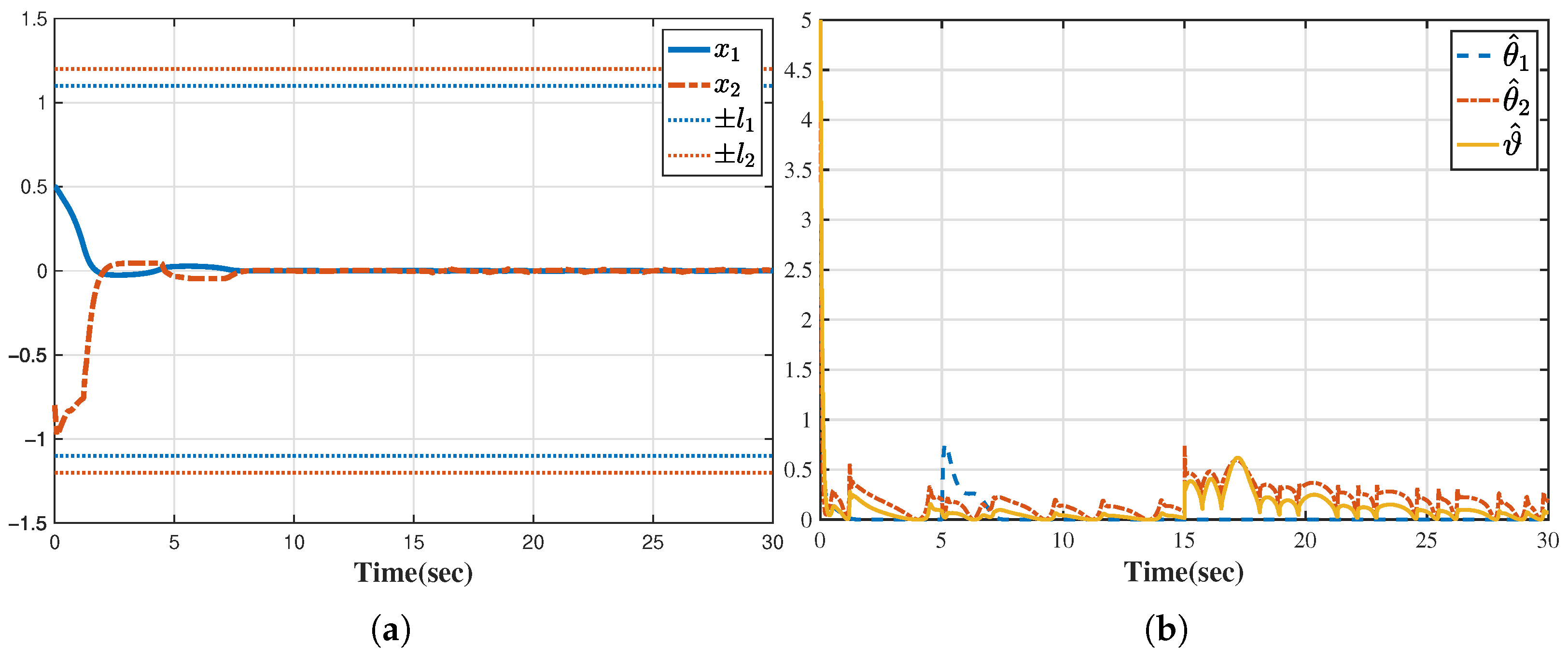
with state constraints l 1 < x 1 < l 1 , l 2 < x 2 < l 2 , where l 1 = 1.1 , l 2 = 1.2 . The actuator saturation is defined as sat ( u ) = sign ( u ) · min | u | , l 0 with l 0 = 2.4 .
The sensor attack is defined as ω s ( t ) = 20 + 7 sin ( t ) cos ( 2 t ) , which is activated at t = 5 s , while the actuator attacks are specified as g u ( t ) = 1 + 0.8 cos ( 2 t ) sin ( 3 t ) , ω a ( t ) = 5 sin ( t ) and f a ( x ¯ 2 ) = cos ( 5 x 1 x 2 ) · x 1 x 2 2 , which are triggered at t = 15 s .
The construction of the adaptive controller is summarized in the following Algorithm 1. All design parameters are chosen to be τ 0 = τ 1 = τ 2 = 1 , k 1 = k 2 = 5 , σ 0 = 15 , σ 1 = 20 , σ 2 = 25 , κ 1 = κ 2 = 0.98 , ϱ 1 = ϱ 2 = 0.02 . The initial values are set to x 1 ( 0 ) = 0.5 , x 2 ( 0 ) = 0.8 , θ ^ 1 ( 0 ) = 1 , θ ^ 2 ( 0 ) = 1 , ϑ ^ ( 0 ) = 1 .
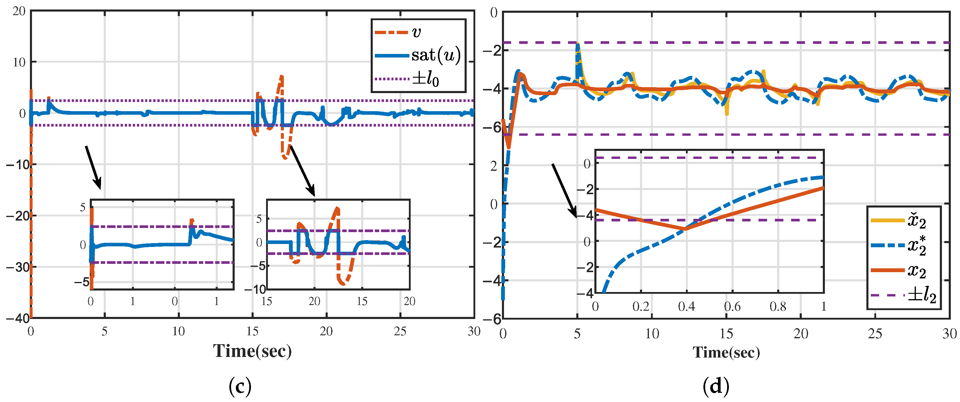
The simulation outcomes are illustrated in Figure 2. Specifically, Figure 2a shows the trajectories of states x 1 and x 2 ; Figure 2b presents the evolution of adaptive parameters; and Figure 2c illustrates the control law v together with the saturated input sat ( u ) . All system states converge to a small neighborhood around zero while strictly remaining within their prescribed constraints. The adaptive parameters respond promptly to attack events at t = 5 s and t = 15 s, demonstrating strong online adaptability. The overall response in Figure 2a–c indicates that even under actuator saturation and input deception, the system maintains only small fluctuations, verifying the robustness of the proposed method.
Algorithm 1 Adaptive Controller Implementation
1:
Inputs: Corrupted state measurements x ˇ i , constraint bounds l i , design parameters k i , σ i , σ 0 , κ i , m i , i , τ i , τ 0 ( i = 1 , 2 ).
2:
Initialization: Compute D 1 = κ 1 l 1 , D 2 = κ 2 l 2 m 2 , choose θ ^ 1 ( 0 ) , θ ^ 2 ( 0 ) and ϑ ^ ( 0 ) .
3:
Set z 1 = x ˇ 1 and z 2 = x ˇ 2 M 2 ( x 2 * ) .
4:
for each time step t do
5:
   Step 1: Compute ξ 1 , Ω 1 as in (13); construct P 1 and Φ 1 = P 1 1 as in (19).
6:
   Update virtual control x 2 * and parameter θ ^ 1 using (21) and (22):
x 2 * = 1 Ω 1 θ ^ 1 Φ 1 Ω 1 tanh Ω 1 ξ 1 Φ 1 τ 1 + k 1 ξ 1 , θ ^ ˙ 1 = σ 1 θ ^ 1 + Ω 1 ξ 1 Φ 1 tanh Ω 1 ξ 1 Φ 1 τ 1 .
7:
   Step 2: Update z 2 = x ˇ 2 M 2 ( x 2 * ) ; compute ξ 2 , Ω 2 as in (13); construct Φ 2 as in (37).
8:
   Compute intermediate control α and update θ ^ 2 using (39) and (40):
α = 1 Ω 2 θ ^ 2 Φ 2 Ω 2 tanh Ω 2 ξ 2 Φ 2 τ 2 + k 2 ξ 2 , θ ^ ˙ 2 = σ 2 θ ^ 2 + Ω 2 ξ 2 Φ 2 tanh Ω 2 ξ 2 Φ 2 τ 2 .
9:
   Compute control law v and update ϑ ^ as in (42) and (43):
v = α ϑ ^ tanh Ω 2 ξ 2 ϑ ^ α τ 0 , ϑ ^ ˙ = σ 0 ϑ ^ + Ω 2 ξ 2 α .
10:
   Send command v to the plant.
11:
end for
12:
Outputs: control input v, parameter estimates θ ^ i and ϑ ^ .
To further highlight the necessity of the proposed design, Figure 2d depicts the result without the proposed coordinate transformations (i.e., using virtual control directly as in many existing methods). In this case, the ideal virtual control x 2 * temporarily exceeds the feasible range of x ˇ 2 , leading to constraint violation of x 2 between 0.2 s and 0.5 s. This comparison confirms that the proposed coordinate transformation are essential to maintain BLF feasibility and closed-loop stability.
Example 2.
To further verify the practicality and robustness of the proposed method, a comparative simulation was conducted on the following inverted pendulum system [35]:
x ˙ 1 = x 2 , x ˙ 2 = g sin x 1 m L x 2 2 cos x 1 sin x 1 m c + m L 4 3 m cos 2 x 1 m c + m + cos x 1 m c + m sat ( u ) L 4 3 m cos 2 x 1 m c + m ,
where x 1 and x 2 are the angle and angular velocity of the pendulum, respectively; sat ( u ) is the pull force of the motor. m c = 1 kg is the cart’s mass, m = 0.1  kg is the pendulum’s mass and g = 9.81 m/s2; L = 1 m is half the length of the pendulum. The state constraints are set as l 1 < x 1 < l 1 , l 2 < x 2 < l 2 , where l 1 = 1 , l 2 = 1.2 . The actuator saturation is defined as sat ( u ) = sign ( u ) · min | u | , l 0 with l 0 = 10.4 .
The deception attacks on system (52) are generated by a unified dual-sinusoidal nested modulation function:
Π i ( t ) = A i sin C i t + sin ( C i D i t ) + B i , i = 1 , 2 , ,
where A i = 1 2 ( Π i , 1 Π i , 2 ) , B i = 1 2 ( Π i , 1 + Π i , 2 ) , C i > 0 tunes the oscillation frequency, D i > 0 regulates the frequency ratio, and Π i , 1 , Π i , 2 define the bounds such that Π i , 1 Π i ( t ) Π i , 2 . The specific assignments of Π i to each attack channel are given as follows: ω s ( t ) = Π 1 ( t ) , g u ( t ) = 1 + Π 2 ( t ) , ω a ( t ) = Π 3 ( t ) , and f a ( χ 1 , χ 2 ) = cos ( χ 1 χ 2 ) + χ 1 χ 2 2 . The attack parameters values ( Π i , 1 , Π i , 2 , C i , D i ) are chosen as: Π 1 , 1 = 0.3 , Π 1 , 2 = 0.5 , C 1 = 4 , D 1 = 5 , Π 3 , 1 = 0.5 , Π 3 , 2 = 1 , C 3 = 2.5 , D 3 = 2 , Π 4 , 1 = 2 , Π 4 , 2 = 2 , C 4 = 3 , D 4 = 5 . The initial values are set as χ 1 ( 0 ) = 0.5 , χ 2 ( 0 ) = 0.8 , Θ ^ 1 ( 0 ) = Θ ^ 2 ( 0 ) = Λ ^ 2 ( 0 ) = 1 . All attacks activates at 0 s and last to the end of simulation.
All design parameters are chosen to be τ 0 = τ 1 = τ 2 = 0.1 , k 1 = k 2 = 1 , σ 0 = 0.1 , σ 1 = 0.1 , σ 2 = 0.1 , κ 1 = 0.69 , κ 2 = 0.49 , ϱ 1 = ϱ 2 = 0.02 . The initial values are set to x 1 ( 0 ) = 0.5 , x 2 ( 0 ) = 0.8 , θ ^ 1 ( 0 ) = θ ^ 2 ( 0 ) = ϑ ^ ( 0 ) = 1 .
Figure 3 and Figure 4 compare the proposed controller with a baseline adaptive controller [25], which removes feasibility conditions but does not consider actuator saturation or deception attacks. In Figure 3 (standard setting with both saturation and deception), the proposed controller keeps x 1 and x 2 within their constraints, whereas the baseline controller fails to guarantee constraint satisfaction for x 2 , which frequently exceeds ± l 2 during the run. Figure 3c shows the actual actuator input sat ( u ) (after attack and saturation): the baseline command spends long intervals at the saturation limits, reflecting severe interaction between attack-induced distortion and the saturation nonlinearity, while the proposed scheme reduces the time in saturation and yields smoother actuation.
For a fair comparison with the baseline design, Figure 4 reports the case without actuator saturation. Even under this relaxed condition, the baseline still shows a temporary violation of the x 2 constraint in the initial 0–0.2 s interval and produces extremely large control effort: its unconstrained command v approaches 800 N (Figure 3c). In contrast, the proposed controller maintains small control effort with peak 20 N and exhibits faster settling with smaller oscillations (Figure 4a–c).
Summary. The results demonstrate that the proposed method (i) enforces state constraints under the compounded deception + saturation condition, (ii) mitigates saturation-attack interaction (fewer/lighter saturation episodes), and (iii) achieves lower control effort than the baseline, underscoring both robustness and practical implementability.
Remark 4.
The controller parameters can be tuned following these principles: (i) The feedback gains k i primarily affect convergence speed—larger values accelerate response but may induce overshoot or stronger saturation effects. (ii) The adaptive gains σ i determine the adaptation rate—excessively large values may cause oscillations, while overly small values slow parameter learning. (iii) The constants τ i balance transient speed and smoothness of the tanh ( · ) function—smaller τ i yield tighter approximation but sharper nonlinearity. (iv) The constraint coefficients κ i and ϱ i define the tightness of the barrier function and should be chosen such that the initial states lie strictly within the admissible bounds. These guidelines facilitate reproducibility and adaptation to various application scenarios. Moreover, the adaptive structure maintains robustness against moderate parameter deviations, as θ ^ i and ϑ ^ are continuously updated to compensate for model and attack-induced uncertainties. The proposed recursive design can also be extended to non-interacting MIMO systems, whereas for systems with strong couplings, additional observer-based decoupling mechanisms would be required, which is left for future work.

5. Conclusions

This paper proposes a novel adaptive control strategy for constrained nonlinear systems subject to dual-channel deception attacks and actuator saturation. To ensure state constraint satisfaction under sensor attacks, a modified coordinate transformation is introduced to preserve the feasibility of the BLF framework. On this basis, an improved BLF-based controller is developed to maintain all system states within prescribed bounds, even under corrupted measurements. Furthermore, the combined effects of actuator saturation and actuator-side deception are analytically addressed within a unified framework. An adaptive decoupling-compensation mechanism is designed to mitigate these adverse influences. Future work will focus on (1) extending the scheme toward fixed-time or predefined-time stabilization for improved transient performance; (2) integrating dynamic surface control (DSC) to reduce computational complexity; and (3) developing adaptive event-triggered mechanisms to minimize communication load and attack exposure. In addition, hardware-in-the-loop and embedded real-time implementations will be pursued to experimentally validate the controller under realistic communication delays and computational constraints.

Author Contributions

Conceptualization, S.Z.; methodology, S.Z.; software, S.Z.; validation, M.L.; investigation, S.Z.; resources, P.Z.; writing—original draft preparation, S.Z.; writing—review and editing, P.Z. and M.L.; supervision, P.Z. All authors have read and agreed to the published version of the manuscript.

Funding

This research received no external funding.

Data Availability Statement

The original contributions presented in this study are included in the article. Further inquiries can be directed to the corresponding author.

Conflicts of Interest

The authors declare no conflicts of interest. The funders had no role in the design of the study; in the collection, analyses, or interpretation of data; in the writing of the manuscript; or in the decision to publish the results.

Appendix A. Useful Lemmas

Lemma A1
([36]). (Young’s inequality) For any ϕ , ψ R and ε > 0 , it holds that
ϕ ψ ε α α | ϕ | α + 1 β ε β | ψ | β ,
where α > 1 , β > 1 and 1 α + 1 β = 1 .
Lemma A2
([37]). For any real-valued continuous function f ( ϕ , ψ ) , there exist smooth scalar functions a ( ϕ ) > 1 and b ( ψ ) > 1 such that | f ( ϕ , ψ ) | a ( ϕ ) b ( ψ ) .
Lemma A3
([38]). For any ϕ R and constant τ > 0 , the following inequalities hold:
0 | ϕ | ϕ tanh ϕ τ ς τ , 0 | ϕ | ϕ 2 ϕ 2 + τ 2 < τ ,
where ς = 0.2785 is a constant.
Lemma A4.
Consider the differential equation f ˙ ( t ) = α f ( t ) + g ( t ) , where α > 0 , g ( t ) 0 . If the initial value satisfies f ( t 0 ) 0 , then f ( t ) 0 for all t t 0 .
Proof. 
Let h ( t ) = f ( t 0 ) e α ( t t 0 ) , which satisfies h ˙ ( t ) = α h ( t ) and h ( t 0 ) = f ( t 0 ) 0 . Since α > 0 , g ( t ) 0 and f ˙ ( t ) α f ( t ) , by the comparison principle we obtain f ( t ) h ( t ) 0 for all t t 0 . □

References

  1. Zhao, D.; Wang, Z.; Wei, G.; Han, Q.-L. A dynamic event-triggered approach to observer-based PID security control subject to deception attacks. Automatica 2020, 120, 109128. [Google Scholar] [CrossRef]
  2. Hu, L.; Wang, Z.; Han, Q.L.; Liu, X. State estimation under false data injection attacks: Security analysis and system protection. Automatica 2018, 87, 176–183. [Google Scholar] [CrossRef]
  3. Yang, Y.; Huang, J.; Su, X.; Deng, B. Adaptive control of cyber-physical systems under deception and injection attacks. J. Frankl. Inst. 2021, 358, 6174–6194. [Google Scholar] [CrossRef]
  4. Wang, X.; Zhao, P. An adaptive control scheme against state-dependent sensor attacks and input-dependent actuator attacks in cyber-physical systems. IET Control Theory Appl. 2023, 17, 1061–1072. [Google Scholar] [CrossRef]
  5. Ren, X.; Yang, G. Adaptive control for nonlinear cyber-physical systems under false data injection attacks through sensor networks. Int. J. Robust Nonlinear Control 2019, 30, 65–79. [Google Scholar] [CrossRef]
  6. Yang, Y.; Huang, J.; Su, X.; Wang, K.; Li, G. Adaptive control of second-order nonlinear systems with injection and deception attacks. IEEE Trans. Syst. Man Cybern. Syst. 2022, 52, 574–581. [Google Scholar] [CrossRef]
  7. Yoo, S. Neural-network-based adaptive resilient dynamic surface control against unknown deception attacks of uncertain nonlinear time-delay cyber-physical systems. IEEE Trans. Neural Netw. Learn. Syst. 2020, 31, 4341–4353. [Google Scholar] [CrossRef]
  8. Wang, X.; Zhou, Y.; Yang, L. Event-triggered cooperative adaptive neural control for cyber-physical systems with unknown state time delays and deception attacks. IEEE Trans. Syst. Man Cybern. Syst. 2023, 53, 3540–3552. [Google Scholar] [CrossRef]
  9. Wang, H.; Wang, Y.; Zhuang, G.; Xia, J. Dynamic event-based prescribed-time practical consensus for nonlinear multi-agent systems under DoS and deception attacks. Nonlinear Dyn. 2025, 116, 16629–16642. [Google Scholar] [CrossRef]
  10. Ju, Z.; Zhang, H.; Tan, Y. Deception attack detection and estimation for a local vehicle in vehicle platooning based on a modified UFIR estimator. IEEE Internet Things J. 2020, 7, 3693–3705. [Google Scholar] [CrossRef]
  11. Wang, H.; Ren, Y.; Fang, Y. An optimal attack strategy based on adversary-modified historical innovations. IEEE Internet Things J. 2024, 11, 33337–33345. [Google Scholar] [CrossRef]
  12. Wittenmark, B. Adaptive dual control methods: An overview. IFAC Proc. Vol. 1995, 28, 67–81. [Google Scholar] [CrossRef]
  13. Lei, W.; Li, C.; Chen, M.Z.Q. Robust adaptive tracking control for quadrotors by combining PI and self-tuning regulator. IEEE Trans. Control Syst. Technol. 2019, 27, 2663–2671. [Google Scholar] [CrossRef]
  14. Lovi, A.; Fidan, B.; Nielsen, C. Multiple model reference adaptive control with blending for nonsquare multivariable systems. IEEE Trans. Autom. Control 2025, 70, 5780–5791. [Google Scholar] [CrossRef]
  15. Chu, H.; Yi, B.; Zhang, G.; Zhang, W. Performance improvement of consensus tracking for linear multiagent systems with input saturation: A gain scheduled approach. IEEE Trans. Syst. Man Cybern. Syst. 2020, 50, 734–746. [Google Scholar] [CrossRef]
  16. Cao, N.; Lynch, A.F. Inner-outer loop control for quadrotor UAVs with input and state constraints. IEEE Trans. Control Syst. Technol. 2016, 24, 1797–1804. [Google Scholar] [CrossRef]
  17. Tee, K.; Ge, S.; Tay, E. Barrier Lyapunov functions for the control of output-constrained nonlinear systems. Automatica 2009, 45, 918–927. [Google Scholar] [CrossRef]
  18. He, W.; Chen, Y.; Yin, Z. Adaptive neural Network control of an uncertain robot with full-state constraints. IEEE Trans. Cybern. 2016, 46, 620–629. [Google Scholar] [CrossRef]
  19. Song, Y.; Zhou, S. Tracking control of uncertain nonlinear systems with deferred asymmetric time-varying full state constraints. Automatica 2018, 98, 314–322. [Google Scholar] [CrossRef]
  20. Yuan, X.; Yang, B.; Pan, X.; Zhao, X. Fuzzy control of nonlinear strict-feedback systems with full-state constraints: A new barrier function approach. IEEE Trans. Fuzzy Syst. 2022, 30, 5419–5430. [Google Scholar] [CrossRef]
  21. Yuan, X.; Chen, B.; Lin, C. Neural adaptive fixed-time control for nonlinear systems with full-state constraints. IEEE Trans. Cybern. 2023, 53, 3048–3059. [Google Scholar] [CrossRef]
  22. Cuan, Z.; Ding, D.; Liu, X.; Wang, Y. Adaptive fuzzy control for state-constrained nonlinear cyber-physical systems with unmodeled dynamics against malicious attacks. IEEE Trans. Ind. Cyber-Phys. Syst. 2023, 1, 56–65. [Google Scholar] [CrossRef]
  23. Liu, Z.; Tang, J.; Zhao, Z.; Zhang, S. Adaptive neural network control for nonlinear cyber-physical systems subject to false data injection attacks with prescribed performance. Philos. Trans. R. Soc. A Math. Phys. Eng. Sci. 2021, 379, 20200372. [Google Scholar] [CrossRef]
  24. Dong, S.; Li, Y. Adaptive fuzzy event-triggered formation control for nonholonomic multirobot systems with infinite actuator faults and range constraints. IEEE Internet Things J. 2024, 11, 1361–1373. [Google Scholar] [CrossRef]
  25. Zhao, K.; Song, Y. Removing the feasibility conditions imposed on tracking control designs for state-constrained strict-feedback systems. IEEE Trans. Autom. Control 2019, 64, 1265–1272. [Google Scholar] [CrossRef]
  26. Chen, M.; Ge, S.; Ren, B. Adaptive tracking control of uncertain MIMO nonlinear systems with input constraints. Automatica 2011, 47, 452–465. [Google Scholar] [CrossRef]
  27. Wen, C.; Zhou, J.; Liu, Z.; Su, H. Robust adaptive control of uncertain nonlinear systems in the presence of input saturation and external disturbance. IEEE Trans. Autom. Control 2011, 56, 1672–1678. [Google Scholar] [CrossRef]
  28. Fan, Y.; Yang, C.; Li, Y. Fixed-time neuro-optimal adaptive control with input saturation for uncertain robots. IEEE Internet Things J. 2024, 11, 28906–28917. [Google Scholar] [CrossRef]
  29. Ma, J.; Ge, S.; Zheng, Z.; Hu, D. Adaptive NN control of a class of nonlinear systems With asymmetric saturation actuators. IEEE Trans. Neural Netw. Learn. Syst. 2015, 26, 1532–1538. [Google Scholar] [CrossRef] [PubMed]
  30. Li, Y.; Tong, S.; Li, T. Composite adaptive fuzzy output feedback control design for uncertain nonlinear strict-feedback systems with input saturation. IEEE Trans. Cybern. 2015, 45, 2299–2308. [Google Scholar] [CrossRef]
  31. Zhou, Q.; Wang, L.; Wu, C.; Li, H.; Du, H. Adaptive fuzzy control for nonstrict-feedback systems with input saturation and output constraint. IEEE Trans. Syst. Man Cybern. Syst. 2017, 47, 1–12. [Google Scholar] [CrossRef]
  32. Wu, Y.; Xie, X. Robust adaptive control for state-constrained Nonlinear Systems with Input Saturation and Unknown Control Direction. IEEE Trans. Syst. Man Cybern. Syst. 2021, 51, 1192–1202. [Google Scholar] [CrossRef]
  33. Zhao, N.; Tian, Y.; Zhang, H.; Herrera Viedma, E. Learning-based adaptive fuzzy output feedback control for MIMO nonlinear systems with deception attacks and input saturation. IEEE Trans. Fuzzy Syst. 2024, 32, 2850–2862. [Google Scholar] [CrossRef]
  34. Gao, Y.; Niu, B.; Chen, W.; Wang, H.; Mu, C.; Wen, G. Adaptive control of constrained nonlinear CPSs under deception attacks through sensor and actuator networks. IEEE Trans. Circuits Syst. II Express Briefs 2024, 71, 1241–1245. [Google Scholar] [CrossRef]
  35. Wei, W.; Zhang, W. Command-filter-based adaptive fuzzy finite-time output feedback control for state-constrained nonlinear systems with input saturation. IEEE Trans. Fuzzy Syst. 2022, 30, 4044–4056. [Google Scholar] [CrossRef]
  36. Deng, H.; Krstic, M. Output-feedback stochastic nonlinear stabilization. IEEE Trans. Autom. Control 1999, 44, 328–333. [Google Scholar] [CrossRef]
  37. Lin, W.; Qian, C. Adaptive control of nonlinearly parameterized systems. In Proceedings of the 40th IEEE Conference on Decision and Control (Cat. No. 01CH37228), Orlando, FL, USA, 4–7 December 2001; Volume 5, pp. 4192–4197. [Google Scholar] [CrossRef]
  38. Sun, Z.; Zhou, C.; Liu, Z.; Meng, Q. Fast finite-time adaptive event-triggered tracking for uncertain nonlinear systems. Int. J. Robust Nonlinear Control 2020, 30, 7806–7821. [Google Scholar] [CrossRef]
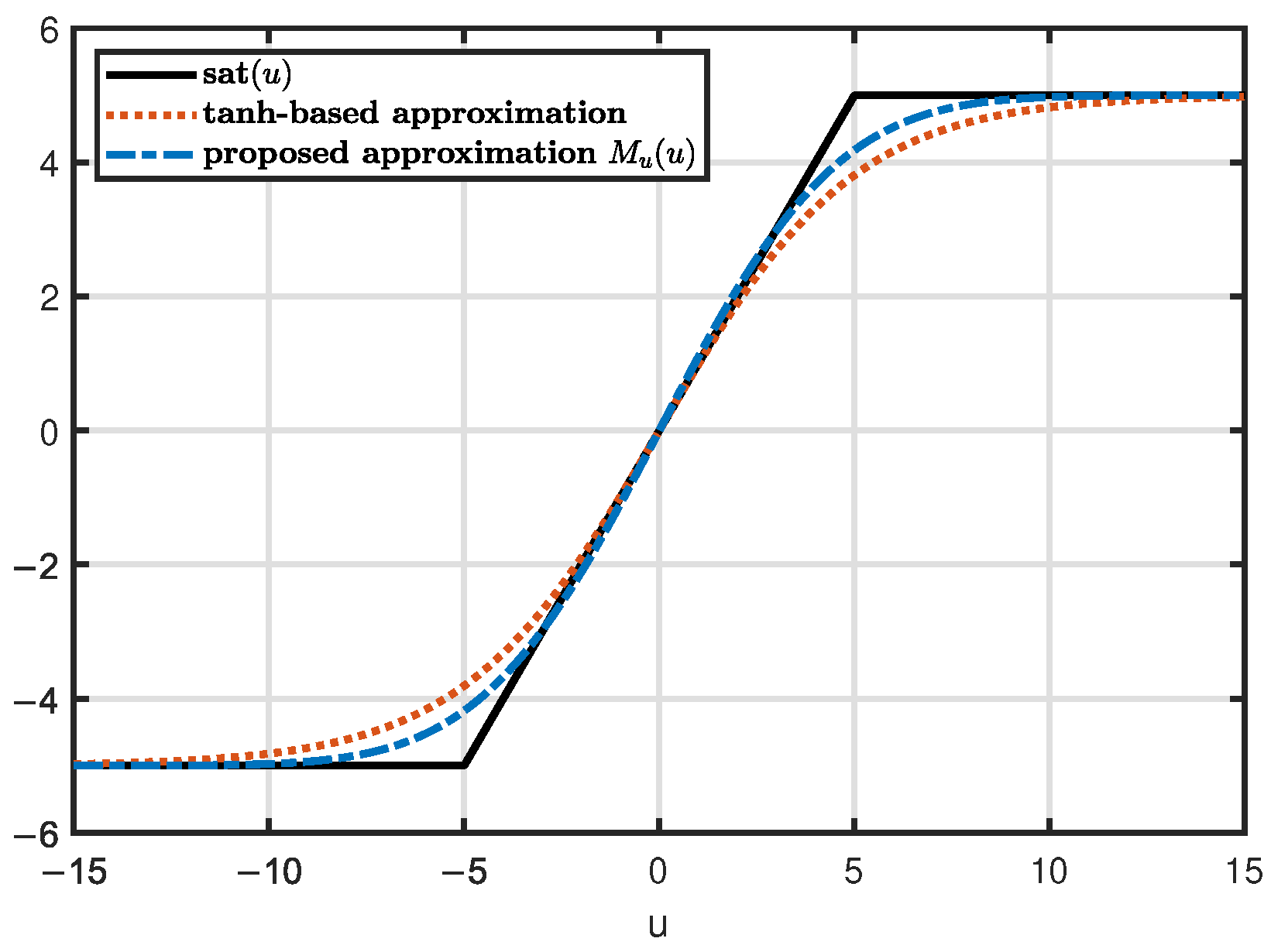
Figure 1. Trajectories of sat ( u ) with l 0 = 5 , tanh-based approximation in [27] and proposed approximation M u ( u ) with δ 0 = 0.9 .
Mathematics 13 03508 g001
Figure 2. (a) Trajectories of states x 1 , x 2 . (b) Trajectories of adaptive laws. (c) Description of the control law v and the saturated input sat ( u ) . (d) Description of the comparison: x 2 , x ˇ 2 and x 2 * .
Mathematics 13 03508 g002aMathematics 13 03508 g002b
Figure 3. Comparative results under actuator saturation and deception attacks. (a) Trajectory of the pendulum angle x 1 (rad) and its constraint ± l 1 . (b) Trajectory of the angular velocity x 2 (rad/s) and its constraint ± l 2 . (c) Actual actuator input sat ( u ) (N) after attack and saturation (proposed vs. baseline).
Mathematics 13 03508 g003
Figure 4. Comparative results without actuator saturation constraint. (a) x 1 (rad) responses of the proposed and baseline controllers. (b) x 2 (rad/s) responses of the proposed and baseline controllers. (c) Unconstrained control command v (N) of the baseline controller and the proposed controller.
Mathematics 13 03508 g004
Disclaimer/Publisher’s Note: The statements, opinions and data contained in all publications are solely those of the individual author(s) and contributor(s) and not of MDPI and/or the editor(s). MDPI and/or the editor(s) disclaim responsibility for any injury to people or property resulting from any ideas, methods, instructions or products referred to in the content.